

Page 1
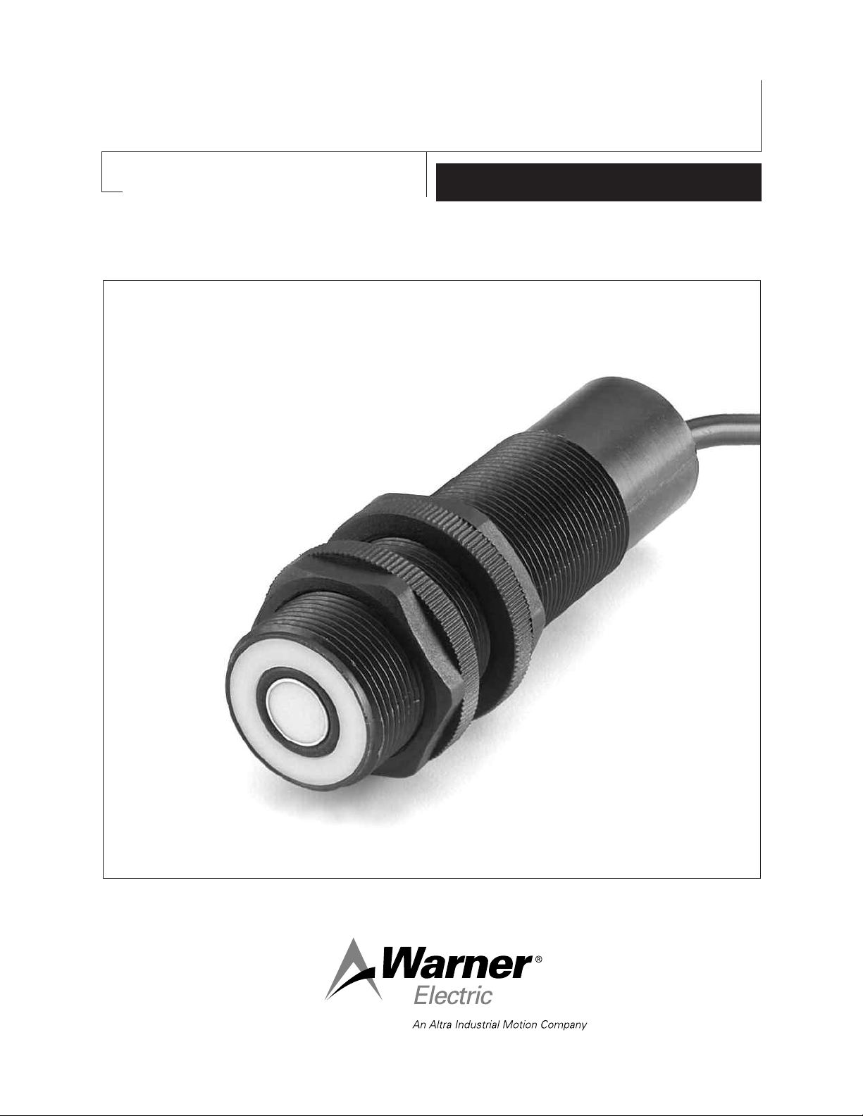
Ultrasonic Sensors
with Analog Output
P-1256
819-0455
Model : UT30UP- DCA4- 1016- CSI
Par t Number : 7600- 448- 001
Model : UT30UP- DCA4- 2032- CSI
Par t Number : 7600- 448- 002
Technical Data Sheet
Page 2
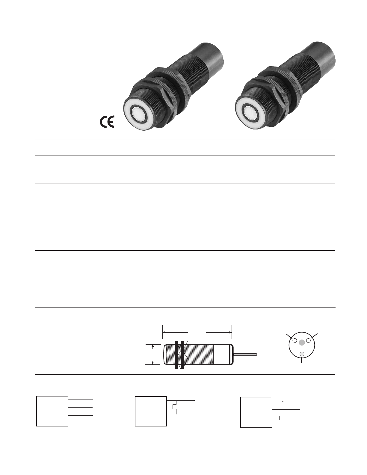
Ultrasonic Sensors
104 mm
4.1"
1.18"
30mm
with Analog Output
4-20mA and 0-10V
Wire selectable inverted
or non-inverted outputs
Threaded
plastic barrel
M 30 x 1.5
Sensing range 101..1016 mm 203..2032 mm
(4-40") (8-80")
Switching functions/output Analog 4-20mA and 0-10V Analog 4-20mA and 0-10V
Ordering Model description UT30UP-DCA4-1016-CSI UT30UP-DCA4-2032-CSI
Information Part number 7600-448-001 7600-448-002
Threaded
plastic barrel
M 30 x 1.5
Electrical data
Voltage range min./max. 20-30V DC reverse polarity protected 20-30V DC reverse polarity protected
Input current 50mA 50mA
Transducer frequency 212 KHz 150 KHz
Short circuit protected Yes Yes
LED - (strength indicator) Yes - green to red; see (Note D) Yes - green to red; see (Note D)
Response time 30 mSec 50 mSec
Range control Zero and span (2 potentiometers) Zero and span (2 potentiometers)
Mechanical Data
Temperature range min./max 0°C/+60°C / 32°F/140°F 0°C/+60°C / 32°F/140°F
Degree of protection IP 65/NEMA 12 IP 65/NEMA 12
Body material Valox plastic Valox plastic
Termination cable 2 m/6 ft. PVC 4 x 22 gauge PVC 4 x 22 gauge
Plug/socket Versions available to order Versions available to order
Accessories 1) Brackets 1) Brackets
Humidity 0-95% non-condensing 0-95% non-condensing
1) Brackets for M 30 x 1.5
Ordering Information
Ordering Information
Plastic - BK5-D34PA
Part number 596-0223-041
Dimensions
Adjustment Pots
Zero and Span Control
P1
P2
Metal - M 30 ST
Part number 7430-448-003
Wiring Data
Brown +
Blue –
White
Black
Non Inverted Output
20-30V DC
Voltage 0-10V
Current 4-20mA
Brown +
Blue –
White
Black
20-30V DC
Current 20-4mA
Current Output Inverted
LED
Brown +
Blue –
White
Black
20-30V DC
Voltage 10-0V
Voltage Output Inverted
Page 3

–8°
4" to 40"
+8°
–10°
8" to 80"
+10°
Allowable Angle of Tilt
10V
20mA
0V
4mA
40"
80"
4"8"40" Range
80" Range
Adjustable
Maximum Analog Ranging
Target
Op er a tion and Set-Up
0V
4mA
10V
20mA
40"
80"
4"8"40" Range
80" Range
Adjustable
Inverted Analog Ranging
Target
10V
20mA
0V
4mA
15"
24"
10"
12"
40" Range
80" Range
Adjustable
Minimum Analog Ranging
Target
Beam Spread vs. Target Distance
1.5Beam Diameter (in.) 2.0 3.5 4.5 5.0 6.5 8.0 8.5 9.0 9.0
40
Distance from Sensor (in.)
6 81012 16 20 24 2830
4.5Beam Diameter (in.) 8.0
10.0
13.0 14.0 14.5 14.5
100
Distance from Sensor (in.)
20
30
40 50 60 72
Minimum Analog Ranging
Minimum analog ranging is when you desire to
have the full 4-20mA or 0-10V output over the
minimum 5 inch sensing span. 5 inches of
min i mum sensing span can be adjusted any where
in the sensing range. For example 10"-15" or
25"-30". To make this ad just ment, you place your
target at the minimum sensing range and adjust
P1 to 4mA. Then move your target to the
max i mum sensing range and adjust P2 to 20mA.
Re-check the readings and make appropriate
ad just ments, if necessary. See diagram (A).
Maximum Analog Ranging
Analog sensing in the maximum range means
uti liz ing the entire 36" span (4"-40") and 72" span
(8"-80"). To adjust, set your target at the min i mum
range, either 4" or 8" and adjust P1 to 4mA. Move
the target to the maximum range and adjust P2 to
20mA. Re-check read ings and make ap pro pri ate
ad just ments, if necessary. See di a gram (B).
Inverted Analog Outputs
Inverted outputs means that the 4-20mA or 0-10V
output signal will decrease proportionally with
dis tance. To adjust, place your target at the
min i mum sensing distance and ad just P1 to 20mA.
Place your target at the max i mum sensing dis tance
and adjust P2 to 4mA. Re-check read ings and
make ap pro pri ate ad just ments, if nec es sary. See
diagram (C).
LED Operation ( Not e D)
The LED is green when the unit is powered up.
It will fade to red as a target is detected with
in creased intensity as more sig nal is be ing
re flect ed from the target. Note: Any color other
than green equals a workable signal level.
Adjustment Pots
Zero and Span Control
P1
P2
LED
Diagram A
Diagram B
Diagram C
Page 4

Sensors, Industrial Switches and Safety Technology Products
Warner Electric has many years of experience in
applying sensors in motion control applications.
Warner Electric’s broad range of innovative and
technologically advanced product range offers our
customers the exact solution to satisfy their sensing applications.
Our full product range is available through
more than 800 distributor locations, throughout
the United States, Canada and Mexico.
Local Sales Support is provided by a well
trained sales force that is backed up by
Application Engineering providing immediate technical support.
Non-Contact Sensors
Photoelectric Sensors
Ultrasonic Sensors
Inductive Proximity Sensors
Capacitive Sensors
Magnetic Sensors
Industrial Switches
Limit Switches
Foot Switches
Cable Pull Switches
Safety Technology Products
Safety Interlocks
Cable Pull Switches
Approvals and Certification
Each model is individually identified with its own certification.
Documentation is available upon request.
Coded Magnetic Monitoring Systems
Warner Electric LLC
31 Industrial Park Road • New Hartford, CT 06057
815-389-3771
www.warnerelectric.com
P-1250 819-0455 6/12 Printed in USA
• Fax: 815-389-2582
 Loading...