

Page 1
TCS-200-1 and TCS-200-1H
Tension Controls
P-2003-2
819-0420
Service & Installation Instructions
Page 2

Contents
Introduction . . . . . . . . . . . . . . . . . . . . . . . . . . . . 2
Theory of Operation . . . . . . . . . . . . . . . . . . . . . . 3
Technical Specifications. . . . . . . . . . . . . . . . . . . 3
Installation
Control Mounting. . . . . . . . . . . . . . . . . . . . . . 4
External Sensor Mounting. . . . . . . . . . . . . . . 5
System Wiring . . . . . . . . . . . . . . . . . . . . . . . . . . 5
System Start-Up and Adjustment . . . . . . . . . . 11
Voltage Tables . . . . . . . . . . . . . . . . . . . . . . . . . 19
System Troubleshooting. . . . . . . . . . . . . . . . . . 20
Component Parts List
Coupling, MCS-605-1 284-8000-003
Roll Pin (Drive) for Sensor Coupling 679-8001-067
TCS-200-1 Tension Control 6910-448-086
TCS-200-1H Tension Control 6910-448-087
Ultrasonic Sensor 4-40in 7600-448-001
Power Source
The TCS-200-1 series Tension Controls operates
from a power source of 115 or 230 VAC, 50/60 Hz
input. Primary voltage is determined by the
customer's input voltage source. The control is
factory set to accept 115 VAC input. Refer to the
wiring section for 230 VAC input connections.
Control
The TCS-200-1 series controls are selectable
voltage or current controlled power supply
designed to power up to a 16 magnet Electro Disc
tension brake system, Electromagnetic Particle
Brakes, TB series brakes or Advanced Technology
tension brakes. This control can be operated
manually from the front panel or remotely via an
analog voltage input, a current input, a remote
pot, or a roll follower. External inputs are also
provided for remote brake "off", "run", and "stop"
functions, as well as front panel control of these
functions.
List of Illustrations and Figures
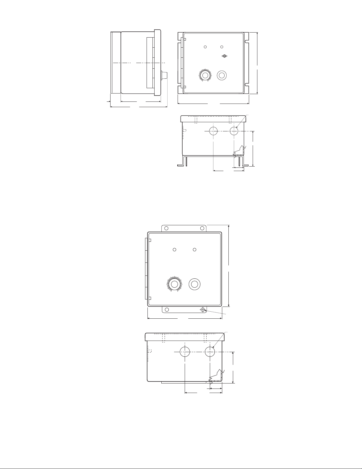
Figure 1 Dimensional Data, Mounting . . . . . . .6
Figure 2 Power Connections . . . . . . . . . . . . . .7
Figure 3 Brake Connections . . . . . . . . . . . . . . .8
Figure 4 Remote Torque and Roll
Follower Connections . . . . . . . . . . . . .9
Figure 5 Remote Switch, Analog Input and
Analog Input Isolation Connections .10
Tables 1,2,3 Voltage/Current Tables . . . . . . . . . . .19
Templates TCS-200-1H Template . . . . . . . . . . .21
TCS-200-1 Template . . . . . . . . . . . .21
Introduction
The Warner Electric Tension Control system is
comprised of a tension brake, control module, and
optional external sensor input.
This manual has been designed to cover
installation, start-up, adjustment, and
maintenance of your tension control system and
covers the control system only. Further
information on brake sizing and selection can be
found in catalogs P-1234 or P-771.
The analog voltage and current inputs are
electrically isolated from the main power circuitry
of the control when 15-35 VDC supply is provided
to maintain full isolation. If isolation is not
needed, an on board 15 VDC supply is jumpered
to act as a default.
Sensors
When the TCS-200-1 series controls are operated
in a remote torque adjust mode, a 1,000 ohm
potentiometer is required. This should be a linear
type potentiometer with a rating of .5 watts, 10
percent tolerance, and a .5 percent linearity.
For roll follower input applications, a 1,000 ohm
potentiometer with a rating of .5 watts, 10 percent
tolerance, and .5 percent linearity is required for
best performance.
Brakes
All 24 VDC tension brakes that Warner Electric
offers, to a maximum of 4.25 amps, can be used
with the TCS-200-1 tension control. For all 24
VDC tension brakes that require greater current
capability from the control (not to exceed 5.8
amps), use a TCS-200-1H. The brake converts
electrical current supplied by the control into
torque, which retards material flow, maintaining
the desired web tension.
Warner Electric • 800-825-9050 P-2003-2 • 819-0420
2
Page 3

Theory of Operation
When in operation, the control is powered by a
standard 115/230 VAC line. The control has a
transformer that converts that voltage to a level
suitable for any 24 VDC brake system. The signal is
rectified to DC and pulse width modulated (PWM) to
the desired brake current via the TENSION ADJUST
knob.
The front panel TENSION ADJUST feeds a small
voltage to a comparator, which compares this signal
to a triangular wave. This is where the PWM pulse is
generated. This pulse is then inverted and used to
drive a power circuit. The main brakes and a sense
brake are then energized by the power circuit at
regular intervals. From the sense brake, a growth and
decay signal is converted to a voltage that can be
added to the signal by setting a jumper on the inside
of the cover. This signal, when selected, is used to
maintain constant current to the brake. The signal
must not be selected when no sense brake is
connected.
The control has several options that allow for
external/remote tension adjust in addition to the
tension adjust pot on the front of the panel. Two
such options are the remote pot or a roll follower.
Another is the option for an analog input of voltage
or current from a PLC or ultrasonic sensor. A special
feature of the analog inputs is that they are optically
isolated from the rest of the control circuitry if an
external power source is used to power the isolated
circuits. The isolation is needed when using a PLC or
an external power supply for the ultrasonic sensor.
An internal power source is also available and
jumpered in as default if isolation is not necessary.
The tension adjust pot on the front of the panel
becomes a span adjust when any of the external
control options are connected.
The control also has the capability to duplicate the
front panel selector switch at a remote location.
Brake "off" mode overrides the tension adjustment
and provides for resetting the short circuit indicator.
In the "run" mode, output operation is normal and is
controlled by any of the front panel or remote tension
adjust features discussed above. The brake "stop"
mode provides for full output current to the brake.
The two indicators on the front of the panel are green
for "power on" and red to indicate a short circuit.
When a short occurs in the brake, the control
disables the power circuits to prevent damage. Turn
the switch to "off" to reset the short circuit indicator.
Because this is a basic tension control, no antiresidual circuits, zero adjust circuits, or other
complex control circuits (found in other Warner
Electric tension control systems) are included in the
TCS-200-1 series controls.
Technical Specifications
TCS200-1 and TCS200-1H
Input Power
115/230 VAC 50/60 Hz
Output TCS-200-1
Adjustable 0-24 VDC. Maximum of 4.25 amps
continuous. Can be used with any 24 VDC
tension brake with or without the need for a
sense coil.
Output TCS-200-1H
Adjustable 0-24 VDC. Maximum of 5.8 amps
continuous. Can be used with any 24 VDC
tension brake with or without the need for a
sense coil.
Ambient Temperature
-20° to 125° F (-29° to 51° C)
Fuse
2.5 Amp, 250 VAC, Slow-Blow
Protection
Internal short-circuit protection on driver output
stage
Sensor Inputs
• Remote Torque Adjust 1,000Ω
• Roll Follower 1,000Ω
• Analog voltage input, 0-10 VDC (Optically
isolated when 15-35 VDC supplied from external
source)
• Analog current input, 4-20mA (Optically
isolated when 15-35 VDC supplied from external
source)
Warner Electric • 800-825-9050 P-2003-2 • 819-0420
3
Page 4

Auxiliary Inputs
• Brake Stop – Applies full voltage to the
connected brakes. Active high input
• Brake Run – Voltage to the brake is controlled by
any of the sensor inputs and/or the front panel
tension adjust. Active high input.
o 1. If you are using a PLC or an
external power supply with this control, you must
enable the isolation of the control.
o 2. The TCS-200-1 can not operate a single brake
or brakes that require more than 4.25 amps
continuous.
• Brake Off – Removes output current to the brake.
Puts the brake at zero current level. Active high
input.
Note 1: The remote input signal for these functions
requires a minimum contact rating of 20 VDC at .01
amps and a maximum of state leakage current less
than 100 micro-amps.
Note 2: The remote switch input overrides the front
panel switch.
Front Panel
• Tension Adjust – Provides current adjust to the
brake from 0 to 100%. In the remote and
analog input mode, provides for maximum output
level set to the brake.
• Brake Mode Switch –
Modes: "stop"-brake full on
"run" -normal operation
o 3. The TCS-200-1H can not operate a single
brake or brakes that require more than 5.8 amps
continuous.
This Installation and Operation Manual has been
arranged for the systematic installation and start-up
of your tension control system. To achieve the best
possible results, we recommend checking off each
completed step in the space provided before
proceeding to the next step.
Sample
o Attach the TCS-200 control chassis to the
mounting surface and secure with mounting
hardware.
Check box after completing each step.
Control Mounting
"off" -brake off
Indicators (Front Panel)
• Green LED indicates AC power has
been applied to the control.
• Red LED indicates there is a short on the output.
Turn the front panel switch "off" to reset the short
circuit.
General
The control chassis must be considered NEMA 1
and should be kept clear of areas where foreign
material, dust, grease, or oil might affect control
operation.
Potentiometers (supplied by the customer)
• Remote Torque Adjust
1,000 ohms, 10% tolerance, .5% linearity,
.5 watts, linear taper
• Roll Follower – 1,000 ohms, 10% tolerance, .5%
linearity, .5 watts, linear taper
o 1. Determine a suitable location for the control to
be mounted. Consideration should be given to
whether the front panel adjustments will require
access by the operator.
o 2. Using the dimensional data supplied in Figure
1a and Figure 1b, drill four mounting holes using
a #16 drill if #8 through-bolts are used. For #8
capscrew mounting, use a #29 drill and tap holes
for #8 screws. Templates for hole drilling are
found on page 21.
o 3. Attach the TCS-200-1 or TCS-200-1H control
chassis to the mounting surface and secure with
mounting hardware.
Note: The control chassis has been designed to
accommodate two half-inch conduits for wiring when
the control is mounted to the machine frame.
Warner Electric • 800-825-9050 P-2003-2 • 819-0420
4
Page 5

o 4. Attach conduit or seal tight connectors.
The control is now ready to be wired. Refer to the
wiring section of this manual for proper system
wiring.
Note: If angular rotation is not adequate, insufficient
output from the control is possible. In this case, a
timing belt drive between the roll follower pivot-point
and the sensor potentiometer may be necessary to
obtain adequate angular rotation.
Brake Installation
Refer to the brake manual that is appropriate for the
brake selected for its installation procedures.
External Sensor Mounting (Optional)
Options for four types of external sensor inputs are
available. These consist of either an external torque
adjust, roll follower input that provides a signal
directly proportional to the diameter of the roll to be
processed, analog voltage, or analog current input.
Determine which type of external sensor will be used
and proceed to the appropriate section of this
manual.
Remote Torque Adjust Potentiometer (Optional)
o 1. Select an appropriate mounting location for
the external torque-adjust potentiometer.
Note: In determining this mounting location, take into
consideration the routing of the wires necessary to
connect the control, access for the operator, and
space required by the physical size of the
potentiometer.
o 2. Drill a mounting hole based on the bushing
diameter of the potentiometer selected.
o 3. Mount and secure the potentiometer.
o 2. Secure the roll follower potentiometer. This
completes the mounting for a roll follower
potentiometer. Refer to the wiring section of this
manual for proper control wiring.
Analog Input (Optional)
o 1. Select an appropriate mounting location for
the PLC or ultrasonic sensor.
o 2. Mount and secure the PLC or ultrasonic
sensor according to the specifications for those
products.
This completes the mounting. Refer to the wiring
section of this manual for proper control wiring.
System Wiring
System Wiring Precautions
The following wiring precautions will help you
properly wire and install a trouble free system.
o 1. Use a proper gauge wire for all wiring.
o 2. Insure that wires are cut and stripped so that
no excess bare wire is exposed.
o 3. Segregate AC input power from control
switching and external sensor wiring (if used).
This completes the mounting for an external remote
torque adjust potentiometer. Refer to the wiring
section of this manual for proper control wiring.
o 4. Do not run AC power lines with DC power,
input sensor wiring, or switching wiring. Noise
transients can be easily transferred, causing
erratic control operation.
Roll Follower Adjust Potentiometer (Optional)
o 5. Use shielded cable when possible for
o 1. Mount the roll follower potentiometer and
determine the amount of angular rotation at the
potentiometer shaft.
connecting the TCS-200-1 to external switches,
the sensor potentiometer, PLC's, and ultrasonic
sensor.
o 6. Under no circumstances should auxiliary
accessories be operated from the TCS-200-1
control.
Warner Electric • 800-825-9050 P-2003-2 • 819-0420
5
Page 6
WA RNER ELECTRIC
®
TCS-200-1H
POWER SHORT
TENSION
ADJUSTMENT
BRAKE MODE
.875 DIA. 2 PLCS.
FOR 1/2 CONDUIT
3.75
1.25
3.00
C
L
4.00
1.00
6.82
6.00
5.75
.875 DIA. 2 PLCS.
2.87
1.25
3.00
6.00
7.50
WA RNER ELECTRIC
®
TCS-200-1
POWER SHORT
TENSION
ADJUSTMENT
BRAKE MODE
.31 Dia.
TCS-200-1H with Heat Sink
Figure 1a
CS-200-1
Figure 1b
Warner Electric • 800-825-9050 P-2003-2 • 819-0420
6
Page 7

NEUTRAL
1
2
3
4
5
6
7
8
9
115 VAC
HOT
TB2
NEUTRAL
1
2
3
4
5
6
7
8
9
230 VAC
HOT
TB2
FACTORY
INSTALLED
JUMPERS
INSTALL
JUMPER
GND GND
o 7. Do not attempt to incorporate
external switching schemes between two or
more brakes and the TCS-200-1 output. This will
damage the control and void the warranty.
o 8. Do not attempt to wire two or more controls in
parallel.
TCS-200-1 Series Controls Wiring
Refer to Figure 2 for actual wiring connections.
o 1. Unlatch the front cover of the TCS-200-1.
Power
Determine if 115 VAC or 230 VAC will be used to
power the control and proceed to that section of this
manual.
Insure power is off and disconnects
open on the control panel before connecting the AC
input. Failure to do so can result in damage to
equipment and injury or even death to personnel.
o 2. Connect one of the jumpers to terminals 5
and 6 of terminal block TB2 and discard the
spare jumper.
o 3. Connect the 230 VAC power to terminals 4 & 8
of terminal block TB2. Secure the terminal
screws.
o 4. Connect an earth ground wire between
terminal 9 of terminal block TB2 and an
unpainted metal surface of the control panel to
ensure a good ground connection. Secure the
terminal screw. Make sure the panel itself is
properly grounded.
115 VAC
Refer to Figure 2a for 115 VAC power input
connections.
o 1. Connect the 115 VAC power to terminals 4 & 8
of terminal block TB2 located in the base of the
TCS-200-1 enclosure. Secure the terminal
Note: Do not apply power to the system at this
point.
Brake
Determine the type of brake to be used with this
control and proceed to that section of this manual.
Figure 2
screws.
Insure connections are tightly secured. Intermittent
a. 115 AC Power Wiring b: 230 VAC Power Wiring
o 2. Connect an earth ground wire between
terminal 9 of terminal block TB2 and an
unpainted metal surface of the control panel to
shut down and output current to the brake will be
removed.
connection will cause the control to
ensure a good ground connection. Secure the
terminal screw. Make sure the control panel itself
is properly grounded.
230 VAC Input
Refer to Figure 2b for 230 VAC power input
Electro Disc Tension Brake
Refer to Figure 3a for the Electro Disc Tension Brake
wiring connections.
connection.
o 1. Connect the red wire from one brake magnet
o 1. Remove the factory installed jumpers from
Warner Electric • 800-825-9050 P-2003-2 • 819-0420
terminals 4 & 5 and 6 & 7 of terminal block TB2
located in the base of the TCS-200-1 enclosure.
to terminal 1 of terminal block TB2 of the
TCS-200-1. This becomes the sense magnet.
7
Page 8

o 2. In a system with more than one magnet,
#1 RED
1
2
3
4
5
6
7
8
9
TB2
RED
BLK
2 THRU 16
BRAKE
MAGNETS
BRAKE
SENSE
BRAKE
RETURN
DO NOT WIRE MORE
THAN ONE MAGNET
BETWEEN TERMINALS
TB2, 1 AND TB2, 3.
!
1
2
3
4
5
JP1
CAUTION
SEE FIG. 5
FOR JUMPER
REMOVAL.
INSTALL THIS
JUMPER FOR
APPLICATIONS
NOT USING
ANALOG INPUTS.
PLACE JUMPER
HERE FOR
ELECTRO DISC
BRAKES
PLACE JUMPER
HERE FOR
2 WIRE TENSION
BRAKES
1
2
3
4
5
JP1
1
2
3
4
5
6
7
8
9
TB2
BRAKE
BRAKE
SENSE
BRAKE
RETURN
DO NOT WIRE
ANY MAGNETS
ON TB2, 1.
!
CAUTION
SEE FIG. 5
FOR JUMPER
REMOVAL.
INSTALL THIS
JUMPER FOR
APPLICATIONS
NOT USING
ANALOG INPUTS.
connect the remaining red wires from magnets
2 through 16 to terminal 2 of terminal block TB2
of the TCS-200-1.
Remote Torque Adjust Input (Optional)
Refer to Figure 4a for remote torque adjust input
connections.
o 3. Connect all black magnet wires to terminal 3
of terminal block TB2 of the TCS-200-1.
Note: Magnets of the Electro Disc tension brake
must be properly connected, otherwise the control
system will not function properly.
All Other 2 Wire Tension Brakes
To connect all other 2-wire tension brakes [Warner
Electric’s Magnetic Particle Brakes, Precision Tork
Magnetic Particle Brakes, TB series brakes, or
Advanced Technology (AT) tension brakes], refer to
Figure 3b for 2-wire tension brakes wiring
connections.
o 1. Connect one wire from the brake magnet
to terminal 2 of terminal block TB2 of the
TCS-200-1. Secure the terminal screw.
o 2. Connect the second wire from the brake
magnet to terminal 3 of terminal block TB2 of the
TCS-200-1. Secure the terminal screw.
o 3. Locate the five position jumper in the inside
cover of the TCS-200-1. Move the 2-position
black selector jumper from positions 1 & 2 to 2 &
3. This allows the control to operate without a
brake sense magnet.
o 1. Wire a three conductor shielded cable to the
remote sensor potentiometer previously installed.
Note: Using a shielded cable with wire colors red,
black, and green is recommended to simplify
potentiometer and terminal connections:
a. Black wire to low resistance end terminal of
potentiometer.
b. Red wire to high resistance end terminal of
potentiometer.
c. Green wire to wiper terminal of potentiometer.
Do not connect the shield lead of the
cable at the potentiometer end. Cut the shield
lead off at this end.
o 2. Route the cable from the sensor potentiometer
to the control, keeping the cable segregated from
high voltage AC power lines and other wiring that
may cause noise transients.
o 3. Connect the black wire from the low
resistance end of the remote potentiometer to
terminal 11 of terminal block TB1 in the
TCS-200-1. Snug terminal only.
o 4. Connect the green wire from the wiper of the
remote potentiometer to terminal 9 of terminal
block TB1 in the TCS-200-1. Secure the terminal
screw.
8
Electro disc tension braking system
Warner Electric • 800-825-9050 P-2003-2 • 819-0420
Figure 3a.
All other 2 wire tension brake wiring
Figure 3b.
Page 9

o 5. Connect the red wire from the high resistance
PI:1000Ω, 1/2 WATT,
10% TOLERANCE,
0.5% LINEARITY,
LINEAR TAPER
TB1
1 2 3 4 5 6 7 8 9 10 11
PI
REMOTE
POT
WIPER
COMMON
CW
PI:1000Ω, 1/2 WATT,
10% TOLERANCE,
0.5% LINEARITY,
LINEAR TAPER
TB1
1 2 3 4 5 6 7 8 9 10 11
PI
ROLL
FOLLOWER
WIPER
COMMON
CW
end of the remote potentiometer to terminal 7 of
terminal block TB1 of the TCS-200-1. Secure the
terminal screw.
o 6. Connect the shield lead from the cable to
terminal 11 of terminal block TB1 of the
TCS-200-1. Secure the terminal screw.
Roll Follower Adjust Input (Optional)
Refer to Figure 4b for roll follower adjust input
connections.
o 1. Wire a three conductor shielded cable to the
roll follower potentiometer previously installed.
Note: Using a shielded cable with wire colors red,
black, and green is recommended to simplify
potentiometer and terminal connections:
Remote torque adjust input
Figure 4a
Roll follower adjust input
Figure 4b
a. Black wire to low resistance end terminal of
potentiometer.
b. Red wire to high resistance end terminal of
potentiometer.
c. Green wire to wiper terminal of potentiometer.
o 2. Route the cable from the sensor potentiometer
to the control, keeping the cable segregated from
high voltage AC Power lines and other wiring that
may cause noise transients.
o 3. Connect the black wire from the low
resistance end of the roll follower potentiometer
to terminal 11 of terminal block TB1 of the
TCS-200-1. Do not tighten the terminal screw.
Snug down only.
o 4. Connect the green wire from the wiper of the
roll follower potentiometer to terminal 9 of
terminal block TB1 of the TCS-200-1. Secure the
terminal screw.
o 5. Connect the red wire from the high resistance
end of the roll follower potentiometer to terminal
8 of terminal block TB1 of the TCS200-1. Secure
the terminal screw.
Warner Electric • 800-825-9050 P-2003-2 • 819-0420
o 6. Connect the shield lead from the cable to
terminal 11 of terminal block TB1 on the
TCS-200-1. Secure the terminal screw.
Remote Mode Selector Switch (Optional)
Refer to Figure 5a for the remote mode selector
switch connections.
o 1. Install selector switch at a convenient location.
o 2. Wire a three conductor shielded cable to the
external mode selector switch.
Note: It is recommended that a shielded cable with
wire colors of red, black, and green be used as this
will simplify switch and terminal connections.
a. Black wire to common contacts of both switch
poles.
b. Red wire to normally open contact for "on" or
"stop" pole.
c. Green wire to normally open contact for "off"
pole.
9
Page 10

Do not connect the shield lead of the
TB1
1 2 3 4 5 6 7 8 9 10 11
STOP
STOP
SIGNAL
COMMON
OFF
RUN
+15V
OFF
SIGNAL
TB1
1 2 3 4 5 6 7 8 9 10 11
ISO
COMMON
0-10VDC
0-10VDC
INPUT
- +
1
2
3
4
5
JP1
SEE FIG. 3
FOR THIS
JUMPER
LOCATION
REMOVE
THIS JUMPER
JP1-4 AND 5
FOR ANALOG
INPUT
1
2
3
4
5
JP1
SEE FIG. 3
FOR THIS
JUMPER
LOCATION
REMOVE
THIS JUMPER
JP1-4 AND 5
FOR ANALOG
INPUT
TB1
1 2 3 4 5 6 7 8 9 10 11
ISO
COMMON
4-20mA
4-20mA
INPUT
- +
TB1
1 2 3 4 5 6 7 8 9 10 11
ISO
COMMON
15-35V
15-35VDC
ISOLATION
SUPPLY
-+
cable at the switch contacts. Cut the shield lead
off at this end.
o 3. Route the remote mode switch cable to the
control, keeping the cable segregated from high
voltage AC power lines and other control wiring
that may cause noise transients.
o 4. Connect the black wire from the switch
common contacts of the remote mode switch to
terminal 10 of terminal block TB1 of the
TCS-200-1. Tighten the screw.
o 5. Connect the red wire from the normally open
contact for the “on” or “stop” position of the
remote mode switch to terminal 5 of terminal
block TB1 of the TCS-200-1. Tighten the screw.
The TCS-200 Tension Control has now been wired
for operation. Before applying power to the system,
double check the wiring and installation for proper
connection. After this check has been completed,
proceed to the start-up and adjustment section of
this manual.
Analog Input (Optional)
Two options for the analog input signal are available.
These include 0-10 VDC or 4-20 mA signal.
Determine which signal will be supplied and refer to
the proper section of this manual below. Also,
determine if this input needs to be isolated from the
control ground. For example, if a PLC is used, this
input must be isolated. Then refer to the Isolation
section of this manual.
o 6. Connect the green wire from the normally
open contact for the “off” position of the remote
mode switch to terminal 6 of terminal block TB1
of the TCS-200-1. Tighten the screw.
o 7. Connect the shield wire from the cable to
terminal 11 of terminal block TB1 of the
TCS-200-1. Securely tighten the screw.
a. Remote mode selector switch b. 0-10v analog input
Note: A shielded cable is recommended for the 0-10
VDC or 4-20 mA input to insure a good signal.
0-10 VDC
Refer to Figure 5b for the 0-10 VDC analog input
connections.
c. 4-20mA analog input
Warner Electric • 800-825-9050 P-2003-2 • 819-0420
10
Figure 5
d. Isolation power supply
Page 11

o 1. Connect the positive lead of the 0-10 VDC
input to terminal 3 of terminal block TB1.
Securely tighten the screw.
o 2. Connect the negative lead of the 0-10 VDC
input to terminal 2 of terminal block TB1. Snug
terminal only.
o 2. Connect the negative side of the 15-35 VDC
external voltage supply to terminal 2 of terminal
block TB1. Securely tighten the screw.
System Start-Up and Adjustment
o 3. Connect the shield wire to terminal 2 of
terminal block TB1. Securely tighten the screw.
o 4. Locate the five-position jumper mounted on
the board on the inside cover of the TCS-200-1.
Remove the two position black selector from
positions 4 & 5 of jumper JP1 and discard.
4-20 mA
Refer to Figure 5c for the 4-20 mA Analog input
connections.
o 1. Connect the positive lead of the 4-20 mA input
to terminal 4 of terminal block TB1. Securely
tighten the screw.
o 2. Connect the negative lead of the 4-20 mA
input to terminal 2 of terminal block TB1. Snug
terminal only.
o 3. Connect the shield wire to terminal 2 of
terminal block TB1. Securely tighten the screw.
Manual Tension Adjust (Front Panel)
o 1. Apply power to the control system.
o 2. Check that the green LED marked “power” is
illuminated.
o 3. Using an AC voltmeter, measure the AC input
voltage at terminals 4 and 8 of terminal block
TB2. This voltage should be 115 or 230 VAC,
depending on the voltage chosen.
o 4. Remove power from the control system and
wait approximately 30 seconds before
proceeding to the next step.
Electro Disc Tension Brake
Note: If you are not using electro disc tension
brakes, proceed to step 5 under all other 2 wire
tension brakes section.
o 4. Locate the five-position jumper mounted on
the board on the inside front cover of the
TCS-200-1. Remove the two position black
selector from positions 4 & 5 of jumper JP1 and
discard.
o 5. Remove the sense magnet lead from terminal
1 of terminal block TB2 and insert a DC current
meter between the lead of the sense magnet and
terminal 1 of terminal block TB2. Note: Use a DC
current meter that reads 0 to 500 mA with the
Positive (+) lead connected to terminal 1 and
negative (-) lead connected to the wire.
Isolation Power Supply
o 6. Reapply power to the control system.
Refer to Figure 5d for analog input isolation power
supply connections.
Note: To isolate the analog input from the TCS-200-1
control ground, a separate 15-35 VDC voltage supply
is needed.
o 1. Connect the positive side of the 15-35 VDC
external voltage supply to terminal 1 of terminal
block TB1. Securely tighten the screw.
Warner Electric • 800-825-9050 P-2003-2 • 819-0420
o 7. Place the mode selector switch in the brake
“off” position. The meter should read zero
current and the brake should free wheel.
o 8. Place the mode selector switch in the brake
“on” or “stop” position. The meter should read
345 to 375 mA and the brake should be locked.
11
Page 12

o 9. Place the mode selector switch in the “run”
position and set the tension adjust potentiometer
to zero (or fully counterclockwise). The meter
should read zero current output to the brake.
o 10. Slowly rotate the tension adjust
potentiometer from fully counterclockwise to fully
clockwise, noting that the output current
increases from zero to 345-375 mA at maximum
output.
o 11. This concludes checkout of the control
system. Remove power and allow approximately
30 seconds before proceeding to the next step.
o 12. Remove the meter and reattach the sense
magnet lead to terminal 1 of terminal block TB2
and secure the lead. Proceed to step 13.
o 11. This concludes check-out of the control
system. Remove power and allow approximately
30 seconds before proceeding to the next step.
o 12. Remove the meter and from terminals 2 and
3 of terminal block TB2 and secure.
o 13. Reapply power to the control system.
o 14. Adjust the tension potentiometer for the
desired brake level required for operation.
Note: If start-up and adjustment procedures do not
produce the desired results, consult the
troubleshooting section of this manual.
o 15. If a remote mode selector switch is used,
repeat steps 5 through 13 using the remote
mode selector switch.
All other 2 wire tension brakes
o 5. Attach a DC voltmeter to terminals 2 and 3 of
terminal block TB2.
Note: A DC voltmeter with the capability of reading 0
to 24 VDC should be used. Positive (+) to terminal 2
and negative (-) to terminal 3.
o 6. Reapply power to the control system.
o 7. Place mode selector switch in the brake "off"
position. The meter should read zero voltage and
the brake armature should be free-wheeling.
o 8. Place mode selector switch in the brake
"stop" position. The meter should read
approximately 24 VDC and the brake should be
locked up tight.
o 9. Place mode selector switch in the brake "run"
position and set the tension adjust potentiometer
to zero or full counterclockwise position. The
meter should read zero output voltage to the
brake.
o 16. Close the cover to the control chassis using
the cover screw supplied with the control.
Remote Tension Adjust
o 1. Apply power to the control system.
o 2. Check that the green LED marked “power” is
illuminated.
o 3. Using an AC voltmeter, measure the voltage at
terminals 4 and 8 of terminal block TB2. This
should be approximately 115 VAC or 230 VAC,
depending on the input voltage chosen.
o 4. Remove power from the control system and
wait approximately 30 seconds before
proceeding to the next step.
Electro Disc Tension Brake
Note: If you are not using electro disc tension
brakes, proceed to step 5 under all other 2 wire
tension brake section.
o 10. Slowly rotate the tension adjust
potentiometer from fully counterclockwise to full
clockwise, noting the output voltage increases
from zero to approximately 24 VDC at maximum
output.
Warner Electric • 800-825-9050 P-2003-2 • 819-0420
12
Page 13

o 5. Remove the sense magnet lead from terminal
1 of terminal block TB2 and insert a DC current
meter in series with the lead of the sense magnet
and terminal 1 of terminal block TB2.
All Other Two Wire Tension Brakes
o 5. Attach a DC voltmeter to terminals 2 and 3 of
terminal block TB2.
Note: Use a DC current meter that reads 0 to 500
mA with the Positive (+) lead connected to terminal 1
and negative (-) lead connected to the wire.
o 6. Reapply power to the control system.
o 7. Place the mode selector switch in the brake
“off” position. The meter should read zero output
current and the brake should free wheel.
o 8. Place the mode selector switch in the brake
“on” or “stop” position. The meter should read
345 to 375 mA and the brake should be locked.
o 9. Place the mode selector switch in the “run”
position and set the tension adjust potentiometer
to zero (or fully counterclockwise). The meter
should read zero current output to the brake.
o 10. Slowly rotate the remote tension adjust
potentiometer from fully counterclockwise to full
clockwise, noting that the output current
increases from zero to 345-375 mA at maximum
output. Leave this potentiometer at its maximum
setting.
o 11. Slowly rotate the front panel tension adjust
potentiometer from its fully clockwise, or
maximum setting, to its fully counterclockwise, or
minimum setting. Monitor the meter, observing
that the current goes from 345 - 375 mA to zero
at the minimum setting.
o 12. This concludes the control system checks.
Remove power and allow approximately 30
seconds before proceeding to the next step.
o 13. Remove the meter and reattach the sense
magnet lead to terminal 1 of terminal block TB2
and secure it.
Proceed to step 14 in next section.
Note: Use A DC voltmeter that reads from 0 to 24
VDC. Connect the positive (+) lead to terminal 2 and
negative (-) lead to terminal 3.
o 6. Reapply power to the control system.
o 7. Place the mode selector switch in the brake
"off" position. The meter should read zero
voltage and the brake should free wheel.
o 8. Place the mode selector switch in the brake
"stop" position. The meter should read
approximately 24 VDC and the brake should be
locked.
o 9. Place the mode selector switch in the brake
"run" position and set the remote tension adjust
potentiometer to the zero, or fully counterclockwise, position. The meter should read zero
voltage output to the brake.
o 10. Slowly rotate the remote tension adjust
potentiometer from fully counterclockwise to full
clockwise, noting that the output voltage
increases from zero to approximately 24 VDC at
its maximum. Leave the potentiometer at its full
clockwise, or maximum, position.
o 11. Slowly rotate the front panel tension adjust
potentiometer from its fully clockwise, or
maximum setting, to its fully counterclockwise, or
minimum setting. Monitor the meter, observing
that the voltage goes from 24 VDC to zero at the
minimum setting.
o 12. This concludes the control system checks.
Remove power and allow approximately 30
seconds before proceeding to the next step.
o 13. Remove the meter from terminals 2 and 3 of
terminal block TB2 and secure the leads to the
terminals.
o 14. Reapply power to the control system.
Warner Electric • 800-825-9050 P-2003-2 • 819-0420
13
Page 14

o 15. Adjust the front panel tension adjust
potentiometer to the maximum output level
required for the application. Now set the remote
tension adjust potentiometer between maximum
and zero.
o 6. Reapply power to the control system.
o 7. Set the mode selector switch to the brake
“off” position. The meter should read zero current
and the brake should free wheel.
Note: If start-up and adjustment procedures do not
produce the desired results, consult the
troubleshooting section of this manual.
o 16. If a remote mode selector switch is used,
repeat steps 5 through 13 using the remote
mode selector switch.
o 17. Close the control front cover and latch it by
tightening the screw that is provided.
Roll Follower Tension Adjust
o 1. Apply power to the control system.
o 2. Check that the green LED marked "power" is
illuminated.
o 3. Using an AC voltmeter, measure the AC input
voltage at terminals 4 and 8 of terminal block
TB2. This voltage should be approximately 115
or 230 VAC, depending on the voltage chosen.
o 4. Remove power from the control system and
wait approximately 30 seconds before
proceeding to the next step.
Electro Disc Tension Brake
Note: If you are not using electro disc tension
brakes, proceed to step 5 under all other 2 wire
tension brake section.
o 5. Remove the sense magnet lead from terminal
1 of terminal block TB2 and insert a DC current
meter in series with the lead of the sense magnet
and terminal 1 of terminal block TB2.
Note: Use a DC current meter that reads 0 to 500
mA with the positive (+) lead connected to terminal 1
and the negative (-) lead connected to the wire.
o 8. Place the mode selector switch in the brake
“stop" position. The meter should read 345 to
375 mA and the brake should be locked.
o 9. Place the mode selector switch in the brake
"run" position and set the tension adjust
potentiometer to its maximum (fully clockwise)
setting.
Note: Refer to Table 1 for various inputs and outputs
when using the roll follower system
o 10. Connect a second DC voltmeter between
terminals 9 and 11 of terminal block TB1.
Note: Use a DC voltmeter capable of measuring zero
to 10 volts DC.
o 11. With the roll follower potentiometer
disconnected from the roll follower arm, position
the follower arm to its true zero position, which
should be the centerline of the unwind spindle.
o 12. Adjust the roll follower potentiometer to a
zero voltage reading on the voltmeter which is
connected per step 10, page 14.
o 13. Connect the roll follower potentiometer to the
roll follower arm. After coupling the follower arm
to the potentiometer, recheck the voltage
between terminals 9 and 11 of terminal block
TB1 to insure the voltage is still zero VDC.
o 14. Place a full roll of material on the unwind
stand.
o 15. Set the roll follower arm on the unwind roll.
o 16. Check the voltage between terminals 9 and
11 of terminal block TB1 and refer to Table 1. If
the voltage reading is less than 0.8 VDC, refer to
Table 1 for the nominal output current available.
Warner Electric • 800-825-9050 P-2003-2 • 819-0420
14
Page 15

Note: If maximum starting torque available is less
than the actual starting torque required, the amount
of angular travel of the roll follower potentiometer
must be increased.
If the voltage reading is greater than 1.3 VDC,
decrease the front panel tension adjust until a 2.5
VDC reading is obtained.
o 17. Set the front panel tension adjust for the
desired starting torque required for the
application.
o 18. Start the machine and draw the web through.
o 19. Monitor the voltage at terminals 9 and 11 of
terminal block TB1, as well as the brake current
on terminal 1 of terminal block TB2. As the roll
diameter decreases, the sensor voltage and the
brake current will decrease, keeping the tension
relatively constant.
o 20. After an initial run has been completed,
remove power from the system and wait
approximately 30 seconds before proceeding to
the next step.
approximately 24 VDC and the brake should be
locked.
o 9. Place the mode selector switch in the brake
"run" position and set the tension adjust
potentiometer to its maximum (fully clockwise)
setting.
Note: Refer to Table 1 for various inputs and outputs
when using the roll follower system.
o 10. Connect a second DC voltmeter between
terminals 9 and 11 of terminal block TB1.
Note: Use a DC voltmeter that measures zero to 10
VDC and connect the positive (+) lead to terminal 9
and the negative (-) lead to terminal 11.
o 11. With the roll follower potentiometer
disconnected from the roll follower arm, position
the follower arm to true zero, which should be
the centerline of the unwind spindle.
o 12. Adjust the roll follower potentiometer to zero
voltage on the voltmeter connected between
terminals 9 and 11 of terminal block TB1.
o 21. Disconnect the meter from the sense magnet
lead to terminal block TB2. Tighten the lead
screws.
o 13. Connect the roll follower potentiometer to the
roll follower arm. After coupling the follower arm
to the potentiometer, recheck the voltage
between terminals 9 and 11 of terminal block
Proceed to step 23 in next section.
TB1 to insure that the voltage is still zero VDC.
o 14. Place a full roll of material on the unwind
All Other Two Wire Tension Brakes
o 5. Connect a DC voltmeter between terminals 2
stand.
o 15. Set the roll follower arm on the unwind roll.
and 3 of terminal block TB2.
o 16. Check the voltage between terminals 9 and
Note: Use a DC voltmeter that reads from 0 to 24
VDC. Connect the positive (+) lead to terminal 2 and
the negative (-) lead to terminal 3.
o 6. Reapply power to the control system.
11 of terminal block TB1 and refer to Table 1. If
the voltage reading is less than 0.8 VDC, refer to
Table 1 for the nominal output voltage available.
Note: If maximum starting torque available is less
than the actual starting torque required, the amount
o 7. Place the mode selector switch in the brake
"off" position. The meter should read zero
voltage and the brake should be free wheel.
of angular travel of the roll follower potentiometer
must be increased. If the voltage reading is greater
than 1.3 VDC, decrease the front panel tension
adjust until a 1.3 VDC reading is obtained.
o 8. Place the mode selector switch in the brake
"stop" position. The meter should read
Warner Electric • 800-825-9050 P-2003-2 • 819-0420
15
Page 16

o 17. Set the front panel tension adjust for the
starting torque required for the application.
o 18. Start the machine and draw the web through.
o 3. Using an AC voltmeter, measure the AC input
voltage at terminals 4 and 8 of terminal block
TB2. This voltage should be approximately 115
or 230 VAC, depending on the voltage chosen.
o 19. Monitor the voltage at terminals 9 and 11 of
terminal block TB1, as well as the brake voltage
at terminals 2 and 3 of terminal block TB2. As
the roll diameter decreases, the sensor and the
brake voltage will decrease, keeping the tension
relatively constant.
o 20. After an initial run has been completed,
remove power from the system and wait
approximately 30 seconds before proceeding to
the next step.
Note: If start-up and adjustment procedures do not
provide the desired results, consult the trouble
shooting section of this manual.
o 21. Remove the meter from terminals 2 and 3 of
terminal block TB2 and tighten the terminal
screws.
o 22. Disconnect the second voltmeter used from
terminals 9 and 11 of terminal block TB1.
o 23. Reapply power to the control system.
o 24. If the remote mode selector switch is used,
repeat steps 5 through 21 using the remote
mode selector switch.
Note: If start-up and adjustment procedures do not
provide the desire results, consult the troubleshooting section of this manual.
o 4. Remove power from the control system and
wait approximately 30 seconds before
proceeding to the next step.
Electro Disc Tension Brake
If you are not using electro disc tension brakes,
proceed to step 5 under “All other 2 wire tension
brake” section.
o 5. Remove the sense magnet lead from terminal
1 of terminal block TB2 and connect a DC
current meter that reads from 0 to 500 milliamps
between the lead of the sense magnet and
terminal 1 of terminal block TB2. Connect the
positive (+) lead to terminal 1.
o 6. Reapply the power to the control system.
o 7. Place the mode selector switch in the brake
“off” position. The meter should read zero current
and the brake should free wheel.
o 8. Place the mode selector switch in the brake
“run” position. The meter should read 345 to 375
mA and the brake should be locked.
o 9. Place the mode selector switch in the brake
"run" position and set the tension adjust
potentiometer to its maximum (fully clockwise)
setting.
o 25. Close the cover of the TCS-200-1 and latch it
by tightening the screw that is provided.
Analog Input
o 1. Apply power to the control system.
o 2. Check that the green LED marked “power” is
illuminated.
Warner Electric • 800-825-9050 P-2003-2 • 819-0420
16
Note: Refer to Table 2 and Table 3 for various inputs
and outputs when using the analog input system.
o 10. If using a 0-10 VDC input, connect a second
DC voltmeter capable of reading from zero to 10
VDC between terminals 3 and 2 of terminal block
TB1. Connect the positive (+) lead to terminal 3
and the negative (-) lead to terminal 2.
Page 17

If using a 4-20 mA input, remove the wire from
terminal 4 of terminal block TB1 and connect a
second DC current meter capable of reading zero
to 20 mA between this terminal and the positive
4-20 mA signal wire. Connect the positive (+) lead
to terminal 4 and the negative (-) lead to the wire.
o 11. Adjust the analog input to obtain a zero
voltage reading on the voltmeter connected
between terminals 3 and 2, or a 4 mA reading on
the current meter connected on terminal 4 of
terminal block TB1.
o 12. Place a full roll of material on the unwind
stand.
o 13. Set the front panel tension adjust for the
starting torque required for the application.
All Other Two Wire Tension Brakes
o 5. Attach a DC voltmeter capable of reading
zero to 24 VDC between terminals 2 and 3 of
terminal block TB2. Connect the positive (+)
lead to terminal 2 and the negative (-) lead to
terminal 3.
o 6. Reapply power to the control system.
o 7. Place the mode selector switch in the brake
“off” position. The meter should read zero
voltage and the brake should free wheel.
o 8. Place the mode selector switch in the brake
“stop” position. The meter should read
approximately 24 VDC and the brake should be
locked.
o 14. Start the machine and draw the web through.
o 15. Monitor the voltage at terminals 3 and 2 or
the current at terminal 4 of terminal block TB1,
as well as the brake current on terminal 1 of
terminal block TB2.
a. If using a sensor: As the roll diameter
decreases, the sensor voltage or current will
decrease which will cause the brake torque to
decrease, keeping the tension proportional to the
roll size.
b. If using a PLC: As the roll diameter decreases,
the analog signal from the PLC must decrease to
keep the tension proportional to the roll size.
o 16. After an initial run has been completed,
remove power from the system and wait
approximately 30 seconds before proceeding to
the next step.
o 9. Place the mode selector switch in the brake
"run" position and set the tension adjust
potentiometer to its maximum (fully clockwise)
setting.
Note: Refer to Table 2 and Table 3 for various
inputs and outputs when using the analog input
system.
If using a 4-20 mA input, remove the wire from
terminal 4 of terminal block TB1 and connect a
second DC current meter capable of reading zero
to 20 mA between this terminal and the positive
4-20 mA signal wire. Connect the positive (+) lead
to terminal 4 and the negative (-) lead to the wire.
o 11. Adjust the analog input to obtain a zero
voltage reading on the voltmeter connected
between terminals 3 and 2, or a 4 mA reading
on the current meter connected on terminal 4
of terminal block TB1.
o 17. Remove the meter from between the sense
magnet lead to terminal 1 of terminal block TB2
o 12. Place a full roll of material on the unwind
stand.
and tighten the terminal screw.
o 13. Set the front panel tension adjust for the
Proceed to step 19.
starting torque required for the application.
o 14. Start the machine and draw the web
through.
Warner Electric • 800-825-9050 P-2003-2 • 819-0420
17
Page 18

o 15. Monitor the voltage at terminals 3 and 2 or
the current at terminal 4 of terminal block TB1,
as well as the brake current on terminal 1 of
terminal block TB2.
a. If using a sensor: As the roll diameter
decreases, the sensor voltage or current will
decrease which will cause the brake torque to
decrease, keeping the tension proportional to the
roll size.
b. If using a PLC: As the roll diameter
decreases, the analog signal from the PLC must
decrease to keep the tension proportional to the
roll size.
o 16. After an initial run has been completed,
remove power from the system and wait
approximately 30 seconds before proceeding to
the next step.
o 17. Remove the meter from between the sense
magnet lead to terminal 1 of terminal block TB2
and tighten the terminal screw.
o 18. Disconnect the second voltmeter from
terminals 2 and 3 of terminal block TB1.
o 19. Reapply power to the control system.
o 20. If the remote mode selector switch is used,
repeat steps 5 through 17, using the remote
mode selector switch.
Note: If start-up and adjustment procedures do
not provide the desired results, consult the
troubleshooting section of this manual.
o 21. Close the cover of the TCS-200-1 and latch
by tightening the screw that is provided.
Warner Electric • 800-825-9050 P-2003-2 • 819-0420
18
Page 19

Voltage Tables
Table 1
Brakes MTB Brakes
Input 2-Wire Mode 3-Wire Mode
Voltage
Ω from Roll Output Current
Resistance Degrees Follower Voltage Output
00 0 0 0
27.8 10 .062V 1.354 20mA
55.6 20 .150V 2.903 40mA
83.4 30 .256V 4.41 60mA
111.11 40 .368V 6.05 84mA
138.9 50 .464V 7.53 103mA
166.7 60 .578V 8.92 125mA
194.4 70 .681V 10.46 145mA
222.2 80 .795V 11.95 167mA
250 90 .888V 13.62 184mA
277.8 100 .998V 14.97 203mA
305.6 110 1.103V 16.47 222mA
333.3 120 1.200V 17.90 240mA
361.11 130 1.324V 19.44 255mA
Table 2
Brakes MTB Brakes
2-Wire Mode 3-Wire Mode
Analog Input Voltage Current On
Voltage On Brake Brake Sense
000
1 3.7 50mA
2 6.9 90mA
3 9.9 140mA
4 13.5 180mA
5 16.1 220mA
6 19.3 260mA
7 22.5 290mA
8 25.5 330mA
9 27.2 350mA
10 27.2 350mA
Table 3
Brakes MTB Brakes
2-Wire Mode 3-Wire Mode
Current Voltage Current On
Input On Brake Brake Sense
4mA 00
6mA 4.3 60mA
8mA 7.5 110m
10mA 10.7 160mA
12mA 14.2 200mA
14mA 17.4 240mA
16mA 20.7 280mA
18mA 23.8 320mA
20mA 27.1 350mA
Warner Electric • 800-825-9050 P-2003-2 • 819-0420
19
Page 20

Troubleshooting
General: The chart below will be helpful when isolating exact problems that may occur in the control system.
When the system has been running for some time, the chart will also prove helpful when checking for worn,
broken or frayed wires; bent or broken control system parts; blown fuses; loose terminal connections and
defective wire connections.
Symptom A: Green LED indicator does not iluminate with power on
Probable Cause Solution
No power is applied to the control Check that AC power is on.
Fuse Blown Check fuse and replace if blown.
Symptom B: Red LED illuminates short circuit
Shorted magnet coil Check magnet coil resistance for approximately 66-68 ohms
cold for MTB’s. Coil resistance for 2-wire brakes, TB’s, ATT’s
and Magnetic Particle units will vary. Check resistance
specifications in Tension Catalog P-771 or appropriate service
manual.
Brake connections improperly wired Check wiring and rewire if necessary.
Transient Noise Check for source of noise and suppress.
Segragate wiring.
Used shielded cable.
Note: After checking control. Reset control by turning the switch to “off” and then to “run”.
Symptom C: Brake is not engaging
Mode switch in brake “off” position Set mode selector to “run” position.
Tension set at zero Increase tension adjust.
Remote mode switch in brake off position Set remote mode switch to “run” position.
Remote sensors incorrectly wired Check wiring and rewire if necessary.
No signal on analog inputs Check wiring and signal from PLC or ultrasonic sensor.
No power to control Refer to Symptom A.
Symptom D: Brake is not releasing
Mode switch in brake “on” or “stop” position Set mode selector switch to “run” position.
Tension adjust set at maximum Reduce level and see if brake rotates.
Remote mode switch in brake “on” or “stop” Set remote mode selector to “run”.
position
Remote sensor incorrectly wired Check wiring and rewire if necessary.
Mechanical binding Check brake for free wheeling when control power is off.
Correct if mechanical problems still exist.
Symptom E: Brake does not have adequate torque capacity
Brake is incorrectly sized Verify brake sizing by repeating the selection procedure in
Tension Catalog P-771.
Brake is incorrectly wired Recheck wiring and magnet connections and rewire if
necessary.
Local or remote tension adjust Recheck set-up procedures for the incorrectly set mode of
operation in which the control is used. Readjust if necessary.
Warner Electric • 800-825-9050 P-2003-2 • 819-0420
20
Page 21

TCS-200-1H with Heat Sink
6.00
.11
4 PLCS
6.92 REF.
0.25
4
PLCS
TCS-200-1H
.975
4.00
TCS-200-1
5”
3/4”
.31
6.75”
4”
Template 1
TCS-200-1 Mounting Template
Template 2
Warner Electric • 800-825-9050 P-2003-2 • 819-0420
21
Page 22

Warranty
Warner Electric LLC warrants that it will repair or replace (whichever it deems advisable) any product
manufactured and sold by it which proves to be defective in material or workmanship within a period of
one (1) year from the date of original purchase for consumer, commercial or industrial use.
This warranty extends only to the original purchaser and is not transferable or assignable without Warner
Electric LLC’s prior consent.
Warranty service can be obtained in the U.S.A. by returning any defective product, transportation charges
prepaid, to the appropriate Warner Electric LLC factory. Additional warranty information may be obtained
by writing the Customer Satisfaction Department, Warner Electric LLC, 449 Gardner Street, South Beloit,
Illinois 61080, or by calling 815-389-3771.
A purchase receipt or other proof of original purchase will be required before warranty service is rendered. If
found defective under the terms of this warranty, repair or replacement will be made, without charge,
together with a refund for transportation costs. If found not to be defective, you will be notified and, with
your consent, the item will be repaired or replaced and returned to you at your expense.
This warranty covers normal use and does not cover damage or defect which results from alteration,
accident, neglect, or improper installation, operation, or maintenance.
Some states do not allow limitation on how long an implied warranty lasts, so the above limitation may not
apply to you.
Warner Electric LLC’s obligation under this warranty is limited to the repair or replacement of the defective
product and in no event shall Warner Electric LLC be liable for consequential, indirect, or incidental
damages of any kind incurred by reason of the manufacture, sale or use of any defective product. Warner
Electric LLC neither assumes nor authorizes any other person to give any other warranty or to assume any
other obligation or liability on its behalf.
WITH RESPECT TO CONSUMER USE OF THE PRODUCT, ANY IMPLIED WARRANTIES WHICH THE
CONSUMER MAY HAVE ARE LIMITED IN DURATION TO ONE YEAR FROM THE DATE OF ORIGINAL
CONSUMER PURCHASE. WITH RESPECT TO COMMERCIAL AND INDUSTRIAL USES OF THE
PRODUCT, THE FOREGOING WARRANTY IS IN LIEU OF AND EXCLUDES ALL OTHER WARRANTIES,
WHETHER EXPRESSED OR IMPLIED BY OPERATION OF LAW OR OTHERWISE, INCLUDING, BUT NOT
LIMITED TO, ANY IMPLIED WARRANTIES OF MERCHANTABILITY OR FITNESS.
Some states do not allow the exclusion or limitation of incidental or consequential damages, so the above
limitation or exclusion may not apply to you. This warranty gives you specific legal rights and you may also
have other rights which vary from state to state.
Changes in Dimensions and Specifications
All dimensions and specifications shown in Warner Electric catalogs are subject to change without notice.
Weights do not include weight of boxing for shipment. Certified prints will be furnished without charge on
request to Warner Electric.
Warner Electric LLC
31 Industrial Park Road • New Hartford, CT 06057
815-389-3771 • Fax: 815-389-2582
www.warnerelectric.com
P-2003-2 • 819-0420 6/12 Printed in USA
 Loading...