

Page 1
P-2025-WE
Part # 601-6119-016
Safety Interlock Switch
Model SK-U1Z
Installation Instructions
Page 2
Description
L1
Safety Switch with positive opening normally
closed contacts which can only be activated
with a specially designed mating key that
protects against unintended operation.
Electrical Features
Rated Voltage: 500V AC max.
Rated Current: 10 A max. sustained current
CSA: 10A, 300VAC, A300, same polarity
Features
• Easy installation
• Actuator head can be oriented to 4 different
approach directions quickly and easily
• Positive opening of the normally closed
contacts for safety
• UL/CSA listed
• NEMA-4 rating
• Easy wiring access
• 3 cable entry holes with PG11 threads
• 1/2” NPT conduit adaptor supplied with switch -
part #399-8000-116
• Strain relief adaptors are available to order -
part # 323-0211-089
Mechanical Features
Enclosure: Thermoplastic, glass fiber
reinforced
Actuator: Separate Actuator, Aluminum (M5
dia mounting holes) with plastic
snap cover
Switch 2 x M5 round and 2 x M5
Mounting: elongated holes
Utilization Categories per IEC 945-5-1,
AC = 15
DC = 13
Approvals
UL/CSA
Standards
VDE 0113
VDE 0660 Part 200
IEC 947-5-1
GS-ET 15
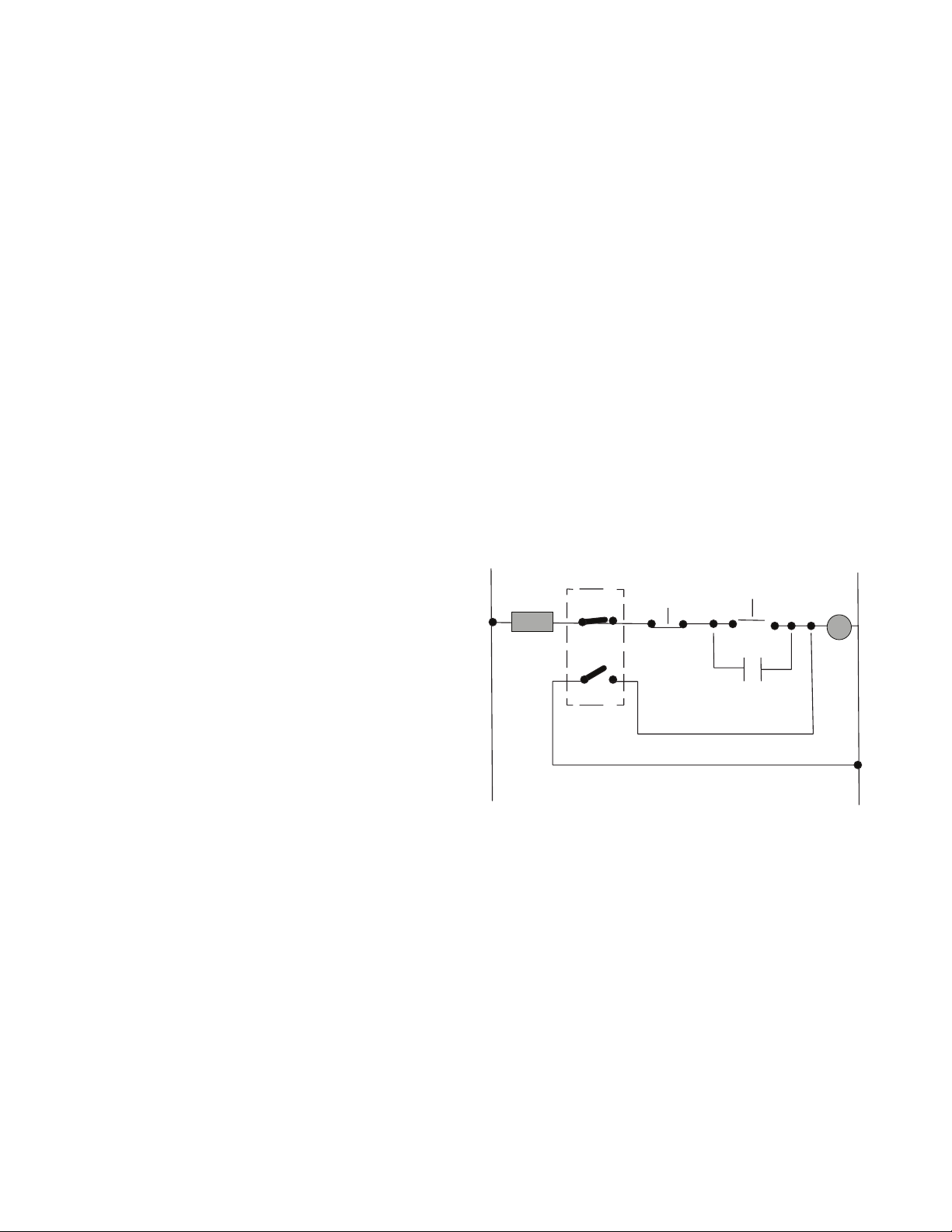
Safety Switch Contacts with Key Installed
Fuse
11 12
Stop
23 24
Start
M
L2
M
Operational
Temperature: -30ºC/+80ºC (-22ºF/+176ºF)
Contact 1 N.O. -1 N.C. with forced
Type: disconnect of N.C. contacts
Special wiring for the safety-interlock switch to
prevent tampering. The N.O. contact 23-24 short
circuits the coil of the motor starter (M) with key
Mechanical
Life: 1 million switch operations
removed. If the N.C. contact 11-12 were jumpered,
the fuse would blow when the key is removed from
the switch and an attempt is made to restart the
Protection: IP 65/Nema 4
Termination: 4 screw terminal connections M3.5
screws
2 Warner Electric • 800-825-9050 P-2025-WE • 11/12
circuit.
Note: Fuse to be 10 Amp slow acting or 16
Amp fast acting type.
Page 3

Actuation Directions
On Off
A
Extended
• 4 approach directions by changing the cap’s position A or B.
• Cover 1. has to be opened before changing cap 2.
• Insert the scewdriver point into the separable gap housing and rotate screwdriver (until the
cap unlocks) 3.
• Remove the cap and according to picture 4 turn around 180º to put into housing and close
the cover to lock cap.
• Radical actuation will reduce the mechanical life of the switch. Observe the minimum radius
as shown in the Actuator Mounting directions.
• Unused key slots covered with plastic insert.
Switching Diagram
11 12
23
24
Contact Operation
ctuator
mm
20.5
3.2
2.4
Retracted
23-24
11 - 12
3.4
Warner Electric • 800-825-9050 P-2025-WE • 11/12 3
Page 4

Mechanical/Dimensions mm
m x .0394 = inches
4 Warner Electric • 800-825-9050 P-2025-WE • 11/12
Page 5

Actuator Mounting
Warner Electric • 800-825-9050 P-2025-WE • 11/12 5
Page 6

Warranty
Warner Electric LLC warrants that it will repair or replace (whichever it deems advisable) any product manufactured and sold
by it which proves to be defective in material or workmanship within a period of one (1) year from the date of original purchase
for consumer, commercial or industrial use.
This warranty extends only to the original purchaser and is not transferable or assignable without Warner Electric LLC’s prior
consent.
Warranty service can be obtained in the U.S.A. by returning any defective product, transportation charges prepaid, to the
appropriate Warner Electric LLC factory. Additional warranty information may be obtained by writing the Customer Satisfaction
Department, Warner Electric LLC, 449 Gardner Street, South Beloit, Illinois 61080, or by calling 815-389-3771.
A purchase receipt or other proof of original purchase will be required before warranty service is rendered. If found defective
under the terms of this warranty, repair or replacement will be made, without charge, together with a refund for transportation
costs. If found not to be defective, you will be notified and, with your consent, the item will be repaired or replaced and
returned to you at your expense.
This warranty covers normal use and does not cover damage or defect which results from alteration, accident, neglect, or
improper installation, operation, or maintenance.
Some states do not allow limitation on how long an implied warranty lasts, so the above limitation may not apply to you.
Warner Electric LLC’s obligation under this warranty is limited to the repair or replacement of the defective product and in no
event shall Warner Electric LLC be liable for consequential, indirect, or incidental damages of any kind incurred by reason of
the manufacture, sale or use of any defective product. Warner Electric LLC neither assumes nor authorizes any other person
to give any other warranty or to assume any other obligation or liability on its behalf.
WITH RESPECT TO CONSUMER USE OF THE PRODUCT, ANY IMPLIED WARRANTIES WHICH THE CONSUMER MAY
HAVE ARE LIMITED IN DURATION TO ONE YEAR FROM THE DATE OF ORIGINAL CONSUMER PURCHASE. WITH
RESPECT TO COMMERCIAL AND INDUSTRIAL USES OF THE PRODUCT, THE FOREGOING WARRANTY IS IN LIEU
OF AND EXCLUDES ALL OTHER WARRANTIES, WHETHER EXPRESSED OR IMPLIED BY OPERATION OF LAW OR
OTHERWISE, INCLUDING, BUT NOT LIMITED TO, ANY IMPLIED WARRANTIES OF MERCHANTABILITY OR FITNESS.
Some states do not allow the exclusion or limitation of incidental or consequential damages, so the above limitation or
exclusion may not apply to you. This warranty gives you specific legal rights and you may also have other rights which vary
from state to state.
Changes in Dimensions and Specications
All dimensions and specifications shown in Warner Electric catalogs are subject to change without notice. Weights do not
include weight of boxing for shipment. Certified prints will be furnished without charge on request to Warner Electric.
Warner Electric
31 Industrial Park Road • New Hartford, CT 06057
800-389-3771 • Fax: 815-389-2582
www.warnerelectric.com
Printed in USAP-2025-WE • Part # 601-6119-016 11/12
 Loading...