

Page 1
SF-500, SF-650, SFC-500,
SFC-650, SFPBC-500, SFPBC-650 Pin
Drive Armature & Spline Drive Armatures
P-202
819-0482
Installation & Operating Instructions
Page 2
Contents
Installation Instructions
SFC-500 SFC-650 Pin Drive . . . . . . . . . . . . . . . . .3
SFC-500 Spline Drive . . . . . . . . . . . . . . . . . . . . . . .7
SF-500 SF-650 . . . . . . . . . . . . . . . . . . . . . . . . . . . .8
SFPBC-500 Spline Drive . . . . . . . . . . . . . . . . . . .11
SFPBC-500 SFPBC-650 Pin Drive . . . . . . . . . . .14
Torque Tabs . . . . . . . . . . . . . . . . . . . . . . . . . . . . . . .18
Conduit Box Installation . . . . . . . . . . . . . . . . . . . . .19
Electrical Coil Data . . . . . . . . . . . . . . . . . . . . . . . . .21
Burnishing and Maintenance . . . . . . . . . . . . . . .22-23
Illustration Drawings
SF-500 Bearing Mounted . . . . . . . . . . . . . . . .24-25
SF-650 Flange Mounted . . . . . . . . . . . . . . . . .26-27
SF-650 Bearing Mounted . . . . . . . . . . . . . . . .28-29
SFC-500 Normal Duty Clutch Coupling . . . . .30-31
SFC-500 Heavy Duty Clutch Coupling . . . . . .32-33
SFC-650 Flange Mounted Clutch
Coupling . . . . . . . . . . . . . . . . . . . . . . . . . . . . .34-35
SFC-650 Bearing Mounted Clutch
Coupling . . . . . . . . . . . . . . . . . . . . . . . . . . . . .36-37
SFPBC-500 Normal Duty Clutch/Brake
Coupling . . . . . . . . . . . . . . . . . . . . . . . . . . . . .38-39
SFPBC-500 Heavy Duty Clutch/Brake
Coupling . . . . . . . . . . . . . . . . . . . . . . . . . . . . .40-41
SFPBC-650 Clutch Brake Coupling . . . . . . . .42-43
Bushing Part Numbers . . . . . . . . . . . . . . . . . . . .44-45
Warranty . . . . . . . . . . . . . . . . . . . . . . . . . Back Cover
Failure to follow these
instructions may result in product damage,
equipment damage, and serious or fatal injury to
personnel.
Follow the installation instructions in this manual
care ful ly to ensure safe, reliable operation. All
stated or implied manufacturer warranties are
voided if this product is not installed in accordance
with these instructions.
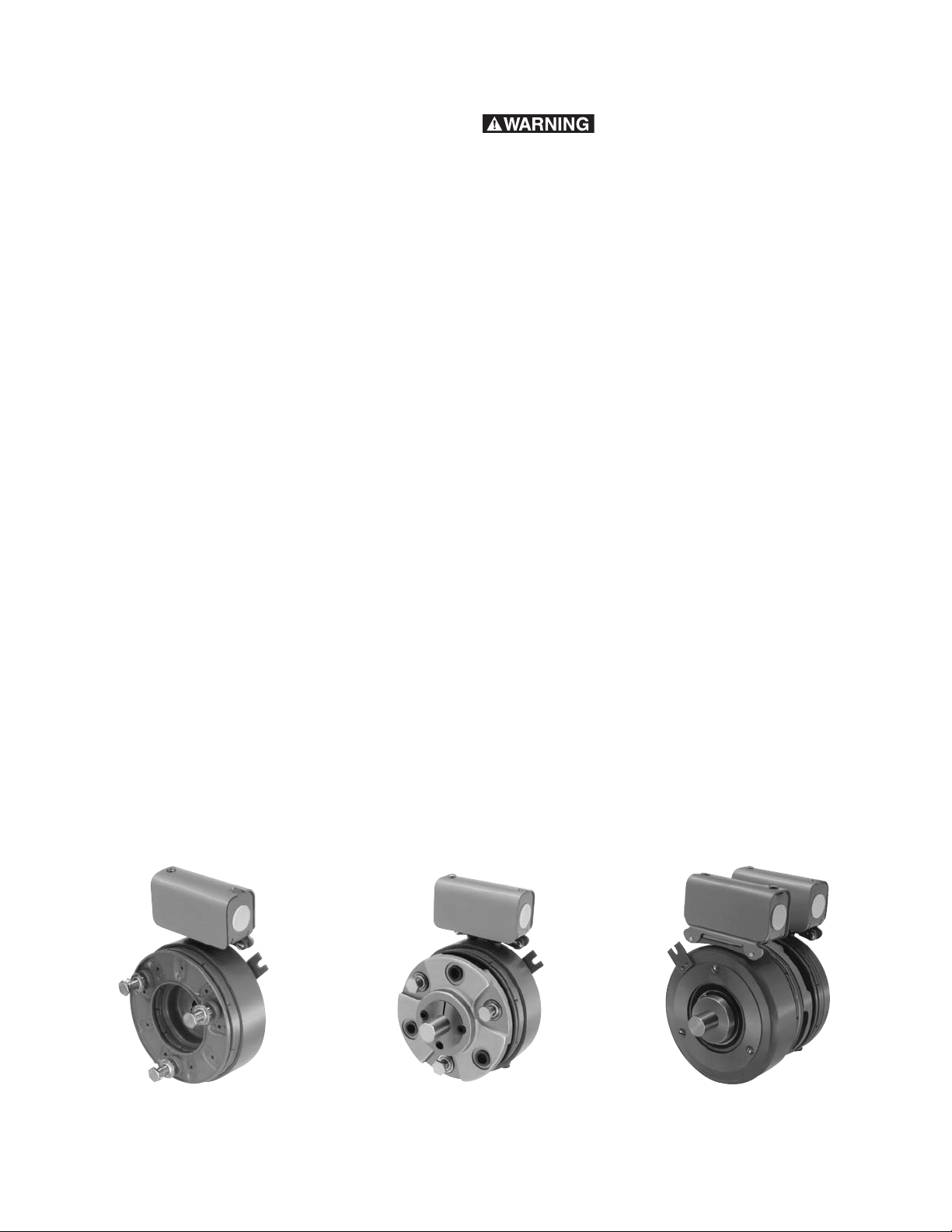
SF-500 SFC-500 SFPBC-500
Pin Drive
Warner Electric • 800-825-9050 P-202-01 • 819-0482
2
Page 3
SFC-500 SFC-650
Clutch-Coupling Pin Drive Armatures
The illustration drawings, parts lists, and exploded
views for these units can be found on pages 30, 31 and
34 thru 37.
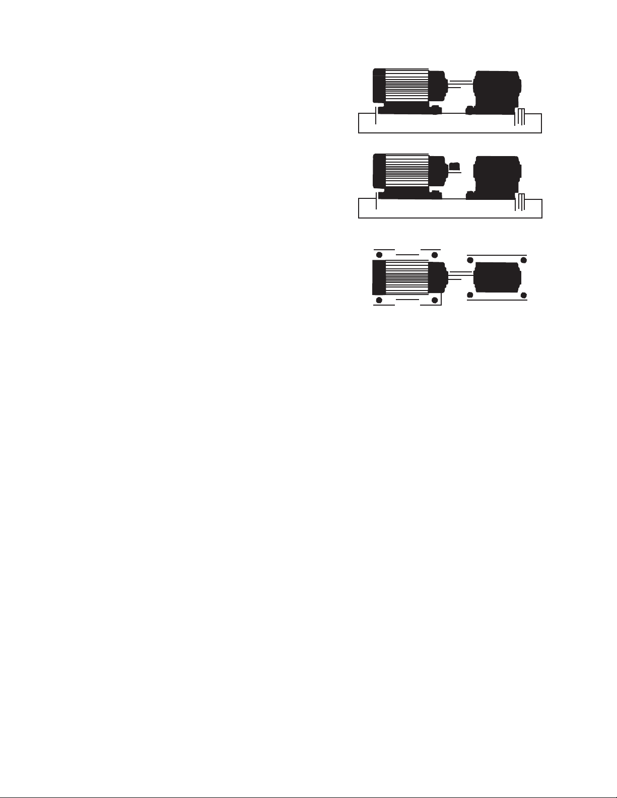
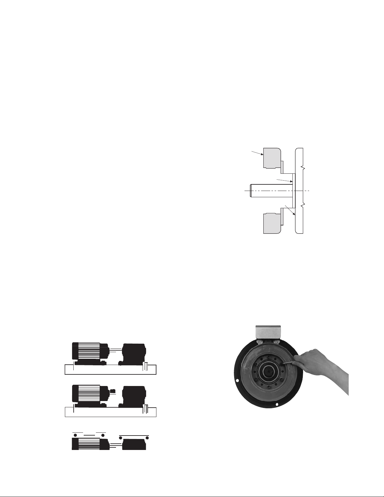
A. Aligning the Shafts
In order for the clutch-coupling unit to operate
properly, the mounting shafts of the motor and
reducer or other hardware must be aligned with respect
to each other before the unit is installed. The two shafts
should be con cen tric with each other within .004 T.I.R.,
and angular alignment should be within 1/2 degree.
(Figure 1)
1. Use a straight-edge to check if the shafts are
aligned with each other. For a more precise
indication of align ment, use a dial indicator.
2. Adjust the position of the motor, reducer, or
other hardware as required to achieve the correct align ment.
3. To be sure the shafts stay in alignment, drill
holes for tapered dowel pins through the
mounting bases of the motor, reducer, or other
hardware and into the mounting surfaces. This
procedure will ensure that, after the clutch-coupling has been installed, the shafts can easily
be placed in proper alignment again by lining
up the holes and secured by inserting the dow el pins.
B. Installing the Conduit Box
Install the conduit box on the field. Instructions for this
procedure are supplied with conduit box.
C. Mounting the Field-and-Rotor Assembly
Either the field-and-rotor assembly or the
armature-and-hub assembly can be installed first,
depending on the char ac ter is tics of each application.
The SFC-500 clutch-couplings are bearing-mounted
units. The SFC-650 units are either bearing-mounted or
flange-mounted.
Figure 1
Bearing Mounted Units
In bearing-mounted units, the field and rotor are
shipped as an assembly. Step 1 applies only to the
SFC-650 units. Steps 2-5 apply to both the SFC-650
and SFC-500.
1. The SFC-650 field and rotor assemblies are
mounted on the shaft with a taperlock bushing.
Insert the bush ing into the ta pered bore, lining
up the clearance holes in the bushing flange
with the tapered holes in the rotor hub.
2. Insert a key into the keyway in the bore of the
rotor and slide the assembly onto the shaft.
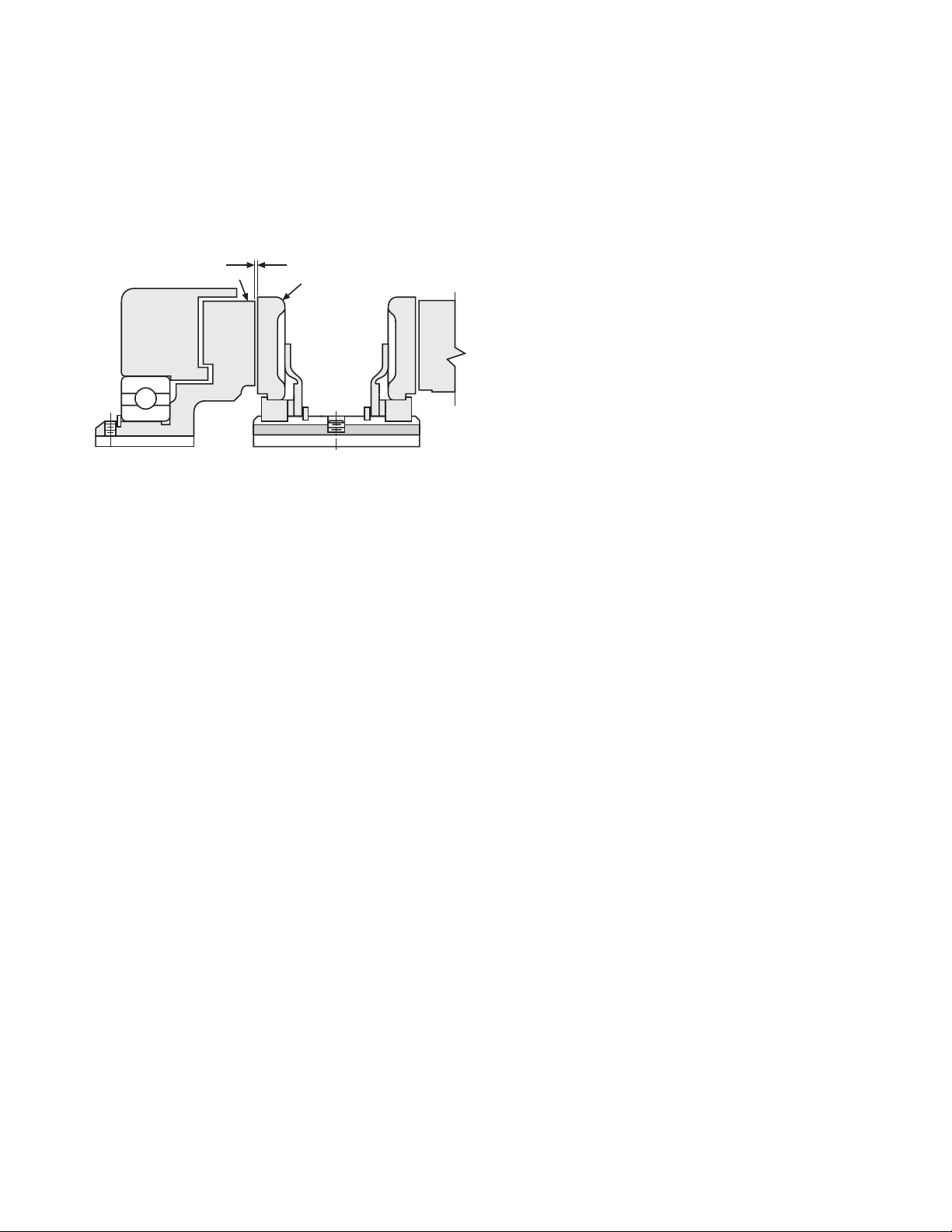
3. If the armature has been secured to the shaft
first, then adjust the rotor’s position to allow
ap prox i mate ly 1/32-inch between the two faces.
(Figure 11)
4. Secure the assembly on the shaft by alternately
tight en ing the two screws.
5. A tab or torque arm is provided to prevent the
field from rotating with the shaft. Insert either a
pin in the U-slot or a fork around the torque arm
to prevent this rotation. Under no circumstances, however, should the field be so tightly
restrained that is preloads the bearing. For more
information on torque tabs, see page 18.
Warner Electric • 800-825-9050 P-202-01 • 819-0482
3
Page 4
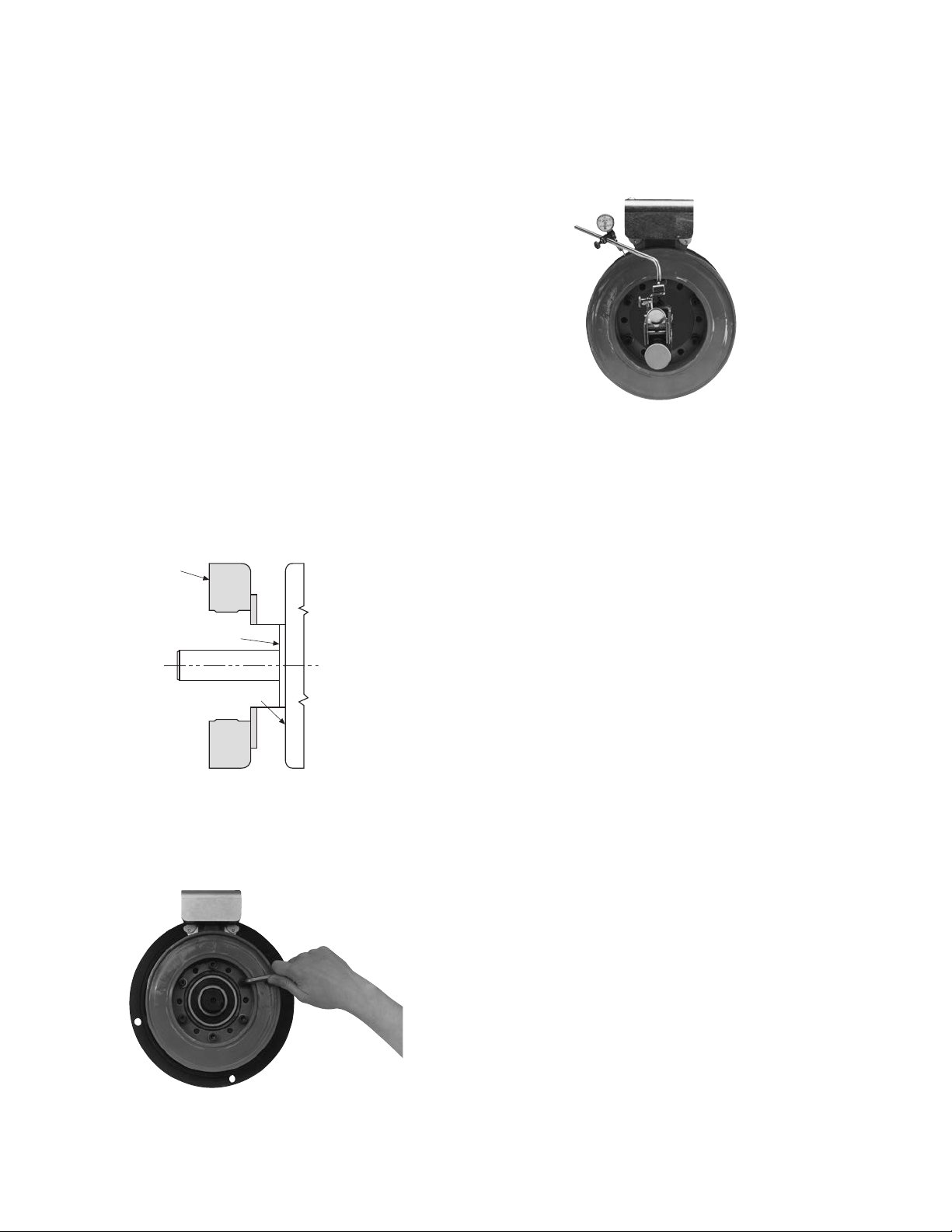
Flange-Mounted Units
Field
Pilot Diameter
Mounting Surface
The fields and rotors are shipped separately for
flange mounted units. On some applications it will be
nec es sary to mount the rotor first, and then bring the
field into position. In other instances the field will be
mounted first, and then the rotor (mounted on a shaft)
will be inserted into place.
In either case, the rotor and field must be
positioned in accordance with the overall axial
dimension from the face of the rotor to the back of
the field flange as shown on the illustration drawings
(dimension “L,” page 34). Hold ing this dimension will
assure the proper axial clearance between the field
and the rotor.
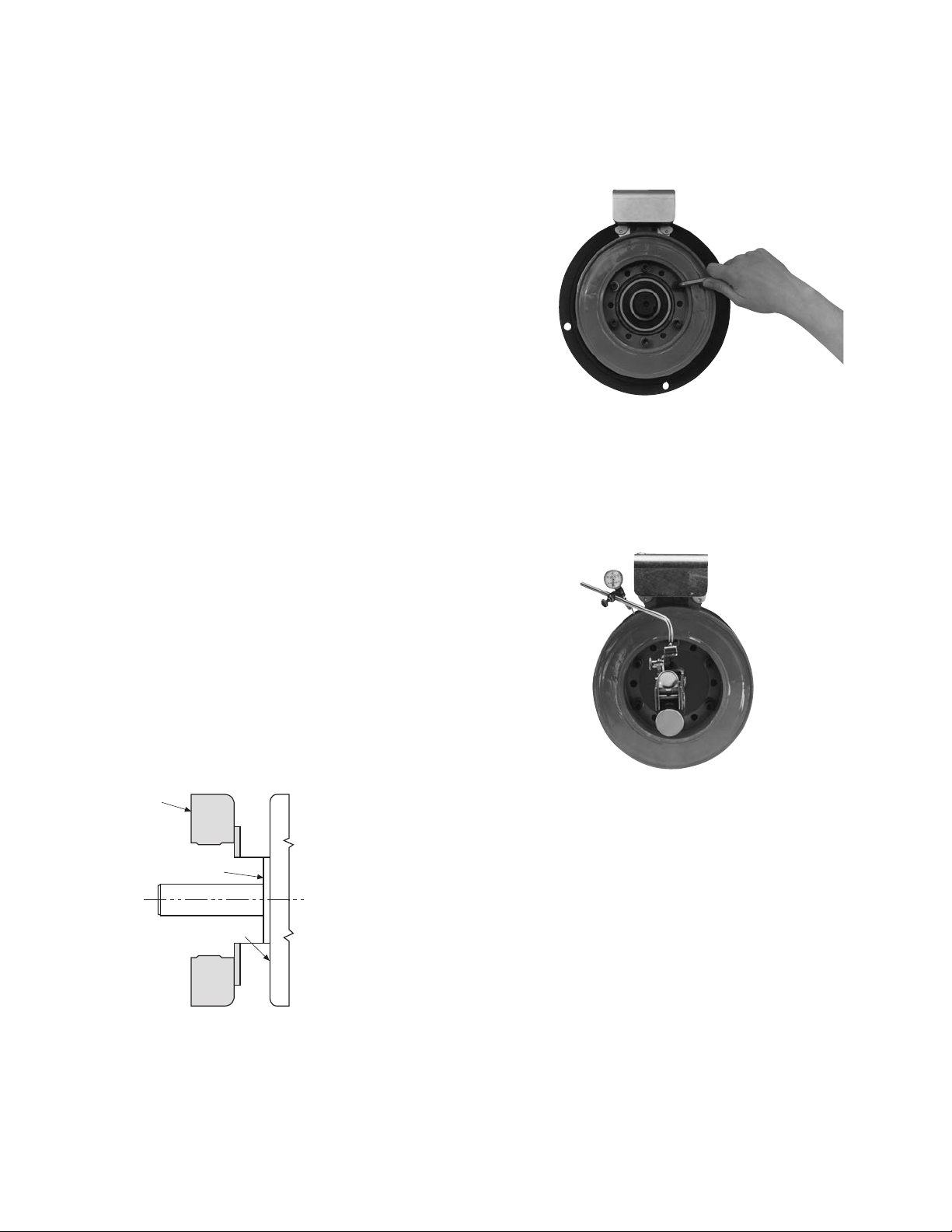
1. Care must be taken in selecting the location
for mount ing the field assembly. Pilot diameters are ma chined on the field mounting flange
to aid in holding the field in the proper position.
2. An appropriate pilot diameter must be
provided on the mounting surface as well.
(Figure 2)
3. The field assembly is then fastened in place
with capscrews and lockwashers. (Figure 3)
Figure 4
4. Once the unit is in place, it must be square
and con cen tric with the shaft in accordance
with the tol er anc es listed on the drawings.
(Figure 4)
Figure 2
5. The rotor is mounted on the shaft with a
taperlock bushing. Insert the bushing
into the tapered bore.
6. Loosely assemble the two locking screws
between the bushing and the rotor.
7. Insert the key into the shaft keyway, and slide
the rotor assembly over the key and on to the
shaft.
8. Adjust the rotor’s position to achieve the overall axial dimension “L” (page 34) when the
bushing is se cured.
9. Secure the assembly in this position by
alternately tightening the two locking screws.
Figure 3
Warner Electric • 800-825-9050 P-202-01 • 819-0482
4
Page 5
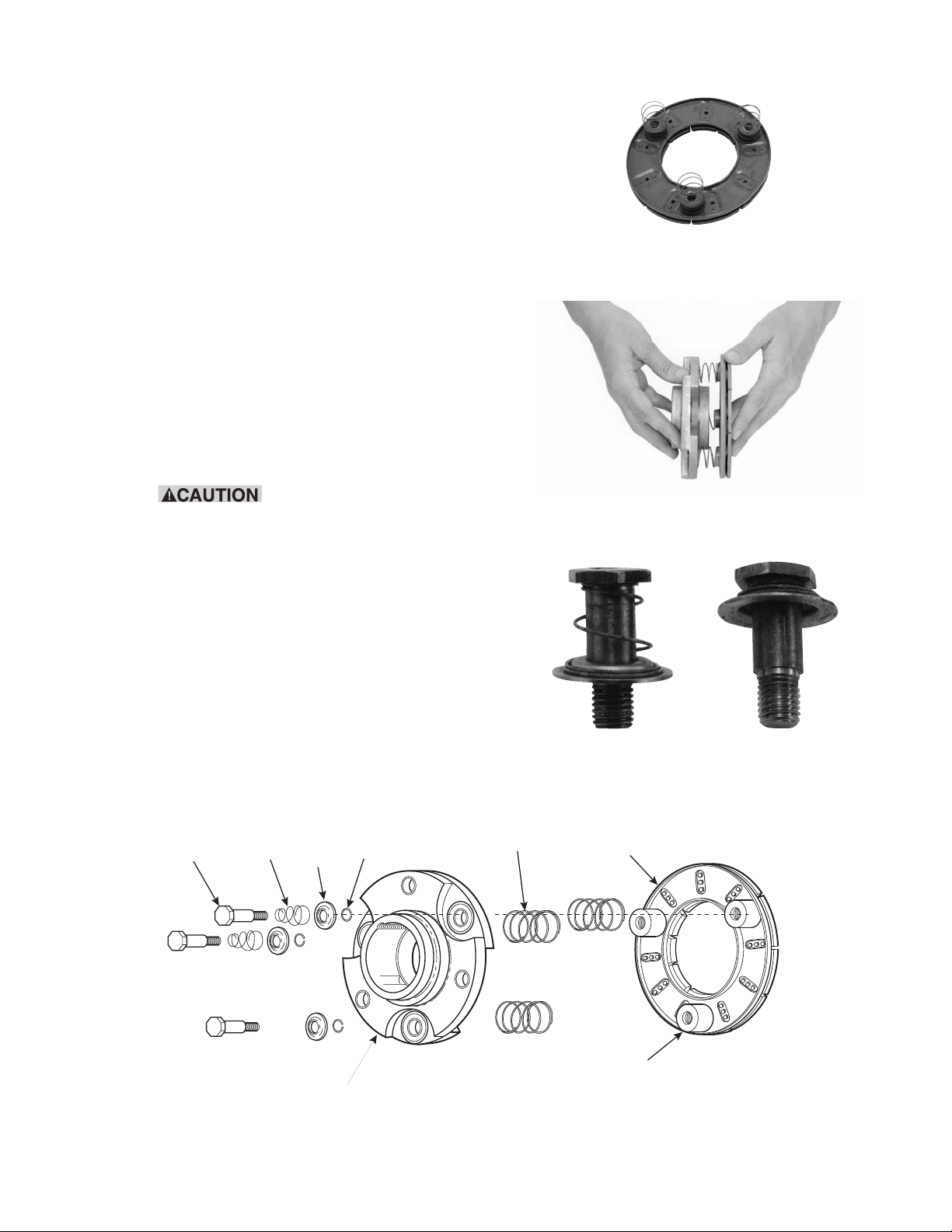
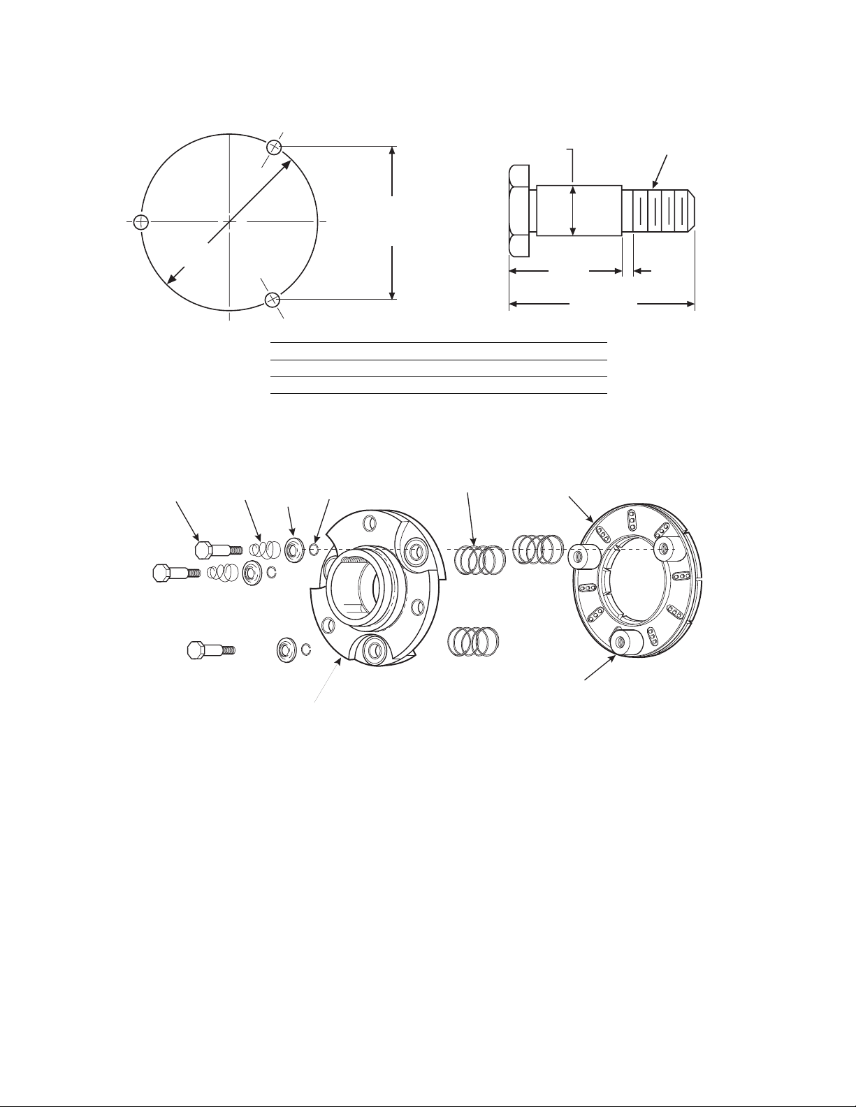
D. Assembling the Armature and Hub
Drive Pin
Conical
Spring
Retainer
Detent
Spring
Straight
Spring
Armature
Armature
Hub
Armature
Boss
Assemble the armature to the armature hub with the
autogap mounting accessory. The hub is reversible.
The side on which the armature is mounted will
depend on the direction in which the taperlock bushing must enter.
The autogap assembly is a double spring device
which allows for automatic armature clearance and
adjustment for wear. The smaller or conical spring
pushes the ar ma ture from the rotor face, leaving a
gap of about 1/32 inch, while the straight spring automatically follows up for wear. This combination maintains maximum performance ef fi cien cy throughout the
life of the unit.
The assembly procedure for the autogap accessory
is as follows. (Figure 5)
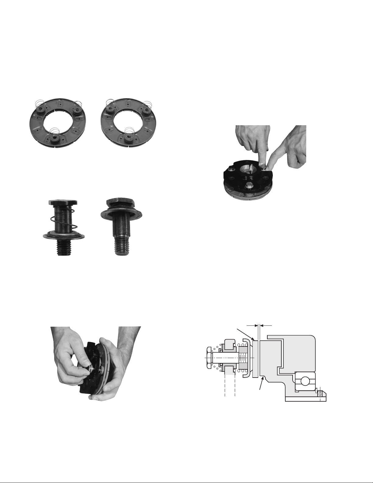
Step 1 Place the straight springs over the armature
bosses on the back side of the armature.
(Figure 6)
Step 2 Place the
armature hub over the
straight springs.
Figure 6
Figure 7
The straight springs must fit into the grooves
in the
armature hub. (Figure 7)
Step 3 Compress the conical springs against the
retainer rings by sliding the detent springs
toward the head of the pins.
(All pins) (Figure 8)
Step 4 Insert the assembled drive pins through the
armature hub and straight springs and into
the threaded armature boss es. Apply grade
Figure 8
Figure 5
Warner Electric • 800-825-9050 P-202-01 • 819-0482
5
Page 6
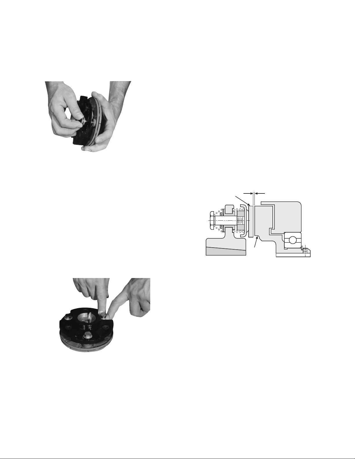
from burrs and chips before assembling.
Armature
1/32 inch Gap
Rotor
290 Loctite Sealant on the drive pin threads.
(Figure 9)
Step 5 Tighten the drive pins until the shoulders of
the pins are against the face of the armature
bosses. Since the threads are a class No. 3
Figure 9
fit, the pins may seem to bind.
Note: Alternately tighten each drive pin a
few turns at a time.
1. Place the bushing into the hub and insert the
key. The key is a side-to-side fit and should
not contact the top of the keyway.
2. Insert the locking setscrews loosely into the
bushing and slide the assembly onto the
shaft.
3. If the field-and-rotor assembly has been
secured to the shaft first, then adjust the
armature’s position to allow approxi-
mately 1/32-inch between the two fac es.
Once this 1/32-inch gap has been set, it will
be au to mat i cal ly maintained throughout the
life of the unit. (Figure 11)
4. Secure the armature’s position on the shaft by
al ter nate ly tightening each setscrew. During
the tight en ing process the bushing should
be tapped lightly to make sure it seats-in
properly.
Step 6 Compress the retainers against the armature
hub and check to see that the armature hub
is held tightly to the armature bosses. Note:
This position must not be dis turbed during
completion of assembly. (Figure 10)
E. Mounting the Armature Assembly
The armature assembly is mounted on the shaft with a
taperlock bushing. All parts must be clean and free
Figure 10
Figure 11
6
Warner Electric • 800-825-9050 P-202-01 • 819-0482
Page 7
SFC-500 Clutch Coupling Spline Drive
1/32 inch Gap
Rotor
Armature
Armature
D. Assembling the Armature and Hub
The illustration drawing, parts list, and exploded view
for this unit can be found on pages 32-33.
The SFC-500 clutch-couplings are bearing-mounted
units. Either the field-and-rotor assembly or the
ar ma ture-and-hub assembly can be installed first,
depending on the characteristics of each application.
A. Aligning the shafts
Before the clutch coupling can be installed, the
mount ing shafts of the motor and reducer or other
hardware must be aligned to each other. Follow the
instructions provided for the pin drive units on page 3.
B. Installing the Conduit Box
Installed the conduit box on the field assembly.
In struc tions for this procedure can be found on are
supplied with conduit box.
C. Mounting the Field-and-Rotor
Assembly
The clutch-coupling units contain spline drive armatures and hubs. The armatures are shipped with a
built-in autogap spring accessory. This device automatically maintains a gap of about 1/32'' between the
armature and magnet faces for the life of the unit.
(Figure 3)
These units are shipped with the armature and
autogap already assembled. Follow these instructions
to as sem ble the splined armature assembly and hub:
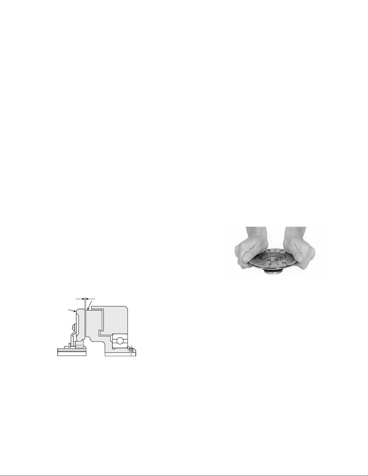
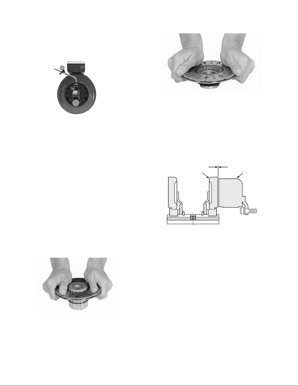
Step 1 Place the splined hub on a flat surface. The
extended portion of the hub, where the set
screw holes are lo cat ed, should be down.
Step 2 Check the detent ring in the armature
assembly to make sure it is centered evenly
around the spline. This ring moves freely,
but it should be centered for easier as sem bly of the hub.
Step 3 Holding the armature with the segmented
side up, press the armature onto the splined
hub. This is most easily done by applying
firm back-and-forth pressure. (Figure 2)
Step 4 Push the assembly up against the retainer
ring.
1. Insert a key into the keyway in the bore of the
rotor, and slide the assembly onto the shaft.
2. If the armature has been secured to the shaft
first, then adjust the rotor’s position to allow
ap prox i mate ly 1/32-inch between the two
faces. (Figure 3)
Figure 3
3. Secure the assembly on the shaft by
alternately tight en ing the two setscrews.
4. A tab or torque arm is provided to prevent the
field from rotating with the shaft. Insert either
a pin in the U-slot or a fork around the torque
arm to prevent this rotation. Under no
circumstances, however, should the field be
so tightly restrained that it preloads the bearing. For more information on torque tabs, see
page 18.
Figure 2
E. Mounting the Armature-Hub Assembly
1. Insert a key in the keyway of the hub and
slide the armature-hub assembly on to the
shaft.
2. If the field-and-rotor assembly has been
se cured to the shaft first, then adjust the
armature’s position to allow a 1/32-
inch gap between the two faces. (Fig ure 3)
3. Secure the armature-hub assembly in this
po si tion by tightening the two setscrews in
the hub.
4. Check the assembly by pressing the armature
into contact with the rotor face and then
releasing it. The armature should spring back
about 1/32''. This gap will be automatically
maintained for the life of the unit.
Warner Electric • 800-825-9050 P-202-01 • 819-0482
7
Page 8
SF-500 SF-650 Clutch Pin Drive Armature
The illustration drawings, parts lists, and exploded
views for these units can be found beginning on
pages 24 to 29.
A. Installing the Conduit Box
Install the conduit box on the field assembly.
In struc tions are supplied with conduit box.
B. Mounting the Field-and-Rotor
Assembly
Follow the instructions provided for the SFC-500 and
SFC-650 units, Section C, page 3, for mounting the
field-and-rotor assemblies.
within .006 T.I.R.
2. Once the pulley, gear, etc., has been adapted
to the armature according to the above directions, the ar ma ture may be mounted to it
using the autogap ac ces so ry.
3. The autogap assembly is a double spring
device which allows for automatic armature
clearance and ad just ment for wear. The smaller or conical spring pushes the armature from
the rotor face, leaving a gap of about 1/32
inch, while the straight spring au to mat i cal ly
follows up for wear. This combination maintains maximum per for mance efficiency through out the life of the unit.
Figure 4
C. Assembling the Armature
1. A customer may wish to use the autogap
ac ces so ry to mount a clutch armature to his
own pulley, hub, gear, etc. Follow the illustrated dimensions to prop er ly adapt these parts
to the armature.
a. The chordal dimension must be held for
all chords between pin holes.
b. Sleeve bearings (Oilite Bronze) with an I.D.
of .376 ±.001 must be provided in the
holes of pulley or hub at the chordal and
bolt circle dimensions shown be low.
(Fig ure 5)
c. The drive pins must be square with the
plane of the mounting surface and magnet
Warner Electric • 800-825-9050 P-202-01 • 819-0482
8
Page 9
B
.3665 .0005 DIA.
A
1/16
63/64
1-11/32
5/16 - 24 UNF - 3A
Threads
Machining Instructions for Gear, Sprocket, or Pulley
Drive Pin
Conical
Spring
Retainer
Detent
Spring
Straight
Spring
Armature
Armature
Hub
Armature
Boss
AB
SF-500 3.875 ± .001 3.356 ± .001
SF-650 5.125 ± .001 3.624 ± .001
Figure 5
Figure 6
Warner Electric • 800-825-9050 P-202-01 • 819-0482
9
Page 10
The assembly procedure for the autogap accessory is
Armature
1/32 inch Gap
Rotor
as follows (see Figure 6):
Step 1 Place straight springs over armature bosses
on back side of armature. (Figure 7)
Figure 7
Step 2 Compress conical spring against retainer
ring by sliding detent spring towards head
of pin. (All pins). (Figure 8)
Step 4 Tighten drive pins until shoulders of pins
are against face of armature bosses. Since
threads are class No. 3 fit, pins may seem
to bind.
Step 5 Compress the retainer rings against the
armature hub (or customer-supplied part),
and check to see that the part is held
tightly to the armature bosses. Note: This
po si tion must not be disturbed during
completion of as sem bly. (Figure 10)
Figure 10
Figure 8
Step 3 Insert assembled drive pins through
armature hub (or customer-supplied part),
through the straight springs, and into the
threaded armature bosses. Apply grade 290
Loctite Sealant on drive pin threads.
(Figure 9)
D. Mounting the Armature Assembly
1. Slide the armature assembly onto the shaft.
2. If the field-and-rotor assembly has been
secured to the shaft or a machine member
first, then adjust the armature’s position to
allow approximately 1/32-inch between the
two faces.
Once this 1/32-inch gap has been set, it will
be au to mat i cal ly maintained throughout the
life of the unit. (Figure 11)
10
Figure 11
Figure 9
3. Secure the assembly in this position on the
shaft.
Warner Electric • 800-825-9050 P-202-01 • 819-0482
Page 11
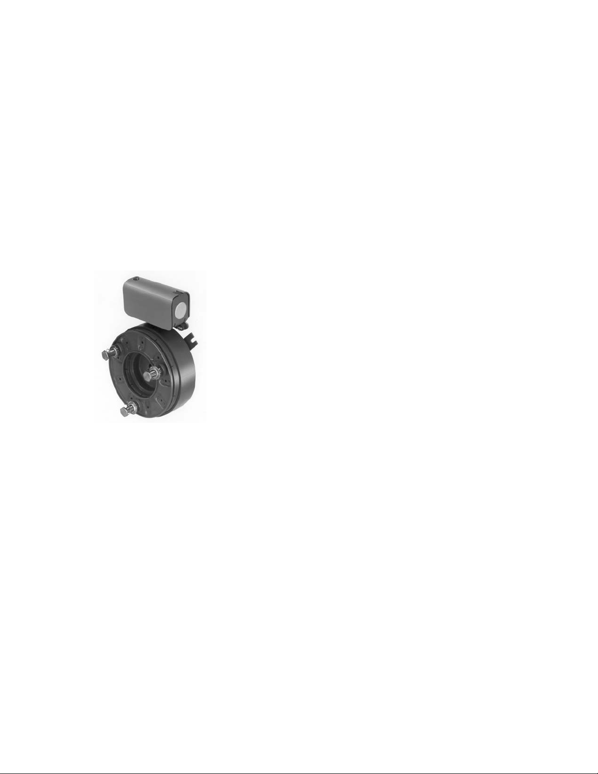
SFPBC-500 Spline Drive Armature
Field
Pilot Diameter
Mounting Surface
Clutch/Brake Coupling
C. Mounting the Magnet
This illustration drawing, parts list, and exploded
view for this unit can be found on page 40 and 41.
A. Aligning the Shafts
In order for the clutch-coupling unit to operate
properly, the mounting shafts of the motor and the
reducer or oth er hardware must be aligned with
respect to each other before the unit is installed.
The two shafts should be con cen tric with each
other within 004 T.I.R., and angular align ment
should be within 1/2 degree.
1. Use a straight edge to check if the shafts
are aligned with each other. For a more precise indication of align ment, use a dial indicator.
2. Adjust the position of the motor, reducer, or
other hardware as required to achieve the
correct align ment.
3. To be sure the shafts stay in alignment, drill
holes for tapered dowel pins through the
mounting bases of the motor, reducer, or
other hardware and into the mounting
surfaces. This procedure will ensure that,
after the clutch-coupling has been installed,
the shafts can easily be placed in proper
alignment again by lining up the holes and
secured by inserting the dow el pins.
The brake half of the clutch/brake unit is usually
installed first; however, in some cases it may be necessary to start with the clutch portion of the unit to
assure a proper as sem bly when complete.
The brake magnet is mounted to a stationary machine
member by a flange. Extreme care must be taken in
se lect ing the location for the mounting of the magnet.
Prop er positioning is very important for the unit to
function cor rect ly.
1. A pilot diameter on the mounting surface is
essential to hold the magnet within the
required tolerances. (Figure 2)
Figure 2
2. A machined pilot diameter is provided on the
magnet mounting flange (refer to illustration
drawings page 40) to aid in the proper
positioning of the magnet.
B. Installing the Conduit Boxes
Install a conduit box on the brake magnet and on
the clutch field. Instructions for this procedure are
supplied with a conduit box.
3. Once the mounting surface has been prepared, the magnet is bolted in place with capscrews and lockwashers. (Figure 3)
Figure 3
Figure 1
Warner Electric • 800-825-9050 P-202-01 • 819-0482
11
Page 12
4. Use a dial indicator to check the unit for
1/32 inch Gap
Magnet
Armature
con cen tric i ty and squareness to the
shaft. The unit should be concentric within
.010 T.I.R. and square within .006 T.I.R. (Figure
Figure 4
Figure 6
5. Turn the hub over and repeat Steps 3 and 4
with the other armature. (Figure 6)
4)
D. Assembling the Hub and Armatures
The heavy duty units contain spline drive armatures
and hubs. The armatures are shipped with a built-in
autogap spring accessory. This device automatically
maintains a gap of about 1/32'' between the armature
and magnet faces for the life of the unit.
Use the following method to assemble the armature
and splined hub:
1. Place the armature hub up on one end.
2. Check the detent ring in the armature
assembly to make sure it is evenly centered
around the spline. This ring moves freely, and
it should be centered for eas i er assembly of
the hub.
3. Holding one of the armatures with the
E. Mounting the Armature-Hub Assembly
1. Insert a key in the keyway of the hub and
slide the armature-hub assembly on to the
shaft.
Figure 7
2. Position the assembly so that the face of the
ar ma ture is about 1/32-inch from the magnet
face. (Figure 7)
3. Secure the armature-hub assembly in this
position by tightening the two setscrews in
the hub.
4. Check the assembly by pressing the armature
into contact with the magnet face and then
Figure 5
segmented side up, press the armature on to
12
the hub using firm back-and-forth pressure.
(Figure 5)
4. Push the assembly up against the retainer
ring.
Warner Electric • 800-825-9050 P-202-01 • 819-0482
Page 13
releasing it. The armature should spring back
1/32 inch Gap
Armature
Rotor
about 1/32''. This gap will be automatically
maintained for the life of the unit.
F. Mounting the Field-and-Rotor Assembly
1. Insert a key into the keyway in the bore of the
Figure 8
rotor, and slide the assembly onto the shaft.
2. Adjust the rotor’s position on the shaft to
allow ap prox i mate ly 1/32'' gap between the
faces of the rotor and armature. (Figure 8)
3. Secure the assembly on the shaft by
alternately tight en ing the two setscrews.
4. Set the autogap by pressing the face of the
armature into the rotor face. When the
armature is released, it will spring back about
1/32''. Once this 1/32'' gap is set, it will be
automatically maintained throughout the life of
the unit.
5. A tab or torque arm is provided to prevent the
field from rotating with the shaft. Insert either
a pin in the U-slot or a fork around the torque
arm to prevent this rotation. Under no
circumstances, however, should the field be
so tightly restrained that it preloads the
bearing. For more information on torque tabs,
see page 18.
Warner Electric • 800-825-9050 P-202-01 • 819-0482
13
Page 14
SFPBC-500 & SFPBC-650 Clutch/Brake
Field
Pilot Diameter
Mounting Surface
Coupling Normal Duty Pin Drive Armature
The illustration drawings, parts lists, and exploded
views for these units can be found beginning on
pages 38, 39 and 42, 43.
The brake half of the clutch/brake unit is usually
installed first; however, in some cases it may be
necessary to start with the clutch portion of the
unit to assure a proper as sem bly when complete.
A. Aligning the Shafts
Before the clutch/brake coupling can be installed,
the mounting shafts of the motor and reducer or
other hard ware must be aligned to each other.
Follow the
in struc tions provided on page 11 for the spline drive
unit.
B. Installing the Conduit Boxes
Install a conduit box on the brake magnet and on
the clutch field. Instructions are supplied with a conduit box.
prepared, the magnet is bolted in place with
capscrews and lockwashers. (Figure 3)
4. Use a dial indicator to check the unit for
Figure 3
con cen tric i ty and squareness to the shaft.
The unit should be concentric within .010
T.I.R. and square within .006 T.I.R. (Figure 4)
C. Mounting the Magnet
The brake magnet is mounted to a stationary
machine member by a flange. Extreme care must be
taken in se lect ing the location for the mounting of
the magnet. Prop er positioning is very important for
the unit to func tion cor rect ly.
1. A pilot diameter on the mounting surface is
essential to hold the magnet within the
required tolerances. (Figure 2)
Figure 2
2. A machined pilot diameter is provided on the
magnet mounting flange (refer to illustration
drawings page 38 & 42) to aid in the proper
positioning of the mag net.
Figure 4
D. Assembling the Armature and Hub
Assemble the armature to the armature hub with the
autogap mounting accessory.
The autogap assembly is a double spring device
which allows for automatic armature clearance and
adjustment for wear. The smaller or conical spring
pushes the ar ma ture from the rotor face, leaving a
gap of about 1/32 inch, while the straight spring
automatically follows up for wear. This combination
maintains maximum performance ef fi cien cy throughout the life of the unit.
The assembly procedure for the autogap accessory
is as follows. (Figure 5)
3. Once the mounting surface has been
Warner Electric • 800-825-9050 P-202-01 • 819-0482
14
Page 15

Armature Boss
Armature Hub
Drive Pin
Conical
Spring
Retainer
Detnet Spring
Straight
Spring
Armature
Step 1 Place straight springs over armature bosses
on back side of both armatures (Figure 6).
Figure 6
Step 2 Compress conical spring against retainer
ring by sliding detent spring toward head of
pin. (All pins). (Figure 7)
Figure 7
Figure 5
Step 4 Insert the remaining drive pins from the
opposite side of armature hub through
remaining holes.
Note: Apply grade 290 Loctite Sealant
on the threads of all drive pins.
(Fig ure 9)
Figure 9
Step 5 Holding the pins in position, place the
armature hub over one armature.
Make sure the straight springs on the ar ma ture bosses fit into the grooves in the armature hub.
Step 3 Insert half of the compressed drive pins
through the ar ma ture hub. The threaded end
of the pins must come through on the side
of the hub with grooves around the holes.
(Figure 8)
Figure 10
Figure 8
Warner Electric • 800-825-9050 P-202-01 • 819-0482
15
Page 16

(Figure 10)
Armature
1/32 inch Gap
Magnet
Step 6 Tighten these drive pins until shoulders of
pins are against face of armature bosses.
Since threads are class No. 3 fit, pins may
seem to bind.
during com ple tion of the assembly.
(Figure 13)
E. Mounting the Armature Assembly
Note: Alternately tighten each drive pin a
few turns at a time.
Step 7 Repeat Steps 5 and 6 for the second
amature. (Figure 11)
Figure 11
Step 8 Compress the armature hub and one of the
armatures together until the armature hub
bottoms on the armature boss. Slide the
retainer on each pin down tightly against
the armature hub. (Figure 12)
Step 9 Turn the assembly over and repeat Step 8
for the second armature.
Note: This position must not be disturbed
The armature and armature hub are mounted on the
shaft with a taperlock bushing. All parts must be clean
and free from burrs and chips before assembling.
1. Place the bushing into the hub and insert the
key. The key is a side-to-side fit and should
not contact the top of the keyway.
2. Insert the locking setscrews loosely into the
bushing and slide the assembly onto the
shaft.
Figure 14
3. Place the face of the armature approximately
1/32'' from the face of the magnet. Once this
gap is set, it will be automatically maintained
throughout the life of the unit. (Figure 14)
16
4. Secure the armature’s position on the shaft
by al ter nate ly tightening each setscrew.
During the tight en ing process the bushing
Figure 12
Figure 13
Warner Electric • 800-825-9050 P-202-01 • 819-0482
Page 17

should be tapped lightly to make certain it
Rotor
1/32 inch Gap
Armature
1/32 inch Gap
seats in properly.
F. Mounting the Field-and-Rotor Assembly
1. Insert a key into the keyway in the bore of the
rotor, and slide the assembly onto the shaft.
2. Adjust the rotor’s position on the shaft to
Figure 15
allow ap prox i mate ly 1/32'' between the faces
of the rotor and armature. Secure the rotor in
this position by al ter nate ly tightening the two
locking screws. Once this 1/32'' gap is set, it
will be automatically maintained throughout
the life of the unit. (Figure 15)
3. Secure the assembly on the shaft by
alternately tight en ing the two setscrews.
4. A tab or torque arm is provided to prevent
the field from rotating with the shaft. Insert
either a pin in the U-slot or a fork around the
torque arm to prevent this rotation. Under no
circumstances, however should the
field be so tightly restrained that it preloads
the bearing. (For more information on torque
tabs, see page 18.)
Warner Electric • 800-825-9050 P-202-01 • 819-0482
17
Page 18

Torque Tabs
Clutches
Many Warner Electric clutch assemblies have a bearing
mounted stationary field. By design the bearing main tains its proper position between the field and rotor
mak ing it easy for the customer to mount the field-rotor
as sem bly. However, the bearing has a slight drag which
tends to make the field rotate with the rotor if not re strained. And, since the field has lead wires attached, it
must be restrained to prevent rotation and pulling of
these wires. To counteract this rotational force, the field
has a “torque tab” to which the customer must attach
an ap pro pri ate anti-rotational restraint.
A few hints regarding proper torque tab restraints are in
Figure 1
Rigid Member
order. First and foremost, it is important to recognize that
the force to be overcome is very small and the tab
should not be restrained in any manner which will preload the bearing. For example, if the clutch is mounted
with the back of the field adjacent to a rigid machine
member the customer should not attach a capscrew
tightly between the tab and the machine member. This
may pull the tab back against the rigid member as shown
in Figure 1 and preload the bearing. The recommended
methods are il lus trat ed in Figures 2, 3, and 4. The
method selected is primarily a matter of customer preference or con ve nience.
Figure 3
Pin in Hole
Loosely
Figure 2
Rigid Member
Straddling Tab
Figure 4
Flexible Strap
Warner Electric • 800-825-9050 P-202-01 • 819-0482
18
Page 19

Installation Instructions
4
10
8
11
12
7
3
6
5
9
9-1
2
1
4
Conduit Box Kit No. 5200-101-010
Description
This Warner Electric conduit box is designed to
provide a proper means for field wiring ter mi na tions.
It conforms to the requirements of Un der writ ers
Laboratories. Kit No. 5200-101-010, plus magnet
terminal accessory kit, con tains all components
needed to assemble a conduit box for the above
mentioned units. Please follow these in struc tions
carefully when installing this conduit box. Fail ure to
comply with these instructions could result in un safe
electrical connections.
Components
Parts List for Kit 5200-101-010
Item Quan. Part Name
11Bracket
21Screw, Hex, Washer Hd.
and Sems Conical Washer
31Box, Conduit
43Screw, Hex. Washer Hd.
51Plug, Protective
62Grommet, Wire
72Spacer, Terminal
82Cap, Terminal
91Screw, Hex. Washer Hd.
9-1 1 Terminal, Ring
10 1 Cover Assembly
*11 2 Screw No. 6 Brass
2 Screw No. 8 Brass
†12 2 Terminal, Ring
*The No. 6 screws are required on Sizes 375, 400,
and 475. All others use No. 8.
† Terminal Ring provided with terminal accessory
kit 5311-101-003, 5311-101-001 respectively,
supplied with mag nets.
Note: All mounting screws are self-tapping.
Warner Electric • 800-825-9050 P-202-01 • 819-0482
19
Page 20

Step 1 Fasten bracket (1) to the clutch or brake
with one No. 10-32 hex. washer head screw
and washer (2). The square projection on
the clutch or brake between the terminals is
to be assembled into the square hole in
the bracket. The bracket flange is
installed toward the back of the unit.
(See Figure 1)
Figure 1
Step 2 Assemble a 1/2" flexible conduit fitting into
the desired end of the conduit box (3). If the
grounding nut on this conduit fitting is
tightened after the conduit box is in stalled on the magnet or field, avoid using
excessive tap ping force, which could damage the mounting. (Step 6)
Step 3 Mount conduit box (3) to the bracket (1).
The con duit box flange must be toward the
back of the clutch or brake. Secure the box
with two No.10-32 hex. washer head screws
(4). (See Figure 2)
Figure 3
Step 5 Push two terminal spacers (7) through the
grom mets with the spacer flanged ends
inside the conduit box. (See Figure 3)
Step 6 Connect electric supply cable to the fitting
installed on the conduit box. Use D.C.
supply only.
Rigid conduit must not be con nect ed
directly to the box. A minimum of 12" of flexible
cable must be used. It is recommended that
flexible "UL" listed liquid-tight, me tal lic or
non-metallic conduit, meet ing local codes, be used
with appropriate fit tings. Flexible cable is required
to prevent side loading of bearing on bear ing
mounted clutches and brakes and possible
de for ma tion of the conduit box or com po nents
during assembly.
Step 7 Press protective plug (5) into the unused
conduit hole in the box.
Step 8 Slide one rubber cap (8) onto each of the
two supply conductors, small end first.
Figure 2
Step 4 Snap the two rubber grommets (6) into two
square holes in the bottom of the conduit
box. The grom met crowns should be in the
box and the rubber flanges should be on
both sides of the metal floor. (See Figure 3)
Warner Electric • 800-825-9050 P-202-01 • 819-0482
20
Connect the two supply con duc tors (with
rubber caps) to the magnet or field ter mi nals
using two No. 6 or No. 8 screws (11). Use
wire re tain ing ring terminals supplied with
the clutch or brake terminal accessory. The
stripped wires may be wrapped around the
screw between the wire terminal ring and
the screw head or other ring type terminals
such as "AMP" may be used. The screws
are then assembled through the terminal
spacers (7) and threaded into the clutch or
brake terminals.
Page 21

Electrical Coil Data
Unit Size SF-500 PB & PC-500
Voltage – DC 6 24 90 6 24 90
Resistance @ 20°C — Ohms 1.076 14.9 206.1 1.36 23.8 251.1
Current — Amperes 5.58 1.61 .44 4.4 1.01 .36
Watts 34 39 39 26 24 32
Coil Build-up — Milliseconds 82 85 90 84 87 93
Coil Decay — Milliseconds 40 40 40 38 35 30
Unit Size SF-650 PB-650
Voltage – DC 6 24 90 6 24 90
Resistance @ 20°C — Ohms 1.16 17.7 225 1.24 18.3 257.2
Current — Amperes 5.19 1.36 .4 4.84 1.31 .35
Watts 31 33 36 29 31 32
Coil Build-up — Milliseconds 110 115 120 100 105 110
Coil Decay — Milliseconds 50 50 50 50 50 50
Notes: Build-up time equals current to ap prox i mate ly 90% of steady state value and flux to 90%.
Decay time equals current to approximately 10% of steady state value and flux to 10%.
Approximately because current leads or lags flux by a small amount.
Warner Electric • 800-825-9050 P-202-01 • 819-0482
21
Page 22

Burnishing and Maintenance
Burnishing
Intimate metal to metal contact is essential between
the armature and the metal rings (poles) of the magnet
or rotor. Warner Electric clutches and brakes leave the
fac to ry with the friction material slightly undercut
to assure good initial contact.
Foreign Materials: If units are used on machinery
where fine, abrasive dust, chips or grit are dispelled
into the at mo sphere, shielding of the brake or clutch
may be nec es sary if maximum life is to be obtained.
Where units are used near gear boxes or
transmissions requiring frequent lubrication, means
should be pro vid ed to protect the friction surfaces
from oil and grease to pre vent serious loss of torque.
Normally, the desired wearing-in process occurs
nat u ral ly as the surfaces slip upon engagement. The
time for wear-in, which is necessary to obtain the
ultimate torque of the unit, will vary depending on
speed, load and cycle duty.
If maximum torque is required immediately after
in stal la tion, the unit should be burnished by
slipping the friction surfaces together at reduced
voltage. It is rec om mend ed that the burnishing be
done right on the application, if at all possible.
Burnishing at high speed will result in a smoother
wear-in pattern and reduce the time for burnishing.
The volt age should be set at approximately 30% or
40% of the rated value.
The unit should be cycled on and off to allow
sufficient time between slip cycles to prevent
overheating.
When a Warner Electric brake or clutch is properly
as sem bled and installed, no further servicing,
lubrication, or maintenance should be required
throughout the life of the unit.
Maintenance
Wear Pattern: Wear grooves appear on the
armature and magnet surfaces. This is a normal
wear condition, and does not impair functioning of the
unit. Normally, the magnet and armature, as a mating
pair, will wear at the same rate. It is the usual
recommendation that both components be replaced
at the same time.
Remachining the face of a worn armature is not
rec om mend ed. If a replacement armature is to be
used with a used magnet, it is necessary to
remachine the worn magnet face. In refacing a
magnet: (1) machine only enough material to clean up
the complete face of the magnet; (2) hold the face
within .005'' of parallel with the mounting plate; and
(3) undercut the molded facing material .002''.004'' below the metal poles.
Heat: Excessive heat and high operating
temperatures are causes of rapid wear. Units
therefore, should be ven ti lat ed as efficiently as
possible, especially if the ap pli ca tion requires fast,
repetitive cycle operation.
Oil and grease accidently reaching the friction
surfaces may be removed by wiping with a rag
dampened with a suitable cleaner, which leaves no
residue. In performing this operation, do not drench
the friction material.
If the friction materials have been saturated with oil
or grease, no amount of cleaning will be completely
ef fec tive. Once such a unit has been placed back in
service, heat will cause the oil to boil to the surface,
resulting in further torque loss.
Torque Loss: If a brake or clutch slips or loses torque
completely, the initial check should be the input
voltage to the field as follows:
90-Volt Series: Connect a DC voltmeter with a range
of 0-100 or more directly across the magnet or field
terminals. With the power on and the potentiometer turned up, a normal reading is 90 volts, although
85 to 95 is satisfactory. The reading should drop as
the potentiometer control is ad just ed
counterclockwise.
24-Volt Series: Use a DC voltmeter with a range of
0-30 volts or more. A normal reading is approximately
22-26 volts.
6-Volt Series: Use a DC voltmeter of approximately
0-15 volt range. A normal reading is from 5.5 to 6.5
volts.
The above checks normally are sufficient. Further
checks may be made as follows: a low range
ammeter, when connected in series with one magnet
lead, will normally in di cate approximately .40 amperes
for the 90 volt units, 1.0 ampere for the 24 volt, and
3.5 amperes for the 6 volt series. These readings are
with the power on and the potentiometer control in
the maximum position.
Ohmmeter checks should be made with the power off
and the circuit open (to be certain, disconnect one
lead to the magnet). Average resistance for the 90 volt
series is 220 ohms; for the 24 volt, 20 ohms; and for
the 6 volt series, 1.5 ohms. A very high or infinite
resistance read ing would indicate an open coil.
If the above checks indicate that the proper voltage
and current is being supplied to the magnet,
mechanical parts should be checked to assure that
they are in good op er at ing condition and properly
installed.
Warner Electric • 800-825-9050 P-202-01 • 819-0482
22
Page 23

SF-500 Bearing Mounted Clutch Drawing I-25715
45°
Armature View
3.750
See page 9 for details
on Drive Pin Mountings
Re mov able plug
in ends for 1/2"
conduit.
.062 When New
5.328
Max.
5.062
Dia.
Dia.
.968
Min.
2.062 Dia.
.625
.453
3.781
max.
1.546
1.234
.187
4.093
1.750
Dia.
.750
.218
3.156
2.781
For Bore & Keyway
sizes see chart.
Field View
Customer Shall Maintain:
1. Armature shafts to be concentric with rotor
mounting shaft within .006 T.I.R.
5.218
.125
1.343
1.593
2.093
.281
Bore and Keyway Di men sions
Rotor
Bore Dia. Keyway
.751/.750 .187 x .093
.876/.875
.9385/.9375
1.001/1.000 .250 x .125
1.126/1.125
1.251/1.250
Rotor Shaft .750 – 1.250
Static Torque 50 lb.ft.
Maximum Speed 4,000 RPM
Standard Voltage D.C. 6, 24, 90
All dimensions are nominal, unless otherwise noted.
Warner Electric • 800-825-9050 P-202-01 • 819-0482
23
Page 24

1
2
3-1
3-2
3-3
3-4
3
(Shipped Assem bled)
5
4
SF-500 Bearing Mounted Clutch
Item Description Part Number Qty.
1 Autogap Accessory 5200-101-009 3
2 Armature 5300-111-002 1
3 Field and Rotor Assembly 1
6 Volt – 3/4" Bore 5200-452-002
24 Volt – 3/4" Bore 5200-452-004
90 Volt – 3/4" Bore 5200-452-005
6 Volt – 7/8" Bore 5200-452-008
24 Volt – 7/8" Bore 5200-452-010
90 Volt – 7/8" Bore 5200-452-011
24 Volt – 15/16 " Bore 5200-452-016
90 Volt – 15/16" Bore 5200-452-017
6 Volt – 1" Bore 5200-452-020
24 Volt – 1" Bore 5200-452-022
90 Volt – 1" Bore 5200-452-023
6 Volt – 1-1/8" Bore 5200-452-026
24 Volt – 1-1/8" Bore 5200-452-028
90 Volt – 1-1/8" Bore 5200-452-029
6 Volt – 1-1/4" Bore 5200-452-032
24 Volt – 1-1/4" Bore 5200-452-034
90 Volt – 1-1/4" Bore 5200-452-035
3-1 Rotor 1
3/4" Bore 5200-751-002
7/8" Bore 5200-751-003
15/16" Bore 5200-751-004
1" Bore 5200-751-005
1-1/8" Bore 5200-751-006
1-1/4" Bore 5200-751-007
Item Description Part Number Qty.
3-2 Field & Bearing Assembly 1
6 Volt 5200-451-024
24 Volt 5200-451-026
90 Volt 5200-451-027
3-3 Ball Bearing 166-0110 1
3-4 Retainer Ring 748-0002 1
4 Conduit Box 5200-101-010 1
5 Terminal Accessory 5311-101-001 1
How to Order:
1. Specify Bore Size for Item 3.
2. Specify Voltage for Item 3.
Example:
SF-500 Clutch per I-25715 - 90 Volt 3/4" Bore
These units meet standards set forth in UL508 and are
listed under guide card #NMTR2, file #59164.
These units are CSA certified under file #LR11543.
Warner Electric • 800-825-9050 P-202-01 • 819-0482
24
Page 25

SF-650 Flange Mounted Clutch Drawing I-25749
Removable plug
in ends for 1/2"
conduit.
See page 9 for Details on
Armature View
3.750
Drive Pin mountings.
.062 when new
6.687
6.500
Max.
Dia.
Dia.
.453
.968
3.500
max.
.625
Max.
1.546
1
.656
.937
4.625
5/16-18
UNC-3A
2.822/2.820
pilot
dia.
4.375 Dia.
.358/.338 dia. (4)
holes equally
spaced on 7.250
dia.*
45°
Field View
(Inside & Outside Mounted)
5.750 max.
.358/.338 dia. (4)
spaced on 7.250
Customer Shall Maintain:
1. Concentricity of field mounting pilot diameter
with rotor mounting shaft within .006 T.I.R.
2. Squareness of field mounting face with shaft
within .006 T.I.R. measured at field mounting
bolt circle.
6.500
8.000
7.998
holes equally
dia.*
1.812
.578
Max.
* Mounting holes are within .010 of true position relative
to pilot diameter.
Shaft Size .500 – 1.625
Static Torque 95 lb.ft.
Maximum Speed 3,600 RPM
Standard Voltage D.C. 6, 24, 90
3. Rotor mounting pilot diameter must be
concentric with shaft within .006 T.I.R.
All dimensions are nominal, unless otherwise noted.
Warner Electric • 800-825-9050 P-202-01 • 819-0482
25
Page 26

SF-650 Flange Mounted Clutch
1
2
3
5
4
7
6A
6A-1
8
8
6B-1
6B
7
Item Description Part Number Qty.
1 Armature Accessory 5181-101-010 4
2 Armature 5281-111-002 1
3 Rotor Hub & Mounting Acc. 5207-101-005 1
4 Rotor 5281-751-001 1
5 Bushing*
1/2" to 1-5/8" Bore 180-0326 to 180-0344 1
6A Field - Inside Mounted 1
6 Volt 5207-451-009
24 Volt 5207-451-012
90 Volt 5207-451-011
6A-1 Terminal Accessory 5311-101-001 1
6B Field - Outside Mounted 1
6 Volt 5207-451-003
26
24 Volt 5207-451-006
90 Volt 5207-451-005
6B-1 Terminal Accessory 5311-101-001 1
7 Mounting Accessory 5321-101-002 1
8 Conduit Box 5200-101-010 1
* See page 44 for specific part numbers.
Warner Electric • 800-825-9050 P-202-01 • 819-0482
How to Order:
1. Specify Bore Size for Item 5.
2. Specify Voltage for Item 6.
3. Specify Inside or Outside Mounted for Item 6.
Example:
SF-650 Clutch per I-25749 - 90 Volt 1" Bore
These units, when used in conjunction with the correct
Warner Electric conduit box, meet the stan dards of
UL508 and are listed under guide card #NMTR, file
#59164.
These units are CSA certified under file #LR11543.
Page 27

SF-650 Bearing Mounted Clutch Drawing I-25750
See page 9 for details on
Drive Pin mountings.
Armature View
3.750
Re mov able plug in
ends for 1/2" conduit.
.062 when new
.968
.453
6.687
Max. Dia.
6.500
Dia.
3.500 Max.
.625
1.546
1.750
1.250
.937
4.625
6.359 Dia.
.156
Reverse
Mounting
.312
.562
3.750
45°
Field View
5.750
See page 44 for details
on Bushings.
1/4-20
.421
Max.
1.781
3.625 Max.
UNC-2A
.765
Max.
Shaft Size .500 – 1.500
Static Torque 95 lb.ft.
Maximum Speed 3,600 RPM
Standard Voltage D.C. 6, 24, 90
All dimensions are nominal, unless otherwise noted.
Warner Electric • 800-825-9050 P-202-01 • 819-0482
27
Page 28

1
3-1
3-2
3-3
4
3-4
3-5
3-6-1
6
3-6
3-7
3-8
3-9
5
3
(Shipped Assem bled)
2
SF-650 Bearing Mounted Clutch
Item Description Part Number Qty.
1 Autogap Accessory 5181-101-010 4
2 Armature 5281-111-002 1
3 Field and Rotor Assembly 1
6 Volt 5207-452-002
24 Volt 5207-452-005
90 Volt 5207-452-004
3-1 Capscrew 797-0083 4
3-2 Lockwasher 950-0355 4
3-3 Rotor Assembly 5281-751-001 1
3-4 Rotor Hub 540-0614 1
3-5 Reverse Mounting Accessory 5201-101-005 1
3-6 Field 1
6 Volt 5281-451-002
24 Volt 5281-451-004
90 Volt 5281-451-005
3-6-1 Terminal Accessory 5311-101-001 1
3-7 Ball Bearing 166-0104 1
3-8 Retainer Ring - External 748-0004 1
3-9 Retainer Ring -Internal 748-0104 1
4 Bushing*
†5 Torque Arm Accessory 5207-101-003 1
6 Conduit Box 5200-101-010 1
* See page 44 for specific part numbers.
† Optional—not included in price.
1/2" to 1-1/2" Bore 180-0002 to 180-0018 1
How to Order:
1. Specify Voltage for Item 3.
2. Specify Bore Size for Item 4.
Example:
SF-650 Clutch, bearing mounted per I-25750 - 90 Volt,
1" Bore
These units, when used in conjunction with the correct
Warner Electric conduit box, meet the stan dards of
UL508 and are listed under guide card #NMTR, file
#59164.
These units are CSA certified under file #LR11543.
Warner Electric • 800-825-9050 P-202-01 • 819-0482
28
Page 29

SFC-500 Bearing Mounted Clutch Coupling Drawing I-25540
Normal Duty
45°
See page 44 for details
on Bushings.
Hub View
3.750
Removable plug
in ends for 1/2"
conduit.
5.328 Max
Dia.
.062 When New
5
Dia.
1.500
3.937
1.546
1.593
1.234
.187
1.343
2.093
4.093
1.750
Dia.
.125 Max.
.281
2.062
Min.
Flat
.750
.218
3.156 Max.
2.781
For Bore & Keyway sizes
5.218 max.
see chart.
Field View
Customer Shall Maintain:
1. Armature mounting shaft to be concentric
with rotor mounting shaft within .006 T.I.R.
All dimensions are nominal, unless otherwise noted.
Bore & Keyway Dimensions
Rotor
Bore Dia. Keyway
.751/.750 .187 x .093
.876/.875
.9385/.9375
1.001/1.000 .250 x .125
1.126/1.125
1.251/1.250
Armature Shaft .500 – 1.250
Rotor Shaft .750 – 1.250
Static Torque 50 lb.ft.
Maximum Speed 4,000 RPM
Standard Voltage D.C. 6, 24, 90
Warner Electric • 800-825-9050 P-202-01 • 819-0482
29
Page 30

3
1
2
5-2-1
5-4
6
5-3
5-2
5
(Shipped Assem bled)
5-1
4
SFC-500 Bearing Mounted Clutch Coupling Normal Duty
Item Description Part Number Qty.
1 Armature Hub 5300-541-004 1
2 Bushing*
1/2" to 1-1/4" Bore 180-0116 to 180-0128 1
3 Autogap Accessory 5200-101-009 3
4 Armature 5300-111-002 1
5 Field and Rotor Assembly 1
6 Volt – 3/4" Bore 5200-452-002
24 Volt – 3/4" Bore 5200-452-004
90 Volt – 3/4" Bore 5200-452-005
6 Volt – 7/8" Bore 5200-452-008
24 Volt – 7/8" Bore 5200-452-010
90 Volt – 7/8" Bore 5200-452-011
24 Volt – 15/15" Bore 5200-452-016
90 Volt – 15/16" Bore 5200-452-017
6 Volt – 1" Bore 5200-452-020
24 Volt – 1" Bore 5200-452-022
90 Volt – 1" Bore 5200-452-023
6 Volt – 1-1/8" Bore 5200-452-026
24 Volt – 1-1/8" Bore 5200-452-028
90 Volt – 1-1/8" Bore 5200-452-029
6 Volt – 1-1/4" Bore 5200-452-032
24 Volt – 1-1/4" Bore 5200-452-034
90 Volt – 1-1/4" Bore 5200-452-035
5-1 Rotor 1
3/4" Bore 5200-751-002
7/8" Bore 5200-751-003
15/16" Bore 5200-751-004
1" Bore 5200-751-005
1-1/8" Bore 5200-751-006
Item Description Part Number Qty.
1-1/4" Bore 5200-751-007
5-2 Field & Bearing Assembly 1
6 Volt 5200-451-024
24 Volt 5200-451-026
90 Volt 5200-451-027
5-3 Terminal Accessory 5311-101-001 1
5-4 Ball Bearing 166-0110 1
5-5 Retainer Ring 748-0002 1
6 Conduit Box 5200-101-010 1
*See page 44 for specific part numbers.
How to Order:
1. Specify Bore Size for Item 2 and Item 5.
2. Specify Voltage for Item 5.
Example:
SFC-500 Clutch Coupling per I-25540 - 90 Volt
3/4" Bores
These units, when used in conjunction with the correct
Warner Electric conduit box, meet the standards set of
UL508 and are listed under guide card #NMTR2, file
#59164.
These units are CSA certified under file #LR11543.
Warner Electric • 800-825-9050 P-202-01 • 819-0482
30
Page 31

SFC-500 Bearing Mounted Clutch Coupling Drawing I-25541
Heavy Duty
1.546
1.234
4.093
For Bore & Keyway sizes
see chart below.
.750
.218
Armature View
45°
3.750
5.328
Max.
Dia.
.171
Max.
Removable plug
in ends for 1/2"
conduit.
.062 When New
5.218
5.125
Dia.
.375
1.203
3.218
1.593
2.093
.187
1.343
.125
1.75
Dia.
.281
2.062
Min.
Flat
3.156
2.781
Max.
For Bore & Keyway
sizes see chart.
Field View
Customer Shall Maintain:
1. Angular alignment of shafts within 1/2
degree.
2. Armature mounting shaft to be concentric
with rotor mount ing shaft within .006 T.I.R.
All dimensions are nominal, unless otherwise noted.
Bore & Keyway Di men sions
Rotor
Bore Dia. Keyway
.751/.750 .187 x .093
.876/.875
.9385/.9375
1.001/1.00 .250 x .125
1.126/1.125
1.251/1.250
Armature Shaft .750 – 1.250
Rotor Shaft .750 – 1.250
Static Torque 50 lb.ft.
Maximum Speed 4,000 RPM
Standard Voltage D.C. 6, 24, 90
Warner Electric • 800-825-9050 P-202-01 • 819-0482
31
Page 32

1
2B-2
2B-5
2B-4
2B
(Shipp ed Assemb led)
2B-3
2B-1
3-2-1
4
3-4
3-3
3-2
3
(Shipp ed Assemb led)
3-1
SFC-500 Bearing Mounted Clutch Coupling Heavy Duty
Item Description Part Number Qty.
1 Armature Hub Assembly 1
3/4" Bore 5200-541-002
7/8" Bore 5200-541-003
15/16" Bore 5200-541-004
1" Bore 5200-541-005
1-1/8" Bore 5200-541-006
1-1/4" Bore 5200-541-007
2B Armature Assembly w/Autogap 5230-111-002 1
2B-1 Armature 5230-111-001 1
2B-2 Retainer Ring 748-0355 1
2B-3 Autogap Spring 808-0412 1
2B-4 Retainer Plate 748-0364 1
2B-5 Screw 797-0028 3
3 Field and Rotor Assembly 1
6 Volt – 3/4" Bore 5200-452-002
24 Volt – 3/4" Bore 5200-452-004
90 Volt – 3/4" Bore 5200-452-005
6 Volt – 7/8" Bore 5200-452-008
24 Volt – 7/8" Bore 5200-452-010
90 Volt – 7/8" Bore 5200-452-011
24 Volt – 15/16" Bore 5200-452-016
90 Volt – 15/16" Bore 5200-452-017
6 Volt – 1" Bore 5200-452-020
24 Volt – 1" Bore 5200-452-022
90 Volt – 1" Bore 5200-452-023
6 Volt – 1-1/8" Bore 5200-452-026
32
24 Volt – 1-1/8" Bore 5200-452-028
90 Volt – 1-1/8" Bore 5200-452-029
6 Volt – 1-1/4" Bore 5200-452-032
24 Volt – 1-1/4" Bore 5200-452-034
90 Volt – 1-1/4" Bore 5200-452-035
3-1 Rotor 1
3/4" Bore 5200-751-002
7/8" Bore 5200-751-003
Warner Electric • 800-825-9050 P-202-01 • 819-0482
Item Description Part Number Qty.
15/16" Bore 5200-751-004
1" Bore 5200-751-005
1-1/8" Bore 5200-751-006
1-1/4" Bore 5200-751-007
3-2 Field & Bearing Assembly 1
6 Volt 5200-451-024
24 Volt 5200-451-026
90 Volt 5200-451-027
3-2-1 Terminal Accessory 5311-101-001 1
3-3 Ball Bearing 166-0110 1
3-4 Retainer Ring 748-0002 1
4 Conduit Box 5200-101-010 1
How to Order:
1. Specify Bore Size for Item 1 and 1B and
Item 4.
2. Specify Voltage for Item 5.
Example:
SFC-500 Clutch Coupling per I-25541- 90 Volt 3/4"
Armature Hub Bore 7/8" Rotor Bore
These units, when used in conjunction with the correct
Warner Electric conduit box, meet
standards set forth in UL508 and are listed under
guide card #NMTR2, file #59164.
These units are CSA certified under file #LR11543.
Page 33

SFC-650 Clutch Coupling Drawing I-25728
Flange Mounted
See page 44 for details
on Bushings.
.062
When New
Reversible
Hub
1.546
.937
5/16-18
UNC-3A
4.625
Removable plug
in ends for 1/2"
conduit.
3.58/.338 dia.
(4) holes
equally
spaced on
3.688 dia.*
45°
Hub View
3.750
5.750
8.000
7.998
6.500
6.687
Max.
Dia.
6.500
Dia.
.062
Max.
1
Min. Running Clearance
1
1.812
3.500 max.
.656
2.822
2.820
Dia.
4.375 Dia.
.578
max.
* Mounting holes are within .010 of true position relative to
pilot diameter.
3.58/.338 dia. (4) holes equally
spaced on 7.250 dia.*
Field View
(Inside & Outside Mounted)
Armature Shaft .500 – 1.625
Rotor Shaft .500 – 1.625
Static Torque 95 lb.ft.
Customer Shall Maintain:
1. Concentricity of field mounting pilot diameter
Maximum Speed 3,600 RPM
Standard Voltage D.C. 6, 24, 90
with rotor mounting shaft within .006 T.I.R.
2. Squareness of field mounting face with shaft
within .006 T.I.R. measured at field mounting
bolt circle.
All dimensions are nominal, unless otherwise noted.
3. Rotor mounting pilot diameter must be
concentric with shaft within .006 T.I.R.
4. Armature mounting shaft to be concentric with
rotor mount ing shaft within .006 T.I.R.
Warner Electric • 800-825-9050 P-202-01 • 819-0482
33
Page 34

SFC-650 Clutch Coupling Flange Mounted
1
4
2
3
5
6
9
9
7A
7A-1
8
2
7B-1
7B
8
Item Description Part Number Qty.
1 Autogap Accessory 5181-101-010 4
2 Bushing*
1/2" to 1-5/8" Bore 180-0326 to 180-0344 2
3 Armature Hub 5207-541-002 1
4 Armature 5281-111-002 1
5 Rotor 5281-751-001 1
6 Rotor Hub &
34
Mounting Accessory 5207-101-005 1
7A Field - Inside Mounted 1
6 Volt 5207-451-009
24 Volt 5207-451-012
90 Volt 5207-451-011
7A-1 Terminal Accessory 5311-101-001 1
7B Field - Outside Mounted 1
6 Volt 5207-451-003
24 Volt 5207-451-006
90 Volt 5207-451-005
8 Mounting Accessory 5321-101-002 1
9 Conduit Box 5200-101-010 1
* See page 44 for specific part numbers.
Warner Electric • 800-825-9050 P-202-01 • 819-0482
How to Order:
1. Specify Bore Size for Item 2.
2. Specify Voltage for Item 7.
3. Specify Inside or Outside Mounted for Item 7.
Example:
SFC-650 Clutch Coupling Flange Mounted per I-25728
-90 Volt 1" Bore
These units, when used in conjunction with the correct
Warner Electric conduit box, meet the standards of
UL508 and are listed under guide card #NMTR, file
#59164.
These units are CSA certified under file #LR11543.
Page 35

SFC-650 Clutch Coupling Drawing I-25729
Bearing Mounted
See page 44 for details
on Bushings.
.062
When New
Reversible Hub
1.546
.937
4.625
Removable plug in
ends for 1/2" conduit.
.312
3.750
Hub View
45°
Field View
3.750
5.750
See page 44 for
details on Bushings.
6.500
Dia.
6.687
Max.
Dia.
.062
Min. Running Clearance
1.750
1.2501.00
.421
.765
1.781
3.500
3.625
6.359 Dia.
.156
Reverse
Mounting
1/4-20
UNC-2A
Armature Shaft .500 – 1.625
Rotor Shaft .500 – 1.500
Static Torque 95 lb.ft.
Maximum Speed 3,600 RPM
Standard Voltage D.C. 6, 24, 90
Customer Shall Maintain:
1. Armature mounting shaft to be concentric with
rotor mounting shaft within .006 T.I.R.
All dimensions are nominal, unless otherwise noted.
Warner Electric • 800-825-9050 P-202-01 • 819-0482
35
Page 36

1
4
2
3
8
5-5
5-4-1
5-4
5-3
5-2
6
5-1
5
SFC-650 Clutch Coupling Bearing Mounted
Item Description Part Number Qty.
1 Autogap Accessory 5181-101-010 4
2 Bushing*
1/2" to 1-5/8" Bore 180-0326 to 180-0344 1
3 Armature Hub 5207-541-002 1
4 Armature 5281-111-002 1
5 Field and Rotor Assembly 1
6 Volt 5207-452-002
24 Volt 5207-452-005
90 Volt 5207-452-004
5-1 Rotor Assembly 5281-751-001 1
5-2 Ro tor Hub 540-0614 1
5-3 Reverse Mounting Accessory 5201-101-005 1
5-4 Field Assembly 1
6 Volt 5281-451-002
24 Volt 5281-451-004
90 Volt 5281-451-005
5-4-1 Terminal Accessory 5311-101-001 1
5-5 Ball Bearing 166-0104 1
5-6 Retainer Ring - Exterior 748-0004 1
5-7 Retainer Ring - Interior 748-0104 1
6 Bushing*
1/2" to 1-1/2" Bore 180-0002 to180-0018 1
†7 Torque Arm Accessory 5207-101-003 1
8 Conduit Box 5200-101-010 1
* See page 44 for specific part numbers.
† Optional - not included in price.
Warner Electric • 800-825-9050 P-202-01 • 819-0482
36
How to Order:
1. Specify Bore Size of Item 2 and Item 6.
2. Specify Voltage for Item 5.
Example:
SFC-650 Clutch Coupling, Bearing Mounted per I25729 - 90 Volt, 1" Bore
These units, when used in conjunction with the correct
Warner Electric conduit box, meet the standards of
UL508 and are listed under guide card #NMTR, file
#59164.
These units are CSA certified under file #LR11543.
Page 37

SFPBC-500 Clutch-Brake Coupling Drawing I-25546
Normal Duty
3.750
.750
3.156
.218
2.781
45°
Field View
5.218
See page 44 for
details on
Bushings.
4.093
5.328
Dia.
2.062
Dia.
1.234
1.750
Min.
Flat
5.375
2.093
.062
.187
2.031
1.500
1.546
1.468
1.546
2.687
1.093
1.031
1.187
2.065
2.063
Pilot
.390
8-32
UNC-3A
Dia.
3.953
5.062
3.750
Removable plug
in ends for 1/2"
5.062
See page
44 for
details on
Bush ings.
45°
6.500/6.498 Pilot Dia.
conduit.
.208/.201 dia. (8)
holes equally
spaced on 2.375
dia.*
5
.399/.389 dia. (4)
holes equally spaced
on 5.875 dia.**
Magnet View
* Mounting holes are within .010 of true position relative to
pilot diameter.
** Mounting holes are within .008 of true position relative to
pilot diameter.
Customer Shall Maintain:
1. Squareness of brake mounting face with
armature hub shaft within .006 T.I.R.
2. Concentricity of brake mounting pilot di am e -
ter with arma ture hub shaft within .010 T.I.R.
.125
.281
1.343
1.593
5.453
.062
When
New
1.281
3/8-16
UNC-2A
.515
Outside Mounted Offset Backing Plate
1.390
5.296
max.
.953
1.125
.468
Outside Mounted Flush Backing Plate
Shaft Size .750 – 1.250
Static Torque Clutch 50 lb.ft.
Static Torque Brake 40 lb.ft.
Maximum Speed 4,000 RPM
Standard Voltage D.C. 6, 24, 90
3. Concentricity of clutch magnet hub assembly
shaft with armature hub shaft within .006
T.I.R.
Warner Electric • 800-825-9050 P-202-01 • 819-0482
37
Page 38

1
(Shipped
Assembled)
8
1-3
1-2
1-4
1-5
1-1
2
3
4
5
2
7B
7C
6B
7B-1
7C-1
8
8
7A-1
7A
6A
SFPBC-500 Clutch/Brake Coupling Normal Duty
Item Description Part Number Qty.
1 Field and Rotor Assembly 1
6 Volt – 3/4" Bore 5200-452-002
24 Volt – 3/4" Bore 5200-452-004
90 Volt – 3/4" Bore 5200-452-005
6 Volt – 7/8" Bore 5200-452-008
24 Volt – 7/8" Bore 5200-452-010
90 Volt – 7/8" Bore 5200-452-011
90 Volt – 15/16" Bore 5200-452-017
6 Volt – 1" Bore 5200-452-020
24 Volt – 1" Bore 5200-452-022
90 Volt – 1" Bore 5200-452-023
6 Volt – 1-1/8" Bore 5200-452-026
24 Volt – 1-1/8" Bore 5200-452-028
90 Volt – 1-1/8" Bore 5200-452-029
6 Volt – 1-1/4" Bore 5200-452-032
90 Volt – 1-1/4" Bore 5200-452-035
1-1 Rotor 1
3/4" Bore 5200-751-002
7/8" Bore 5200-751-003
15/16" Bore 5200-751-004
1" Bore 5200-751-005
1-1/8" Bore 5200-751-006
1-1/4" Bore 5200-751-007
1-2 Field 1
6 Volt 5200-451-002
24 Volt 5200-451-004
90 Volt 5200-451-005
1-3 Terminal Accessory 5311-101-001 1
1-4 Ball Bearing 166-0110 1
1-5 Retainer Ring 748-0002 1
2 Armature 5300-111-002 2
3 Autogap Accessory 5200-101-009 6
4 Bushing* - 1/2" to 1-1/4" Bore 180-0116 to 180-0128 1
5 Armature Hub 5300-541-004 1
6A Mounting Accessory - I.M. 5102-101-001 2
6B Mounting Accessory - O.M. 5300-101-008 1
Item Description Part Number Qty.
7A Magnet - I.M. 1
6 Volt 5300-631-002
24 Volt 5300-631-003
90 Volt 5300-631-005
7A-1 Terminal Accessory 5311-101-001 1
7B Magnet - O.M. - Offset 1
90 Volt 5300-631-014
7B-1 Terminal Accessory 5311-101-001 1
7C Magnet - O.M. - Flush 1
6 Volt 5300-631-009
24 Volt 5300-631-010
90 Volt 5300-631-011
7C-1 Terminal Accessory 5311-101-001 1
8 Conduit Box 5200-101-010 2
* See page 44 for specific part numbers.
How to Order:
1. Specify Bore Size for Item 1 and Item 4.
2. Specify Voltage for Item 1 and Item 7A, 7B
3. Specify Inside Mounted for Item 7A and
or 7C.
Outside Mounted (Offset) for Item 7B or
Outside Mount ed (Flush) for Item 7C.
Example:
SFPBC-500 Clutch Brake Cou pling per I-25546 - 90
Volt, Inside Mounted, 1" Bore
These units, when used in con junc tion with the correct Warner Electric conduit box, meet the standards
of UL508 and are listed under guide card #NMTR, file
#59164.
These units are CSA certified under file #LR11543.
Warner Electric • 800-825-9050 P-202-01 • 819-0482
38
Page 39

SFPBC-500 Clutch-Brake Coupling Drawing I-25554
Heavy Duty
2.093
.187
5.312
1.937
2.375
.062
1.546
.984
1.062
1.093
1.031
1.187
2.687
.390
8-32
UNC-
3A
5.125 Dia.
2.065
2.063
Pilot
Dia.
3.953
.750
.218
2.781
3.156
45°
3.750
5.218
4.093
5.328
max.
Dia.
2.062
Dia.
1.750
Min.
Flat
1.234
Field View
3.750
5.062
45°
6.500/6.498 Pilot Dia.
Removable plug
in ends for 1/2"
conduit.
.208/.201 dia. (8) holes
equally spaced on
2.375 dia.*
5
.399/.389 dia. (4)
holes equally spaced
on 5.875 dia.**
Magnet View
* Mounting holes are within .010 of true position relative to
pilot diameter.
** Mounting holes are within .008 of true position relative to
pilot diameter.
Customer Shall Maintain:
1. Squareness of brake mounting face with
armature hub shaft within .006 T.I.R.
2. Concentricity of brake mounting pilot diame-
ter with arma ture hub shaft within .010 T.I.R.
3. Concentricity of clutch magnet hub assembly
shaft with armature hub shaft within .006 T.I.R.
3/8-16
.125
.281
1.343
1.593
1.281
5.390
UNC-2A
.515
Outside Mounted Offset Backing Plate
.906
.953
1.125
5.234
.468
Outside Mounted Flush Backing Plate
Shaft Size .750 – 1.250
Static Torque Clutch 50 lb.ft.
Static Torque Brake 40 lb.ft.
Maximum Speed 4,000 RPM
Standard Voltage D.C. 6, 24, 90
Warner Electric • 800-825-9050 P-202-01 • 819-0482
39
Page 40

1
(Shipped
Assembled)
1-5
1-4
1-2
1-3
6
1-1
6
5A-1
5A
4A
6
5B
5C
5B-1
5C-1
4B
2
3
2
SFPBC-500 Clutch/Brake Coupling Heavy Duty
Item Description Part Number Qty.
1 Field and Rotor Assembly 1
6 Volt – 3/4" Bore 5200-452-002
24 Volt – 3/4" Bore 5200-452-004
90 Volt – 3/4" Bore 5200-452-005
6 Volt – 7/8" Bore 5200-452-008
24 Volt – 7/8" Bore 5200-452-010
90 Volt – 7/8" Bore 5200-452-011
90 Volt – 15/16" Bore 5200-452-017
6 Volt – 1" Bore 5200-452-020
24 Volt – 1" Bore 5200-452-022
90 Volt – 1" Bore 5200-452-023
6 Volt – 1-1/8" Bore 5200-452-026
24 Volt – 1-1/8" Bore 5200-452-028
90 Volt – 1-1/8" Bore 5200-452-029
6 Volt – 1-1/4" Bore 5200-452-032
90 Volt – 1-1/4" Bore 5200-452-035
1-1 Rotor 1
3/4" Bore 5200-751-002
7/8" Bore 5200-751-003
15/16" Bore 5200-751-004
1" Bore 5200-751-005
1-1/8" Bore 5200-751-006
1-1/4" Bore 5200-751-007
1-2 Field 1
6 Volt 5200-451-002
24 Volt 5200-451-004
90 Volt 5200-451-005
1-3 Terminal Accessory 5311-101-001 1
1-4 Ball Bearing 166-0110 1
1-5 Retainer Ring 748-0002 1
2 Armature 5230-111-002 2
3 Armature Hub 1
3/4" Bore 5300-541-006
40
7/8" Bore 5300-541-007
15/16" Bore 5300-541-008
1" Bore 5300-541-009
1-1/8" Bore 5300-541-010
1-1/4" Bore 5300-541-011
Warner Electric • 800-825-9050 P-202-01 • 819-0482
Item Description Part Number Qty.
4A Mounting Accessory - I.M. 5102-101-001 2
4B Mounting Accessory - O.M. 5300-101-008 1
5A Magnet - I.M. 1
6 Volt 5300-631-002
24 Volt 5300-631-003
90 Volt 5300-631-005
5A-1 Terminal Accessory 5311-101-001 1
5B Magnet - O.M. - Offset 1
90 Volt 5300-631-014
5B-1 Terminal Accessory 5311-101-001 1
5C Magnet - O.M. - Flush 1
6 Volt 5300-631-009
24 Volt 5300-631-010
90 Volt 5300-631-011
5C-1 Terminal Accessory 5311-101-001 1
6 Conduit Box 5200-101-010 2
How to Order:
1. Specify Bore Size for Item 1 and Item 4.
2. Specify Voltage for Item 1 and Item 7A, 7B
or 7C.
3. Specify Inside Mounted for Item 7A and
Outside Mounted (Offset) for Item 7B or
Example:
SFPBC-500 Clutch Brake Cou pling per I-25554 - 90
Volt, Inside Mounted, 1" Bore
These units, when used in con junc tion with the
Outside Mount ed (Flush) for Item 7C.
correct Warner Electric conduit box, meet the
standards of UL508 and are listed under guide card
#NMTR, file #59164.
These units are CSA certified under file #LR11543.
Page 41

SFPBC-650 Clutch-Brake Coupling Drawing I-25751
.312
3.750
Removable plug
in ends for 1/2"
conduit.
See page
44 for
details on
Bushings.
45°
3.750
Field View
3.750
Removable plug-
in ends for 1/2"
conduit.
5.765
See page 44 for
details on
Bushings.
.358/.338 dia. (4) holes
equally spaced on
3.688 dia.*
5.765
6.687
Max.
Dia.
1/4-20
UNC-2A
.765 Max.
6.359
Dia.
.156
1.750
1.250
1.781
.421
.734
.062
When
New
1.000
2.093
5.203 Max.
1.546
1.796
.062
Reversible
Hub
.546
Max
.937
5/16-18
UNC-3A
2.822
2.820
Pilot
Dia.
4.640
Dia.
4.375 Dia.
* Mounting holes are within .010 of true position relative to
pilot diameter.
6.500 Sq.
45°
.358/.338 dia. (4) holes equally
8.000/7.998
Pilot Dia.
spaced on 7.250 dia.
Magnet View
(Inside & Outside Mounted)
Customer Shall Maintain:
1. Squareness of brake mounting face with armature hub shaft within .006 T.I.R.
2. Concentricity of brake mounting pilot diameter
with ar ma ture hub shaft within .010 T.I.R.
3. Concentricity of clutch magnet hub assembly
shaft with armature hub shaft within .006 T.I.R.
Warner Electric • 800-825-9050 P-202-01 • 819-0482
Shaft Size .500 – 1.500
Static Torque Clutch 95 lb.ft.
Static Torque Brake 95 lb.ft.
Maximum Speed 3,600 RPM
Standard Voltage D.C. 6, 24, 90
41
Page 42

1( Shipped Assembled)
10
11
1-1
1-2
1-3
1-4
1-4-1
1-5
1-9
2
1-6
1-7
1-8
3
11
11
8A
8A-1
8B-1
9
8B
9
7
4
6
6
5
SFPBC-650 Clutch/Brake Coupling
Item Description Part Number Qty.
1 Field & Rotor Assembly 1
6 Volt 5207-452-002
24 Volt 5207-452-005
90 Volt 5207-452-004
1-1 Retainer Ring External 748-0004 1
1-2 Retainer Ring Internal 748-0104 1
1-3 Ball Bearing 166-0104 1
1-4 Field Assembly 1
6 Volt 5281-451-002
24 Volt 5281-451-004
90 Volt 5281-451-005
1-4-1 Terminal Accessory 5311-101-001 2
1-5 Rotor Hub 540-0614 1
1-6 Rotor Assembly 5281-751-001 1
1-7 Lockwasher 950-0355 4
1-8 Capscrew 797-0083 4
1-9 Reverse Mounting Accessory 5201-101-005 1
2 Bushing*
1/2" to 1-1/2" Bore 180-0002 to 180-0018 1
3 Armature Clutch 5281-111-002 1
4 Armature Hub 5207-541-002 1
5 Bushing*
1/2" to 1-5/8" Bore 180-0326 to 180-0344 1
6 Autogap Accessory 5181-101-010 8
7 Armature - Brake 5281-111-002 1
8A Magnet - Inside Mounted 1
6 Volt 5369-631-003
24 Volt 5369-631-006
90 Volt 5369-631-005
Item Description Part Number Qty.
8A-1 Terminal Accessory 5311-101-001 2
8B Magnet - Outside Mounted 1
6 Volt 5369-631-009
24 Volt 5369-631-012
90 Volt 5369-631-011
8B-1 Terminal Accessory 5311-101-001 2
9 Mounting Accessory 5321-101-002 1
†10 Torque Arm Accessory 5207-101-003 1
11 Conduit Box 5200-101-010 2
* See page 44 for specific part numbers.
† Optional - not included in price.
How to Order:
1. Specify Voltage for Item 1 and Item 8.
2. Specify Bore Size for Item 2 and Item 5.
3. Specify Inside Mount ed for Item 8A and
Outside Mounted for Item 8B.
Example:
SFPBC-650 per I-25751 - 90 Volt, 1" Bore
These units, when used in conjunction with the
correct Warner Electric conduit box, meet the
standards of UL508 and are listed under guide card
#NMTR, file #59164. These units are CSA certified
under file #LR11543.
Warner Electric • 800-825-9050 P-202-01 • 819-0482
42
Page 43

Bushing Part Numbers
Browning Bushing
Dodge Bushing
Bushing Number
Shaft Size Keyway Size Warner Electric Browning
1/2 1/8 x 1/16 180-0002 H-1
9/16 1/8 x 1/16 180-0003
5/8 3/16 x 3/32 180-0004
11/16 3/16 x 3/32 180-0005
3/4 3/16 x 3/32 180-0006
13/16 3/16 x 3/32 180-0007
7/8 3/16 x 3/32 180-0008
15/16 1/4 x 1/8 180-0009
1 1/4 x 1/8 180-0010
1-1/6 1/4 x 1/8 180-0011
1-1/8 1/4 x 1/8 180-0012
1-3/16 1/4 x 1/8 180-0013
1-1/4 1/4 x 3/16 180-0014
1-5/16 5/16 x 7/32 180-0015
1-3/8 5/16 x 7/32 180-0016
1-7/16 3/8 x 1/4 180-0017 H-2
1-1/2 3/8 x 7/32 180-0018
3/4 1/2 x 3/8 180-0026 QI-1
13/16 1/2 x 3/8 180-0027
7/8 1/2 x 3/8 180-0028
15/16 1/2 x 3/8 180-0029
1 1/2 x 3/8 180-0030
1-1/16 1/2 x 3/8 180-0031
1-1/8 1/2 x 3/8 180-0032
1-3/16 1/2 x 3/8 180-0033
1-1/4 1/2 x 3/8 180-0034
1-5/16 1/2 x 3/8 180-0035
1-3/8 1/2 x 3/8 180-0036
1-7/16 1/2 x 3/8 180-0037
1-1/2 1/2 x 3/8 180-0038
1-9/16 1/2 x 3/8 180-0039
1-5/8 1/2 x 3/8 180-0040
1-11/16 1/2 x 3/8 180-0041
1-3/4 1/2 x 3/8 180-0042
1-13/16 1/2 x 3/8 180-0043
1-7/8 1/2 x 3/8 180-0044
1-15/16 1/2 x 3/8 180-0045
2 1/2 x 3/8 180-0046 QI-2
2-1/16 1/2 x 3/8 180-0047
2-1/8 1/2 x 3/4 180-0048
2-3/16 1/2 x 23/32 180-0049
2-1/4 1/2 x 11/16 180-0050
2-5/16 5/8 x 5/16 180-0051
2-3/8 5/8 x 5/16 180-0052
2-7/16 5/8 x 5/16 180-0053
2-1/2 5/8 x 5/16 180-0054
2-9/16 5/8 x 5/16 180-0055
2-5/8 5/8 x 5/16 180-0056
2-11/16 5/8 x 5/16 180-0057
Bushing Number
Shaft Size Keyway Size Warner Electric Dodge
1/2 1/8 x 1/16 180-0101 1210
9/16 1/8 x 1/16 180-0102
5/8 3/16 x 3/32 180-0103
11/16 3/16 x 3/32 180-0104
3/4 3/16 x 3/32 180-0105
13/16 3/16 x 3/32 180-0106
7/8 3/16 x 3/32 180-0107
5/16 1/4 x 1/8 180-0108
1 1/4 x 1/8 180-0109
1-1/16 1/4 x 1/8 180-0110
1-1/8 1/4 x 1/8 180-0111
1-3/16 1/4 x 1/8 180-0112
1-1/4 1/4 x 1/8 180-0113
1/2 1/8 x 1/16 180-0116 1215
9/16 1/8 x 1/16 180-0117
5/8 3/16 x 3/32 180-0118
11/16 3/16 x 3/32 180-0119
3/4 3/16 x 3/32 180-0120
13/16 3/16 x 3/32 180-0121
7/8 3/16 x 3/32 180-0122
15/16 1/4 x 1/8 180-0123
1 1/4 x 1/8 180-0124
1-1/16 1/4 x 1/8 180-0125
1-1/8 1/4 x 1/8 180-0126
1-3/16 1/4 x 1/8 180-0127
1-1/4 1/4 x 1/8 180-0128
1/2 1/8 x 1/16 180-0131 1615
9/16 1/8 x 1/16 180-0132
5/8 3/16 x 3/32 180-0133
11/16 3/16 x 3/32 180-0134
3/4 3/16 x 3/32 180-0135
13/16 3/16 x 3/32 180-0136
7/8 3/16 x 3/32 180-0137
15/16 1/4 x 1/8 180-0138
1 1/4 x 1/8 180-0139
1-1/16 1/4 x 1/8 180-0140
1-1/8 1/4 x 1/8 180-0141
1-3/16 1/4 x 1/8 180-0142
1-1/4 1/4 x 1/8 180-0143
1-5/16 5/16 x 5/32 180-0144
1-3/8 5/16 x 5/32 180-0145
1-7/16 3/8 x 3/16 180-0146
1-1/2 3/8 x 3/16 180-0147
1-9/16 3/8 x 3/16 180-0148
1-5/8 3/8 x 3/16 180-0149
1/2 1/8 x 1/16 180-0155 2012
9/16 1/8 x 1/16 180-0156
5/8 3/16 x 3/32 180-0157
11/16 3/16 x 3/32 180-0158
3/4 3/16 x 3/32 180-0159
13/16 3/16 x 3/32 180-0160
7/8 3/16 x 3/32 180-0161
15/16 1/4 x 1/8 180-0162
1 1/4 x 1/8 180-0163
1-1/16 1/4 x 1/8 180-0164
1-1/8 1/4 x 1/8 180-0165
1-3/16 1/4 x 1/8 180-0166
1-1/4 1/4 x 1/8 180-0167
Warner Electric • 800-825-9050 P-202-01 • 819-0482
43
Page 44

Bushing Part Numbers
Dodge Bushing
Bushing Number
Shaft Size Keyway Size Warner Electric Dodge
1/2 1/8 x 1/16 180-0326 1610
9/16 1/8 x 1/16 180-0327
5/8 3/16 x 3/32 180-0328
11/16 3/16 x 3/32 180-0329
3/4 3/16 x 3/32 180-0330
13/16 3/16 x 3/32 180-0331
7/8 3/16 x 3/32 180-0332
15/16 1/4 x 1/8 180-0333
1 1/4 x 1/8 180-0334
1-1/16 1/4 x 1/8 180-0335
1-1/8 1/4 x 1/8 180-0336
1-3/16 1/4 x 1/8 180-0337
1-1/4 1/4 x 1/8 180-0338
1-5/16 5/16 x 5/32 180-0339
1-3/8 5/16 x 5/32 180-0340
1-7/16 3/8 x 3/16 180-0341
1-1/2 3/8 x 3/16 180-0342
1-9/16 3/8 x 3/16 180-0343
1-5/8 3/8 x 3/16 180-0344
1/2 1/8 x 1/16 180-0410 1008
9/16 1/8 x 1/16 180-0411
5/8 3/16 x 3/32 180-0412
11/16 3/16 x 3/32 180-0413
3/4 3/16 x 3/32 180-0414
13/16 3/16 x 3/32 180-0415
7/8 3/16 x 3/32 180-0416
15/16 1/4 x 1/16 180-0417
1 1/4 x 1/16 180-0418
1/2 1/8 x 1/16 180-0421 1310
9/16 1/8 x 1/16 180-0422
5/8 3/16 x 3/32 180-0423
11/16 3/16 x 3/32 180-0424
3/4 3/16 x 3/32 180-0425
13/16 3/16 x 3/32 180-0426
7/8 3/16 x 3/32 180-0427
15/16 1/4 x 1/16 180-0428
1 1/4 x 1/16 180-0429
1-1/16 1/4 x 1/8 180-0430
1-1/8 1/4 x 1/8 180-0431
1-3/16 1/4 x 1/8 180-0432
1-1/4 1/4 x 1/8 180-0433
1-5/16 15/16 x 5/32 180-0434
1-3/8 15/16 x 5/32 180-0435
Warner Electric • 800-825-9050 P-202-01 • 819-0482
44
Page 45

Notes
Warner Electric • 800-825-9050 P-202-01 • 819-0482
45
Page 46

Warranty
Warner Electric LLC warrants that it will repair or replace (whichever it deems advisable) any
product manufactured and sold by it which proves to be defective in material or workmanship
within a period of one (1) year from the date of original purchase for consumer, commercial or
industrial use.
This warranty extends only to the original purchaser and is not transferable or assignable without
Warner Electric LLC’s prior consent.
Warranty service can be obtained in the U.S.A. by returning any defective product, transportation
charges prepaid, to the appropriate Warner Electric LLC factory. Additional warranty information
may be obtained by writing the Customer Satisfaction Department, Warner Electric LLC, 449
Gardner Street, South Beloit, Illinois 61080, or by calling 815-389-3771.
A purchase receipt or other proof of original purchase will be required before warranty service is
rendered. If found defective under the terms of this warranty, repair or replacement will be made,
without charge, together with a refund for transportation costs. If found not to be defective, you
will be notified and, with your consent, the item will be repaired or replaced and returned to you
at your expense.
This warranty covers normal use and does not cover damage or defect which results from
alteration, accident, neglect, or improper installation, operation, or maintenance.
Some states do not allow limitation on how long an implied warranty lasts, so the above limitation
may not apply to you.
Warner Electric LLC’s obligation under this warranty is limited to the repair or replacement of the
defective product and in no event shall Warner Electric LLC be liable for consequential, indirect,
or incidental damages of any kind incurred by reason of the manufacture, sale or use of any
defective product. Warner Electric LLC neither assumes nor authorizes any other person to give
any other warranty or to assume any other obligation or liability on its behalf.
WITH RESPECT TO CONSUMER USE OF THE PRODUCT, ANY IMPLIED WARRANTIES WHICH
THE CONSUMER MAY HAVE ARE LIMITED IN DURATION TO ONE YEAR FROM THE DATE OF
ORIGINAL CONSUMER PURCHASE. WITH RESPECT TO COMMERCIAL AND INDUSTRIAL
USES OF THE PRODUCT, THE FOREGOING WARRANTY IS IN LIEU OF AND EXCLUDES ALL
OTHER WARRANTIES, WHETHER EXPRESSED OR IMPLIED BY OPERATION OF LAW OR
OTHERWISE, INCLUDING, BUT NOT LIMITED TO, ANY IMPLIED WARRANTIES OF
MERCHANTABILITY OR FITNESS.
Some states do not allow the exclusion or limitation of incidental or consequential damages, so
the above limitation or exclusion may not apply to you. This warranty gives you specific legal
rights and you may also have other rights which vary from state to state.
Changes in Dimensions and Specifications
All dimensions and specifications shown in Warner Electric catalogs are subject to change without
notice. Weights do not include weight of boxing for shipment. Certified prints will be furnished
without charge on request to Warner Electric.
Warner Electric
31 Industrial Park Road
815-389-3771
www.warnerelectric.com
• Fax: 815-389-2582
• New Hartford, CT 06057
P-202 819-0482 6/12 Printed in USA
 Loading...