

Page 1
P-2086-WE
SM304-gb-08/04
Electro-Magnetic Single Disc
Clutches SFM and Brakes PBM
Service Manual
Page 2
We, WARNER ELECTRIC EUROPE, 7, rue Champfleur, B.P. 20095, F-49182 St Barthélemy d’Anjou Cedex
declare that the clutches and brakes made in our factories from St Barthélemy d’Anjou,
and hereafter designated : SFM and PBM
are exclusively designed for incorporation into a machine and to be assembled with other equipments to create a machine. The operation of
the product is submitted to the conformity of the complete equipment, following the provisions of the machinery directive 89/392/EEC and if
electric to the EMC directive 89/336 /EEC.
The conformity of the electric units to the Low Voltage directive 72/23 is supported by the full respect of the following standards : NFC 79300
and VDE 05808/8.65.
Drawn up in St Barthélemy d’Anjou, July 2002
E. PRAT, General Managing Director
CONTENTS
1 Technical specifications 2
2 Precautions and restrictions on use 2
2.1 Restrictions on use 2
2.2 Precautions 2
and safety measures
3 Installation 3
3.1 Transport - storage 3
3.2 Handling 3
1 Technical specifications
SFM Sizes 10 20 40 70 150 250 500
-1
Max. Speed min
Nominal airgap (0/+0,1) mm
Dimension M VAR00 mm
Weight VAR00 kg
Weight VAR01 kg
Weight VAR10 kg
Weight VAR11 kg
8000
0,2
24
0,5
0,59
0,7
0,79
PBM Sizes 10 20 40 70 150 250 500
-1
Max. Speed min
Nominal airgap (0/+0,1) mm
Weight VAR00 kg
Weight VAR01/VAR02 kg
8000
0,2
0,3
0,4
3.3 Installation 3
3.3.1 SFM VAR00 and VAR01 3
3.3.2 SFM VAR10 and VAR11 3-4
3.3.3 PBM VAR00, VAR01 and VAR02 4
4 Electrical connection 5
4.1 Important recommendations 5
4.2 Power supply 5
5 Appendices 6-7
6000
0,2
26,5
0,9
1,1
1,2
1,4
6000
0,2
0,5
0,7
5000
0,2
30
1,7
2,07
2,3
2,67
5000
0,2
0,95
1,32
4000
0,3
33,5
3
3,6
4
4,6
4000
0,3
1,7
2,32
3000
0,3
37,5
5,5
6,9
7,6
9
3000
0,3
3,3
4,8
2500
0,5
44
10
13,1
13
16,1
2500
0,5
5,9
9
2000
18,5
24,5
22,2
28,2
2000
11,5
17,6
0,5
51
0,5
Table 1
2 Precautions and restrictions on use
2.1 Restrictions on use
This equipment is designed for dry running.
Any oily material alters performance.
2.2 Precautions and safety measures
During the maintenance period make sure that the
moving parts of the machine are stationary and
that there is no risk of start-up.
Exceeding the maximum rotation speed
stated in the catalogue invalidates the
warranty.
Any modification made to the unit without
any express approval of a Warner Electric
representative will invalidate the guarantee and
This equipment is designed for a maximum
ambi ent temperature of 40°C (155°C casing
release Warner Electric from any liability regarding
conformity.
class).
2 Warner Electric Europe • +33 (0)2 41 21 24 24 P-2086-WE • 11/12
Page 3
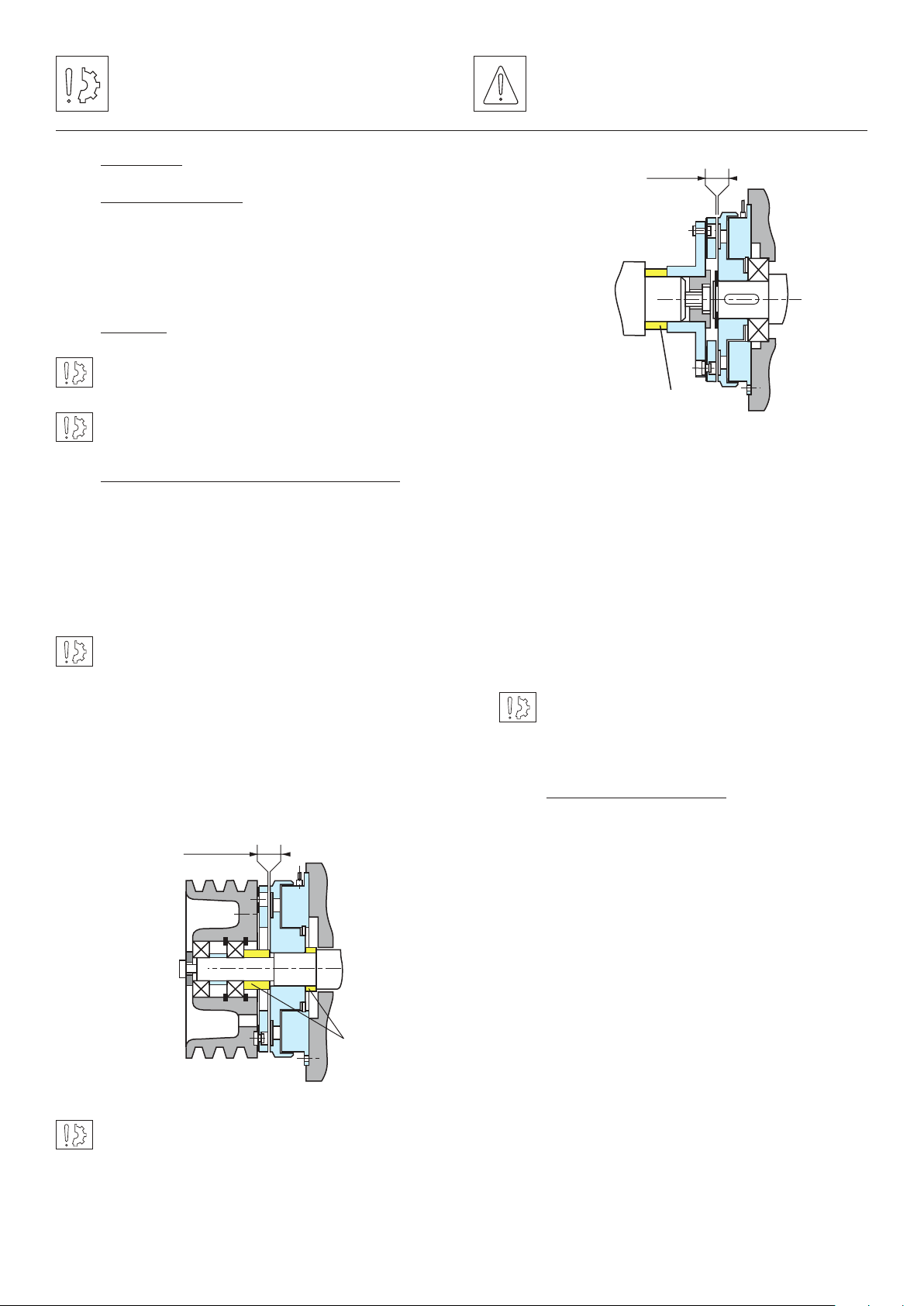
Fig. 2
Airgap
Adjusting spacer
Symbol designating an action that
might damage the apparatus
Symbol designating an action that
might be dangerous to human safety
3 Installation
3.1 Transport / storage
These units are delivered in packaging that
guarantees a 6 months storage period whether
transported by land, by air, or by sea to any
destination excepting tropical countries.
3.2 Handling
Avoid any impacts on the equipment so as not to
alter their performance.
Never carry the equipment by the electrical supply
cable.
3.3 Installation 3.3.1SFM (VAR00 and VAR01)
Inductor (104) should be fixed to the frame of the
machine, centred by the collar (see figure 1) or
directly centred on a bearing forming a support
(see figure 2). In this case, a circlip fitted in the
groove provided for the purpose holds it central to
the bearing.
In the case of collar centring, we specify an H9
tolerance.
Airgap
Adjusting spacer
Fig. 2
On VAR01 the armature is mounted on a hub
(332), sup plied reamed to tolerance H7 and
splined to tolerance P9.
The assembled hub / armature assembly
should be secured centrally so as to respecter
the nominal airgap.
It is essential when assembling to respect the
nominal airgap (see chapter 1) and dimension
M (See table 1).
The setover between the housing and shaft should
not exceed 0.05 mm.
On VAR00, the armature (331) is fixed by means
of CHC “profile head” screws (DIN 7984) locked
by means of a LOCTITE 270 type thermoplastic
liquid.
Airgap
Adjusting
spacer
Fig. 1
In the case where two co-axial shafts are fitted,
the recommended setover is 0.05 mm maximum.
The angular misalignment should not be greater
than 0,1 mm over a length of 100 mm.
When assembling or dismantling the moving
armature, never hit or pull it, this action could
generate permanent distortion of the
membrane-spring and malfunction.
3.3.2 SFM (VAR10 and VAR11)
The inductor (109) is stopped from rotating by
means of a stop foot. This should be fitted so
as to get a minimum play of 0,25 mm between
the sides of the notch to avoid any strain on the
inductor and internal bearing.
In case of vibrations, it is strongly recommended
to insert a damping elastic slot between the
anti-rotation device and the anti-rotation slot
and to fix the coil’s cable the nearest of it to
avoid whipping.
On VAR10, the armature is fixed (331) by means
of CHC “profile head” screws (DIN 7984) locked
by means of a LOCTITE 270 type thermoplastic
liquid.
Warner Electric Europe • +33 (0)2 41 21 24 24 P-2086-WE • 11/12 3
Page 4

The device supporting the moving armature
Airgap
Adjusting
spacer
Airgap
Adjusting spacer
Locking nger
Airgap
Adjusting
spacer
Airgap
Airgap
Adjusting
spacer
should be secured centrally so as to respecter
the nominal airgap.
Airgap
In the case of collar centring, we specify an H9
tolerance.
The setover between the housing and shaft
should not exceed 0,2 mm.
Airgap
Adjusting spacer
Locking nger
Fig. 3
On VAR11, the hub / moving armature assembly
(332) is supplied reamed to tolerance H7 or H8
and splined to tol erance P9.
Airgap
Adjusting spacer
Locking nger
Fig. 4
Adjusting
spacer
Fig. 5
On VAR00, the armature is fixed by means of
CHC “pro file head” screws (DIN 7984) locked
by means of a LOC TITE 270 type thermoplastic
liquid.
On VAR01 and VAR02 the armature is mounted
on a hub (332) or (333), supplied reamed to
tolerance H7 or H8 and splined to tolerance P9.
The assembled hub / armature assembly should
be secured centrally so as to respect the nominal
airgap.
The angular misalignment of the shaft should
not be greater than 0,1 mm over a length of 100
mm.
Airgap
When assembling or dismantling the moving
armature, never hit or pull it, this action
could generate permanent distortion of the
In the case where two co-axial shafts are
membrane-spring and malfunction.
fitted, the recommended setover is 0,05 mm
maximum. The angular misalignment should
not be greater than 0,1 mm over a length of
100 mm.
Adjusting spacer
It is essential when assembling to respect the
nom- inal airgap (see chapter 1).
3.3.3 PBM VAR00, VAR01 and VAR02
When assembling or dismantling the moving
Fig. 6
armature, never hit or pull it, this action could
The inductor (104) should be rigidly fixed to
the frame of the machine, centred by the collar
generate permanent distortion of the membrane
spring and malfunction.
(see figure 5) or directly centred on a bearing
forming a support (see figure 6). In this case, a
circlip fitted in the groove provided for the pur-
It is essential when assembling to respect the
nominal airgap (see chapter 1).
pose holds it central to the bearing.
4 Warner Electric Europe • +33 (0)2 41 21 24 24 P-2086-WE • 11/12
Page 5

4 Electrical connection
SFM and PBM equipment should be supplied
with Direct Current and has factory fitted wires
of length 400 mm. Polarity has no effect on
operation.
4.1 Important recommendations
Ensure that the nominal supply voltage is
complied with (a lower voltage causes a reduction
in the starting distance and transmissible torque).
The connecting wires should be of sufficient
diameter to prevent power loss between source
and the equipment to be supplied.
I (A) / L (m) 0 to 10 m from 10 to 20 m
0 to 2 (A)
3 to 6 (A)
1,5 mm
1,5 mm
2
2
1,5 mm
2,5 mm
2
2
Tolerance for the supply to the clutch or brake
terminals +5% / -10% (NF C 79-300)
4.2 Power supply
For the control of these clutches and brakes we
advise the use of Warner Electric CBC 140-4,
CBC 140-6, CBC 400, CBC 450, CBC 500, CBC
550, and CBC 700 supply units.
Warner Electric supply units provide protection
for the coils and circuits. In the case where a
brake or clutch is used without our supply units,
with switch on the DC circuit, it is essential
to protect the coil against power spikes by a
varistor fitted in parallel.
Warner Electric Europe • +33 (0)2 41 21 24 24 P-2086-WE • 11/12 5
Page 6

SFM VAR00
5 Appendices
5.1 Appendix 1
202
104
SFM VAR01
202 104
331
Rep Designation
104
202
331
Magnet
Rotor + friction material
Assembled moving armature
332
M
Rep Designation
104
202
332
Magnet
Rotor + friction material
Moving armature ext. Hub
SFM VAR10
331
Rep Designation
109
331
Magnet
Assembled moving armature
109
SFM VAR11
332
Rep Designation
109
332
Magnet
Moving armature ext. Hub
109
6 Warner Electric Europe • +33 (0)2 41 21 24 24 P-2086-WE • 11/12
Page 7

PBM VAR00
5.2 Appendix 2
331
PBM VAR01
332 104
104
Rep Designation
104
331
Magnet
Assembled moving armature
PBM VAR02
333 104
Rep Designation
104
332
Magnet
Moving armature ext. Hub
Rep Designation
104
333
Warner Electric Europe • +33 (0)2 41 21 24 24 P-2086-WE • 11/12 7
Magnet
Moving armature ext. Hub
Page 8

Warranty
Warner Electric LLC warrants that it will repair or replace (whichever it deems advisable) any product manufactured and
sold by it which proves to be defective in material or workmanship within a period of one (1) year from the date of original
purchase for consumer, commercial or industrial use.
This warranty extends only to the original purchaser and is not transferable or assignable without Warner Electric LLC’s
prior consent.
Warranty service can be obtained in the U.S.A. by returning any defective product, transportation charges prepaid, to
the appropriate Warner Electric LLC factory. Additional warranty information may be obtained by writing the Customer
Satisfaction Department, Warner Electric LLC, 449 Gardner Street, South Beloit, Illinois 61080, or by calling 815-389-
3771.
A purchase receipt or other proof of original purchase will be required before warranty service is rendered. If found
defective under the terms of this warranty, repair or replacement will be made, without charge, together with a refund for
transportation costs. If found not to be defective, you will be notified and, with your consent, the item will be repaired or
replaced and returned to you at your expense.
This warranty covers normal use and does not cover damage or defect which results from alteration, accident, neglect, or
improper installation, operation, or maintenance.
Some states do not allow limitation on how long an implied warranty lasts, so the above limitation may not apply to you.
Warner Electric LLC’s obligation under this warranty is limited to the repair or replacement of the defective product and
in no event shall Warner Electric LLC be liable for consequential, indirect, or incidental damages of any kind incurred by
reason of the manufacture, sale or use of any defective product. Warner Electric LLC neither assumes nor authorizes any
other person to give any other warranty or to assume any other obligation or liability on its behalf.
WITH RESPECT TO CONSUMER USE OF THE PRODUCT, ANY IMPLIED WARRANTIES WHICH THE CONSUMER MAY
HAVE ARE LIMITED IN DURATION TO ONE YEAR FROM THE DATE OF ORIGINAL CONSUMER PURCHASE. WITH
RESPECT TO COMMERCIAL AND INDUSTRIAL USES OF THE PRODUCT, THE FOREGOING WARRANTY IS IN LIEU
OF AND EXCLUDES ALL OTHER WARRANTIES, WHETHER EXPRESSED OR IMPLIED BY OPERATION OF LAW OR
OTHERWISE, INCLUDING, BUT NOT LIMITED TO, ANY IMPLIED WARRANTIES OF MERCHANTABILITY OR FITNESS.
Some states do not allow the exclusion or limitation of incidental or consequential damages, so the above limitation or
exclusion may not apply to you. This warranty gives you specific legal rights and you may also have other rights which
vary from state to state.
Changes in Dimensions and Specications
All dimensions and specifications shown in Warner Electric catalogs are subject to change without notice. Weights do not
include weight of boxing for shipment. Certified prints will be furnished without charge on request to Warner Electric.
Warner Electric Europe
7 rue Champfleur, B.P. 20095, St Barthelemy d’Anjou - France
+33 (0)2 41 21 24 24 • Fax: +33 (0)2 41 21 24 70
www.warnerelectric.com
Printed in USAP-2086-WE • 11/12
 Loading...