

Page 1
SFC-825, SFC-1000, SFC-1225, SFC-1525
Heavy Duty Clutch Coupling and SFC-1525
High Torque Heavy Duty Clutch Coupling
P-207
819-0516
Installation Instructions
Page 2
Contents
Installation Instructions . . . . . . . . . . . . . . . . . . . . . . . .2
SFC-825, SFC-1000, SFC-1225, SFC-1525 and
SFC-1525 Hi-Torque
Torque Tabs . . . . . . . . . . . . . . . . . . . . . . . . . . . . . . . .5
Electrical Coil Data . . . . . . . . . . . . . . . . . . . . . . . . . . .6
Burnishing and Maintenance . . . . . . . . . . . . . . . . . . . .6
Illustration Drawings
SFC-825, SFC-1000 Flange Mounted . . . . . . . . . . .8
SFC-1225, SFC-1525 and SFC-1525
Hi-Torque Flange Mounted . . . . . . . . . . . . . . . . . . .12
SFC-825, SFC-1000 Bearing Mounted . . . . . . . . .18
SFC-1225, SFC-1525 Bearing Mounted . . . . . . . .22
Bushing Part Numbers . . . . . . . . . . . . . . . . . . . . . . .28
Warranty . . . . . . . . . . . . . . . . . . . . . . . . . . .Back Cover
Follow the installation instructions
in this manual care ful ly to ensure safe, reliable
operation. All stated or implied manufacturer
warranties are voided if this product is not installed
in accordance with these in struc tions.
Failure to follow these instructions may result in product damage, equipment
damage, and serious or fatal injury to personnel.
Clutch-Coupling Spline Drive Armatures
SFC-825 SFC-1000 SFC-1225 SFC-1525
SFC-1525 Hi-Torque
The illustration drawings, parts lists, and exploded views
for these units can be found beginning on page 8.
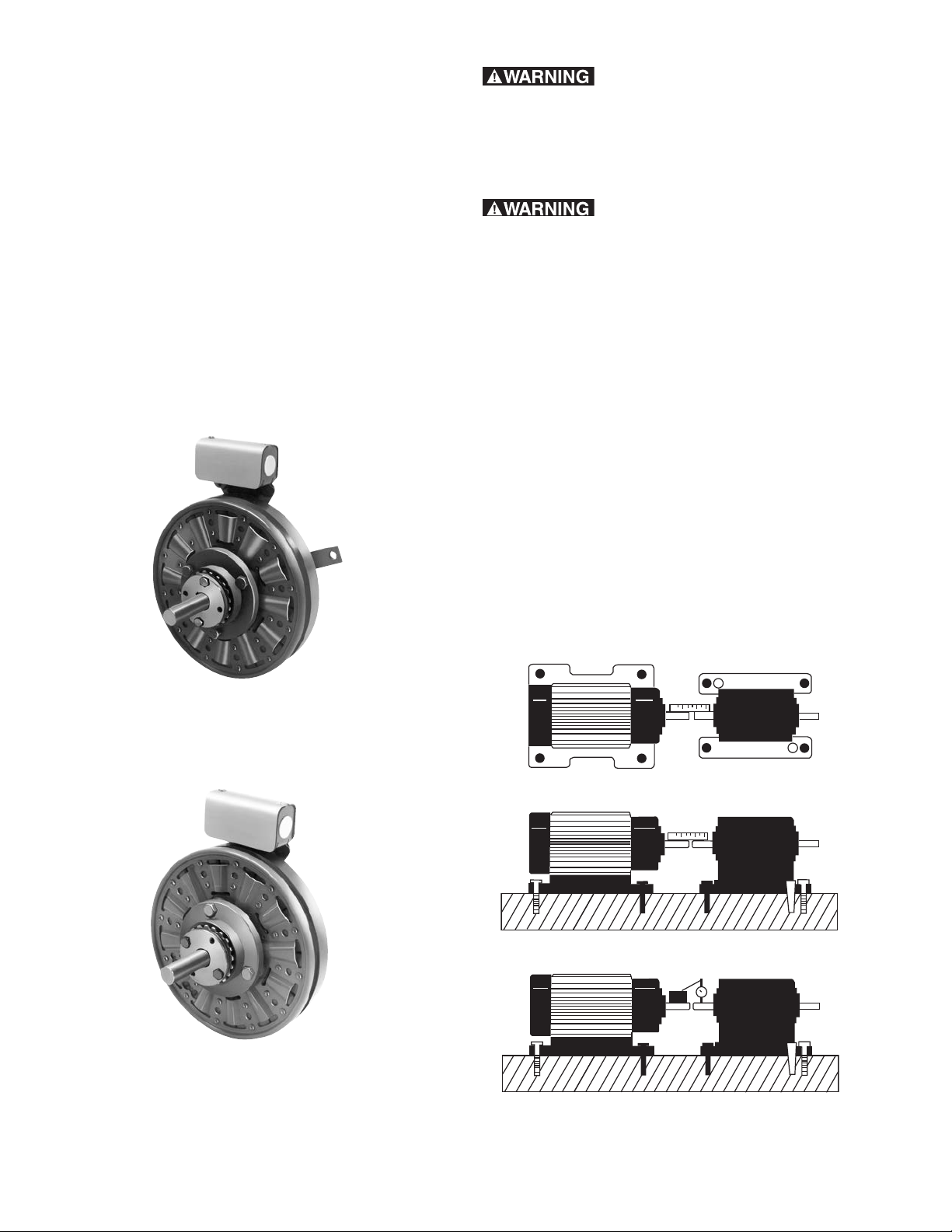
A. Aligning the Shafts
In order for the clutch-coupling unit to operate
properly, the mounting shafts of the motor and
reducer or other hardware must be aligned with
respect to each other before the unit is installed.
The two shafts should be con cen tric with each other
within .006 T.I.R., and angular alignment should be
within 1/2 degree. (See to Figure 1)
SFC-825
Bearing Mounted
SFC-825
Flange Mounted
Figure 1
Warner Electric • 800-825-9050 P-207 • 819-0516
2
Page 3

1. Use a straight-edge to check if the shafts are
Field
Pilot diameter
Mounting Surface
aligned with each other. For a more precise
indication of align ment, use a dial indicator.
2. Adjust the position of the motor, reducer, or
other hardware as required to achieve the
correct align ment.
3. To be sure the shafts stay in alignment, drill
holes for tapered dowel pins through the
mounting bases of the motor, reducer, or
other hardware and into the mounting
surfaces. This procedure will ensure that,
after the clutch-coupling has been installed,
the shafts can easily be placed in proper
alignment again by lining up the holes and
secured by inserting the dow el pins.
B. Installing the Conduit Box
Install the conduit box on the field. Instructions for
this procedure can be found with conduit box.
Installation Manual P-1393 • 819-0200.
C. Mounting the Field-and-Rotor
Assembly
c. The field assembly is then fastened in place
with capscrews and lockwashers. (Figure 3)
Figure 3
d. After the unit is in place the mounting face
and pilot di am e ter must be square and
concentric with the shaft in accordance with
the tolerances listed on the draw ings.
(Fig ure 4)
Flange-Mounted Units
The fields and rotors are shipped separately for
flange-mounted units. On some applications it will
be nec es sary to mount the rotor first, and then
bring the field into position. In other instances, the
field will be mounted first, and then the rotor
(mounted on a shaft) will be inserted into place.
1. Mounting the Field
a. Care must be taken in selecting the
location for mount ing the field assembly.
Pilot diameters are machined on the field
mounting flange to aid in hold ing the field
in the proper position.
b. An appropriate pilot diameter must be
provided on the mounting surface as
well. (Figure 2)
Figure 4
2. Mounting the Rotor
a. Assemble the rotor to the rotor hub with
capscrews and lockwashers. The rotor is
reversible de pend ing on the side from which
the taperlock bushing must en ter. A pilot
di am e ter is machined on the rotor hub to
assure a proper fit.
b. The rotor hub is mounted on the shaft with
a taper lock bushing. Be sure all parts are
clean and free of dirt, chips, and burrs
before assembling.
c. Insert the bushing into the taper bore.
Warner Electric • 800-825-9050 P-207 • 819-0516
Figure 2
d. Loosely assemble the two locking screws
be tween the bushing and rotor.
e. Insert the key into the shaft keyway. Prick
punch the end of the keyway to ensure that
the key can not slide out.
3
Page 4
f. Slide the rotor assembly over the key and
onto the shaft.
g. Place the edge of the rotor 1/16" - 1/8"
before the line that is inscribed into the O.D.
of the field.
h. Lock the rotor into place by alternately
tightening the two locking screws in the
bushing. As the screws are tight ened, the
rotor normally is pulled 1/16" - 1/8" further
onto the bushing (towards the field).
When the rotor is secured tightly on the
bush ing, the edge of the rotor must be
ap prox i mate ly even with the line
inscribed in the field. The over all axial
di men sion from the face of the rotor to the
back of the field flange is shown on the
illustration draw ings. Squareness and
con cen tric i ty tol er anc es must also be held
as specified on the draw ings to assure that
the unit functions correctly.
Bearing Mounted Units
In bearing-mounted units, the field and rotor are shipped
as an assembly. Either this assembly or the armature and
hub assembly can be mounted on the shaft first,
de pend ing on the characteristics of each application.
D. Assembling the Armature and Hub
These units contain a spline drive armature and hub.
The armatures are shipped with a built-in autogap spring
ac ces so ry. This device automatically maintains a gap of
about 1/32" between the armature and rotor faces for
the life of the units.
These units are shipped with the armature, splined
ar ma ture adapter, and autogap already assembled. The
splined hub, retainer ring, and bushing are shipped as
separate parts.
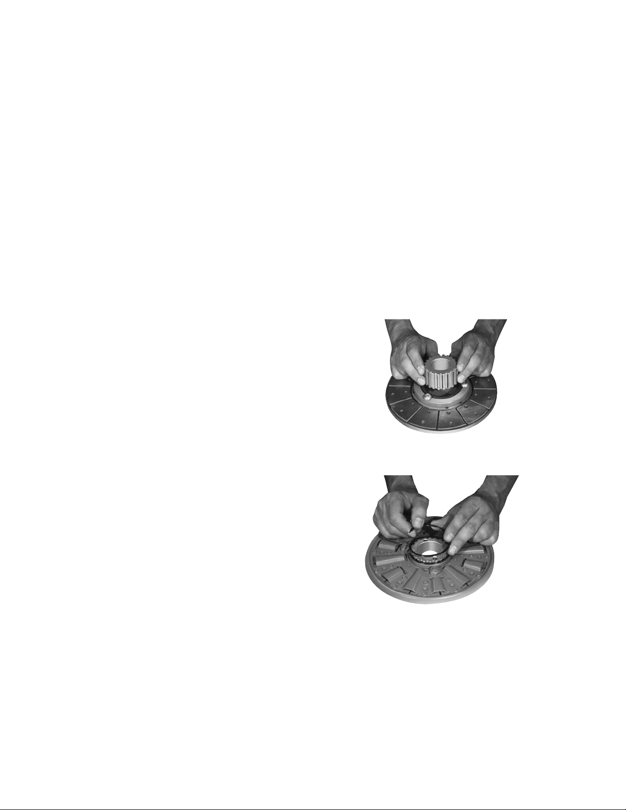
Follow these instructions to assemble the splined
ar ma ture assembly and hub:
1. Place the armature assembly on a flat surface with
the segmented side up.
2. Push the splined hub, with the retainer ring groove
down, through the autogap spring and splined
armature adapt er (Figure 5). (Considerable force is
required to start the hub through the armature.)
1. Field and rotor assemblies are mounted on the shaft
a taperlock bushing. Insert the bushing into the
tapered bore.
2. Loosely assemble the two locking screws between
the taperlock bushing and the rotor.
3. Insert the key into the shaft keyway. Prick punch the
end of the keyway to ensure that the key cannot
slide out.
4. Slide the rotor assembly onto the shaft over the key.
5. If the armature has been secured to the shaft first,
ad just the rotor's position to allow a 1/32-inch gap
be tween the two faces. (See Figure 8.)
6. Lock the assembly into place by alternately
tight en ing the two locking screws.
7. A tab or torque arm on the field is used to prevent
ro ta tion of the field caused by normal bearing drag.
In sert ei ther a pin in the U-slot or a fork around the
torque arm to prevent this rotation. Under no
cir cum stanc es, however, should the field be so
tightly re strained as to preload the bearing. (For
more in for ma tion on torque tabs, see page 5.)
Figure 5
3. Turn the armature assembly over, and insert the
Figure 6
retainer ring in the groove. (Figure 6)
4. Slide the armature assembly up against the retainer
ring.
Warner Electric • 800-825-9050 P-207 • 819-0516
4
Page 5
E. Mounting the Armature-Hub Assembly
1/32-inch Gap
Armature
Rotor
Torque Tabs
1. Insert the bushing into the retainer ring side of the
splined hub. The clearance holes in the bushing
flange should line up with the tapped holes in the
splined hub. (Figure 7)
Figure 7
2. Slide the complete assembly on the shaft and place
it in contact with the rotor.
3. Tighten the bushing capscrews, taking a few turns
at a time on each capscrew. As the capscrews are
tight ened, the armature will back away slightly from
the rotor. There should be a clearance of 1/16"
be tween the ar ma ture and rotor when the
capscrews are com plete ly tight.
Clutches
Many Warner Electric clutch assemblies have a bearing
mounted stationery field. By design the bearing
main tains its proper position between the field and rotor
mak ing it easy for the customer to mount the field-rotor
as sem bly. However, the bearing has a slight drag which
tends to make the field rotate with the rotor if not
re strained. And, since the field has lead wires attached,
it must be restrained to prevent rotation and pulling of
these wires. To counteract this rotational force, the field
has a “torque tab” to which the customer must attach
an ap pro pri ate anti-rotational restraint.
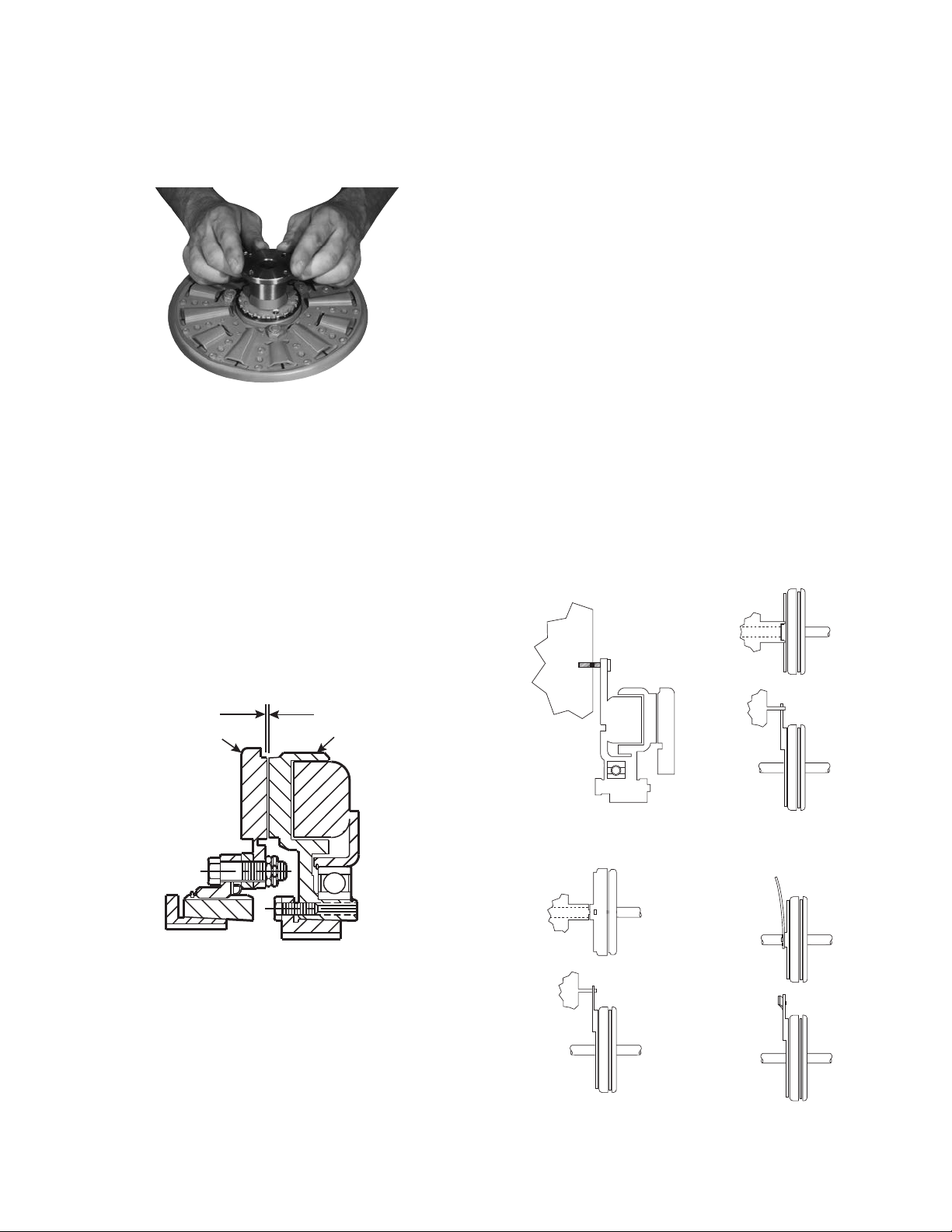
A few hints regarding proper torque tab restraints are in
order. First and foremost, it is important to recognize that
the force to be overcome is very small and the tab
should not be restrained any manner which will preload
the bearing. For example, if the clutch is mounted with
the back of the field adjacent to a rigid machine member
the customer should not attach a capscrew tightly
between the tab and the machine member. This may
pull the tab back against the rigid member as shown in
Figure 1 and preload the bearing. The recommended
methods are il lus trat ed in Illustrations 2, 3, and 4. The
method selected is primarily a matter of customer
preference or con ve nience.
4. When the assembly has been secured on the shaft,
push the armature against the rotor face. When the
ar ma ture is released, it will spring back about 1/32".
(Fig ure 8)
Figure 8
Once this gap is set, it will be automatically maintained
for the life of the unit.
Illustration 1
Rigid Member
Illustration 2
Rigid Member
Straddling Tab
Illustration 3
Pin In Hole Loosely
Warner Electric • 800-825-9050 P-207 • 819-0516
Illustration 4
Flexible Strap
5
Page 6

Electrical Coil Data
Unit Size SF-825 SF-825 Brg. SF-1000
Voltage–DC 6 24 90 6 24 90 6 24 90
Resistance @ 20°C–Ohms 1.23 20.9 267.0 1.098 14.6 221 1.07 14.4 214.4
Current–Amperes 4.9 1.15 .34 5.464 1.65 .407 5.61 1.67 .42
Watts 29 28 30 33 40 37 34 40 38
Coil Build-Up–Milliseconds 222 200 245 180 200 225 256 275 283
Coil decay–Milliseconds 105 120 100 115 120 130 123 105 90
Unit Size SF-1225 SF-1525 SF-1525 HT
Voltage – DC 6 24 90 6 24 90 6 24 90
Resistance @ 20°C–Ohms 1.21 19.5 268.3 1.11 15.5 239.1 .55 7.63 113.4
Current – Amperes 4.97 1.23 .34 5.41 1.55 .38 10.83 3.14 .794
Watts 30 30 30 32 37 34 65 75 72
Coil Build-Up – Milliseconds 475 440 510 505 535 575 480 535 560
Coil decay–Milliseconds 240 230 220 230 237 215 210 183 160
Notes: Build-up time equals current to approx.* 90% of steady state value and flux to 90%
Decay time equals current to approx.* 10% of steady state value and flux to 10%.
*Approx. because current leads or lags flux by a small amount.
Burnishing and Maintenance
Burnishing
Intimate metal to metal contact is essential between the
armature and the metal rings (poles) of the magnet or
rotor. Warner Electric clutches and brakes leave the
fac to ry with the friction material slightly undercut to
assure good initial contact.
Normally, the desired wearing-in process occurs nat u ral ly
as the surfaces slip upon engagement. The time for
wear-in, which is necessary to obtain the ultimate torque
of the unit, will vary depending on speed, load, or cycle
duty.
If maximum torque is required immediately after
in stal la tion, the unit should be burnished by slipping
the friction surfaces together at reduced voltage. It is
rec om mend ed that the burnishing be done right on
the application, if at all possible.
Burnishing at high speed will result in a smoother wear-in
pattern and reduce the time for burnishing. The volt age
should be set at approximately 30% or 40% of the rated
value.
The unit should be cycled on and off to allow sufficient
time between slip cycles to prevent overheating.
When a Warner Electric brake or clutch is properly
as sem bled and installed, no further servicing, lubrication,
or maintenance should be required throughout the life of
the unit.
Maintenance
Wear Pattern: Wear grooves appear on the armature
and rotor surfaces. This is a normal wear condition, and
does not impair functioning of the unit. Normally, the
rotor and armature, as a mating pair, will wear at the
same rate. It is the usual recommendation that both
components be replaced at the same time.
Remachining the face of a worn armature is not
rec om mend ed. If a replacement armature is to be used
with a used rotor, it is necessary to remachine the worn
rotorface. In refacing a rotor: (1) machine only enough
material to clean up the complete face of the magnet; (2)
hold the face within .005'' of parallel with the mounting
plate; and (3) undercut the molded facing material
.002''-.004'' below the metal poles.
Heat: Excessive heat and high operating temperatures
are causes of rapid wear. Units therefore, should be
ven ti lat ed as efficiently as possible, especially if the
ap pli ca tion requires fast, repetitive cycle operation.
Foreign Materials: If units are used on machinery
where fine, abrasive dust, chips or grit are dispelled into
the at mo sphere, shielding of the brake or clutch may be
nec es sary if maximum life is to be obtained.
Warner Electric • 800-825-9050 P-207 • 819-0516
6
Page 7

Where units are used near gear boxes or transmissions
requiring frequent lubrication, means should be pro vid ed
to protect the friction surfaces from oil and grease to
pre vent serious loss of torque.
Oil and grease accidentally reaching the friction surfaces
may be removed by wiping with a rag dampened with a
suitable cleaner, which leaves no residue. In performing
this operation, do not drench the friction material.
If the friction materials have been saturated with oil or
grease, no amount of cleaning will be completely
ef fec tive. Once such a unit has been placed back in
service, heat will cause the oil to boil to the surface,
resulting in further torque loss.
Torque Loss: If a brake or clutch slips or loses torque
completely, the initial check should be the input voltage
to the field as follows:
90-Volt Series: Connect a DC voltmeter with a range of
0-100 or more directly across the field terminals. With
the power on and the potentiometer turned up, a normal
reading is 90 volts, although 85 to 95 is satisfactory. The
reading should drop as the potentiometer control is
ad just ed counterclockwise.
24-Volt Series: Use a DC voltmeter with a range of 0-30
volts or more. A normal reading is approximately 22-26
volts.
Use a DC voltmeter of approximately 0-15 volt range.
A normal reading is from 5.5 to 6.5 volts.
The above checks normally are sufficient. Further
checks may be made as follows: a low range ammeter,
when connected in series with one field lead, will
normally in di cate approximately .40 amperes for the 90
volt units, 1.0 ampere for the 24 volt, and 3.5 amperes
for the 6 volt series. These readings are with the power
on and the potentiometer control in the maximum
position.
Ohmmeter checks should be made with the power off
and the circuit open (to be certain, disconnect one lead
to the field). Average resistance for the 90 volt series is
220 ohms; for the 24 volt, 20 ohms; and for the 6 volt
series, 1.5 ohms. A very high or infinite resistance
read ing would indicate an open coil.
If the above checks indicate that the proper voltage and
current is being supplied to the magnet, mechanical
parts should be checked to assure that they are in good
op er at ing condition and properly installed.
Warner Electric • 800-825-9050 P-207 • 819-0516
7
Page 8
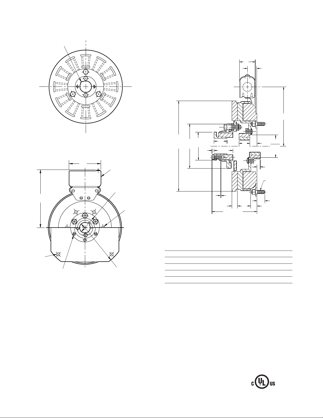
SFC-825 Clutch Coupling Flange Mounted Drawing I-25564
See page 28 for details
on Bushings.
1.546
.921
5.656
Armature View
3.750 Max.
Removable plug in ends for
1/2" conduit.
3.503/3.501
6.812
.358/.338 dia.
(4) holes
equally spaced
on 8.875 dia. *
.350/.341 dia. (6) holes equally
spaced on 2.875 dia. **
Pilot Dia.
.358/.338 dia.
(6) holes
equally
spaced on
4.250 dia. *
9.749/9.747
Pilot Dia.
Field View
(Inside & Outside Mounted)
Customer Shall Maintain:
1. Concentricity of field mounting pilot diameter with
rotor mounting shaft within .006 T.I.R.
2. Squareness of field mounting face with rotor shaft
within .006 T.I.R. mea sured at field
mounting bolt circle.
8.656
Max.
Dia.
* Mounting holes are within .010 of true po si tion relative to pilot
diameter.
** Mounting holes are within .008 of true po si tion relative to pilot
diameter.
4.250
Dia.
2.500
Dia.
.156
1.250
1.765
.531
1.00
.062
1.312
4.406 Max.
.687
.281
5/16-18
UNC-3A
.602/.586
2.253
2.251
Pilot
Dia.
.562 Max.
Arm Shaft .500 – 1.500
Rotor Shaft .500 – 1.250
Static Torque 125 lb. ft.
Maximum Speed 4,000 rpm
Standard Voltage D.C. 6, 24, 90
All dimensions are nominal unless otherwise noted.
Note: The two mating shafts on which the clutch is
mounted must be mounted rigidly to prevent
flexing during engagement. Any flexing will cause
vibration and rapid clutchwear. The drive motor
should not be mounted on the reducer "scoop"
mount or other flexible mounts.
3. Rotor mounting shaft concentric with ar ma ture
mounting shaft within .006 T.I.R.
4. Angular alignment of shafts wtihin 1/2 degree.
Warner Electric • 800-825-9050 P-207 • 819-0516
8
Page 9

1
2
3
4-1
4-2
4-3
4
(Shipped Assembled)
4-4
4-6
4-5
9A
10A
11
9B
8
7
6
5
10B
11
SFC-825 Clutch Coupling Flange Mounted Inside Mtd. Outside Mtd.
SFC-825, F.M.
Item Description Part Number Qty.
1 Bushing*
1/2" to 1-1/2" Bore 180-0002 to 180-0018 1
2 Retainer Ring 748-0006 1
3 Splined Hub 540-0057 1
4 Armature & Splined Adapter 5201-111-001 1
4-1 Capscrew 797-0341 3
4-2 Splined Adapter 104-0008 1
4-3 Autogap Accessory 5321-101-006 1
4-4 Spacer 748-0333 3
4-5 Armature 5321-111-022 1
4-6 Locknut 661-0004 3
5 Mounting Accessory 5201-101-007 1
6 Rotor 1
Standard Friction Material 5201-751-003
Optional LK Facing 5201-751-007
7 Bushing*
8 Rotor Hub 540-0013 1
9A Field - Inside Mounted 1
9B Field - Outside Mounted 1
1/2" to 1-1/4" Bore 180-0101 to 180-0013 1
6 Volt 5201-451-006
24 Volt 5201-451-008
90 Volt 5201-451-010
6 Volt 5201-451-014
24 Volt 5201-451-016
90 Volt 5201-451-018
SFC-825, F.M.
Item Description Part Number Qty.
10A Mounting Accessory - I.M. 5321-101-001 1
10B Mounting Accessory - O.M. 5321-101-002 1
11 Conduit Box 5200-101-012 1
*See page 28 for specific part numbers.
How to Order:
1. Specify Bore Size for Item 1.
2. Specify Bore Size for Item 7.
3. Specify Voltage for Item 9A or 9B.
4. Specify Inside Mounted for Items 9A and 10A or
Outside Mounted for Items 9B and 10B.
Example:
SFC-825 Clutch Coupling per I-25564 - 90 Volt, Inside
Mounted, 1" Bore (Item 1), 1" Bore (Item 7)
These units, when used in conjunction with the correct
Warner Electric conduit box, meet standards of UL508
and are listed under guide card #NMTR, file #59164.
Warner Electric • 800-825-9050 P-207 • 819-0516
9
Page 10
SFC-1000 Clutch Coupling Flange Mounted Drawing I-25584
3.750
7.687 MAX
Removeable plug in ends
for 1/2” conduit
.358/.388 dia. (6) holes equally
spaced on a6.125 dia. *
.350/.341 dia. (6) holes
equally spaced on 4.875 dia.**
5.378/5.376
Pilot Dia.
11.500/11.498
Pilot Dia.
.358/.338 dia *(8) holes equally
spaced on 10.625 dia.*
1.560
Ø4.127 ±.001
1.250
.250
.562 MAX
.093
.562
1.375
5/16-18 UNC-3A
6.531
Ø10.328 MAX
HOLE FOR 1/2" CONDUIT
(EACH END)
.500
.910 MAX
5.359 MAX
.062
.234
2.500
2.688
Ø4.094
Ø6.000
PILOT
See page 28 for details
on Bushings.
Armature View
Field View
(Inside & Outside Mounted)
Customer Shall Maintain:
1. Concentricity of field mounting pilot diameter with
rotor mounting shaft within .006 T.I.R.
2. Squareness of field mounting face with rotor shaft
within .006 T.I.R. mea sured at field mounting bolt
circle.
3. Rotor mounting shaft concentric with ar ma ture
mounting shaft within .006 T.I.R.
4. Angular alignment of shafts within 1/2 degree.
* Mounting holes are within .010 of true po si tion relative to pilot
diameter.
** Mounting holes are within .008 of true po si tion relative to pilot
diameter.
Arm Shaft .750 – 2.687
Rotor Shaft .500 – 2.000
Static Torque 240 lb. ft.
Maximum Speed 3,600 rpm
Standard Voltage D.C. 6, 24, 90
All dimensions are nominal unless otherwise noted.
Note: The two mating shafts on which the clutch is
mounted must be mounted rigidly to prevent
flexing during engagement. Any flexing will cause
vibration and rapid clutchwear. The drive motor
should not be mounted on the reducer "scoop"
mount or other flexible mounts.
Warner Electric • 800-825-9050 P-207 • 819-0516
10
Page 11

SFC-1000 Clutch Coupling Flange Mounted Inside Mtd. Outside Mtd.
1
2
3
4-1
4-2
4-3
4
(Shipped Assembled)
4-4
4-6
4-5
9A
10A
11
9B
8
7
6
5
10B
11
SFC-1000, F.M.
Item Description Part Number Qty.
1 Bushing*
3/4" to 2-11/16" Bore 180-0026 to 180-0057 1
2 Retainer Ring 748-0007 1
3 Splined Hub 540-0062 1
4 Armature & Splined Adapter 5202-111-001 1
4-1 Capscrew 797-0341 3
4-2 Splined Adapter 104-0009 1
4-3 Autogap Accessory 5322-101-004 1
4-4 Spacer 748-0333 3
4-5 Armature 5322-111-036 1
4-6 Locknut 661-0004 3
5 Mounting Accessory 5201-101-007 1
6 Rotor 1
Standard Friction Material 5202-751-003
Optional LK Facing 5202-751-007
7 Bushing*
1/2" to 2" Bore 180-0155 to 180-0179 1
8 Rotor Hub 540-0315 1
9A Field - Inside Mounted 1
9B Field - Outside Mounted 1
6 Volt 5202-451-004
24 Volt 5202-451-006
90 Volt 5202-451-007
6 Volt 5202-451-011
24 Volt 5202-451-013
90 Volt 5202-451-014
SFC-1000, F.M.
Item Description Part Number Qty.
10A Mounting Accessory - I.M. 5321-101-001 1
10B Mounting Accessory - O.M. 5321-101-002 2
11 Conduit Box 5200-101-012 1
*See page 28 for specific part numbers.
How to Order:
1. Specify Bore Size for Item 1.
2. Specify Bore Size for Item 7.
3. Specify Voltage for Item 9A or 9B.
4. Specify Inside Mounted for Items 9A and 10A or
Outside Mounted for Items 9B and 10B.
Example:
SFC-1000 Clutch Coupling per I-25584 - 90 Volt, Inside
Mount ed, 1-1/4" Bore (Item 1), 1-1/2" Bore (Item 7)
These units, when used in conjunction with the correct
Warner Electric conduit box, meet standards of UL508
and are listed under guide card #NMTR, file #59164.
Warner Electric • 800-825-9050 P-207 • 819-0516
11
Page 12

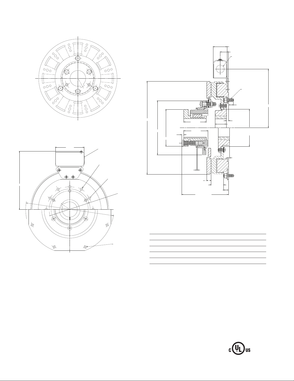
SFC-1225 Clutch Coupling Flange Mounted Drawing I-25604
See page 28 for de tails
on Bush ings.
1.546
.921
7.531
Armature View
3.750
8.687 Max.
Removable plug in ends
for 1/2" conduit.
.358/.338 dia. (6) holes equally
spaced on 7.250 dia.*
6.378/6.376
Pilot Dia.
.350/.341 dia. (8)
holes equally
spaced on 6.062
dia.**
13.875/13.871
Pilot Dia.
.358/.338 dia. (8) holes equally
spaced on 13.000 dia.*
Field View
(Inside & Outside Mounted)
Customer Shall Maintain:
1. Concentricity of field mounting pilot diameter with
rotor mounting shaft within .006 T.I.R.
2. Squareness of field mounting face with rotor
mounting shaft within .006 T.I.R. measured at field
mounting bolt circle.
12.703
Max.
12.625
Dia.
Dia.
* Mounting holes are within .010 of true position relative to pilot
diameter.
** Mounting holes are within .008 of true position relative to pilot
diameter.
7.062
Dia.
.234
4.093
Dia.
.062
2.500
2.687
.562
5.890 Max.
1.750
1.562
.562
.312
5.438
5.436
.281
5/16-18
UNC-3A
.758
.742
Pilot
Dia.
Arm Shaft .750 – 2.687
Rotor Shaft .500 – 2.500
Static Torque 465 lb. ft.
Maximum Speed 3,000 rpm
Standard Voltage D.C. 6, 24, 90
All dimensions are nominal unless otherwise noted.
3. mounting shaft concentric with armature mounting
shaft within .006 T.I.R.
4. Angular alignment of shafts within 1/2 degree.
When Hub is Furnished by Customer:
Rotor mounting pilot diameter must be concentric with
rotor mounting shaft within .006 T.I.R.
Warner Electric • 800-825-9050 P-207 • 819-0516
12
Page 13

1
2
3
4-2
4-3
4
(Shipped Assembled)
4-4
4-1
4-5
4-6
9A
10A
7
6
5
8
10B
9B
11
11
SFC-1225 Clutch Coupling Flange Mounted Inside Mtd. Outside Mtd.
SFC-1225
Item Description Part Number Qty.
1 Bushing*
3/4" to 2-11/16" Bore 180-0026 to 180-0057 1
2 Retainer Ring 748-0005 1
3 Splined Hub 540-0064 1
4 Armature & Splined Adapter 5203-111-001 1
4-1 Locknut 661-0005 4
4-2 Splined Adapter 104-0010 1
4-3 Autogap Accessory 5323-101-002 1
4-4 Spacer 266-0004 4
4-5 Armature 5323-111-034 1
4-6 Screw 797-0356 4
5 Mounting Accessory 5321-101-002 2
6 Rotor 1
Standard Friction Material 5203-751-001
Optional LK Facing 5203-751-004
7 Bushing*
1/2" to 2-1/2" Bore 180-0185 to 180-0217 1
8 Rotor Hub 540-0318 1
9A Field - Inside Mounted 1
6 Volt 5203-451-002
24 Volt 5203-451-006
90 Volt 5203-451-005
9B Field - Outside Mounted 1
6 Volt 5203-451-010
24 Volt 5203-451-013
90 Volt 5203-451-011
SFC-1225
Item Description Part Number Qty.
10A Mounting Accessory - I.M. 5321-101-001 1
10B Mounting Accessory - O.M. 5321-101-002 2
11 Conduit Box 5200-101-012 1
*See page 28 for specific part numbers.
How to Order:
1. Specify Bore Size for Item 1.
2. Specify Bore Size for Item 7.
3. Specify Voltage for Item 9A or 9B.
4. Specify Inside or Outside Mounted for Item 5.
5. Specify Inside Mounted for Items 9A and 10A or
Outside Mounted for Items 9B and 10B.
Example:
SFC-1225 Clutch Coupling per
I-25604 - 90 Volt, Inside Mounted,
1-1/2" Bore (Item 1), 1-3/4" Bore (Item 7).
These units, when used in conjunction with the correct
Warner Electric conduit box, meet the standards of
UL508 and are listed under guide card #NMTR, file
#59164.
Warner Electric • 800-825-9050 P-207 • 819-0516
13
Page 14

SFC-1525 Clutch Coupling Flange Mounted Drawing I-25630
See page 28 for de tails
on Bush ings.
1.546
.921
9.187
Armature View
3.750
10.343 Max.
Removable plug in ends for
1/2" conduit.
.358/.338 dia. (12) holes
equally spaced on 9.750
dia.*
9.002/9.000
Pilot Dia.
.350/.341 dia. (8)
holes equally
spaced on 8.500
16.875/16.871
Pilot Dia.
.358/.338 dia. (12) holes
equally spaced on 16.000
dia.*
Field View
(Inside & Outside Mounted)
Customer Shall Maintain:
1. Concentricity of field mounting pilot diameter with
rotor mounting shaft within .006 T.I.R.
dia.**
15.671
Max.
15.578
Dia.
Dia.
* Mounting holes are within .010 of true position relative to pilot
diameter.
** Mounting holes are within .008 of true position relative to pilot
diameter.
8.750
Dia.
.234
4.093
Dia.
.062
2.500
2.687
.562
6.031 Max.
2
1.562
.562
.218
7.878
7.876
Pilot
Dia.
.437
5/16-18
UNC-3A
.758
.742
Arm Shaft .750 – 2.687
Rotor Shaft .937 – 3.000
Static Torque 700 lb. ft.
Maximum Speed 2,000 rpm
Standard Voltage D.C. 6, 24, 90
All dimensions are nominal unless otherwise noted.
2. Squareness of field mounting face with rotor
mounting shaft within .006 T.I.R. measured at field
mounting bolt circle.
3. Rotor mounting shaft concentric with armature
mounting shaft within .006 T.I.R.
4. Angular alignment of shafts within 1/2 degree.
When Hub is Furnished by Customer:
Rotor mounting pilot diameter must be concentric with
rotor mounting shaft within .006 T.I.R.
Warner Electric • 800-825-9050 P-207 • 819-0516
14
Page 15

SFC-1525 Clutch Coupling Flange Mounted Inside Mtd. Outside Mtd.
9A
10A
7
6
5
8
10B
9B
11
11
1
2
3
4-1
4-2
4-3
4
(Shipped Assembled)
4-4
4-5
4-6
4-7
SFC-1525
Item Description Part Number Qty.
1 Bushing*
3/4" to 2-11/16" Bore 180-0026 to180-0057* 1
2 Retainer Ring 748-0005 1
3 Splined Hub 540-0064 1
4 Armature & Splined Adapter 5204-111-004 1
4-1 Capscrew 797-0342 8
4-2 Splined Adapter 104-0011 1
4-3 Autogap Accessory 5323-101-002 1
4-4 Retainer Plate 686-0003 1
4-5 Spacer 748-0333 8
4-6 Armature 5324-111-034 1
4-7 Locknut 661-0004 8
5 Mounting Accessory 5321-101-002 2
6 Rotor 1
Standard Friction Material 5204-751-002
Optional LK Facing 5204-751-004
7 Bushing*
15/16" to 3" Bore 180-0223 to 180-0256 1
8 Rotor Hub 540-0004 1
9A Field - Inside Mounted 1
6 Volt 5204-451-013
24 Volt 5204-451-015
90 Volt 5204-451-016
9B Field - Outside Mounted 1
6 Volt 5204-451-055
24 Volt 5204-451-056
90 Volt 5204-451-057
SFC-1525
Item Description Part Number Qty.
10A Mounting Accessory - I.M. 5321-101-001 2
10B Mounting Accessory - O.M. 5321-101-001 2
11 Conduit Box 5200-101-012 1
*See page 28 for specific part numbers.
How to Order:
1. Specify Bore Size for Item 1.
2. Specify Bore Size for Item 7.
3. Specify Voltage for Item 9A or 9B.
4. Specify Inside Mounted for Items 9A and 10A or
Outside Mounted for Items 9B and 10B.
Example:
SFC-1525 Clutch Coupling per
I-25630 - 90 Volt, Inside Mounted,
1-1/2" Bore (Item 1), 1-3/4" Bore (Item 7).
These units, when used in conjunction with the correct
Warner Electric conduit box, meet the standards of
UL508 and are listed under guide card #NMTR, file
#59164.
Warner Electric • 800-825-9050 P-207 • 819-0516
15
Page 16

SFC-1525 H.T. Clutch Coupling, Hi-Torque Flange Mounted Drawing I-25631
1.546
.921
9.187
.562
Max.
.218
7.878
7.876
Pilot
Dia.
5/16-18
UNC-3A
.758/.742
10.343
See page 28 for details
Armature View
3.750
Removable plug in ends for
1/2" conduit.
See page 28 for details on Bushings.
equally spaced on 8.500 dia.**
on Bushing.
.350/.341 dia. (8) holes
9.002/9.000
Pilot Dia.
.358/.338 dia. (12)
holes equally spaced
on 9.750 dia.
15.781
Max.
15.578
Dia.
Dia.
4.093
2.500
Dia.
8.750
Dia.
.234
* Mounting holes are within .010 of true position relative to pilot
diameter.
** Mounting holes are within .008 of true position relative to pilot
diameter.
2.687
.062
.562
6.031 Max.
2
.437
1.562
5/16-18 UNC-2B (2) holes
equally spaced for removal
of rotor from hub.
Field View
Arm Shaft .750 – 2.687
Rotor Shaft .937 – 3.000
Static Torque 1,350 lb. ft.
Maximum Speed 2,000 rpm
Standard Voltage D.C. 6, 90
Customer Shall Maintain:
All dimensions are nominal unless otherwise noted.
1. Concentricity of field mounting pilot diameter with
rotor mounting shaft within .006 T.I.R.
2. Squareness of field mounting face with rotor
mounting shaft within .006 T.I.R. measured at
field mounting bolt circle.
3. Rotor mounting shaft concentric with armature
mounting shaft within .006 T.I.R.
4. Angular alignment of shafts within 1/2 degree.
When Hub is Furnished by Customer:
Rotor mounting pilot diameter must be concentric with
rotor mounting shaft within .006 T.I.R.
Warner Electric • 800-825-9050 P-207 • 819-0516
16
Page 17

SFC-1525 H.T. Clutch Coupling, Hi-Torque Flange Mounted Inside Mtd.
11
9
10
8
7
6
5
1
2
3
4-1
4-2
4-3
4
(Shipped Assembled)
4-4
4-5
4-6
4-7
SFC-1525, H.T.
Item Description Part Number Qty.
1 Bushing*
3/4" to 2-11/16" Bore 180-0026 to 180-0057 1
2 Retainer Ring 748-0005 1
3 Splined Hub 540-0064 1
4 Armature & Splined Adapter 5204-111-004 1
4-1 Capscrew 797-0342 8
4-2 Splined Adapter 104-0011 1
4-3 Autogap Accessory 5323-101-002 1
4-4 Retainer Plate 686-0003 1
4-5 Spacer 748-0333 8
4-6 Armature 5324-111-034 1
4-7 Locknut 661-0004 8
5 Mounting Accessory 5321-101-002 2
6 Rotor 5204-751-001 1
7 Bushing*
15/16" to 3" Bore 180-0223 to 180-0256 1
8 Rotor Hub 540-0004 1
9 Field - Inside Mounted 1
6 Volt 5204-451-005
24 Volt 5204-451-066
90 Volt 5204-451-006
10 Mounting Accessory - I.M. 5321-101-001 2
11 Conduit Box 5200-101-012 1
*See page 28 for specific part numbers.
How to Order:
1. Specify Bore Size for Item 1.
2. Specify Bore Size for Item 7.
Example:
SFC-1525 Clutch Coupling, Hi-Torque,
per I-25631 - 90 Volt
2" Bore (Item 1), 2-1/2" Bore (Item 7)
These units, when used in conjunction with the correct
Warner Electric conduit box, meet the standards of
UL508 and are listed under guide card #NMTR, file
#59164.
Warner Electric • 800-825-9050 P-207 • 819-0516
17
Page 18

SFC-825 Clutch Coupling Bearing Mounted Drawing I-25574
See page 28 for details on
Bushings.
1.546
.984
5.656
.343
.350/.342
Armature View
3.750
45°
.875
5.000
Field View
Removable plug in ends
for 1/2" conduit.
6.812
See page 28 for details
on Bushings.
4.250
Dia.
1.250
2.500
Dia.
.156
1.765
.062
.562
4.468 Max.
4.562 Max.
1.250
1.296
.187
1.656
Reverse
Mounting
Arm Shaft .500 – 1.500
Rotor Shaft .500 – 1.500
Static Torque 150 lb. ft.
Maximum Speed 3,600 rpm
Standard Voltage D.C. 6, 24, 90
All dimensions are nominal unless otherwise noted.
8.656
Max.
Dia.
Customer Shall Maintain:
1. Armature mounting shaft concentric with field and
rotor mounting shaft within .006 T.I.R.
2. Angular alignment of shafts within 1/2 degree.
Warner Electric • 800-825-9050 P-207 • 819-0516
18
Page 19

1
3
2
4-1
4-2
4-3
4
(Shipped Assembled)
4-4
4-6
4-5
1
5-1
5-2
5-3
6
5-3-2
5-4
5
(Shipped Assembled)
5-3-1
SFC-825 Clutch Coupling Bearing Mounted
SF-825, B.M.
Item Description Part Number Qty.
1 Bushing* 2
1/2" to 1-1/2" Bore 180-0002 to 180-0018
2 Retainer Ring 748-0006 1
3 Splined Hub 540-0057 1
4 Armature & Splined Adapter 5201-111-001 1
4-1 Capscrew 797-0341 3
4-2 Splined Adapter 104-0008 1
4-3 Autogap Accessory 5321-101-006 1
4-4 Spacer 748-0333 3
4-5 Armature 5321-111-022 1
4-6 Locknut 661-0004 3
5 Field & Rotor Assembly 1
6 Volt 5201-452-002
24 Volt 5201-452-004
90 Volt 5201-452-006
5-1 Rotor 1
Standard Friction Material 5201-751-008
Optional LK Facing 5201-751-014
5-2 Mounting Accessory 5201-101-005 1
5-3 Field and Bearing Assembly 1
6 Volt 5201-451-054
24 Volt 5201-451-056
90 Volt 5201-451-057
5-3-1 Bearing 166-0412
5-3-2 Retainer Ring 748-0111
5-4 Retainer Ring 748-0016 1
6 Conduit Box 5200-101-012 1
*See page 28 for specific part numbers.
How to Order:
1. Specify Bore Size for Item 1 (both shafts).
2. Specify Voltage for Item 5.
Example:
SFC-825 Clutch Coupling per I-25574 - 90 Volt, 1" Bore
These units, when used in conjunction with the correct
Warner Electric conduit box, meet the standards of
UL508 and are listed under guide card #NMTR, file
#59164.
Warner Electric • 800-825-9050 P-207 • 819-0516
19
Page 20

SFC-1000 Clutch Coupling Bearing Mounted Drawing I-25598
See page 28 for details on
Bushings.
.343
Armature View
45°
.875
6.125
3.750
Removable plug in ends for
1/2" conduit.
7.687
10.328
Max.
Dia.
6.000
Dia.
4.093
Dia.
.937
.062
2.500
2.687
.562
5.890 Max.
1.375
.187
1.546
2.062
1.421
6.531
1.250
2.562
Dia.
.437
.350/.342
See page 28 for details
on Bushings.
Field View
Arm Shaft .750 – 2.687
Rotor Shaft .500 – 2.000
Static Torque 240 lb. ft.
Maximum Speed 2,500 rpm
Standard Voltage D.C. 6, 24, 90
Customer Shall Maintain:
All dimensions are nominal unless otherwise noted.
1. Armature mounting shaft concentric with field and
rotor mounting shaft within .006 T.I.R.
2. Angular alignment of shafts within 1/2 degree.
Warner Electric • 800-825-9050 P-207 • 819-0516
20
Page 21

1
2
3
4-1
4-2
4-3
4-4
4-5
4
(Shipped Assembled)
4-6
6
7
5-5
5-4
5-3
5-10
5-9
5-2
5
(Shipped Assembled)
5-7
5-8
5-1
5-6
SFC-1000 Clutch Coupling Bearing Mounted
Item Description Part Number Qty.
1 Bushing* 1
3/4" to 2-11/16" Bore 180-0026 to 180-0057
2 Retainer Ring 748-0007 1
3 Splined Hub 540-0062 1
4 Armature & Splined Adapter 5202-111-001 1
4-1 Capscrew 797-0341 3
4-2 Splined Adapter 104-0009 1
4-3 Autogap Accessory 5322-101-004 1
4-4 Spacer 748-0333 3
4-5 Armature 5322-111-036 1
4-6 Locknut 661-0004 3
5 Field & Rotor Assembly 1
6 Volt 5202-452-012
24 Volt 5202-452-014
90 Volt 5202-452-015
5-1 Rotor 1
Standard Friction Material 5202-751-003
Optional LK Facing 5202-751-007
5-2 Field 1
6 Volt 5202-451-040
24 Volt 5202-451-042
90 Volt 5202-451-043
5-3 Retainer Ring 748-0116 1
5-4 Ball Bearing 166-1046 1
5-5 Retainer Ring 748-0582 1
5-6 Rotor Hub 540-1300 1
5-7 Buttonhead Capscrew 797-1261 6
Item Description Part Number Qty.
5-8 Ring Adapter 748-1047 1
5-9 Lockwasher 950-0359 6
5-10 Socket Head Capscrew 797-0422 6
6 Bushing* 1
1/2" to 2" Bore 180-0155 to 180-0179
7 Conduit Box 5200-101-012 1
*For specific part numbers see page 28.
How to Order:
1. Specify Bore Size for Items 1 and 6.
2. Specify Voltage for Item 5.
Example:
SFC-1000 Clutch Coupling per I-25598 - 90 Volt, 1"
Bore
These units, when used in conjunction with the correct
Warner Electric conduit box, meet the standards of
UL508 and are listed under guide card #NMTR, file
#59164.
Warner Electric • 800-825-9050 P-207 • 819-0516
21
Page 22

SFC-1225 Clutch Coupling Bearing Mounted Drawing I-25623
See page 28 for details on
Bore & Keyway.
1.546
7.531
12.703
Max.
Dia.
12.625
Dia.
Armature View
7.062
Dia.
.234
4.093
Dia.
2.500
2.687
1.750
2.625
3.125
Dia.
.343
.350/.342
.875
3.750
45°
7.000
Removable plug in ends for
1/2" con duit.
8.687 Max.
See page 28 for details
on Bushings.
Field View
Customer Shall Maintain:
1. Armature mounting shaft concentric with field and
rotor mounting shaft within .006 T.I.R.
.062
.187
.562
6.421 Max.
1.562
Arm Shaft .750 – 2.687
Rotor Shaft .500 – 2.500
Static Torque 465 lb. ft.
Maximum Speed 2,200 rpm
Standard Voltage D.C. 6, 24, 90
All dimensions are nominal unless otherwise noted.
.515
2. Angular alignment of shafts within 1/2 degree.
Warner Electric • 800-825-9050 P-207 • 819-0516
22
Page 23

7
5-2
5-3
5-4
5-5
5-10
5-9
5-7
5-8
5-1
5-6
6
5
(Shipped Assembled)
1
2
3
4-2
4-3
4
(Shipped Assembled)
4-4
4-6
4-5
4-1
SFC-1225 Clutch Coupling Bearing Mounted
SFC-1225, B.M.
Item Description Part Number Qty.
1 Bushing*
3/4" to 2-11/16" Bore 180-0026 to 180-0057 1
2 Retainer Ring 748-0005 1
3 Splined Hub 540-0064 1
4 Armature & Splined Adapter 5203-111-001 1
4-1 Capscrew 797-0356 4
4-2 Splined Adapter 104-0010 1
4-3 Autogap Accessory 5323-101-002 1
4-4 Spacer 266-0004 4
4-5 Armature 5323-111-034 1
4-6 Locknut 661-0005 4
5 Field & Rotor Assembly 1
6 Volt 5203-452-009
24 Volt 5203-452-011
90 Volt 5203-452-012
5-1 Rotor 1
Standard Friction Material 5203-751-001
Optional LK Facing 5203-751-004
5-2 Field 1
6 Volt 5203-451-034
24 Volt 5203-451-036
90 Volt 5203-451-037
5-3 Retainer Ring 748-0019 1
5-4 Ball Bearing 166-1047 1
5-5 Retainer Ring 748-0011 1
5-6 Rotor Hub 540-1304 1
5-7 Ring Adapter 748-0591 1
Warner Electric • 800-825-9050 P-207 • 819-0516
SFC-1225, B.M.
Item Description Part Number Qty.
5-8 Buttonhead Capscrew 797-1261 6
5-9 Lockwasher 950-0359 6
5-10 Sockethead Capscrew 797-0424 6
6 Bushing*
1/2" to 2-1/2" Bore 180-0185 to 180-0217* 1
7 Conduit Box 5200-101-012 1
* See page 28 for specific part numbers.
How to Order:
1. Specify Bore Size for Item 1.
2. Specify Bore Size for Item 6.
3. Specify Voltage for Item 5.
Example:
SFC-1225 Clutch Coupling per I-25623 - 90 Volt, 1"
Bore
These units, when used in conjunction with the correct
Warner Electric conduit box, meet the standards of
UL508 and are listed under guide card #NMTR, file
#59164.
23
Page 24

SFC-1525 Clutch Coupling Bearing Mounted Drawing I-25641
See page 28 for details on
Bore & Keyway.
1.546
2.093
9.187
15.671
Max.
Dia.
15.578
Dia.
Armature View
8.750
Dia.
.234
4.093
Dia.
2.500
2.687
2.000
2.937
3.968
Dia.
3.750
.875
45°
.343
.350/.342
7.000
Field View
Customer Shall Maintain:
Removable plug in ends for
1/2" con duit.
8.687 Max.
See page 28 for
details on Bushing.
.062
.187
.512
.562
7.187 Max.
1.562
Arm Shaft .750 – 2.687
Rotor Shaft .500 – 3.000
Static Torque 700 lb. ft.
Maximum Speed 1,800 rpm
Standard Voltage D.C. 6, 24, 90
All dimensions are nominal unless otherwise noted.
1. Armature mounting shaft concentric with field and
rotor mounting shaft within .006 T.I.R.
2. Angular alignment of shafts within 1/2 degree.
Warner Electric • 800-825-9050 P-207 • 819-0516
24
Page 25

SFC-1525 Clutch Coupling Bearing Mounted
5-5
5-4
5-3
7
5-10
5-9
5-2
5-7
5
(Shipped Assembled)
5-8
5-1
5-6
6
1
2
3
4-1
4-2
4-3
4
(Shipped Assembled)
4-4
4-5
4-6
4-7
SFC-1525, B.M.
Item Description Part Number Qty.
1 Bushing*
3/4" to 2-11/16" Bore 180-0026 to 180-0057 1
2 Retainer Ring 748-0005 1
3 Splined Hub 540-0064 1
4 Armature & Splined Adapter 5204-111-004 1
4-1 Capscrew 797-0342 8
4-2 Splined Adapter 104-0011 1
4-3 Autogap Accessory 5323-101-002 1
4-4 Retainer Plate 686-0003 1
4-5 Spacer 748-0333 8
4-6 Armature 5324-111-034 1
4-7 Locknut 661-0004 8
5 Field & Rotor Assembly 1
6 Volt 5204-452-009
24 Volt 5204-452-011
90 Volt 5204-452-012
5-1 Rotor 1
Standard Friction Material 5204-751-002
Optional LK Facing 5204-751-004
5-2 Field 1
6 Volt 5204-451-084
24 Volt 5204-451-086
90 Volt 5204-451-087
5-3 Retainer Ring 748-0014 1
5-4 Ball Bearing 166-0163 1
5-5 Retainer Ring 748-0583 1
5-6 Rotor Hub 540-1306 1
SFC-1525, B.M.
Item Description Part Number Qty.
5-8 Buttonhead Capscrew 797-1261 8
5-9 Lockwasher 950-0359 6
5-10 Sockethead Capscrew 797-0424 6
6 Bushing*
15/16" to 3" Bore 180-0223 to 180-0256
7 Conduit Box 5200-101-012 1
* See page 28 for specific part numbers.
How to Order:
1. Specify Bore Size for Item 1.
2. Specify Bore Size for Item 6.
3. Specify Voltage for Item 5.
Example:
SFC-1525 Clutch Coupling per I-25641 - 90 Volt, 1"
Bore
These units, when used in conjunction with the correct
Warner Electric conduit box, meet the standards of
UL508 and are listed under guide card #NMTR, file
#59164.
5-7 Ring Adapter 748-1048 1
Warner Electric • 800-825-9050 P-207 • 819-0516
25
Page 26

SFC-1525 H.T. Clutch Coupling Hi-Torque Bearing Mounted Drawing 25644
See page 28 for details on
Bushings.
1.546
2.093
9.187
.343
.350/.342
.875
Armature View
45°
8.531
Field View
3.750
Removable plug in ends for
1/2" conduit.
10.343 Max.
See page 28 for
details on
Bushings.
15.671
Max.
Dia.
15.578
Dia.
8.750
Dia.
.234
4.093
Dia.
.062
2.500
2.687
.562
7.187 Max.
2.000
2.937
1.562
Arm Shaft .937 – 3.000
Rotor Shaft .750 – 2.687
Static Torque 1,350 lb. ft.
Maximum Speed 1,800 rpm
Standard Voltage D.C. 90
All dimensions are nominal unless otherwise noted.
3.968
Dia.
.187
1.125
Customer Shall Maintain:
1. Armature mounting shaft concentric with field and
rotor mount ing shaft within .006 T.I.R.
2. Angular alignment of shafts within 1/2 degree.
Warner Electric • 800-825-9050 P-207 • 819-0516
26
Page 27

SFC-1525 H.T. Clutch Coupling, Bearing Mounted
5-5
5-4
5-3
7
5-10
5-9
5-2
5-7
5
(Shipped Assembled)
5-8
5-1
5-6
6
1
2
3
4-1
4-2
4-3
4
(Shipped Assembled)
4-4
4-5
4-6
4-7
SFC-1525 H.T.
Item Description Part Number Qty.
1 Bushing*
3/4" to 2-11/16" Bore 180-0026 to 180-0057 1
2 Retainer Ring 748-0005 1
3 Splined Hub 540-0064 1
4 Armature & Splined Adapter 5204-111-004 1
4-1 Capscrew 797-0342 8
4-2 Splined Adapter 104-0011 1
4-3 Autogap Accessory 5323-101-002 1
4-4 Spacer 686-0003 1
4-5 Spacer 748-0333 8
4-6 Armature 5324-111-034 1
4-7 Locknut 661-0004 8
5 Field & Rotor Assembly 1
90 Volt 5204-452-015
5-1 Rotor 5204-751-001 1
5-2 Field 1
90 Volt 5204-451-090
5-3 Retainer Ring 748-0114 1
5-4 Ball Bearing 166-0163 1
5-5 Retainer Ring 748-0583 1
5-6 Rotor Hub 540-1306 1
5-7 Ring Adapter 748-1048 1
5-8 Buttonhead Capscrew 797-1261 8
5-9 Lockwasher 950-0359 6
SFC-1525 H.T.
Item Description Part Number Qty.
5-10 Sockethead Capscrew 797-0424 6
6 Bushing*
15/16" to 3" Bore 180-0223 to 180-0256 1
7 Conduit Box 5200-101-012 1
*See page 28 for specific part numbers.
How to Order:
1. Specify Bore Size for Item 1.
2. Specify Bore Size for Item 6.
3. Specify Voltage for Item 5.
Example:
SFC-1525 Clutch Coupling Hi-Torque per I-25644 - 90
Volt, 1" Bore
These units, when used in conjunction with the correct
Warner Electric conduit box, meet the standards of
UL508 and are listed under guide card #NMTR, file
#59164.
Warner Electric • 800-825-9050 P-207 • 819-0516
27
Page 28

Bushing Part Numbers
Browning Bushing
Dodge Bushing
Bushing Number
Shaft Size Keyway Size Warner Electric Browning
1/2 1/8 x 1/16 180-0002 H-1
9/16 1/8 x 1/16 180-0003
5/8 3/16 x 3/32 180-0004
11/16 3/16 x 3/32 180-0005
3/4 3/16 x 3/32 180-0006
13/16 3/16 x 3/32 180-0007
7/8 3/16 x 3/32 180-0008
15/16 1/4 x 1/8 180-0009
1 1/4 x 1/8 180-0010
1-1/6 1/4 x 1/8 180-0011
1-1/8 1/4 x 1/8 180-0012
1-3/16 1/4 x 1/8 180-0013
1-1/4 1/4 x 3/16 180-0014
1-5/16 5/16 x 7/32 180-0015
1-3/8 5/16 x 7/32 180-0016
1-7/16 3/8 x 1/4 180-0017 H-2
1-1/2 3/8 x 7/32 180-0018
3/4 1/2 x 3/8 180-0026 QI-1
13/16 1/2 x 3/8 180-0027
7/8 1/2 x 3/8 180-0028
15/16 1/2 x 3/8 180-0029
1 1/2 x 3/8 180-0030
1-1/16 1/2 x 3/8 180-0031
1-1/8 1/2 x 3/8 180-0032
1-3/16 1/2 x 3/8 180-0033
1-1/4 1/2 x 3/8 180-0034
1-5/16 1/2 x 3/8 180-0035
1-3/8 1/2 x 3/8 180-0036
1-7/16 1/2 x 3/8 180-0037
1-1/2 1/2 x 3/8 180-0038
1-9/16 1/2 x 3/8 180-0039
1-5/8 1/2 x 3/8 180-0040
1-11/16 1/2 x 3/8 180-0041
1-3/4 1/2 x 3/8 180-0042
1-13/16 1/2 x 3/8 180-0043
1-7/8 1/2 x 3/8 180-0044
1-15/16 1/2 x 3/8 180-0045
2 1/2 x 3/8 180-0046 QI-2
2-1/16 1/2 x 3/8 180-0047
2-1/8 1/2 x 3/4 180-0048
2-3/16 1/2 x 23/32 180-0049
2-1/4 1/2 x 11/16 180-0050
2-5/16 5/8 x 5/16 180-0051
2-3/8 5/8 x 5/16 180-0052
2-7/16 5/8 x 5/16 180-0053
2-1/2 5/8 x 5/16 180-0054
2-9/16 5/8 x 5/16 180-0055
2-5/8 5/8 x 5/16 180-0056
2-11/16 5/8 x 5/16 180-0057
Bushing Number
Shaft Size Keyway Size Warner Electric Dodge
1/2 1/8 x 1/16 180-0101 1210
9/16 1/8 x 1/16 180-0102
5/8 3/16 x 3/32 180-0103
11/16 3/16 x 3/32 180-0104
3/4 3/16 x 3/32 180-0105
13/16 3/16 x 3/32 180-0106
7/8 3/16 x 3/32 180-0107
5/16 1/4 x 1/8 180-0108
1 1/4 x 1/8 180-0109
1-1/16 1/4 x 1/8 180-0110
1-1/8 1/4 x 1/8 180-0111
1-3/16 1/4 x 1/8 180-0112
1-1/4 1/4 x 1/8 180-0113
1/2 1/8 x 1/16 180-0116 1215
9/16 1/8 x 1/16 180-0117
5/8 3/16 x 3/32 180-0118
11/16 3/16 x 3/32 180-0119
3/4 3/16 x 3/32 180-0120
13/16 3/16 x 3/32 180-0121
7/8 3/16 x 3/32 180-0122
15/16 1/4 x 1/8 180-0123
1 1/4 x 1/8 180-0124
1-1/16 1/4 x 1/8 180-0125
1-1/8 1/4 x 1/8 180-0126
1-3/16 1/4 x 1/8 180-0127
1-1/4 1/4 x 1/8 180-0128
1/2 1/8 x 1/16 180-0131 1615
9/16 1/8 x 1/16 180-0132
5/8 3/16 x 3/32 180-0133
11/16 3/16 x 3/32 180-0134
3/4 3/16 x 3/32 180-0135
13/16 3/16 x 3/32 180-0136
7/8 3/16 x 3/32 180-0137
15/16 1/4 x 1/8 180-0138
1 1/4 x 1/8 180-0139
1-1/16 1/4 x 1/8 180-0140
1-1/8 1/4 x 1/8 180-0141
1-3/16 1/4 x 1/8 180-0142
1-1/4 1/4 x 1/8 180-0143
1-5/16 5/16 x 5/32 180-0144
1-3/8 5/16 x 5/32 180-0145
1-7/16 3/8 x 3/16 180-0146
1-1/2 3/8 x 3/16 180-0147
1-9/16 3/8 x 3/16 180-0148
1-5/8 3/8 x 3/16 180-0149
1/2 1/8 x 1/16 180-0155 2012
9/16 1/8 x 1/16 180-0156
5/8 3/16 x 3/32 180-0157
11/16 3/16 x 3/32 180-0158
3/4 3/16 x 3/32 180-0159
13/16 3/16 x 3/32 180-0160
7/8 3/16 x 3/32 180-0161
15/16 1/4 x 1/8 180-0162
1 1/4 x 1/8 180-0163
1-1/16 1/4 x 1/8 180-0164
1-1/8 1/4 x 1/8 180-0165
1-3/16 1/4 x 1/8 180-0166
1-1/4 1/4 x 1/8 180-0167
Warner Electric • 800-825-9050 P-207 • 819-0516
28
Page 29

Bushing Part Numbers
Dodge Bushing
Bushing Number
Shaft Size Keyway Size Warner Electric Dodge
1-5/16 5/16 x 5/32 180-0168 2012
1-3/8 5/16 x 5/32 180-0169
1-7/16 3/8 x 3/16 180-0170
1-1/12 3/8 x 3/16 180-0171
1-9/16 3/8 x 3/16 180-0172
1-5/8 3/8 x 3/16 180-0173
1-11/16 3/8 x 3/16 180-0174
1-3/4 3/8 x 3/16 180-0175
1-13/16 1/2 x 1/4 180-0176
1-7/8 1/2 x 1/4 180-0177
1-15/16 1/2 x 1/4 180-0178
2 1/2 x 1/4 180-0179
1/2 1/8 x 1/16 180-0185 2517
9/16 1/8 x 1/16 180-0186
5/8 3/16 x 3/32 180--0187
11/16 3/16 x 3/32 180--0188
3/4 3/16 x 3/32 180--0189
13/16 3/16 x 3/32 180--0190
7/8 3/16 x 3/32 180--0191
15/16 1/4 x 1/8 180-0192
1 1/4 x 1/8 180-0193
1-1/16 1/4 x 1/8 180-0194
1-1/8 1/4 x 1/8 180-0195
1-3/16 1/4 x 1/8 180-0196
1-1/4 1/4 x 1/8 180-0197
1-5/16 5/16 x 5/32 180-0198
1-3/8 5/16 x 5/32 180-0199
1-7/16 3/8 x 3/16 180-0200
1-1/2 3/8 x 3/16 180-0201
1-9/16 3/8 x 3/16 180-0202
1-5/8 3/8 x 3/16 180-0203
1-11/16 3/8 x 3/16 180-0204
1-3/4 3/8 x 3/16 180-0205
1-13/16 1/2 x 1/4 180-0206
1-7/8 1/2 x 1/4 180-0207
1-15/16 1/2 x 1/4 180-0208
2 1/2 x 1/4 180-0209
2-1/16 1/2 x 1/4 180-0210
2-1/8 1/2 x 1/4 180-0211
2-3/16 1/2 x 1/4 180-0212
2-1/4 1/2 x 1/4 180-0213
2-5/16 5/8 x 5/16 180-0214
2-3/8 5/8 x 5/16 180-0215
2-7/16 5/8 x 5/16 180-0216
2-1/2 5/8 x 5/16 180-0217
15/16 1/4 x 1/8 180-0223 3020
1 1/4 x 1/8 180-0224
1-1/16 1/4 x 1/8 180-0225
1-1/8 1/4 x 1/8 180-0226
1-3/16 1/4 x 1/8 180-0227
1-1/4 1/4 x 1/8 180-0228
1-5/16 5/16 x 5/32 180-0229
1-3/8 5/16 x 5/32 180-0230
1-7/16 3/8 x 3/16 180-0231
1-1/2 3/8 x 3/16 180-0232
1-9/16 3/8 x 3/16 180-0233
1-5/8 3/8 x 3/16 180-0234
Bushing Number
Shaft Size Keyway Size Warner Electric Dodge
1-11/16 3/8 x 3/16 180-0235 3020
1-3/4 3/8 x 3/16 180-0236
1-13/16 1/2 x 1/4 180-0237
1-7/8 1/2 x 1/4 180-0238
1-15/16 1/2 x 1/4 180-0239
2 1/2 x 1/4 180-0240
2-1/16 1/2 x 1/4 180-0241
2-1/8 1/2 x 1/4 180-0242
2-3/16 1/2 x 1/4 180-0243
2-1/4 1/2 x 1/4 180-0244
2-5/16 5/8 x 5/16 180-0245
2-3/8 5/8 x 5/16 180-0246
2-7/16 5/8 x 5/16 180-0247
2-1/2 5/8 x 5/16 180-0248
2-9/16 5/8 x 5/16 180-0249
2-5/8 5/8 x 5/16 180-0250
2-11/16 5/8 x 5/16 180-0251
2-3/4 5/8 x 5/16 180-0252
2-13/16 3/4 x 3/8 180-0253
2-7/8 3/4 x 3/8 180-0254
2-15/16 3/4 x 3/8 180-0255
3 3/4 x 3/8 180-0256
15/16 1/4 x 1/8 180-0262 3030
1 1/4 x 1/8 180-0263
1-1/16 1/4 x 1/8 180-0264
1-1/8 1/4 x 1/8 180-0265
1-3/16 1/4 x 1/8 180-0266
1-1/4 1/4 x 1/8 180-0267
1-5/16 5/16 x 5/32 180-0268
1-3/8 5/16 x 5/32 180-0269
1-7/16 3/8 x 3/16 180-0270
1-1/2 3/8 x 3/16 180-0271
1-9/16 3/8 x 3/16 180-0272
1-5/8 3/8 x 3/16 180-0273
1-11/16 3/8 x 3/16 180-0274
1-3/4 3/8 x 3/16 180-0275
1-13/16 1/2 x 1/4 180-0276
1-7/8 1/2 x 1/4 180-0277
1-15/16 1/2 x 1/4 180-0278
2 1/2 x 1/4 180-0279
2-1/16 1/2 x 1/4 180-0280
2-1/18 1/2 x 1/4 180-0281
2-3/16 1/2 x 1/4 180-0282
2-1/4 1/2 x 1/4 180-0283
2-15/16 5/8 x 5/16 180-0284
2-3/8 5/8 x 5/16 180-0285
2-7/16 5/8 x 5/16 180-0286
2-1/2 5/8 x 5/16 180-0287
2-9/16 5/8 x 5/16 180-0288
2-5/8 5/8 x 5/16 180-0289
2-11/16 5/8 x 5/16 180-0290
2-3/4 5/8 x 5/16 180-0291
2-13/16 3/4 x 3/8 180-0292
2-7/8 3/4 x 3/8 180-0293
2-15/16 3/4 x 3/8 180-0294
3 3/4 x 3/8 180-0295
Warner Electric • 800-825-9050 P-207 • 819-0516
29
Page 30

Bushing Part Numbers
Dodge Bushing
Bushing Number
Shaft Size Keyway Size Warner Electric Dodge
1/2 1/8 x 1/16 180-0326 1610
9/16 1/8 x 1/16 180-0327
5/8 3/16 x 3/32 180-0328
11/16 3/16 x 3/32 180-0329
3/4 3/16 x 3/32 180-0330
13/16 3/16 x 3/32 180-0331
7/8 3/16 x 3/32 180-0332
15/16 1/4 x 1/8 180-0333
1 1/4 x 1/8 180-0334
1-1/16 1/4 x 1/8 180-0335
1-1/8 1/4 x 1/8 180-0336
1-3/16 1/4 x 1/8 180-0337
1-1/4 1/4 x 1/8 180-0338
1-5/16 5/16 x 5/32 180-0339
1-3/8 5/16 x 5/32 180-0340
1-7/16 3/8 x 3/16 180-0341
1-1/2 3/8 x 3/16 180-0342
1-9/16 3/8 x 3/16 180-0343
1-5/8 3/8 x 3/16 180-0344
1/2 1/8 x 1/16 180-0410 1008
9/16 1/18 x 1/16 180-0411
5/8 3/16 x 3/32 180-0412
11/16 3/16 x 3/32 180-0413
3/4 3/16 x 3/32 180-0414
13/16 3/16 x 3/32 180-0415
7/8 3/16 x 3/32 180-0416
15/16 1/4 x 1/16 180-0417
1 1/4 x 1/16 180-0418
1/2 1/8 x 1/16 180-0421 1310
9/16 1/8 x 1/16 180-0422
5/8 3/16 x 3/32 180-0423
11/16 3/16 x 3/32 180-0424
3/4 3/16 x 3/32 180-0425
13/16 3/16 x 3/32 180-0426
7/8 3/16 x 3/32 180-0427
15/16 1/4 x 1/16 180-0428
1 1/4 x 1/16 180-0429
1-1/16 1/4 x 1/8 180-0430
1-1/8 1/4 x 1/8 180-0431
1-3/16 1/4 x 1/8 180-0432
1-1/4 1/4 x 1/8 180-0433
1-5/16 15/16 x 5/32 180-0434
1-3/8 15/16 x 5/32 180-0435
Warner Electric • 800-825-9050 P-207 • 819-0516
30
Page 31

Warner Electric • 800-825-9050 P-207 • 819-0516
31
Page 32

Warranty
Warner Electric LLC warrants that it will repair or replace (whichever it deems advisable) any
product manufactured and sold by it which proves to be defective in material or workmanship
within a period of one (1) year from the date of original purchase for consumer, commercial or
industrial use.
This warranty extends only to the original purchaser and is not transferable or assignable without
Warner Electric LLC’s prior consent.
Warranty service can be obtained in the U.S.A. by returning any defective product, transportation
charges prepaid, to the appropriate Warner Electric LLC factory. Additional warranty information
may be obtained by writing the Customer Satisfaction Department, Warner Electric LLC, 449
Gardner Street, South Beloit, Illinois 61080, or by calling 815-389-3771.
A purchase receipt or other proof of original purchase will be required before warranty service is
rendered. If found defective under the terms of this warranty, repair or replacement will be made,
without charge, together with a refund for transportation costs. If found not to be defective, you
will be notified and, with your consent, the item will be repaired or replaced and returned to you at
your expense.
This warranty covers normal use and does not cover damage or defect which results from
alteration, accident, neglect, or improper installation, operation, or maintenance.
Some states do not allow limitation on how long an implied warranty lasts, so the above limitation
may not apply to you.
Warner Electric LLC’s obligation under this warranty is limited to the repair or replacement of the
defective product and in no event shall Warner Electric LLC be liable for consequential, indirect,
or incidental damages of any kind incurred by reason of the manufacture, sale or use of any defective product. Warner Electric LLC neither assumes nor authorizes any other person to give any
other warranty or to assume any other obligation or liability on its behalf.
WITH RESPECT TO CONSUMER USE OF THE PRODUCT, ANY IMPLIED WARRANTIES WHICH
THE CONSUMER MAY HAVE ARE LIMITED IN DURATION TO ONE YEAR FROM THE DATE OF
ORIGINAL CONSUMER PURCHASE. WITH RESPECT TO COMMERCIAL AND INDUSTRIAL
USES OF THE PRODUCT, THE FOREGOING WARRANTY IS IN LIEU OF AND EXCLUDES ALL
OTHER WARRANTIES, WHETHER EXPRESSED OR IMPLIED BY OPERATION OF LAW OR
OTHERWISE, INCLUDING, BUT NOT LIMITED TO, ANY IMPLIED WARRANTIES OF
MERCHANTABILITY OR FITNESS.
Some states do not allow the exclusion or limitation of incidental or consequential damages, so
the above limitation or exclusion may not apply to you. This warranty gives you specific legal rights
and you may also have other rights which vary from state to state.
Changes in Dimensions and Specifications
All dimensions and specifications shown in Warner Electric catalogs are subject to change without
notice. Weights do not include weight of boxing for shipment. Certified prints will be furnished
without charge on request to Warner Electric.
Warner Electric LLC
31 Industrial Park Road
815-389-3771
www.warnerelectric.com
An Altra Industrial Motion Company
• Fax: 815-389-2582
• New Hartford, CT 06057
P-207 819-0516 11/11 Printed in USA
 Loading...