

Page 1
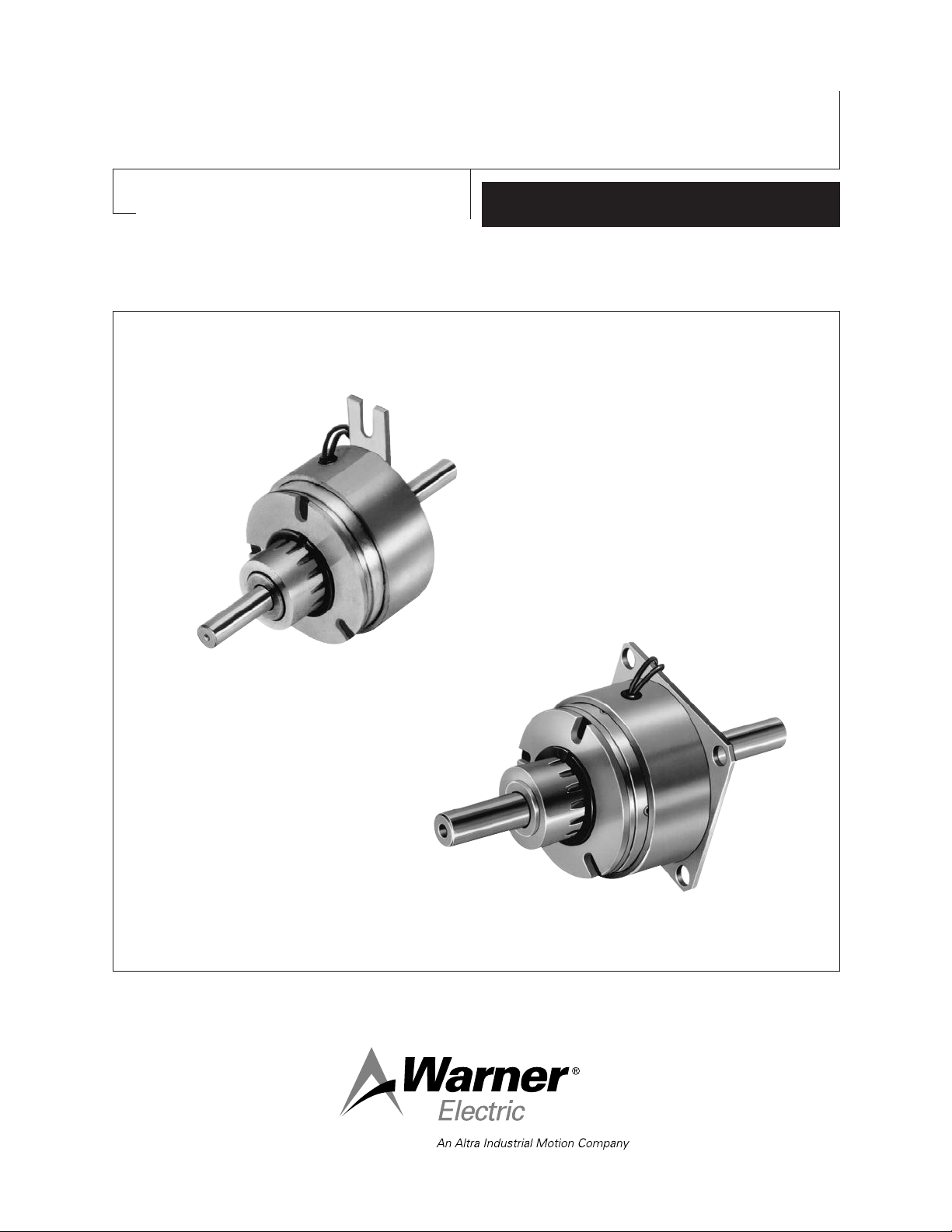
SF-120, SF-170, SF-250, SF-400 Bearing Mounted,
Flange Mounted, SFC-120, SFC-170, SFC-250,
SFC-400 Bearing Mounted, Flange Mounted
P-200
819-0481
Installation Instructions
Page 2
Contents
Mounting Examples and Options . . . . . . . . . . . . . . . . .3
Installation Instructions
SF-120, SF-170, SF-250, SF-400 . . . . . . . . . . . . .4
SFC-120, SFC-170, SFC-250, SFC-400 . . . . . . . .7
Electrical Coil Data . . . . . . . . . . . . . . . . . . . . . . . . . .11
Burnishing and Maintenance . . . . . . . . . . . . . . . . . . .12
Illustration Drawings
SF-120, SF-170 Flange Mounted . . . . . . . . .14-19
SF-120, SF-170 Bearing Mounted . . . . . . . . .18-21
SF-250, SF-400 Flange Mounted . . . . . . . . .22-25
SF-250, SF-400 Bearing Mounted . . . . . . . . .26-29
SFC-120, SFC-170 Flange Mounted . . . . . . .30-33
SFC-120, SFC-170 Bearing Mounted . . . . . .34-37
SFC-250, SFC-400 Flange Mounted . . . . . . .38-41
SFC-250, SFC-400 Bearing Mounted . . . . . .42-45
Warranty . . . . . . . . . . . . . . . . . . . . . . . . . . .Back Cover
Follow the installation instructions in this manual
carefully to ensure safe, reliable operation. All
stated or implied manufacturer warranties are
voided if this product is not installed in
accordance with these instructions.
Failure to follow these instructions
may result in product damage, equipment damage,
and serious or fatal injury to personnel.
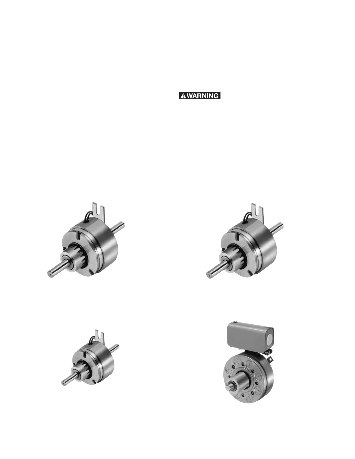
SF-120
SF-250
Warner Electric • 800-825-9050 P-200 • 819-0481
2
SF-170
SF-400
Page 3
Mounting Examples and Options
Warner Electric clutches are simple to
install. They consist of components
which must be assembled on the
shaft and properly attached to the
machine frame.
Various customer furnished drive
components must be assembled with
the clutch. Pulleys, sprockets and
bearings/pillow blocks for shafting
may be essential elements of a
complete drive system. Squareness
and concentricity tolerances are
specified where critical to proper
clutch/brake functioning.
The illustrations show SF, and SFC
Flange Mounted and Bearing
Mounted units mounted with
customer supplied bearing mounted
pulley. In each illustration the drive pin
for a normal duty clutch is shown. In
this manner the pulley will support
the armature.
SF Clutches and SFC Clutch Couplings
Flange Mounting
Concentricity tolerances, held by customer,
are critical. Pilot surface required on
machine member. Eliminates bearings.
Good design for high speed applications.
SF Clutch
Typical Installation
SFC Clutch Coupling
Typical Installation
Bearing Mounting
Bearing supports field and holds close tolerances
required between rotor and field. Easy to install
and priced about the same as the flange
mounted design.
SF Clutch
Typical Installation
SFC Clutch Coupling
Typical Installation
Warner Electric • 800-825-9050 P-200 • 819-0481
3
Page 4
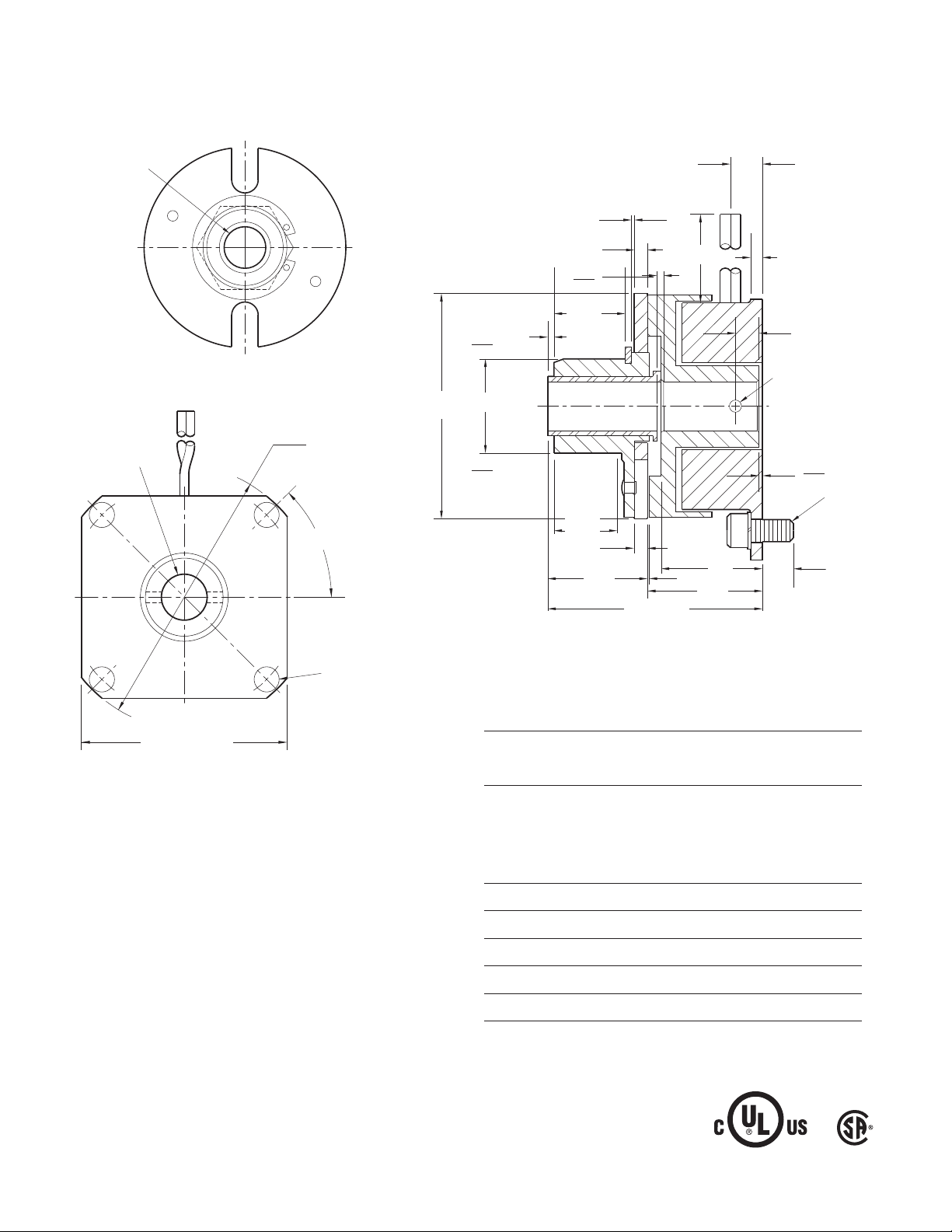
Clutch SF-120, SF-170, SF-250, SF-400
Field
Mounting
Surface
Pilot
Diameters
Installation Instructions
A. Installing the Conduit Box
To install the conduit box on the size 400 units, refer
to the instructions supplied with conduit box.
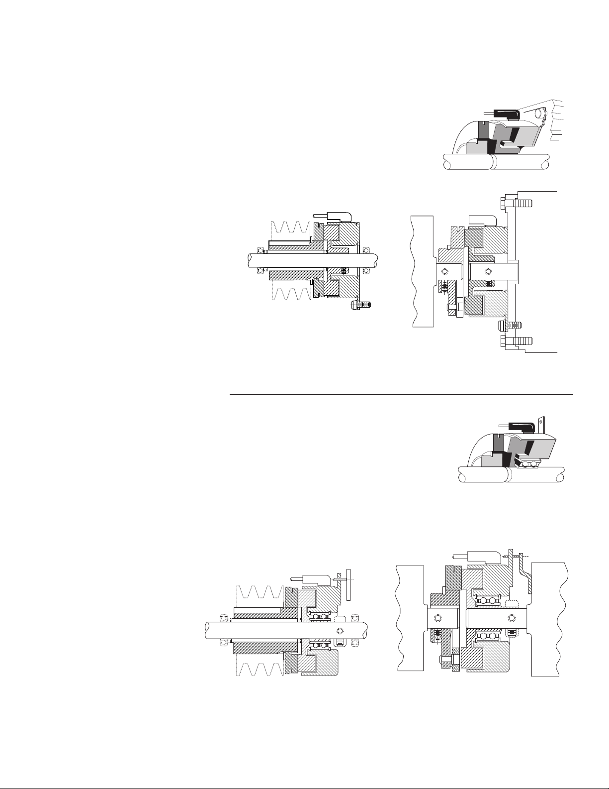
B. Mounting the Field-and-Rotor Assembly
Flange-Mounted Units
The fields and rotors are shipped separately for
flange-mounted units. On some applications it may
be necessary to mount the rotor first, and then bring
the field into position. In other instances the field
may be mounted first, and then the rotor (mounted
on a shaft) will be inserted into place.
Figure 2
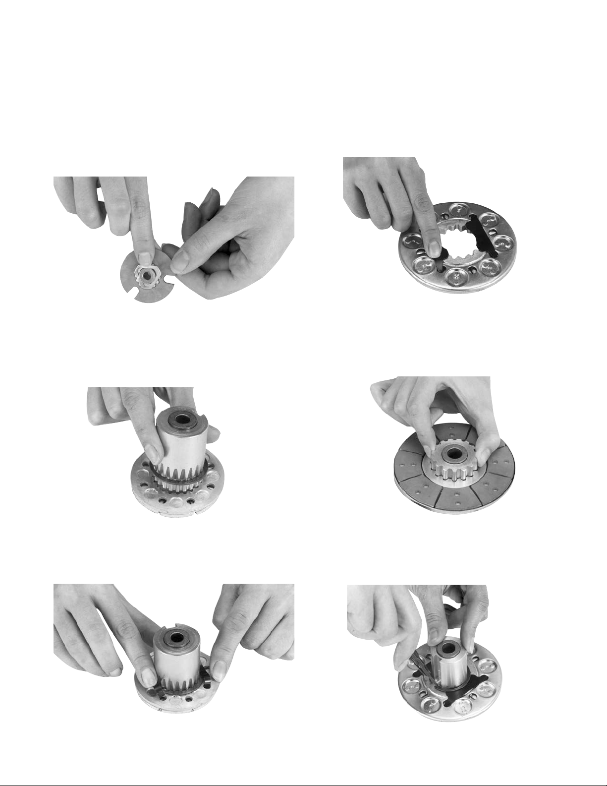
7. Secure the assembly in this position by
alternately tightening the two setscrews.
1. Care must be taken in selecting the location for
mounting the field assembly. Pilot diameters are
machined on the field mounting flange to aid in
holding the field in the proper position.
2. An appropriate pilot diameter must be provided
on the mounting surface as well. (Figure 1)
Figure 1
3. The field assembly is then fastened in place with
capscrews and lockwashers. (Figure 2)
4. After the unit is in place, the mounting face and
pilot must be square and concentric with the
shaft in accordance with the tolerances listed on
the drawings.
5. Insert a key into the shaft keyway.
6. Slide the rotor assembly onto the shaft over
the key.
8. Position the field and rotor in accordance with
the overall axial dimension shown on the
illustration drawings for correct size unit. Holding
this dimension will assure the proper clearance
between the field and rotor.
Bearing-Mounted Units
In bearing-mounted units, the field and rotor are
shipped as an assembly. Either this assembly or the
armature and hub assembly can be mounted on the
shaft first, depending on the characteristics on each
application.
1. Insert the key into the shaft keyway.
2. Slide the rotor assembly over the key and on to
the shaft.
3. Secure the field-and-rotor assembly in place by
alternately tightening the two set screws.
Note: The field-and-rotor assemblies for 120
units and 250 units, 1/2 inch bore,
are held in place by set screws
inserted into a set collar on the end of
the rotor hub extension. Secure these
assemblies in place by alternately
tightening the screws.
4. A tab or torque arm on the field is used to
prevent rotation of the field caused by normal
bearing drag. Insert either a pin in the U-slot or
a fork around the torque arm to prevent this
rotation. Under no circumstances, however,
should the field be so tightly restrained as to
preload the bearing.
Warner Electric • 800-825-9050 P-200 • 819-0481
4
Page 5
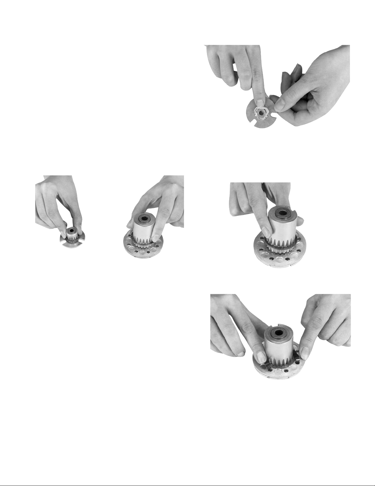
C. Assembling the Armature and Hub
The clutch units contain an extended armature hub
mounted on sleeve bearings. These hubs may be
adapted to a customer-supplied sheave, sprocket,
or gear for transmitting power to a parallel shaft.
1. The antibacklash armatures are shipped
assembled and ready to be installed. See
Section D.
2. The standard armature and hub must be
assembled before it can be installed. Assemble
the armatures so that the shiny surfaces size
(120 and 170) or backing plate sides size (250
and 400) are against the hub retainer ring
(Figure 3).
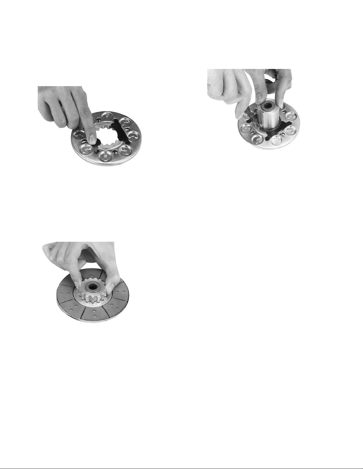
Figure 4
Insert both release springs into the holes of the
backing plate. Bow the springs as necessary to
insert them into the armature. (See Figure 6)
Figure 3
3. An optional release spring may be used with the
standard armatures and hubs. The release
spring forces the armature back against the hub
retainer ring when the magnet coil is
de-energized.
Follow these instructions to assemble the
armature and hub when the optional release
springs are being used.
SF-170
Assemble the splined armature to the hub. The
shiny side of the armature should be against the
hub retainer ring.
Assemble the release spring into the groove in
the hub spline. The curved portion of the spring
should be against the armature (Figure 4).
SF-250
Insert the hub, with snap ring intact, into the
armature from the backing plate side. (See
Figure 5)
Figure 5
Figure 6
Warner Electric • 800-825-9050 P-200 • 819-0481
5
Page 6
SF-400
Insert the release springs into the backing plate
holes of the armature. Bow the springs as necessary to insert them into the armature. (See
Figure 7)
Assemble the snap ring into the groove in the
hub, clamping the release spring against the
end of the spline. (See Figure 9)
Figure 9
Figure 7
Remove the snap ring from the hub.
Insert the hub, with the setscrew end first, into
the armature from the segmented side. Slide
the hub into the armature until the release
springs engage the snap ring groove. (See
Figure 8)
Figure 8
D. Mounting the Armature Assembly
1. Slide the armature assembly onto the shaft.
Position the assembly in accordance with the
overall axial dimensions given on the illustration
drawings.
2. The armature-hub assembly can be held in this
position with retainer rings, a set collar, a
shoulder on the shaft, or any combination of
these. The hub may need to be repositioned as
wear occurs with time.
Warner Electric • 800-825-9050 P-200 • 819-0481
6
Page 7
Clutch-Coupling SFC-120, SFC-170,
Field
Mounting
Surface
Pilot
Diameters
SFC-250, SFC-400
Installation Instructions
A. Aligning the Shafts
In order for the clutch-coupling unit to operate
properly, the mounting shafts of the motor and
reducer or other hardware must be aligned with
respect to each other before the unit is installed.
The two shafts should be concentric with each
other within .004 T.I.R., and angular alignment
should be within 1/2 degree.
B. Installing the Conduit Box
To install the conduit box on the size 400 units, refer
to the instructions supplied with conduit box.
C. Mounting the Field-and-Rotor Assembly
Flange-Mounted Units
The fields and rotors are shipped separately for
flange-mounted units. On some applications it will
be necessary to mount the rotor first, and then
bring the field into position. In other instances the
field will be mounted first, and then the rotor
(mounted on a shaft) will be inserted into place.
1. Care must be taken in selecting the location for
mounting the field assembly. Pilot diameters are
machined on the field mounting flange to aid in
holding the field in the proper position. (Figure
1)
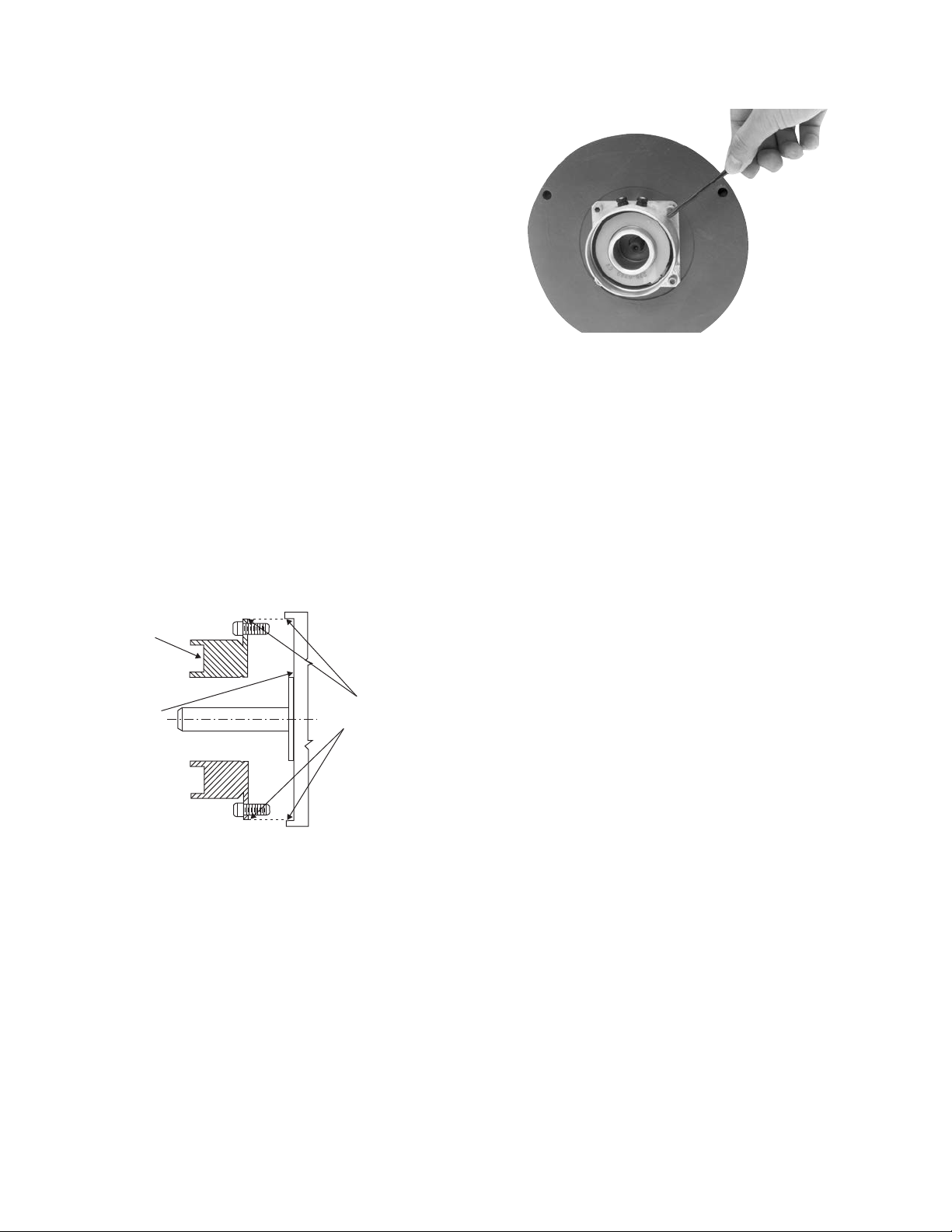
1. Use a straight-edge to check if the shafts are
aligned with each other. For a more precise
indication of alignment, use a dial indicator.
(Figure 10)
2. Adjust the position of the motor, reducer, or
other hardware as required to achieve the
2. An appropriate pilot diameter must be provided
on the mounting surface as well.
3. The field assembly is then fastened in place
with capscrews and lockwashers. (Figure 2)
Figure 1
correct alignment.
3. To be sure the shafts stay in alignment, drill
holes for tapered dowel pins through the
mounting bases of the motor, reducer, or other
hardware and into the mounting surfaces. This
procedure will ensure that, after the clutchcoupling has been installed, the shafts can
easily be placed in proper alignment again by
lining up the holes and secured by inserting the
dowel pins.
Warner Electric • 800-825-9050 P-200 • 819-0481
Figure 2
7
Page 8
4. After the unit is in place, the mounting face and
pilot diameter must be square and concentric
with the shaft in accordance with the tolerances
listed on the drawings.
5. Insert a key into the shaft keyway.
6. Slide the rotor assembly onto the shaft over the
key.
7. Secure the assembly in this position by
alternately tightening the two setscrews.
8. Position the field and rotor in accordance with
the overall axial dimension shown on the
illustration drawings. Holding this dimension will
assure the proper clearance between the field
and rotor.
Bearing-Mounted Units
In bearing-mounted units, the field and rotor are
shipped as an assembly. Either this assembly or the
armature and hub assembly can be mounted on the
shaft first, depending on the characteristics of each
application.
1. Insert the key into the shaft keyway.
2. Slide the rotor assembly over the key and on to
the shaft.
C. Assembling the Armature and Hub
1. The antibacklash armatures are shipped
assembled and ready to be installed. See
Section D.
2. The standard armature and hub must be
assembled before it can be installed. Assemble
the armatures so that the shiny surfaces size
(120 and 170) or backing plate sides size (250
and 400) are against the hub retainer ring
(Figure 3).
Figure 3
3. An optional release spring may be used with the
standard armatures and hubs. The release
spring forces the armature back against the hub
retainer ring when the magnet coil is
de-energized.
3. Secure the field-and-rotor assembly in place by
alternately tightening the two set screws.
Note: The field-and-rotor assemblies for 120
units and 250 units, 1/2 inch bore,
are held in place by set screws
inserted into a set collar on the end of
the rotor hub extension. Secure the
assembly in place by alternately
tightening the screws.
4. A tab or torque arm on the field is used to
prevent rotation of the field caused by normal
bearing drag. Insert either a pin in the U-slot or
a fork around the torque arm to prevent this
rotation. Under no circumstances, however,
should the field be so tightly restrained as to
preload the bearing.
Follow these instructions to assemble the
armature and hub when the optional release
springs are being used.
Warner Electric • 800-825-9050 P-200 • 819-0481
8
Page 9
SFC-170
Assemble the splined armature to the hub. The
shiny side of the armature should be against the
hub retainer ring.
SFC-400
Insert the release springs into the backing plate
holes of the armature. Bow the springs as
necessary to insert them into the armature. (See
Figure 7)
Assemble the release spring into the groove in the
hub spline. The curved portion of the spring should
be against the armature (Figure 4).
Figure 4
SFC-250
Insert the hub, with snap ring intact, into the
armature from the backing plate side. (See Figure 5)
Remove the snap ring from the hub.
Figure 7
Insert the hub, with the setscrew end first, into the
armature from the segmented side. Slide the hub
into the armature until the release springs engage
the snap ring groove. (See Figure 8.)
Figure 5
Insert both release springs into the holes of the
backing plate. Bow the springs as necessary to
insert them into the armature. (See Figure 6)
Figure 6
Warner Electric • 800-825-9050 P-200 • 819-0481
Assemble the snap ring into the groove in the hub,
clamping the release spring against the end of the
spline. (See Figure 9.)
Figure 8
Figure 9
9
Page 10

D. Mounting the Armature Assembly
1. SFC 250 and 400 size units.
Insert a key in the keyslot of the shaft and slide the
armature assembly onto the shaft.
2. (SFC120 do not use keyway)
Position the assembly to allow a gap of about 1/64
inch between the faces of the armature and magnet.
The overall axial dimension should be in accordance
with the dimensions specified on the illustration
drawings.
3. Secure the assembly in this position by alternately
tightening the two setscrews in the hub.
4. The hub may need to be repositioned as wear
occurs with time.
Electrical Coil Data
Unit Size SF/SFC 120 SF/SFC 170
Voltage – DC 6 24 90 6 24 90
Resistance @ 20°C — Ohms 6.32 104 1386 6.96 111.2 1506
Current — Amperes .949 .230 .065 .861 .215 .060
Watts 5.69 5.52 5.85 5.85 5.16 5.37
Coil Build-up — Milliseconds 12 12 11 17 17 16
Coil Decay — Milliseconds 8 878 76
Unit Size SF/SFC 250 SF/SFC 400
Voltage – DC 6 24 90 6 24 90
Resistance @ 20°C — Ohms 5 76.4 1079 4.88 73 1087
Current — Amperes 1.2 .314 .084 1.23 .322 .083
Watts 7.2 7.5 7.51 7.39 7.96 7.45
Coil Build-up — Milliseconds 48 48 44 154 154 154
Coil Decay — Milliseconds 15 15 13 62 60 55
Notes: Build-up time equals current to approximately 90% of steady state value and flux to 90%.
Decay time equals current to approximately 10% of steady state value and flux to 10%.
Approximately because current leads or lags flux by a small amount.
Warner Electric • 800-825-9050 P-200 • 819-0481
10
Page 11

Burnishing and Maintenance
Burnishing
Intimate metal to metal contact is essential between the
armature and the metal rings (poles) of the magnet or
rotor. Warner Electric clutches and brakes leave the
factory with the friction material slightly undercut to assure
good initial contact.
Normally, the desired wearing-in process occurs naturally
as the surfaces slip upon engagement. The time for
wear-in, which is necessary to obtain the ultimate torque
of the unit, will vary depending on speed, load, or cycle
duty.
If maximum torque is required immediately after
installation, the unit should be burnished by slipping the
friction surfaces together at reduced voltage. It is
recommended that the burnishings be done right on the
application, if at all possible.
Burnishing at high speed will result in a smoother wear-in
pattern and reduce the time for burnishing. The voltage
should be set at approximately 30% or 40% of the rated
value.
The unit should be cycled on and off to allow sufficient
time between slip cycles to prevent overheating.
When a Warner Electric brake or clutch is properly
assembled and installed, no further servicing, lubrication,
or maintenance should be required throughout the life of
the unit.
Maintenance
Wear Pattern: Wear grooves appear on the armature and
magnet surfaces. This is a normal wear condition, and
does not impair functioning of the unit. Normally, the
magnet and armature, as a mating pair, will wear at the
same rate. It is the usual recommendation that both components be replaced at the same time.
Heat: Excessive heat and high operating temperatures
are causes of rapid wear. Units, therefore, should be
ventilated as efficiently as possible, especially if the
application requires fast, repetitive cycle operation.
Foreign Materials: If units are used on machinery
where fine, abrasive dust, chips or grit are dispelled into
the atmosphere, shielding of the brake may be
necessary if maximum life is to be obtained.
Where units are used near gear boxes or transmissions
requiring frequent lubrication, means should be provided
to protect the friction surfaces from oil and grease to
prevent serious loss of torque.
Oil and grease accidentally reaching the friction surfaces
may be removed by wiping with a rag dampened with a
suitable cleaner, which leaves no residue. In performing
this operation, do not drench the friction material.
If the friction materials have been saturated with oil or
grease, no amount of cleaning will be completely
effective. Once such a unit has been placed back in
service, heat will cause the oil to boil to the surface,
resulting in further torque loss.
Torque Loss: If a brake or clutch slips or loses torque
completely, the initial check should be the input voltage
to the magnet as follows:
90-Volt Series: Connect a DC voltmeter with a range of
0-100 or more directly across the magnet terminals.
With the power on and the potentiometer turned up, a
normal reading is 90 volts, although 85 to 95 is
satisfactory. The reading should drop as the
potentiometer control is adjusted counterclockwise.
24-Volt Series: Use a DC voltmeter with a range of 030 volts or more. A normal reading is approximately 2226 volts.
Remachining the face of a worn armature is not
recommended. If a replacement armature is to be used
with a used magnet, it is necessary to remachine the worn
magnet face. In refacing a magnet: (1) machine only
enough material to clean up the complete face of the
magnet; (2) hold the face within .005" of parallel with the
mounting plate; and (3) undercut the molded facing
material .001" - .003" below the metal poles.
Warner Electric • 800-825-9050 P-200 • 819-0481
6-Volt Series: Use a DC voltmeter of approximately 015 volt range. A normal reading is from 5.5 to 6.5 volts.
The above checks normally are sufficient. Further
checks may be made as follows: a low range ammeter,
when connected in series with one magnet lead, will
normally indicate approximately .40 amperes for the 90
volt units, 1.0 ampere for the 24 volt, and 3.5 amperes
for the 6 volt series. These readings are with the power
on and the potentiometer control in the maximum
position.
11
Page 12

Ohmmeter checks should be made with the power off
and the circuit open (to be certain, disconnect one lead
to the magnet). Average resistance for the 90 volt series
is 220 ohms; for the 24 volt, 20 ohms; and for the 6 volt
series, 1.5 ohms. A very high or infinite resistance
reading would indicate an open coil.
If the above checks indicate that the proper voltage and
current is being supplied to the magnet, mechanical
parts should be checked to assure that they are in good
operating condition and properly installed.
Warner Electric • 800-825-9050 P-200 • 819-0481
12
Page 13

Warner Electric • 800-825-9050 P-200 • 819-0481
13
Page 14
SF-120 Clutch Flange Mounted
For Bore sizes see
chart below.
Std. Arm.
Antibacklash Arm.
Armature View
For Bore sizes see
chart below.
1.499/1.497
Pilot Dia.
45°
.130/.123 dia.
4 holes equally
spaced on 1.312
dia. B.C.*
1.234
Max. Dia.
.035/.004 (Std.)
.020/.008 (Anti.)
When New
.072 (Std.)
.072 (Anti.)
.020
.000
.375
(Std.)
.502
.031
.500
.515
.511
* Mounting holes are within .006 of true position relative to pilot diameter.
.375
(Anti.)
Std. Arm
Antibacklash Arm
.375
(Std.)
.375
(Anti.)
.528
1.171 Max.
12
*
.072 (Std.)
.072 (Anti.)
.625
.062
.065/.062 dia.
2 holes equally
spaced
.546
Bore Dimensions
.156
.109
.019
.000
#4-40
UNC-3A
.187
Max.
Rotor Armature
Field View
Bore Dia. Bore Dia.
.188/.187 .195/.190
.251/.250 .257/.252
.313/.312 —
Customer Shall Maintain:
1. Squareness of field mounting face with shaft with
.003 T.I.R. measured at pilot diameter.
2. Concentricity of field mounting pilot diameter with
rotor mounting shaft within .003 T.I.R.
Armature Shaft .187 – .250
Rotor Shaft .187 – .312
Static Torque 5 lb. in.
Maximum Speed 3,600 rpm
Standard Voltage D.C. 6, 24, 90
All dimensions are nominal unless otherwise noted.
Warner Electric • 800-825-9050 P-200 • 819-0481
14
Page 15

1B
1A-1
1A-2
1A
2
4
3
SF-120 Clutch Flange Mounted – Outside Mounted Drawing I-25508
Item Description Part Number Qty.
1A Armature and Hub
1A-1 Armature Hub 1
3/16" Bore 5602-541-009
1/4" Bore 5602-541-008
1A-2 Armature 110-0110 1
1B Antibacklash Armature 1
3/16" Bore 5602-111-002
1/4" Bore 5602-111-003
5/16" Bore 5602-111-007
2 Rotor 1
3/16" Bore 5602-751-004
1/4" Bore 5602-751-002
5/16" Bore 5602-751-003
3 Mounting Accessory 5101-101-001 1
4 Field 1
6 Volt 5602-451-003
24 Volt 5602-451-005
90 Volt 5602-451-007
How to Order:
1. Specify Type of Armature Desired.
2. Specify Bore Size for Item 1A-1 or 1B and Item 2.
3. Specify Voltage for Item 4.
Example:
SF-120 Clutch per I-25508 - 90 Volt
Standard Armature
1/4" Armature Hub Bore
1/4" Rotor Bore
These units meet standards set forth in UL508 and are
listed under guide card #NMTR2, file #59164.
These units are CSA certified under file #LR11543.
Warner Electric • 800-825-9050 P-200 • 819-0481
15
Page 16

SF-170 Clutch Flange Mounted
Std. Arm.
Antibacklash
Arm.
For Bore sizes & Keyway
sizes see chart below.
Armature View
For Bore sizes
see chart below.
2.437
2.435
45°
Pilot
Dia.
1.718
Max. Dia.
.484 (Std.)
.390 (Anti.)
When New
.035/.004 (Std.)
.021/.009 (Anti.)
.031
.751
.750
.633
.629
.086 (Std.)
.094 (Anti.)
.484
(Std.)
.390
(Anti.)
Std. Arm
Anti. Arm
.086
(Std.)
.094
(Anti.)
.632
.040
.000
*
1.703 Max.
12
.035/.004
.021/.009
.187
.750
.375
.062
.751/.750
pilot dia.
backing plate
only
#8-32
UNC-3A
.437
Max.
1
.160
.150
.204/.187 dia. 4 holes
equally spaced on
2.125 diameter.
Mounting holes are
1.812
within .010 of true position relative to pilot
diameter.
Field View
Customer Shall Maintain:
1. Squareness of field mounting face with shaft with
.003 T.I.R. measured at pilot diameter.
2. Concentricity of field mounting pilot diameter with
rotor mounting shaft within .003 T.I.R.
*Diameter over knurl.
Rotor Bore Dimensions
Rotor Keyway Armature
Bore Dia. Bore Dia.
.251/.250 .062/.031 .2522/.2507
.313/.312 .062/.031 .3145/.3130
.376/.375 .093/.047 .3773/.3755
Armature Shaft .250 – .375
Rotor Shaft .250 – .375
Static Torque 15 lb.in.
Maximum Speed 5,000 rpm
Standard Voltage D.C. 6, 24, 90
All dimensions are nominal unless otherwise noted.
Warner Electric • 800-825-9050 P-200 • 819-0481
16
Page 17

1A
1A-1
1A-2
1A-3
2
4
3
1B
SF-170 Clutch Flange Mounted – Outside Mounted Drawing I-25754
Item Description Part Number Qty.
1A Armature and Hub
1A-1 Armature Hub 1
1/4" Bore 5123-541-002
5/16" Bore 5123-541-003
3/8" Bore 5123-541-004
1A-2 Armature 110-0111 1
1A-3 Release Spring 808-0019 1
1B Antibacklash Armature 1
1/4" Bore 5603-111-033
5/16" Bore 5603-111-034
3/8" Bore 5603-111-035
2 Rotor 1
1/4" Bore 5603-751-028
5/16" Bore 5603-751-029
3/8" Bore 5603-751-030
3 Mounting Accessory 5102-101-001 1
4 Field 1
6 Volt 5603-451-047
24 Volt 5603-451-049
90 Volt 5603-451-051
How to Order:
1. Specify Type of Armature Desired.
2. Specify Bore Size for Item 1A-1 or 1B and Item 2.
3. Specify Voltage for Item 4.
Example:
SF-170 Clutch per I-25754 - 90 Volt
Antibacklash Armature
1/4" Armature Hub Bore
1/4" Rotor Bore
These units meet standards set forth in UL508 and are
listed under guide card #NMTR2, file #59164.
These units are CSA certified under file #LR11543.
Warner Electric • 800-825-9050 P-200 • 819-0481
17
Page 18

SF-120 Clutch Bearing Mounted
.156
Std. Arm.
Antibacklash
Arm.
For Bore sizes
see chart below.
.562
Armature View
.562
For Bore sizes
see chart below.
.125
45°
1.234
Max. Dia.
.502
.500
.515
.511
.031
.035/.004 (Std.)
When New
*Customer shall maintain dimension as noted.
.020/.008 (Anti.)
.072 (Std.)
.072 (Anti.)
.375
(Std.)
.375
(Anti.)
Std. Arm
Antibacklash Arm
.375
(Std.)
.375
(Anti.)
.072 (Std.)
.072 (Anti.)
.528
Max.
.020
12
.000
*
.035/.004 (Std.)
.020/.008 (Anti.)
1.406 Max.
.781
.859
.062
.218
.687
.093
Field View
.578
Bore Dimensions
.703
Rotor Armature
Bore Dia. Bore Dia.
.188/.187 .195/.190
.251/.250 .257/.252
.313/.312 —
Armature Shaft .187 – .250
Rotor Shaft .187 – .250
Static Torque 5 lb.in.
Maximum Speed 3,600 rpm
Standard Voltage D.C. 6, 24, 90
All dimensions are nominal unless otherwise noted.
Warner Electric • 800-825-9050 P-200 • 819-0481
18
Page 19

1B
1A-1
1A-2
2
3
4
1A
SF-120 Clutch Bearing Mounted Drawing I-25509
Item Description Part Number Qty.
1A Armature and Hub
1A-1 Armature Hub 1
3/16" Bore 5602-541-009
1/4" Bore 5602-541-008
1A-2 Armature 110-0110 1
1B Antibacklash Armature 1
3/16" Bore 5602-111-002
1/4" Bore 5602-111-003
5/16" Bore 5602-111-007
2 Rotor 1
3/16" Bore 5602-751-008
1/4" Bore 5602-751-006
5/16" Bore 5602-751-007
3 Field 1
4 Set Collar 5602-266-001 1
6 Volt 5602-451-021
24 Volt 5602-451-023
90 Volt 5602-451-025
How to Order:
1. Specify Type of Armature Desired.
2. Specify Bore Size for Item 1A-1 or 1B and Item 2.
3. Specify Voltage for Item 3.
Example:
SF-120 Clutch per I-25509 - 90 Volt
Standard Armature
1/4" Armature Hub Bore
These units meet standards set forth in UL508 and are
listed under guide card #NMTR2, file #59164.
These units are CSA certified under file #LR11543.
Warner Electric • 800-825-9050 P-200 • 819-0481
19
Page 20

SF-170 Clutch Bearing Mounted
Std. Arm.
Antibacklash
Arm.
For Bore sizes see
chart below.
Armature View
.187
.500
For Bore sizes
see chart below.
1.718
Max.
Dia.
.035/.004 (Std.)
.021/.009 (Anti.)
When New
.031
.751
.750
.633
†
.629
.086 (Std.)
.094 (Anti.)
.040/.000
.484
(Std.)
.390
(Anti.)
Std. Arm.
Anti. Arm.
.484
(Std.)
.390
(Anti.)
.632
Max.
1.203
12
.37
5
.062
*
.093
.625
.086 (Std.)
.094 (Anti.)
1.093
.250
1.062
1.750 Max. Dia.
Field View
Customer Shall Maintain:
*Customer shall maintain dimension as noted.
1.906 Max.
1.375
Bore Dimensions
Rotor Armature
Bore Dia. Bore Dia.
.251/.250 .2522/.2507
.313/.312 .3145/.3130
.376/.375 .3773/.3755
Armature Shaft .187 – .250
Rotor Shaft .250 – .375
Static Torque 15 lb.in.
Maximum Speed 5,000 rpm
Standard Voltage D.C. 6, 24, 90
† over knurl
Warner Electric • 800-825-9050 P-200 • 819-0481
20
All dimensions are nominal unless otherwise noted.
Page 21

1A
1A-1
1A-2
1A-3
2
3
4
1B
SF-170 Clutch Bearing Mounted Drawing I-25755
Item Description Part Number Qty.
1A Armature and Hub
1A-1 Armature Hub 1
1/4" Bore 5123-541-002
5/16" Bore 5123-541-003
3/8" Bore 5123-541-004
1A-2 Armature 110-0111 1
1A-3 Release Spring `808-0019 1
1B Antibacklash Armature 1
1/4" Bore 5603-111-033
5/16" Bore 5603-111-034
3/8" Bore 5603-111-035
2 Rotor 1
1/4" Bore 5603-751-019
5/16" Bore 5603-751-021
3/8" Bore 5603-751-020
3 Field 1
6 Volt 5603-451-039
24 Volt 5603-451-041
90 Volt 5603-451-043
4 Retainer Ring 748-0024 1
How to Order:
1. Specify Type of Armature Desired.
2. Specify Bore Size for Item 1A-1 or 1B and Item 2.
3. Specify Voltage for Item 3.
Example:
SF-170 Clutch per I-25755 - 90 Volt
Antibacklash Armature
1/4" Armature Hub Bore
These units meet standards set forth in UL508 and are
listed under guide card #NMTR2, file #59164.
These units are CSA certified under file #LR11543.
Warner Electric • 800-825-9050 P-200 • 819-0481
21
Page 22

SF-250 Clutch Flange Mounted
For Bore & Keyway sizes
see chart below.
For Bore & Keyway
sizes see chart
below.
.437
Armature View
24°
12°
.437
2.625
Max. Dia.
1.376
1.375
Dia.
.062
.750
Dia.
.135
.095
.750
1.250
1.125
*
.343 Max.
.015 When New
1.453 Min.
2
3.281 Max.
*Customer shall maintain dimension as noted.
.171
.468
.380/.370
.062
1.063
1.061
Pilot
Dia.
8-32 UNC-
3A
.437
Max.
45°
3.500
3.498
Pilot Dia.
*Mounting holes are within .010 of true position relative to pilot diameter.
Field View
.204/.187 dia. (4) holes
equally spaced on 3.125
dia.*
Customer Shall Maintain:
1. Squareness of field mounting face with shaft within
.003 T.I.R. measured at pilot diameter.
2. Concentricity of field mounting pilot diameter with
rotor mounting shaft within .003 T.I.R.
Bore and Keyway Dimensions
2.625 Sq.
Armature Keyway Rotor Keyway
Bore Dia. Bore Dia.
.3750/.3745 .376/.375 .093 x .046
.5000/.4995 .312 x .156 *.438/.437 .125 x .031
*.5625/.5620 x 1.250 .501/.500 .125 x .031
.6250/.6245
*Available on special order only.
Armature Shaft .375 – .625
Rotor Shaft .375 – .500
Static Torque 70 lb.in.
Maximum Speed 7,500 rpm
Standard Voltage D.C. 6, 24, 90
All dimensions are nominal unless otherwise noted.
Warner Electric • 800-825-9050 P-200 • 819-0481
22
Page 23

1
3
2
4
5
5-1
6
SF-250 Clutch Flange Mounted – Outside Mounted Drawing I-25520
Item Description Part Number Qty.
1 Armature Hub 1
3/8" Bore 5124-541-002
1/2" Bore 5124-541-003
5/8" Bore 5124-541-005
2 Armature 5124-111-001 1
3 Release Spring 5103-101-003 1
4 Rotor 1
3/8" Bore 5103-751-008
1/2" Bore 5103-751-010
5 Field 1
6 Volt 5103-451-002
24 Volt 5103-451-004
90 Volt 5103-451-007
5-1 Terminal Accessory 5103-101-002 1
6 Mounting Accessory 5102-101-001 1
How to Order:
1. Specify Bore Size for Item 1 and Item 4.
2. Specify Voltage for Item 5.
Example:
SF-250 Clutch per I-25520 - 90 Volt
3/8" Armature Hub Bore
3/8" Rotor Bore
These units meet standards set forth in UL508 and are
listed under guide card #NMTR2, file #59164.
These units are CSA certified under file #LR11543.
Warner Electric • 800-825-9050 P-200 • 819-0481
23
Page 24

SF-400 Clutch Flange Mounted
For Bore & Keyway
sizes see chart below.
Removable plug
in ends for 1/2"
conduit.
For Bore &
Keyway
sizes see
chart
below.
Armature View
3.750
4.687 Max.
4.234
Max. Dia.
1.376
1.375
Dia.
.062
.015 When New
.875
Dia.
.328 Max.
1.468
Min.
2.125
3.546 Max.
1.546
.082
.042
1.125
1.312
.192/.182
1.500
*
.937
3.562
.250
1.875
1.873
Pilot Dia.
1/4-20 UNC-
3A
.093
.609 Max.
5.625
5.623
Pilot
Dia.
.296/.280 dia. (4) holes equally spaced on
5.000 dia. Mounting holes are within .010 of
true position relative to pilot diameter.
45°
Field View
Customer Shall Maintain:
1. Squareness of field mounting face with shaft within
.003 T.I.R. measured at pilot diameter.
2. Concentricity of field mounting pilot diameter with
rotor mounting shaft within .003 T.I.R.
*3. Customer shall maintain dimension as noted.
4.250
Sq.
Bore and Keyway Dimensions
Armature Keyway Rotor Keyway
Bore Dia. Bore Dia.
.5000/.4995 .312 x .156 .501/.500 .125 x.062
.6250/.6245 x 1.25 .626/.625
.7500/.7495 .751/.750 .187 x .093
Armature Shaft .500 – .750
Rotor Shaft .500 – 1
Static Torque 270 lb.in.
Maximum Speed 4,500 rpm
Standard Voltage D.C. 6, 24, 90
All dimensions are nominal unless otherwise noted.
Warner Electric • 800-825-9050 P-200 • 819-0481
24
Page 25

1
3
2
4
5
5-1
6
7
SF-400 Clutch Flange Mounted – Outside Mounted Drawing I-25695
Item Description Part Number Qty.
1 Armature Hub 1
1/2" Bore 5125-541-002
5/8" Bore 5125-541-003
3/4" Bore 5125-541-004
2 Armature 5125-111-001 1
3 Release Spring 5104-101-003 1
4 Rotor 1
1/2" Bore 5104-751-033
5/8" Bore 5104-751-034
3/4" Bore 5104-751-035
7/8" Bore 5104-751-036
1" Bore 5104-751-037
5 Field 1
6 Volt 5104-451-032
24 Volt 5104-451-033
90 Volt 5104-451-034
5-1 Terminal Accessory 5103-101-002 1
6 Conduit Box 5200-101-010 1
7 Mounting Accessory 5104-101-002 1
How to Order:
1. Specify Bore Size for Items 1 and 4.
2. Specify Voltage for Item 5.
Example:
SF-400 Clutch per I-25695 - 90 Volt
3/4" Armature Hub Bore
3/4" Rotor Bore
These units, when used in conjunction with the correct
Warner Electric conduit box, meet the standards set of
UL508 and are listed under guide card #NMTR2, file
#59164.
These units are CSA certified under file #LR11543
Warner Electric • 800-825-9050 P-200 • 819-0481
25
Page 26

SF-250 Clutch Bearing Mounted
For Bore & Keyway sizes
see chart below.
Armature View
2.625
Max. Dia.
1.376
1.375
Dia.
.062
.343 Max.
.015 When New
.750
Dia.
1.453 Min.
2
3.468 Max.
*Customer shall maintain dimension as noted.
.125
.085
1.437
1.125
*
1.312
.468
.171 + .062
- 0
.062
.609
Dia.
.171
.187
.187
.937
For Bore & Keyway
sizes see chart
below.
45°
.500
.437
1.562
Rad.
Field View
24°
12°
1.750
Max.
Bore and Keyway Dimensions
Armature Keyway Rotor Keyway
Bore Dia. Bore Dia.
.3750/.3745 .376/.375 .093 x .046
.5000/.4995 .312 x .156 .438/.437* .125 x .062
.5625/.5620* x 1.25 .501/.500 .125 x .062
.6250/.6245
* Available on special order only.
Armature Shaft .375 – .625
Rotor Shaft .375 – .500
Static Torque 70 lb.in.
Maximum Speed 7,500 rpm
Standard Voltage D.C. 6, 24, 90
All dimensions are nominal unless otherwise noted.
Warner Electric • 800-825-9050 P-200 • 819-0481
26
Page 27

1
2
3
4
(Shipped Assembled)
4-1
4-2
4-3
4-2
4-4
4-4-1
4-5
SF-250 Clutch Bearing Mounted Drawing I-25521
Item Description Part Number Qty.
1 Armature Hub 1
3/8" Bore 5124-541-002
1/2" Bore 5124-541-003
5/8" Bore 5124-541-005
2 Release Spring 5103-101-003 1
3 Armature 5124-111-001 1
4 Field and Rotor Assembly 1
6 Volt – 3/8" Bore 5103-452-002
24 Volt – 3/8" Bore 5103-452-004
90 Volt – 3/8" Bore 5103-452-007
6 Volt – 1/2" Bore 5103-452-016
24 Volt – 1/2" Bore 5103-452-018
90 Volt – 1/2" Bore 5103-452-021
4-1 Rotor 1
3/8" Bore 5103-751-014
1/2" Bore 5103-751-016
4-2 Retainer Ring 748-0371 2
4-3 Ball Bearing 166-0108 1
4-4 Field 1
6 Volt 5103-451-018
24 Volt 5103-451-020
90 Volt 5103-451-023
4-4-1 Terminal Accessory 5103-101-002 1
4-5* Set Collar 266-0005 1
*Used with 1/2" Bore only.
How to Order:
1. Specify Bore Size for Item 1 and Item 4.
2. Specify Voltage for Item 4.
Example:
SF-250 Clutch per I-25521 - 90 Volt
1/2" Armature Hub Bore
1/2" Rotor Bore
These units meet standards set forth in UL508 and are
listed under guide card #NMTR2, file #59164.
These units are CSA certified under file #LR11543.
Warner Electric • 800-825-9050 P-200 • 819-0481
27
Page 28

SF-400 Clutch Bearing Mounted
For Bore & Keyway
sizes see chart below.
45°
.500
.187
Dia.
.187
.859
Armature View
3.750
2.312 Rad.
Removable plug
in ends for 1/2"
conduit.
4.687
Max.
1.546
1.218
.015 When New
4.234
1.376
1.375
Dia.
.062
.875
Dia.
1.468
Min.
.328 Max.
2.125
3.859 Max.
.090
.050
1.281
1.812
1.625
*
Max.
Dia.
For Bore &
Keyway sizes
see chart
below.
Bore and Keyway Dimensions
Armature Keyway Rotor Keyway
Bore Dia. Bore Dia.
.501/.500 .125 x.062
.5000/.4995 .312 x .156 .626/.625
.6250/.6245 x 1.25 .751/.750 .187 x .093
.7500/.7495 .876/.875
1.001/1.000
.062
3.562
1.375
Dia.
.203
.328
Armature .500 – .750
Field View
*Customer shall maintain dimension as noted.
Rotor Shaft .500 – 1
Static Torque 270 lb.in.
Maximum Speed 4,500 rpm
Standard Voltage D.C. 6, 24, 90
All dimensions are nominal unless otherwise
noted.
Warner Electric • 800-825-9050 P-200 • 819-0481
28
Page 29

1
2
3
4-1
4-3
4-4
4-4-1
4-2
5
4
(Shipped Assembled)
SF-400 Clutch Bearing Mounted Drawing I-25696
Item Description Part Number Qty.
1 Armature Hub 1
1/2" Bore 5125-541-002
5/8" Bore 5125-541-003
3/4" Bore 5125-541-004
2 Release Spring 5104-101-003 1
3 Armature 5125-111-001 1
4 Field and Rotor Assembly 1
6 Volt – 1/2" Bore 5104-452-052
24 Volt – 1/2" Bore 5104-452-053
90 Volt – 1/2" Bore 5104-452-054
6 Volt – 5/8" Bore 5104-452-055
24 Volt – 5/8" Bore 5104-452-056
90 Volt – 5/8" Bore 5104-452-057
6 Volt – 3/4" Bore 5104-452-058
24 Volt – 3/4" Bore 5104-452-059
90 Volt – 3/4" Bore 5104-452-060
4-1 Rotor 1
1/2" Bore 5104-751-043
5/8" Bore 5104-751-044
3/4" Bore 5104-751-045
4-2 Retainer Ring 748-0018 1
4-3 Ball Bearing 166-0150 1
4-4 Field 1
4-4-1 Terminal Accessory 5103-101-002 1
5 Conduit Box 5200-101-010 1
6 Volt 5104-451-038
24 Volt 5104-451-039
90 Volt 5104-451-040
How to Order:
1. Specify Bore Size for Items 1 and 4.
2. Specify Voltage for Item 4.
Example:
SF-400 Clutch per I-25696 - 90 Volt
3/4" Armature Hub Bore
3/4" Rotor Bore
These units, when used in conjunction with the correct
Warner Electric conduit box, meet standards set forth in
UL508 and are listed under guide card #NMTR2, file
#59164.
These units are CSA certified under file #LR11543
Warner Electric • 800-825-9050 P-200 • 819-0481
29
Page 30

SFC-120 Clutch Coupling Flange Mounted
Std. Arm.
Antibacklash
Arm.
For Bore sizes
see chart below.
Armature View
For Bore sizes
see chart below.
1.499/1.497
Pilot Dia.
1.234
Max.
Dia.
.015 When New
.072 (Std.)
.072 (Anti.)
.109 (Std.)
.140 (Anti.)
.500
Std. Arm
Antibacklash Arm.
.562
.072
(Std.)
.072
(Anti.)
.015
.343
12 Min.
.968 (Std.)
.968 (Anti.)
.546
.625
.156
.062
.109
.063/.062 dia.
(2) holes
equally
spaced.
.019
.000
#4-40 UNC-
.187
Max.
3A
45°
.130/.123 dia. (4)
holes equally
spaced on 1.312
dia. Mounting
holes are within
.006 of true position relative to pilot
diameter.
1.140 Max. Sq.
Field View
Customer Shall Maintain:
1. Squareness of field mounting face with rotor
shaft within .003 T.I.R. measured at pilot diameter.
2. Concentricity of field mounting pilot diameter
with rotor mounting shaft within .003 T.I.R.
3. Rotor and armature shafts in line within .003 T.I.R.
Bore Dimensions
Rotor Armature
Bore Dia. Bore Dia.
.188/.187 .188/.187
.251/.250 .251/.250
.313/.312 (.313/.312)*
*(Antibacklash Armatures)
Armature Shaft .187 – .250
Rotor Shaft .187 – .312
Static Torque 5 lb. in.
Maximum Speed 3,600 rpm
Standard Voltage D.C. 6, 24, 90
All dimensions are nominal unless otherwise noted.
Warner Electric • 800-825-9050 P-200 • 819-0481
30
Page 31

1B
1A-1
1A-2
2
4
1A
3
SFC-120 Clutch Coupling Flange Mounted – Outside Mounted Drawing I-25503
Item Description Part Number Qty.
1A Armature and Hub
1A-1 Armature Hub 1
1A-2 Armature 110-0110 1
1B Antibacklash Armature 1
2 Rotor 1
3 Mounting Accessory 5101-101-001 1
4 Field 1
3/16" Bore 5622-541-009
1/4" Bore 5622-541-008
3/16" Bore 5622-111-004
1/4" Bore 5622-111-002
5/16" Bore 5622-111-003
3/16" Bore 5602-751-004
1/4" Bore 5602-751-002
5/16" Bore 5602-751-003
6 Volt 5602-451-003
24 Volt 5602-451-005
90 Volt 5602-451-007
How to Order:
1. Specify Type of Armature Desired.
2. Specify Bore Size for Item 1A-1 or 1B and Item 2.
3. Specify Voltage for Item 4.
Example:
SFC-120 Clutch per I-25503 - 90 Volt
Standard Armature
1/4" Armature Hub Bore
1/4" Rotor Bore
These units meet standards set forth in UL508 and are
listed under guide card #NMTR2, file #59164.
These units are CSA certified under file #LR11543.
Warner Electric • 800-825-9050 P-200 • 819-0481
31
Page 32

SFC-170 Clutch Coupling Flange Mounted
.375
.015 When New
Std. Arm.
Antibacklash
Arm.
For Bore & Keyway sizes
see chart below.
Armature View
For Bore sizes
see chart
below.
2.437
2.435
Dia.
45°
1.718
Max.
Dia.
.125 (Std.)
.109 (Anti.)
.625
(Std.)
(Anti.)
.086 (Std.)
.094 (Anti.)
.086 (Std.)
.094 (Anti.)
.843
.515
Max.
12
.015
1.375 (Std.)
1.359 (Anti.)
.187
.750
.062
.752
.750
Pilot Dia.
Backing Plate Only
#8-32
UNC-3A
.437
Max.
.160/.150
.204/.187 dia.
(4) holes
equally spaced
on 2.125 dia.
Mounting holes
are within .010
of true position
relative to pilot
diameter.
1.812 Max. Sq.
Field View
Customer Shall Maintain:
1. Squareness of field mounting face with
rotor shaft within .003 T.I.R. measured at pilot
diameter.
2. Concentricity of field mounting pilot diameter
with rotor mounting shaft within .003 T.I.R.
3. Rotor and armature shafts in line within .003 T.I.R.
Bore Dimensions
Rotor Armature
Bore Dia. Keyway Bore Dia.
.251/.250 .062 x .031 .251/.250
.313/.312 .062 x .031 .313/.312
.376/.375 .093 x .046 .376/.375
Armature Shaft .250 – .375
Rotor Shaft .250 – .375
Static Torque 15 lb. in.
Maximum Speed 5,000 rpm
Standard Voltage D.C. 6, 24, 90
All dimensions are nominal unless otherwise noted.
Warner Electric • 800-825-9050 P-200 • 819-0481
32
Page 33

1A-1
1A
1A-2
1A-3
1B
3
2
4
SFC-170 Clutch Coupling Flange Mounted – Outside Mounted Drawing I-25756
Item Description Part Number Qty.
1A Armature and Hub
1A-1 Armature Hub 1
1/4" Bore 5102-541-002
5/16" Bore 5102-541-003
3/8" Bore 5102-541-004
1A-2 Armature 110-0111 1
1A-3 Release Spring 808-0019 1
1B Antibacklash Armature 1
1/4" Bore 5623-111-008
5/16" Bore 5623-111-009
3/8" Bore 5623-111-010
2 Rotor 1
1/4" Bore 5603-751-028
5/16" Bore 5603-751-029
3/8" Bore 5603-751-030
3 Mounting Accessory 5102-101-001 1
4 Field 1
6 Volt 5603-451-047
24 Volt 5603-451-049
90 Volt 5603-451-051
How to Order:
1. Specify Type of Armature Desired.
2. Specify Bore Size for Item 1A-1 or 1B and Item 2.
3. Specify Voltage for Item 4.
Example:
SFC-170 Clutch per I-25756 - 90 Volt
Antibacklash Armature
1/4" Armature Hub Bore
1/4" Rotor Bore
These units meet standards set forth in UL508 and are
listed under guide card #NMTR2, file #59164.
These units are CSA certified under file #LR11543.
Warner Electric • 800-825-9050 P-200 • 819-0481
33
Page 34

SFC-120 Clutch Coupling Bearing Mounted
.015 When New
.072 (Std.)
.072 (Anti.)
.156
.062
12
.218
Std. Arm.
Antibacklash
Arm.
For Bore sizes
see chart below.
Armature View
.562
For Bore
sizes
see chart
below.
.125
45°
.109 (Std.)
.140 (Anti.)
.500
(Std.)
1.234
Max.
Dia.
.562
(Anti.)
.072 (Std.)
.072 (Anti.)
.015
Bore Dimensions
Rotor Armature
Bore Dia. Bore Dia.
.188/.187 .188/.187
.251/.250 .251/.250
.313/.312 (.313/.312)*
.781
.859
1.203 Max.
.093
.687
Dia.
*(Antibacklash Armatures)
.578
.703
Armature Shaft .187 – .250
Field View
Rotor Shaft .187 – .312
Static Torque 5 lb. in.
Maximum Speed 3,600 rpm
Customer Shall Maintain:
1. Alignment between rotor and armature shafts to be
.003 T.I.R.
Warner Electric • 800-825-9050 P-200 • 819-0481
34
Standard Voltage D.C. 6, 24, 90
All dimensions are nominal unless otherwise noted.
Page 35

1B
1A-1
2
1A-2
1A
3
4
SFC-120 Clutch Coupling Bearing Mounted Drawing I-25504
Item Description Part Number Qty.
1A Armature and Hub
1A-1 Armature Hub 1
3/16" Bore 5622-541-009
1/4" Bore 5622-541-008
1A-2 Armature 110-0110 1
1B Antibacklash Armature 1
2 Rotor 1
3 Field 1
4 Set Collar 5602-266-001 1
3/16" Bore 5622-111-004
1/4" Bore 5622-111-002
5/16" Bore 5622-111-003
3/16" Bore 5602-751-008
1/4" Bore 5602-751-006
5/16" Bore 5602-751-007
6 Volt 5602-451-021
24 Volt 5602-451-023
90 Volt 5602-451-025
How to Order:
1. Specify Type of Armature Desired.
2. Specify Bore Size for Item 1A-1 or 1B and Item 2.
3. Specify Voltage for Item 3.
Example:
SFC-120 Clutch per I-25504 - 90 Volt
Standard Armature
1/4" Armature Hub Bore
These units meet standards set forth in UL508 and are
listed under guide card #NMTR2, file #59164.
These units are CSA certified under file #LR11543.
Warner Electric • 800-825-9050 P-200 • 819-0481
35
Page 36

SFC-170 Clutch Coupling Bearing Mounted
.375
Std. Arm.
Antibacklash
Arm.
Armature View
1.87
.500
For Bore sizes
see chart below.
1.718
Max.
Dia.
.086 (Std.)
.094 (Anti.)
.015 When New
.125 (Std.)
.109 (Anti.)
.625
(Std.)
.843
(Anti.)
12
.015
.086 (Std.)
.094 (Anti.)
1.562 Max.
1.093
1.203
.062
.093
.625
Dia.
.250
For Bore sizes
see chart below.
1.375
1.062
1.750 Max. Dia.
Field View
Customer Shall Maintain:
1. Alignment between rotor and armature shafts to be
.003 T.I.R.
Bore Dimensions
Rotor Armature
Bore Dia. Bore Dia.
.251/.250 .251/.250
.313/.312 .313/.312
.376/.375 .376/.375
Armature Shaft .250 – .375
Rotor Shaft .250 – .375
Static Torque 15 lb. in.
Maximum Speed 5,000 rpm
Standard Voltage D.C. 6, 24, 90
All dimensions are nominal unless otherwise noted.
Warner Electric • 800-825-9050 P-200 • 819-0481
36
Page 37

1A
1A-1
1A-2
1B
1A-3
2
3
4
SFC-170 Clutch Coupling Bearing Mounted Drawing I-25757
Item Description Part Number Qty.
1A Armature and Hub
1A-1 Armature Hub 1
1/4" Bore 5102-541-002
5/16" Bore 5102-541-003
3/8" Bore 5102-541-004
1A-2 Armature 110-0111 1
1A-3 Release Spring 808-0019 1
1B Antibacklash Armature 1
1/4" Bore 5623-111-008
5/16" Bore 5623-111-009
3/8" Bore 5623-111-010
2 Rotor 1
1/4" Bore 5603-751-019
5/16" Bore 5603-751-021
3/8" Bore 5603-751-020
3 Field 1
6 Volt 5603-451-039
24 Volt 5603-451-041
90 Volt 5603-451-043
4 Retainer Ring 748-0024 1
How to Order:
1. Specify Type of Armature Desired.
2. Specify Bore Size for Item 1A-1 or 1B and Item 2.
3. Specify Voltage for Item 3.
Example:
SFC-170 Clutch per I-25757 - 90 Volt
Antibacklash Armature
1/4" Armature Hub Bore
These units meet standards set forth in UL508 and are
listed under guide card #NMTR2, file #59164.
These units are CSA certified under file #LR11543.
Warner Electric • 800-825-9050 P-200 • 819-0481
37
Page 38

SFC-250 Clutch Coupling Flange Mounted
For Bore & Keyway sizes
see chart below.
Std. Arm.
Antibacklash
Arm.
For Bore & Key-
way sizes see
chart below.
.437 Max.
Armature View
24°
12°
.437 Max.
2.625
Max.
Dia.
.015 When New
.171 (Std.)
.562 (Anti.)
1.187
(Std.)
1.390
(Anti.)
.171
Max.
.015
.687
.546
.343
Max.
.171
.750
1.968 (Std.)
1.984 (Anti.)
1.125
1.250
.468
.062
.380/.370
1.063
1.061
Pilot Dia.
Backing Plate
Only
8-32 UNC3A
.437
Max.
45°
3.500/3.498
Pilot Dia.
.204/.187 dia. (4) holes equally spaced on
3.125 dia. Mounting holes are within .010 of
true position relative to pilot diameter.
Field View
Customer Shall Maintain:
1. Squareness of field mounting face with rotor shaft
within .003 T.I.R. measured at pilot diameter.
2. Concentricity of field mounting pilot diameter with
rotor mounting shaft within .003 T.I.R.
3. Rotor and armature shafts in line within .003 T.I.R.
Bore and Keyway Dimensions
2.625 Sq.
Armature Keyway Rotor Keyway
Bore Dia. Bore Dia.
.376/.375 .093 x .046
*.438/.437 .376/.375 .093 x .046
.501/.500 .125 x .062 *.438/.437 .125x .062
*.563/.562 .501/.500
.626/.625
*.688/.687 .187 x .093
.751/.750
* Available on special order only.
Armature Shaft .375 – .750
Rotor Shaft .375 – .500
Static Torque 70 lb. in.
Maximum Speed 7,500 rpm
Standard Voltage D.C. 6, 24, 90
All dimensions are nominal unless otherwise noted.
Warner Electric • 800-825-9050 P-200 • 819-0481
38
Page 39

1A-1
1A-3
1A
1A-2
2
4
3
3-1
1B
SFC-250 Clutch Coupling Flange Mounted Outside Mounted Drawing I-25522
Item Description Part Number Qty.
1A Armature and Hub
1A-1 Armature Hub 1
3/8" Bore 5103-541-002
1/2" Bore 5103-541-004
5/8" Bore 5103-541-006
3/4" Bore 5103-541-008
1A-2 Armature 5124-111-001 1
1A-3 Release Spring 5103-101-003 1
1B Antibacklash Armature 1
2 Rotor 1
3 Field 1
3-1 Terminal Accessory 5103-101-002 1
4 Mounting Accessory 5102-101-001 1
3/8" Bore 5365-111-003
1/2" Bore 5365-111-005
5/8" Bore 5365-111-007
3/4" Bore 5365-111-009
3/8" Bore 5103-751-008
1/2" Bore 5103-751-010
6 Volt 5103-451-002
24 Volt 5103-451-004
90 Volt 5103-451-007
How to Order:
1. Specify Type of Armature Desired.
2. Specify Bore Size for Item 1A-1 or 1-B and Item 2.
3. Specify Voltage for Item 3.
Example:
SFC-250 Clutch Coupling per I-25522 - 90 Volt
Standard Armature
1/2" Armature Hub Bore
1/2" Rotor Bore
These units meet standards set forth in UL508 and are
listed under guide card #NMTR2, file #59164.
These units are CSA certified under file #LR11543.
Warner Electric • 800-825-9050 P-200 • 819-0481
39
Page 40

SFC-400 Clutch Coupling Flange Mounted
For Bore & Keyway sizes
see chart below.
Std. Arm.
Antibacklash
Arm.
Removabl
e plug in
ends for
1/2"
conduit.
For Bore
& Keyway
sizes see
chart
below.
Armature View
3.750
4.687
.015 When New
.187 (Std.)
.218 (Anti.)
1.250
4.234
Max.
Dia.
1.640
.187 (Std.)
.218 (Anti.)
.328 Max.
(Std.)
(Anti.)
.328
.875
.671
.828
.015
1.546
2.328/2.359
1.125
1.312
1.500
1.50
.937
3.562
.093
.250
1.875
1.873
Pilot Dia.
1/4-20
UNC-3A
.192/.182
.609 Max.
5.626
5.623
Pilot Dia.
.296/.280 dia. (4) holes equally spaced on 5.000 dia.*
Field View
Customer Shall Maintain:
1. Squareness of field mounting face with rotor shaft
within .003 T.I.R. measured at pilot
diameter.
2. Concentricity of field mounting pilot diameter with
rotor mounting shaft within .003 T.I.R.
3. Rotor and armature shafts in line within .003 T.I.R.
4.250 Sq.
45°
*Mounting holes are within .010 of true position relative to pilot diame-
ter.
Bore and Keyway Dimensions
Armature Keyway Rotor Keyway
Bore Dia. Bore Dia.
.501/.500 .125 x .062 .501/.500 .125 x.062
*.563/.562
.626/.625 .626/.625
*.688/.687 .187 x .093 .751/.750 .187 x .093
.751/.750 .876/.875
.876/.875 1.001/1.000
*Available on special order only
Armature Shaft .500 – .875
Rotor Shaft .500 – 1
Static Torque 270 lb. in.
Maximum Speed 4,500 rpm
Standard Voltage D.C. 6, 24, 90
All dimensions are nominal unless otherwise noted.
Warner Electric • 800-825-9050 P-200 • 819-0481
40
Page 41

1A-1
1A-3
1A
1A-2
2
3
5
3-1
4
1B
SFC-400 Clutch Coupling Flange Mounted – Outside Mounted Drawing I-25697
Item Description Part Number Qty.
1A Armature and Hub
1A-1 Armature Hub 1
1/2" Bore 5104-541-002
5/8" Bore 5104-541-004
3/4" Bore 5104-541-006
7/8" Bore 5104-541-007
1A-2 Armature 5125-111-001 1
1A-3 Release Spring 5104-101-003 1
1B Antibacklash Armature 1
1/2" Bore 5367-111-003
5/8" Bore 5367-111-005
3/4" Bore 5367-111-007
7/8" Bore 5367-111-008
2 Rotor 1
1/2" Bore 5104-751-033
5/8" Bore 5104-751-034
3/4" Bore 5104-751-035
7/8" Bore 5104-751-036
1" Bore 5104-751-037
3 Field 1
6 Volt 5104-451-032
24 Volt 5104-451-033
90 Volt 5104-451-034
3-1 Terminal Accessory 5103-101-002 1
4 Conduit Box 5200-101-010 1
5 Mounting Accessory 5104-101-002 1
How to Order:
1. Specify Type of Armature Desired.
2. Specify Bore Size for Item 1A-1 or 1B and Item 2.
3. Specify Voltage for Item 3.
Example:
SFC-400 Clutch Coupling per I-25697 - 90 Volt
3/4" Armature Hub Bore
3/4" Rotor Bore
These units, when used in conjunction with the correct
Warner Electric conduit box, meet standards set forth in
UL508 and are listed under guide card #NMTR2, file
#59164.
These units are CSA certified under file #LR11543.
Warner Electric • 800-825-9050 P-200 • 819-0481
41
Page 42

SFC-250 Clutch Coupling Bearing Mounted
For Bore & Keyway sizes
see chart below.
Std. Arm.
Antibacklash
Arm.
.187 Dia.
.187
Armature View
45°
.500 12°
.437
Max.
1.562 Rad.
24°
1.750 Max.
2.625
Max.
Dia.
.687 (Std.)
.718 (Anti.)
1.187
(Std.)
1.390
(Anti.)
.171 (Std.)
.187 (Anti.)
.343 Max.
.015 (Std.)
.015 (Anti.)
when new
.687
(Std.)
.718
(Anti.)
2.156 (Std.)
2.171 (Anti.)
1.437
1.125
.015 (Std.)
.015 (Anti.)
1.312
Bore and Keyway Dimensions
.468
.062 -0
.062
.609
Dia.
.171 +
.171
.937
For Bore & Keyway sizes
see chart below.
Field View
Customer Shall Maintain:
1. Armature shaft to be concentric with rotor shaft
within .003 T.I.R.
Armature Keyway Rotor Keyway
Bore Dia. Bore Dia.
.375/.376 .093 x .046 .376/.375 .093 x .046
*.438/.437
.501/.500 .125 x .062 *.438/.437 .125 x .062
*.563/.562 .501/.500
.626/.625
*.688/.687 .187 x .093
.751/.750
* Available on special order only.
Armature Shaft .375 – .750
Rotor Shaft .375 – .500
Static Torque 70 lb. in.
Maximum Speed 7,500 rpm
Standard Voltage D.C. 6, 24, 90
All dimensions are nominal unless otherwise noted.
Warner Electric • 800-825-9050 P-200 • 819-0481
42
Page 43

1B
1A-1
1A
1A-3
1A-2
2-1
2-2
2-3
2
(Shipped Assembled)
2-2
2-4
2-5
2-4-1
SFC-250 Clutch Coupling Bearing Mounted Drawing I-25523
Item Description Part Number Qty.
1A Armature and Hub
1A-1 Armature Hub 1
3/8" Bore 5103-541-002
1/2" Bore 5103-541-004
5/8" Bore 5103-541-006
3/4" Bore 5103-541-008
1A-2 Armature 5124-111-001 1
1A-3 Release Spring 5103-101-003 1
1B Antibacklash Armature 1
3/8" Bore 5365-111-003
1/2" Bore 5365-111-005
5/8" Bore 5365-111-007
3/4" Bore 5365-111-009
2 Field and Rotor Assembly 1
6 Volt – 3/8" Bore 5103-452-002
24 Volt – 3/8" Bore 5103-452-004
90 Volt – 3/8" Bore 5103-452-007
6 Volt – 1/2" Bore 5103-452-016
24 Volt – 1/2" Bore 5103-452-018
90 Volt – 1/2" Bore 5103-452-021
2-1 Rotor 1
2-2 Retainer Ring 748-0371 2
2-3 Ball Bearing 166-0108 1
2-4 Field 1
3/8" Bore 5103-751-014
1/2" Bore 5103-751-016
Item Description Part Number Qty.
6 Volt 5103-451-018
24 Volt 5103-451-020
90 Volt 5103-451-023
2-4-1 Terminal Accessory 5103-101-002 1
2-5 Set Collar* 266-0005 1
*Used with 1/2" Bore only.
How to Order:
1. Specify Type of Armature Desired.
2. Specify Bore Size for Item 1A-1 or 1B and Item 2.
3. Specify Voltage for Item 2.
Example:
SFC-250 Clutch Coupling per I-25523 - 90 Volt
Standard Armature
1/2" Armature Hub Bore
1/2" Rotor Bore
These units meet standards set forth in UL508 and are
listed under guide card #NMTR2, file #59164. These
units are CSA certified under file #LR11543.
Warner Electric • 800-825-9050 P-200 • 819-0481
43
Page 44

SFC-400 Clutch Coupling Bearing Mounted
For Bore & Keyway sizes
see chart below.
Std. Arm.
Antibacklash
Arm.
45°
Armature View
3.750
4.687
Remov-
able
plug in
ends for
1/2"
conduit.
.015 (Std.)
.015 (Anti.) when
new
.328 Max.
.875 (Std.)
.843 (Anti.)
1.250
4.234
(Std.)
Max.
Dia.
1.640
(Anti.)
.187 (Std.)
.218 (Anti.)
.875 (Std.)
.843 (Anti.)
.015
1.546
1.281
(Std.)
1.812
1.625
2.640 (Std.)
2.734 (Anti.)
1.218
3.562
1.375
Dia.
.062 (Std.)
.203 (Anti.)
.328 (Anti.)
.500
.187
.187
2.312
.859
For Bore & Keyway
sizes see chart
below.
Field View
Customer Shall Maintain:
1. Armature shaft to be concentric with rotor
shaft within .003 T.I.R.
Bore and Keyway Dimensions
Armature Keyway Rotor Keyway
Bore Dia. Bore Dia.
.501/.500 .125 x .062 .501/.500 .125 x.062
*.563/.562
.626/.625 .626/.625
*.688/.687 .187 x .093 .751/.750 .187 x .093
.751/.750 .876/.875
.876/.875 1.001/1.000
* Available on special order only.
Armature Shaft .500 – .875
Rotor Shaft .500 – 1
Static Torque 270 lb. in.
Maximum Speed 4,500 rpm
Standard Voltage D.C. 6, 24, 90
All dimensions are nominal unless otherwise noted.
Warner Electric • 800-825-9050 P-200 • 819-0481
44
Page 45

1B
1A-1
1A-3
1A-2
2-1
1-A
2
(Shipped Assembled)
2-3
2-4
2-4-1
2-2
3
SFC-400 Clutch Coupling Bearing Mounted Drawing I-25698
Item Description Part Number Qty.
1A Armature and Hub
1A-1 Armature Hub 1
1/2" Bore 5104-541-002
5/8" Bore 5104-541-004
3/4" Bore 5104-541-006
7/8" Bore 5104-541-007
1A-2 Armature 5125-111-001 1
1A-3 Release Spring 5104-101-003 1
1B Antibacklash Armature 1
1/2" Bore 5367-111-003
5/8" Bore 5367-111-005
3/4" Bore 5367-111-007
7/8" Bore 5367-111-008
2 Field and Rotor Assembly 1
6 Volt – 1/2" Bore 5104-452-052
24 Volt – 1/2" Bore 5104-452-053
90 Volt – 1/2" Bore 5104-452-054
6 Volt – 5/8" Bore 5104-452-055
24 Volt – 5/8" Bore 5104-452-056
90 Volt – 5/8" Bore 5104-452-057
6 Volt – 3/4" Bore 5104-452-058
24 Volt – 3/4" Bore 5104-452-059
90 Volt – 3/4" Bore 5104-452-060
6 Volt – 7/8" Bore 5104-452-061
24 Volt – 7/8" Bore 5104-452-062
90 Volt – 7/8" Bore 5104-452-063
6 Volt – 1" Bore 5104-452-064
24 Volt – 1" Bore 5104-452-065
90 Volt – 1" Bore 5104-452-066
2-1 Rotor 1
1/2" Bore 5104-751-043
Item Description Part Number Qty.
5/8" Bore 5104-751-044
3/4" Bore 5104-751-045
7/8" Bore 5104-751-046
1" Bore 5104-751-047
2-2 Retainer Ring 748-0018 1
2-3 Ball Bearing 166-0150 1
2-4 Field 1
6 Volt 5104-451-038
24 Volt 5104-451-039
90 Volt 5104-451-040
2-4-1 Terminal Accessory 5103-101-002 1
3 Conduit Box 5200-101-010 1
How to Order:
1. Specify Type of Armature Desired.
2 Specify Bore Size for Item 1A-1 or 1-B and
Item 2.
3. Specify Voltage for Item 2.
Example:
SFC-400 Clutch Coupling per I-25698 - 90 Volt
Antibacklash Armature
3/4" Armature Hub Bore
3/4" Rotor Bore
These units meet standards set forth in UL508 and are
listed under guide card #NMTR2, file #59164. These units
are CSA certified under file #LR11543.
Warner Electric • 800-825-9050 P-200 • 819-0481
45
Page 46

Warranty
Warner Electric LLC warrants that it will repair or replace (whichever it deems advisable) any
product manufactured and sold by it which proves to be defective in material or workmanship
within a period of one (1) year from the date of original purchase for consumer, commercial or
industrial use.
This warranty extends only to the original purchaser and is not transferable or assignable without
Warner Electric LLC’s prior consent.
Warranty service can be obtained in the U.S.A. by returning any defective product, transportation
charges prepaid, to the appropriate Warner Electric LLC factory. Additional warranty information
may be obtained by writing the Customer Satisfaction Department, Warner Electric LLC, 449
Gardner Street, South Beloit, Illinois 61080, or by calling 815-389-3771.
A purchase receipt or other proof of original purchase will be required before warranty service is
rendered. If found defective under the terms of this warranty, repair or replacement will be made,
without charge, together with a refund for transportation costs. If found not to be defective, you
will be notified and, with your consent, the item will be repaired or replaced and returned to you
at your expense.
This warranty covers normal use and does not cover damage or defect which results from
alteration, accident, neglect, or improper installation, operation, or maintenance.
Some states do not allow limitation on how long an implied warranty lasts, so the above limitation
may not apply to you.
Warner Electric LLC’s obligation under this warranty is limited to the repair or replacement of the
defective product and in no event shall Warner Electric LLC be liable for consequential, indirect,
or incidental damages of any kind incurred by reason of the manufacture, sale or use of any
defective product. Warner Electric LLC neither assumes nor authorizes any other person
to give any other warranty or to assume any other obligation or liability on its behalf.
WITH RESPECT TO CONSUMER USE OF THE PRODUCT, ANY IMPLIED WARRANTIES WHICH
THE CONSUMER MAY HAVE ARE LIMITED IN DURATION TO ONE YEAR FROM THE DATE OF
ORIGINAL CONSUMER PURCHASE. WITH RESPECT TO COMMERCIAL AND INDUSTRIAL
USES OF THE PRODUCT, THE FOREGOING WARRANTY IS IN LIEU OF AND EXCLUDES ALL
OTHER WARRANTIES, WHETHER EXPRESSED OR IMPLIED BY OPERATION OF LAW OR
OTHERWISE, INCLUDING, BUT NOT LIMITED TO, ANY IMPLIED WARRANTIES OF
MERCHANTABILITY OR FITNESS.
Some states do not allow the exclusion or limitation of incidental or consequential damages, so
the above limitation or exclusion may not apply to you. This warranty gives you specific legal rights
and you may also have other rights which vary from state to state.
Changes in Dimensions and Specifications
All dimensions and specifications shown in Warner Electric catalogs are subject to change without
notice. Weights do not include weight of boxing for shipment. Certified prints will be furnished
without charge on request to Warner Electric.
Warner Electric LLC
31 Industrial Park Road
815-389-3771
www.warnerelectric.com
An Altra Industrial Motion Company
P-200 819-0482 06/11 Printed in USA
• Fax: 815-389-2582
• New Hartford, CT 06057
 Loading...