

Page 1
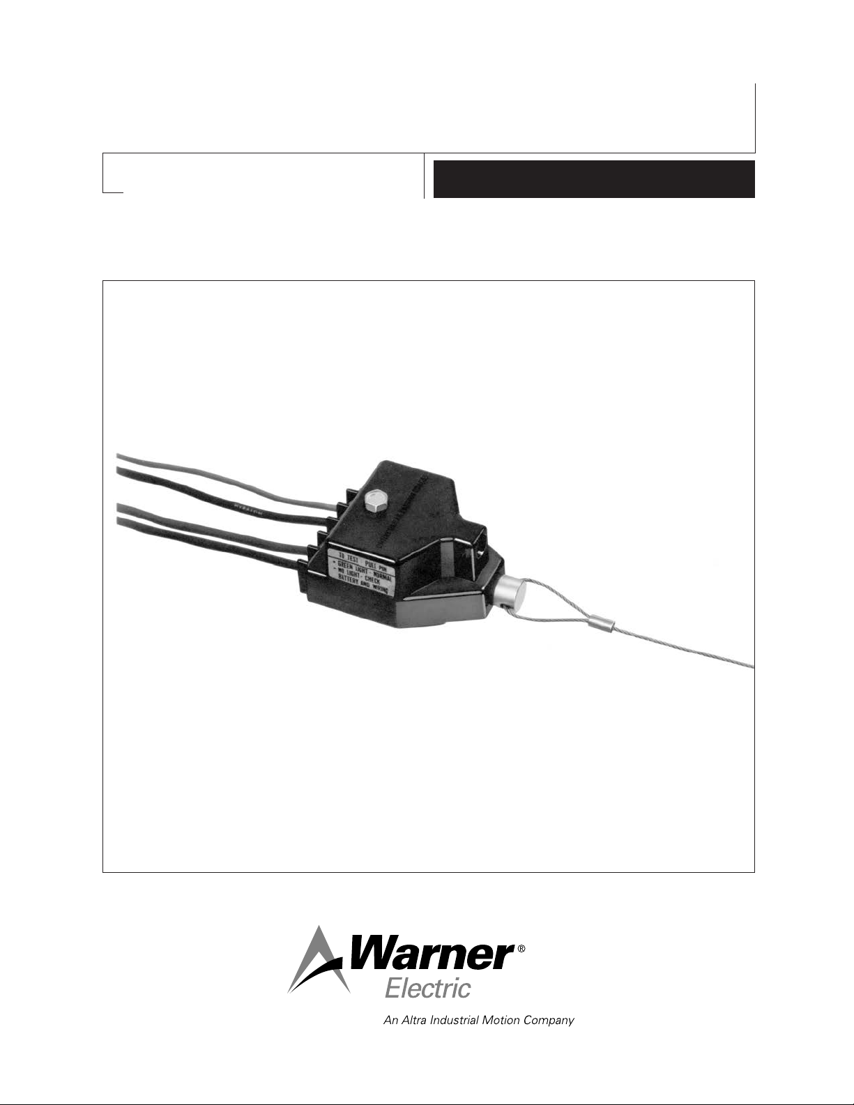
Safety Sentry
™
Electronic Breakaway Switch
P-616
819-0454
Installation Instructions
Page 2
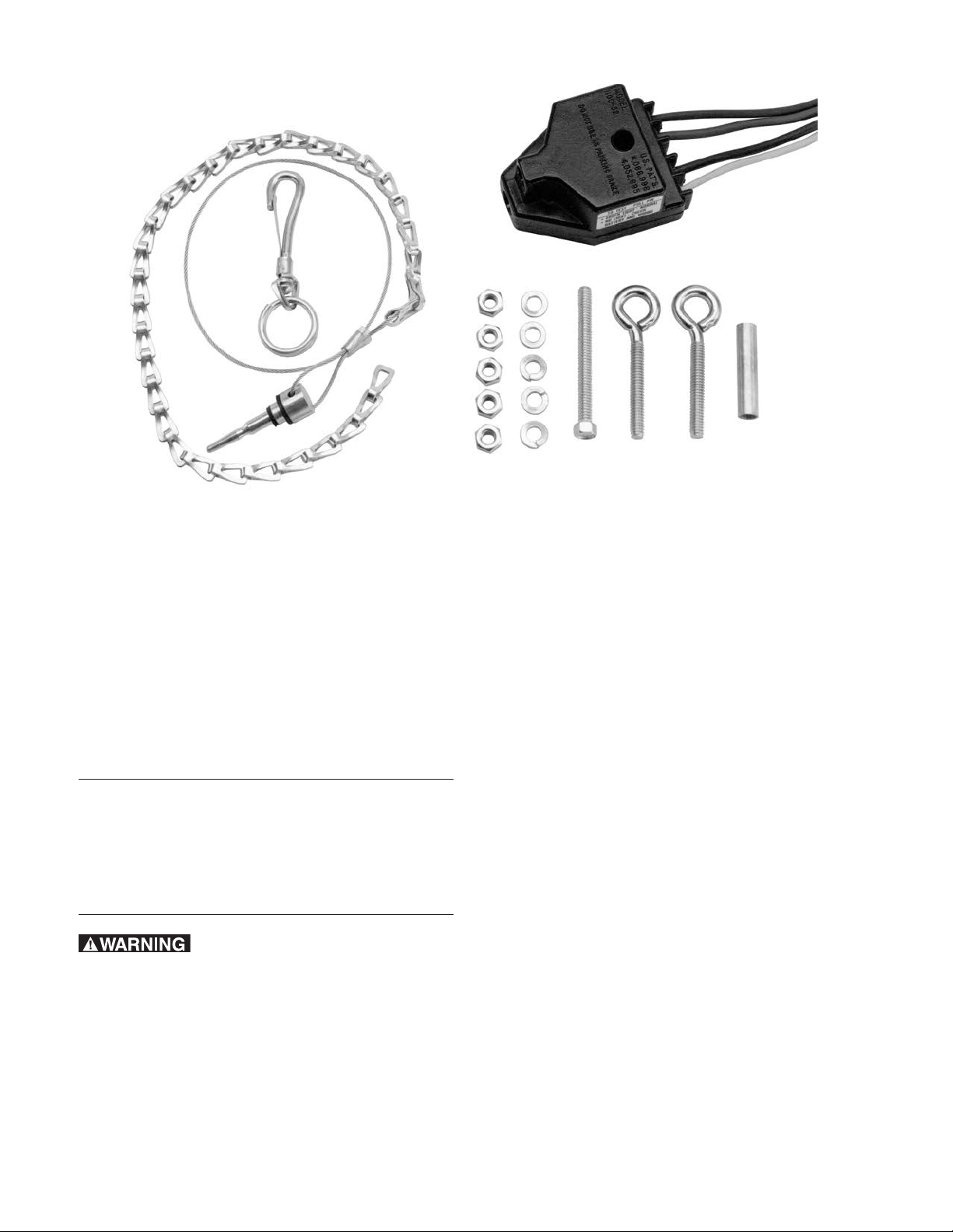
Parts List
Introduction
Mounting hardware included with the Safety Sentry
Breakaway Switch kit:
Qty Part
1 Chain/lanyard with snap hook
1 2-1/2" Bolt
1 1-5/8" Sleeve
2 Eyebolts
5 Lockwashers
5 Nuts
Failure to follow these
instructions may result in product damage,
equipment damage, and fatal injury to
personnel.
The main purpose of any trailer breakaway switch is
to automatically engage the electric trailer brakes
should the trailer become detached from the towing
vehicle. In addition to this basic function, your Safety
Sentry Breakaway Switch will:
1. Test the battery under load for approximately 10
volts minimum.
2. Illuminate its green light to indicate that the trailer
battery and breakaway switch are
operating properly.
Warner Electric • 800-825-9050 P-616 • 819-0454
2
Page 3
Mounting
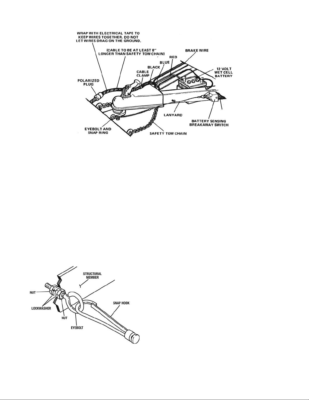
Figure 1 - Typical Layout
Note the general layout in Figure 1 as you proceed
through the mounting instructions. Refer to the
parts list, page 2.
1. Drill a 9/32-inch hole for an eyebolt in a
convenient structural member on your towing
vehicle chassis near the hitch (not on the hitch
assembly).
Mount the eyebolt, with the eyebolt pointing
toward the breakaway switch, using two
1/4-inch nuts with lockwashers. Tighten
securely. See Figure 2.
2. Position the breakaway switch on a horizontal
or vertical surface of the trailer tongue or Aframe. The pin in the switch must point
towards the towing vehicle.
The switch must be positioned far enough
forward so the lanyard will reach the towing
vehicle.
It must also be set back far enough to allow an
eyebolt to be mounted to the tongue in front of
the switch.
3. Drill a 9/32-inch hole through the tongue for
mounting the switch.
Insert the furnished metal sleeve into the
mounting hole in the switch. The sleeve allows
the switch to pivot so the lanyard stays aligned
with the towing vehicle.
Bolt the switch to the tongue using the bolt,
nut, and lockwasher provided.
Figure 2
Towing Vehicle Eyebolt Mounting
Warner Electric • 800-825-9050 P-616 • 819-0454
3
Page 4

Figure 3 - Trailer Tongue Eyebolt Mounting
4. Refer to Figure 3 for correct location for
mounting the second eyebolt.
Drill a 9/32-inch hole for the eyebolt. Secure
with two 1/4-inch nuts and two lockwashers.
This eyebolt is necessary so that the pin will be
pulled straight out from the breakaway switch
if the trailer should become disconnected.
5. Insert the breakaway switch disengagement
pin into the breakaway switch.
6. Disconnect the snap hook (it is not
permanently attached) from the chain end of
the lanyard assembly. Save the hook and its
attachment clip.
7. Thread the lanyard, chain end first, through the
eyebolt mounted on the trailer tongue.
8. Determine the correct length for the lanyard.
The lanyard is the correct length if the following
conditions are satisfied:
Condition 1: If trailer should become
disconnected, the lanyard must become
taut and pull the pin out of the breakaway
switch before the trailer safety chains
become taut.
Condition 2: If the trailer should become
disconnected, the lanyard must become taut
and pull the pin out of the breakaway switch
before the towing vehicle-to-trailer electrical
wiring becomes taut. Making the electrical
wires longer than the safety chains is a
convenient way to accomplish this.
Condition 3: During normal towing operation,
the lanyard must NOT become taut enough to
pull the pin out of the breakaway switch when
turning a corner.
Condition 4: During normal towing operation,
either straight or while turning corners, no
chains or wiring should be allowed to drag on
the ground.
Adjust the lanyard to the right length by
removing the individual chain links.
The lanyard, if installed correctly, now extends
from the switch, with the pin inserted into the
switch, through the eyebolt on the trailer
tongue, and attaches to the eyebolt on the
towing vehicle.
9. Leaving the lanyard threaded through the
eyebolt on the trailer tongue, secure the snap
hook to the end chain link. Use pliers to close
the snap hook attachment clip completely
around the end of the snap hook.
10. Fasten snap hook to the towing vehicle
eyebolt.
Warner Electric • 800-825-9050 P-616 • 819-0454
4
Page 5

Electrical Connection
Recommended Parts List for Customer Wiring:
Item Qty Description
1. 6' No. 12 AWG insulated wire (stranded) blue
2. 6' No. 12 AWG insulated wire (stranded) black
3. 6' No. 12 AWG insulated wire (stranded) white
4. 6' No. 12 AWG insulated wire (stranded) red
5. 2 1/4-inch bolts, length suitable for the type of trailer tongue used
6. 2 1/4-inch nuts
7. 4 washers for 1/4-inch bolt
8. 2 lockwashers for 1/4-inch bolt
9. 1 roll of electrical tape
10. 3 wire nuts or insulated line connectors (binding screw type) for three No. 12 AWG wires
11. 1 socket and plug connector with a minimum of three poles capable of accepting
No. 12 AWG wire
12. 1 12 volt wet cell battery (100 amp-hour max.)
Figure 4 - Wiring Diagram
Refer to the wiring diagram shown in Figure 4 as
you follow the electrical connection instructions
wet cell storage battery with a maximum rated
capacity of 100 amp-hours.
below. Plan ahead by starting with long wires. All
wires must be a least No. 12 AWG and insulated.
The final length of the wires from the trailer,
including the connector, should be longer than
the safety chains.
Solder connections are preferable for attaching
two wires together. If crimp-type connectors are
used, make sure they are crimped tightly. All such
connections should be taped with electrical tape
to prevent corrosion and short circuiting.
(Note: Refer to Mounting, Item 8, Condition 2).
The trailer battery must be 12 volts and have
adequate capacity to meet all legal requirements of
the state in which the trailer will be towed. Use a
Warner Electric • 800-825-9050 P-616 • 819-0454
5
Page 6

Your breakaway switch has four wires: white, blue,
black, and red. They should be connected as
follows:
1. Ground – White Wire
Attach the white wire to the trailer frame
adjacent to the switch using a 1/4-inch bolt,
nut, two washers, and one lockwasher. Be
sure the frame area is bare metal and free of
rust. (See Figure 5)
Figure 5 - Ground Connections
2. Brakes – Blue Wire
Connect the blue wire to the positive (+) wire
running to the trailer brakes. Be careful not to
connect to the ground (-) wire leading from the
brakes.
3. Trailer Battery Charging – Black Wire
Warner Electric recommends that a charging
circuit be used to maintain the trailer battery in
a fully-charged condition.
a. If a charging circuit is used, it must be
connected through the Safety Sentry switch
using the black wire as shown in Figure 4.
Connect the black wire from the switch,
through the polarized connector, to the output
side of the battery isolator. If a battery isolator
is not used, connect the wire directly to the
towing vehicle battery (+) terminal.
The wire must be long enough for the switch
to swivel freely after the connection to the
trailer frame has been made. Make sure the
final connection is tight.
Connect the trailer battery ground (-) to the
trailer frame, also using 1/4-inch bolt, nut, two
washers, and one lockwasher as shown in
Figure 5.
Make sure the final connection is tight. (Note:
The white wire from the switch and the battery
ground terminal may be connected to one
common ground on the trailer frame if
convenient.)
A ground wire should be run from the towing
vehicle battery (-) to the socket at the rear of
the vehicle. From the socket, the ground wire
should be connected to the trailer frame.
(There should now be a total of 3 ground
connections: the breakaway switch white wire
to the trailer frame; the ground side of the
trailer battery to the trailer frame; the ground
side of the towing vehicle battery, through the
socket at the rear of the vehicle, to the trailer
frame.)
Failure to connect the
charging circuit through the switch will
result in incorrect operation of the switch.
b. If a charging circuit is not used, cut off the
black wire from the Safety Sentry close to the
switch's plastic housing. Insulate the exposed
end of the wire with a recognized electrical
insulating tape or equivalent. This will prevent
the exposed lead from grounding.
Failure to cut off and
insulate the black wire when no charging
circuit is used could cause an electrical
short circuit. This may deplete the trailer
battery and destroy the Safety Sentry,
completely immobilizing the breakaway
system.
4. Trailer Battery – Red Wire
Connect the red wire directly to the trailer
battery (+) terminal using an appropriate
battery connector.
Warner Electric • 800-825-9050 P-616 • 819-0454
6
Page 7

Operation
Your Safety Sentry Breakaway Switch should now
be ready for use. Always test the system before
using it to assure that it is in proper working
condition.
Use the following procedure to test the brake
system:
1. Put the towing vehicle in “Park”. Set the
emergency brake if the vehicle has manual
transmission.
2. Couple the plug and socket together.
The battery will be charged directly from the
towing vehicle while the engine is running. To
accomplish this the pin must be inserted in the
switch.
If the battery does not charge to 10 volts, it
must be replaced.
The green light should now illuminate, or the
trailer brakes must be checked.
c. Check the trailer brake wiring. All brake
magnets should be connected with good
quality connectors and taped to avoid a
possible short circuit.
3. Pull the disengagement pin from the switch.
The green light on the switch will illuminate for
at least 10 seconds if the system is connected
and the battery is functioning properly.
4. If the green light does not illuminate, use the
following procedure to check the system and
locate the cause of the problem:
a. Check your wiring to ensure all connections
have been made properly. Refer to Figure 4.
Check all connections to be sure they are
tight. Check ground connections to be sure
they are attached to rust-free areas of the
trailer frame. They must be connected to bare
metal surfaces.
Correct any errors which have been made. If
the green light does not illuminate, proceed
with the next step.
b. Use a voltmeter to check the trailer battery for
proper output. The battery must supply at
least 10 volts, with the switch pin pulled (trailer
brakes on), for the green light to illuminate.
d. The green light should now illuminate, or the
Safety Sentry should be replaced.
e. As a final check, pull the disengagement pin
on the Safety Sentry and try to pull the trailer
forward with the towing vehicle. If the trailer
brakes are engaged, it will be difficult for the
towing vehicle to move the trailer.
If the trailer and towing vehicle
are connected while parked, prolonged use
of the trailer battery for lights or other
purposes will also drain the towing vehicle
battery. The problem can be avoided by
disconnecting the plug from the socket.
DO NOT USE AS A PARKING BRAKE (pin
removed). Prolonged activation will discharge
the battery and cause the brakes to release.
If the voltage is low, the battery should be
charged to a minimum of 10 volts and
checked again with the pin pulled before the
trailer is towed.
Warner Electric • 800-825-9050 P-616 • 819-0454
7
Page 8

Warranty
Warner Electric LLC warrants that it will repair or replace (whichever it deems advisable) any
product manufactured and sold by it which proves to be defective in material or workmanship within
a period of one (1) year from the date of original purchase for consumer, commercial or industrial
use.
This warranty extends only to the original purchaser and is not transferable or assignable without
Warner Electric LLC’s prior consent.
Warranty service can be obtained in the U.S.A. by returning any defective product, transportation
charges prepaid, to the appropriate Warner Electric LLC factory. Additional warranty information may
be obtained by writing the Customer Satisfaction Department, Warner Electric LLC, 449 Gardner
Street, South Beloit, Illinois 61080, or by calling 815-389-3771.
A purchase receipt or other proof of original purchase will be required before warranty service is
rendered. If found defective under the terms of this warranty, repair or replacement will be made,
without charge, together with a refund for transportation costs. If found not to be defective, you will
be notified and, with your consent, the item will be repaired or replaced and returned to you at your
expense.
This warranty covers normal use and does not cover damage or defect which results from
alteration, accident, neglect, or improper installation, operation, or maintenance.
Some states do not allow limitation on how long an implied warranty lasts, so the above limitation
may not apply to you.
Warner Electric LLC’s obligation under this warranty is limited to the repair or replacement of the
defective product and in no event shall Warner Electric LLC be liable for consequential, indirect,
or incidental damages of any kind incurred by reason of the manufacture, sale or use of any
defective product. Warner Electric LLC neither assumes nor authorizes any other person to give
any other warranty or to assume any other obligation or liability on its behalf.
WITH RESPECT TO CONSUMER USE OF THE PRODUCT, ANY IMPLIED WARRANTIES WHICH
THE CONSUMER MAY HAVE ARE LIMITED IN DURATION TO ONE YEAR FROM THE DATE OF
ORIGINAL CONSUMER PURCHASE. WITH RESPECT TO COMMERCIAL AND INDUSTRIAL
USES OF THE PRODUCT, THE FOREGOING WARRANTY IS IN LIEU OF AND EXCLUDES ALL
OTHER WARRANTIES, WHETHER EXPRESSED OR IMPLIED BY OPERATION OF LAW OR
OTHERWISE, INCLUDING, BUT NOT LIMITED TO, ANY IMPLIED WARRANTIES OF
MERCHANTABILITY OR FITNESS.
Some states do not allow the exclusion or limitation of incidental or consequential damages, so the
above limitation or exclusion may not apply to you. This warranty gives you specific legal rights and
you may also have other rights which vary from state to state.
Changes in Dimensions and Specifications
All dimensions and specifications shown in Warner Electric catalogs are subject to change without
notice. Weights do not include weight of boxing for shipment. Certified prints will be furnished
without charge on request to Warner Electric.
Warner Electric LLC
31 Industrial Park Road • New Hartford, CT 06057
815-389-3771 • Fax: 815-389-2582
www.warnerelectric.com
P-616 • 819-0454 8/11 Printed in USA
An Altra Industrial Motion C ompany
 Loading...