

Page 1

Pump Clutch Installation
P-1423
819-0388
Installation Instructions
Page 2
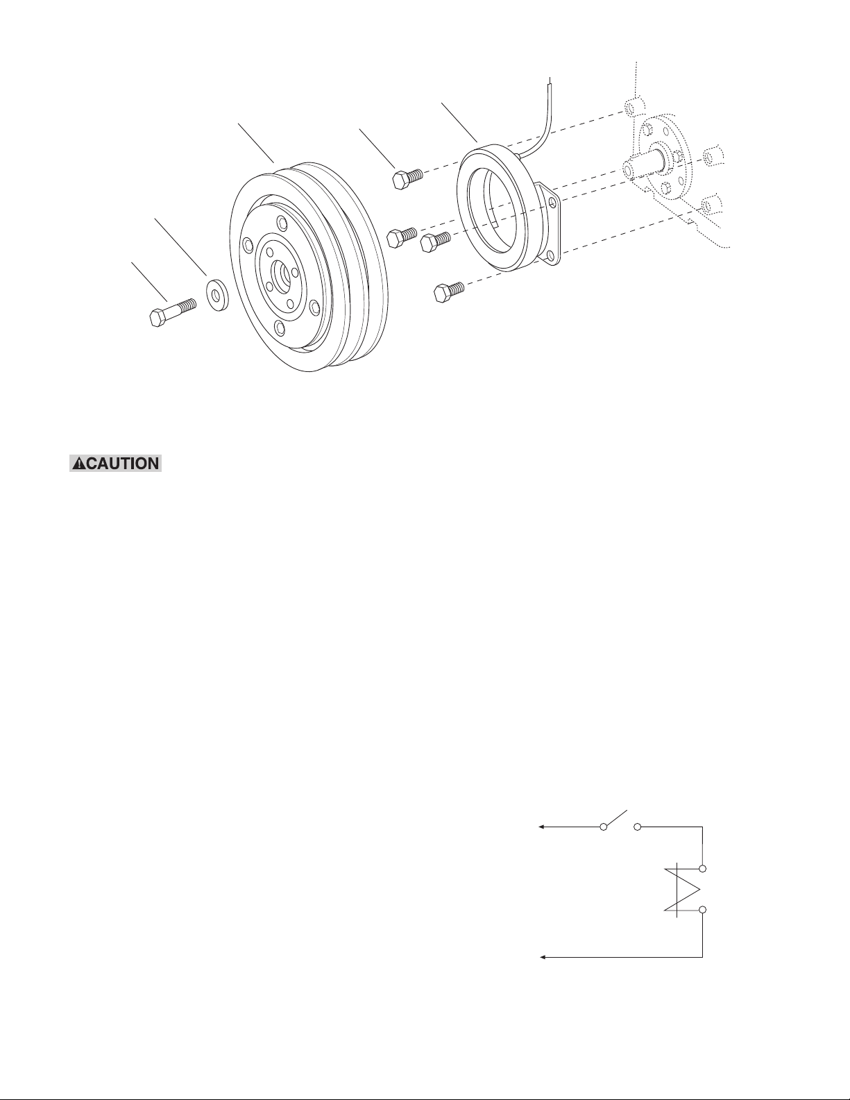
Washer (4)
Rotor-Pulley
Assembly (3)
Capscrews &
Lockwashers (2)
Field Assembly (1)
Cap Screw (5)
Rotor-Pulley
Assembly
Failure to follow these
instructions may result in product damage,
equipment damage, and serious or fatal
injury to personnel.
General
This pump clutch has been developed specifically
for use in pump applications. Properly installed, it
will provide maintenance-free service. The clutch
uses a stationary field that does not require slip
rings or brushes.
The clutch consists of two major components;
a stationary magnetic field assembly and a
rotor-pulley assembly. The field assembly is
mounted on the pump face. The rotor-pulley is
mounted to the pump shaft and driven by v-belts.
Electricity energizes the clutch field to couple the
clutch magnetically, thus driving the pump
mechanism. De-energizing the field releases
the clutch and uncouples the pump.
Pump
(Not Included)
Field
Assembly
Wiring
The coil in the field assembly has a single leadwire
(hot) and is grounded through the field shell. It will
only be necessary to connect this leadwire to the
electrical system as the pump should already be
negatively grounded. Figure 1 shows an example
of a typical system.
Service
The clutch automatically compensates for wear
requiring no adjustments throughout the life of the
clutch. Do not lubricate the unit. If the clutch
should fail to operate, check the electrical circuit to
be sure the proper voltage is being supplied to the
clutch. Do not attempt to make any mechanical
adjustments to the clutch.
Clutch Switch
Positive
Clutch
Negative
Figure 1
Warner Electric • 800-825-9050 P-1423 • 819-0388
2
Page 3

Installation
Diagnose Clutch Failure
Most clutch failures are a direct result of a system
problem or failure. Before installing a new clutch,
determine what caused the old clutch to fail and
fix the system problem. By simply replacing the
clutch without fixing the cause of the clutch
failure, the new clutch may fail in the same
manner as the old clutch.
Step 1
Position the field assembly (1) against the face of
the pump and align the field mounting holes with
those in the pump. Insert four capscrews into the
bolt holes. Tighten the capscrews to a wrench
torque of 7-10 lb.ft. (85-120 lb.in.).
Use care not to strip the
threads in the pump body.
Step 2
The pump shaft must be clean and free of burrs.
Check the shaft key for proper position and
seating.
Step 3
Slide the rotor-pulley assembly (3) onto the
tapered shaft (aligning the key and the keyway).
Secure the rotor-pulley assembly using the
washer (4) and self-locking capscrew (5) provided
with the clutch. Tighten the capscrew to a wrench
torque of 15-20 lb.ft. (180-240 lb.in.)
Step 5 (If Required)
To remove the rotor-pulley from the pump shaft,
remove the self-locking capscrew (5) and washer
(4). Then, insert a 5/8-11 UNC capscrew (not
provided) into the center hole of the rotor. Rotate
the screw against the pump shaft until the rotor
breaks loose from the shaft.
Do not use a wheel puller on
theouter diameter of the pulley as this can
damage the clutch bearing. Warranty will be
voided if clutch is removed without using the
5/8-11 UNC threaded hole provided in the hub
center.
Step 6
Clutch Burnish Procedure
Install drive belts as required by pump design. Run
the pump at normal operating speed and cycle the
clutch on and off at a rate of 10 to 15 times per
minute for 50 cycles minimum. This procedure will
help bring the clutch up to operating torque
capacity.
Note: To prevent electrical system damage,
use the pump clutch control to cycle the
clutch.
Step 4
Rotate the rotor-pulley manually to ensure there
is no interference between the field and the
rotor-pulley. If any interference occurs, a
rubbing/scrapping noise will be heard as the
pulley rotates. If rubbing or some other
mechanical interference does occur, disassemble
the clutch (per step 5) and repeat assembly
of the field assembly to the pump.
Warner Electric • 800-825-9050 P-1423 • 819-0388
3
Page 4

Warranty
Warner Electric LLC warrants that it will repair or replace (whichever it deems advisable) any
product manufactured and sold by it which proves to be defective in material or workmanship within a
period of one (1) year from the date of original purchase for consumer, commercial or industrial use.
This warranty extends only to the original purchaser and is not transferable or assignable without Warner
Electric LLC’s prior consent.
Warranty service can be obtained in the U.S.A. by returning any defective product, transportation
charges prepaid, to the appropriate Warner Electric LLC factory. Additional warranty information may be
obtained by writing the Customer Satisfaction Department, Warner Electric LLC, 449 Gardner Street,
South Beloit, Illinois 61080, or by calling 815-389-3771.
A purchase receipt or other proof of original purchase will be required before warranty service is
rendered. If found defective under the terms of this warranty, repair or replacement will be made, without
charge, together with a refund for transportation costs. If found not to be defective, you will be notified
and, with your consent, the item will be repaired or replaced and returned to you at your expense.
This warranty covers normal use and does not cover damage or defect which results from
alteration, accident, neglect, or improper installation, operation, or maintenance.
Some states do not allow limitation on how long an implied warranty lasts, so the above limitation may
not apply to you.
Warner Electric LLC’s obligation under this warranty is limited to the repair or replacement of the
defective product and in no event shall Warner Electric LLC be liable for consequential, indirect,
or incidental damages of any kind incurred by reason of the manufacture, sale or use of any defective
product. Warner Electric LLC neither assumes nor authorizes any other person to give any other
warranty or to assume any other obligation or liability on its behalf.
WITH RESPECT TO CONSUMER USE OF THE PRODUCT, ANY IMPLIED WARRANTIES WHICH THE
CONSUMER MAY HAVE ARE LIMITED IN DURATION TO ONE YEAR FROM THE DATE OF ORIGINAL
CONSUMER PURCHASE. WITH RESPECT TO COMMERCIAL AND INDUSTRIAL USES OF THE
PRODUCT, THE FOREGOING WARRANTY IS IN LIEU OF AND EXCLUDES ALL OTHER WARRANTIES,
WHETHER EXPRESSED OR IMPLIED BY OPERATION OF LAW OR OTHERWISE, INCLUDING, BUT
NOT LIMITED TO, ANY IMPLIED WARRANTIES OF MERCHANTABILITY OR FITNESS.
Some states do not allow the exclusion or limitation of incidental or consequential damages, so the
above limitation or exclusion may not apply to you. This warranty gives you specific legal rights and you
may also have other rights which vary from state to state.
Changes in Dimensions and Specifications
All dimensions and specifications shown in Warner Electric catalogs are subject to change without
notice. Weights do not include weight of boxing for shipment. Certified prints will be furnished without
charge on request to Warner Electric.
Warner Electric LLC
31 Industrial Park Road • New Hartford, CT 06057
815-389-3771 • Fax: 815-389-2582
www.warnerelectric.com
P-1423 • 819-0388 8/11 Printed in USA
An Altra Industrial Motion C ompany
 Loading...