

Page 1
Preassembled Clutch/Brake Module
P-273-1
819-0343
Installation Instructions
Page 2
2
Warner Electric • 800-825-9050 819-0343
Contents
Mounting to a Motor . . . . . . . . . . . . . . .3
Mounting to a Reducer . . . . . . . . . . . . .3
Installing the Base Mount . . . . . . . . . . .4
Installing the Motor Mount . . . . . . . . . . .4
Electrical Connections . . . . . . . . . . . . . .4
Start Up . . . . . . . . . . . . . . . . . . . . . . . . .5
Troubleshooting . . . . . . . . . . . . . . . . . . .5
Electrical Coil Data . . . . . . . . . . . . . . . .6
Mechanical Data . . . . . . . . . . . . . . . . . .6
Warranty . . . . . . . . . . . . . . . . .Back page
Failure to follow these
instructions may result in product damage,
equipment damage, and serious or fatal
injury to personnel.
Warner Electric’s UniModule has been designed
to NEMA standards and can be installed with all
standard power transmission drive systems.
Before installing the UniModule to a motor or
reducer, make certain that the UM UniModule
size and NEMA frame dimensions match according to the following chart.
Corresponding
NEMA Frame Sizes
C-Face
UM Old New Shaft Pilot
Size NEMA NEMA Dia. Dia.
50 56 C 48 Y 5/8 4 1/2
100 56 C 48 Y 5/8 4 1/2
180 182 C 143 TC 7/8 4 1/2
184 C 145 TC
210 213 C 182 TC 1-1/8 8 1/2
215 C 184 TC
215 213TC 1 3/8 8 1/2
215 TC 1 3/8 8 1/2
Install your specific modular combination according to the installation steps specified in the table.
Use only those steps indicated for each combination.
The 1020 and 1040 UniModules are furnished
with a special hardened key. It is strongly recommended that this key be used with the motor
shaft to avoid damage to the shaft and rotor hub.
The size 210 UniModules require an adapter ring
to be mounted to the motor prior to mounting the
1020 or 1040 UniModule. Adapter and mounting
hardware are provided with the UniModule
assembly.
Note: The equipment covered by this service
manual must be installed in accordance with
these instructions. Failure to do so may damage the equipment and void the warranty.
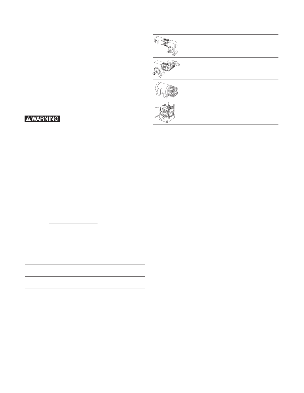
For These UM Combinations Use These
Installation Steps:
UniModule Clutch/Brake Between Mounting to a Motor
C-Face Motor and Reducer - 1020 Mounting to a Reducer
UniModule Clutch between Electrical Connections
Motor and Reducer - 1040 Start Up
UniModule Clutch/Brake - 2030 Chain or pulley Drive to
a Reducer
Electrical Connection
UniModule Clutch - 3040 Start Up
Motor Mount Module Clutch-Brake Mounting to a Motor
on a C-Face Motor - 1020-M Installing the Motor Mount
Motor Mount UniModule Clutch Electrical Connection
on a C-Face Motor - 1040-M Start Up
Base Mounted Installing the Base Mount
UniModule Clutch-Brake - 2030-B Electrical Connection
UniModule Clutch - 3040-B Start Up
Page 3

3
Warner Electric • 800-825-9050 819-0343
3. The access hole for the Allen wrench to tighten the rotor setscrews is shown in Figure 3.
Rotate the clutch rotor as necessary to insert
the wrench into the setscrews. Tighten both
screws alternately and securely. Failure to
properly tighten the setscrews may result in
damage to the motor shaft and rotor hub and
will void warranty. (40 to 45 in. lbs. for 180
size, 80 to 85 in. lbs. for 50 and 210 sizes.)
Figure 3
Mounting to a Reducer
The output side of a UniModule may be
mounted directly to a reducer.
A. Align the output shaft and key of the
UniModule with the corresponding shaft hole
and keyway of the reducer. Slide assembly
together, matching pilot diameter on the
UniModule with pilot diameter on the reducer.
B. Bolt the UniModule to the reducer flange. The
four (4) bolts required (3/8 - 16 UNC-2A) are
normally furnished with the reducer. (18 to 22
ft. lbs. for 50 and 180 sizes, 40 to 45 lbs. for
210 size.)
Figure 4
Mounting to a Motor:
1. Replace the existing motor shaft key with the
hardened key provided with the unit. If necessary, prick punch the keyway of the motor
shaft to keep the key from moving in the keyway. Slide the module assembly onto the
motor shaft. (See Figure 1) Align the key in
the motor shaft with the keyway in the rotor
hub.
Do not use force. If the UniModule does
not slide on freely, polish the motor shaft
sufficiently to achieve a slip fit.
Figure 1
2. The housing is provided with vent holes which
are normally placed in the down position.
Rotate the assembly to where the vent holes
are toward the bottom and insert the four long
capscrews (provided) through the mounting
holes in the housing and into the motor face.
Tighten alternately and securely. (30 to 35 ft.
lbs.)
Figure 2
Page 4

4
Warner Electric • 800-825-9050 819-0343
Size 210
A. Mount the UniModule on the Motor Mount so
that the base of the Motor Mount is underneath the UniModule and motor (Figure 6). A
pilot diameter on the UniModule mates with a
pilot diameter on the Motor Mount.
B. Secure the Motor Mount to the UniModule
with three (3) bolts provided. (40 to 45 ft. lbs.)
Figure 6
Electrical Connections
To avoid injury (or even
death), always make certain all power is off
before attempting to install or service this
control or any electrical equipment.
The UniModule is provided with one conduit connection hole, threaded for standard 1/2" conduit
connectors. Both the clutch and the brake lead
wires are brought out through this opening. The
conduit box accessory kit, P/N 5370-101-042,
provides two conduit connection holes for standard 1/2" conduit connectors.
The clutch and brake coils operate on DC voltage. Warner Electric offers a full line of AC voltage powered controls to meet the needs of
almost every clutch/brake application. The service and installation instructions included with
each Warner Electric control show the proper
electrical connections.
Installing the Base Mount
UniModules 2030 and 3040 can be basemounted. (Figure 5)
Figure 5
A. Mount each UniModule so that the base is
located below the ventilation holes. A pilot
diameter on the end of each UniModule
mates with pilot diameters on the base.
B. Secure the base to the UniModule with the
four (4) bolts provided. (18 to 22 ft. lbs. for 50
and 180 sizes, 40 to 45 ft. lbs. for 210 size.)
Installing the Motor Mount (M)
A. Motor Mount (M) can be installed to the out-
put end of the UniModule to provide a foot
mounting for the complete assembly of
UniModule and motor.
Size 50, 100, and 180
A. Remove the two (2) long hex head bolts from
the side of the UniModule toward the ventilation holes.
B. Mount the UniModule on the Motor Mount so
that the base of the Motor Mount is underneath the UniModule and motor (Figure 6). A
pilot diameter on the UniModule mates with a
pilot diameter on the Motor Mount.
C. Secure the Motor Mount in place with two (2)
longer mounting bolts (30 to 35 ft lbs.) and
the two shorter bolts (18 to 22 ft. lbs.) all provided in the kit.
Page 5
5
Warner Electric • 800-825-9050 819-0343
Trouble Shooting - Mechanical
A likely mechanical cause for a clutch or brake
not engaging when DC power is applied is that
the airgap between the friction faces is too
large. When power is applied to an Electro-magnetic clutch/brake, the unit magnetically clamps
the friction faces together.
An airgap that is too large can keep the unit
from clamping together. Sometimes this airgap,
when set at the factory can shift during shipment or installation.
To r eset the airgap, you will need to access the
armatures. There are gaps between the fins on
the housing on 1/3 of the unit circumference.
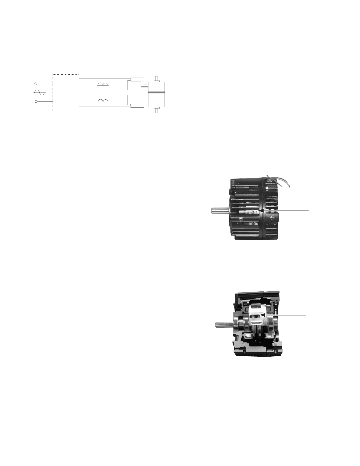
Figure 7
When looking through one of these gaps, you
will see the fan on the clutch rotor. In that fan,
there is a 1/2" x 1" window.
Figure 8
It is possible to look inside the unit and see the
armatures by looking through this window.
When looking into the window, you will be looking between the two armatures of a clutch/brake
unit.
Clutch/Brake
Control
AC
Clutch
Brake
White
Black
Red
Red
Black
Black
DC
DC
Vol ta ge
Voltage
Voltage
Start-Up
With the motor at rest, check the following:
A. Spin the output shaft by hand to ensure that
it turns freely. The bearings should be quiet
and the armatures should not drag.
B. With full voltage applied to the clutch or
brake, switch back and forth between the
clutch and brake and observe the armatures
(plates) through the vent holes and opening in
the fan. They should move back and forth
approximately 1/32" when switched. Turn
the output shaft as you check to be sure that
the armatures fully engage 360 degrees.
Trouble Shooting - Electrical
If a clutch or brake or clutch/brake will not
engage, review wiring, switching, and connections.
1. Using a multimeter, confirm that DC voltage is
reaching the lead wires when it should be
and that the coil resistance is correct. (See
Electrical Coil Data)
2. Visually inspect to ensure that the lead wires
are not split or cut.
Please refer to the following figure for the proper
UniModule electrical connections. Clutch leads
are identified with a white insulator sleeve.
Brake leads have a black insulator sleeve.
Page 6

6
Warner Electric • 800-825-9050 819-0343
Figure 9
If the armature for either the clutch or the
brake is too far away from its mating friction
surface, it is possible to move this back into
adjustment using a flat head screwdriver.
This is a three-step process.
1. Simply slide the screwdriver through the
window and press the armature toward its
mating friction surface.
2. Rotate the output of the unit. The rotor
and window should stay in place when you
do this. Only the armatures will move.
Rotating the rotor will move the window.
3. Repeat steps 1 & 2 to ensure that the airgap between the armature and its mating
friction surface is about 1/32" and that the
armature is kept square. (If the armature is
cocked, it may engage on one rim, giving
the appearance of engagement but failing
to provide full torque.)
If a scraping sound is noted when the output
shaft is spun, it means an armature is dragging. Insert a screwdriver through the vent
holes and slot in the fan and pry the dragging
armature (clutch or brake as observed) away
from the mating surface evenly all the way
around. Re-check the engagement as
described in step B of the Start-Up instructions.
Electrical Coil Data
Clutch Brake Clutch Brake Clutch Brake
Voltage–D.C. 90 90 24 24 6 6
Resistance UM-50 452 452 31.8 31.8 1.86 1.86
(OHMS) UM-100/180 392 392 26.7 26.7 1.81 1.81
UM-210/215 248 248 17.9 17.9 1.22 1.22
Amperes UM-50 .199 .201 .755 .755 3.23 3.23
UM-100/180 .230 .230 .896 .896 3.31 3.31
UM-210/215 .363 .363 1.34 1.34 4.9 4.9
WATTS (17.9) UM-50 18 18 18.1 18.1 19.4 19.4
UM-100/180 20.7 20.7 21.5 21.5 20.0 20.0
UM-210/215 32.7 32.7 32 32 29.6 29.6
Build Up UM-50 52 53 52 53 52 53
(Milliseconds) UM-100/180 72 75 72 75 72 70
UM-210/215 120 100 120 100 110 100
Decay UM-50 6.2 5.0 6.2 5.0 6.5 5.0
(Milliseconds) UM-100/180 12 10 12 10 12 10
UM-210/215 20 10 20 10 20 10
Mechanical Data
UM-50 UM-100/180 UM-210/215
Static Torque - lb. ft. 16 30 95
Maximum Speed - rpm 3600 3600 3600
Average Weight-lbs.
1020 10 13.2 30.6/31
1040 8.3 10.3 24.3/25
2030 13 16.5 41.3/42
3040 11.3 13.6 35/35.5
Inertia - WR - lb.ft.
Configuration 50 100/180 210 215
1020 input .021 .047 .190 .190
1020 output .0195 .050 .193 .195
1040 input .021 .047 .190 .190
1040 output .0105 .027 .112 .114
2030 input .021 .048 .198 .200
2030 output .0195 .050 .193 .195
3040 input .021 .048 .198 .200
3040 output .0105 .027 .112 .114
Page 7

7
Warner Electric • 800-825-9050 819-0343
Page 8

Warranty
Warner Electric LLC warrants that it will repair or replace (whichever it deems advisable) any
product manufactured and sold by it which proves to be defective in material or workmanship
within a period of one (1) year from the date of original purchase for consumer, commercial or
industrial use.
This warranty extends only to the original purchaser and is not transferable or assignable without
Warner Electric LLC’s prior consent.
Warranty service can be obtained in the U.S.A. by returning any defective product, transportation
charges prepaid, to the appropriate Warner Electric LLC factory. Additional warranty information
may be obtained by writing the Customer Satisfaction Department, Warner Electric LLC, 449
Gardner Street, South Beloit, Illinois 61080, or by calling 815-389-3771.
A purchase receipt or other proof of original purchase will be required before warranty service is
rendered. If found defective under the terms of this warranty, repair or replacement will be made,
without charge, together with a refund for transportation costs. If found not to be defective, you
will be notified and, with your consent, the item will be repaired or replaced and returned to you
at your expense.
This warranty covers normal use and does not cover damage or defect which results from
alteration, accident, neglect, or improper installation, operation, or maintenance.
Some states do not allow limitation on how long an implied warranty lasts, so the above limitation
may not apply to you.
Warner Electric LLC’s obligation under this warranty is limited to the repair or replacement of the
defective product and in no event shall Warner Electric LLC be liable for consequential, indirect,
or incidental damages of any kind incurred by reason of the manufacture, sale or use of any
defective product. Warner Electric LLC neither assumes nor authorizes any other person to give
any other warranty or to assume any other obligation or liability on its behalf.
WITH RESPECT TO CONSUMER USE OF THE PRODUCT, ANY IMPLIED WARRANTIES WHICH
THE CONSUMER MAY HAVE ARE LIMITED IN DURATION TO ONE YEAR FROM THE DATE OF
ORIGINAL CONSUMER PURCHASE. WITH RESPECT TO COMMERCIAL AND INDUSTRIAL
USES OF THE PRODUCT, THE FOREGOING WARRANTY IS IN LIEU OF AND EXCLUDES ALL
OTHER WARRANTIES, WHETHER EXPRESSED OR IMPLIED BY OPERATION OF LAW OR
OTHERWISE, INCLUDING, BUT NOT LIMITED TO, ANY IMPLIED WARRANTIES OF
MERCHANTABILITY OR FITNESS.
Some states do not allow the exclusion or limitation of incidental or consequential damages, so
the above limitation or exclusion may not apply to you. This warranty gives you specific legal
rights and you may also have other rights which vary from state to state.
Changes in Dimensions and Specifications
All dimensions and specifications shown in Warner Electric catalogs are subject to change without
notice. Weights do not include weight of boxing for shipment. Certified prints will be furnished
without charge on request to Warner Electric.
Warner Electric LLC
449 Gardner Street
• South Beloit, IL 61080
815-389-3771
• Fax: 815-389-2582
www.warnerelectric.com
P-273-1 819-0343 6/05 Printed in USA
 Loading...