

Page 1
Electromagnetic Particle Brakes
Model: PRB-H
P-223-3
819-0370
Installation Instructions
Page 2
2
Warner Electric • 800-825-9050 819-0370
Table of Contents
Introduction . . . . . . . . . . . . . . . . . . . . . . . . . . . .2
Installation Instructions . . . . . . . . . . . . . . . . . . . .3
Start Up . . . . . . . . . . . . . . . . . . . . . . . . . . . . . . .4
Maintenance . . . . . . . . . . . . . . . . . . . . . . . . . . . .4
Electrical Data . . . . . . . . . . . . . . . . . . . . . . . . . . .5
Mechanical Data . . . . . . . . . . . . . . . . . . . . . . . . .5
Dimensions . . . . . . . . . . . . . . . . . . . . . . . . . . .6-7
Warranty . . . . . . . . . . . . . . . . . . . . . . .Back Page
Introduction
This service manual provides information
required for installing, wiring, and maintaining
Warner Electric Magnetic Particle brakes.
Dimensions and specifications are also included.
The model covered in this service manual
includes PRB-H units with hollow bores. For
selection information, please refer to your
Warner Electric Tension Control Systems
Catalog.
Warner Electric Magnetic Particle brakes provide
smooth and controllable torque for a variety of
torque and tension control applications.
Extremely accurate tension control can be
achieved with an appropriate Warner Electric
tension control for electric brakes. They also
provide excellent performance in applications
where controlled stopping or deceleration is
desired. Quick deceleration is achieved by
applying full rated voltage. Lower voltage can be
applied for a gradual engagement.
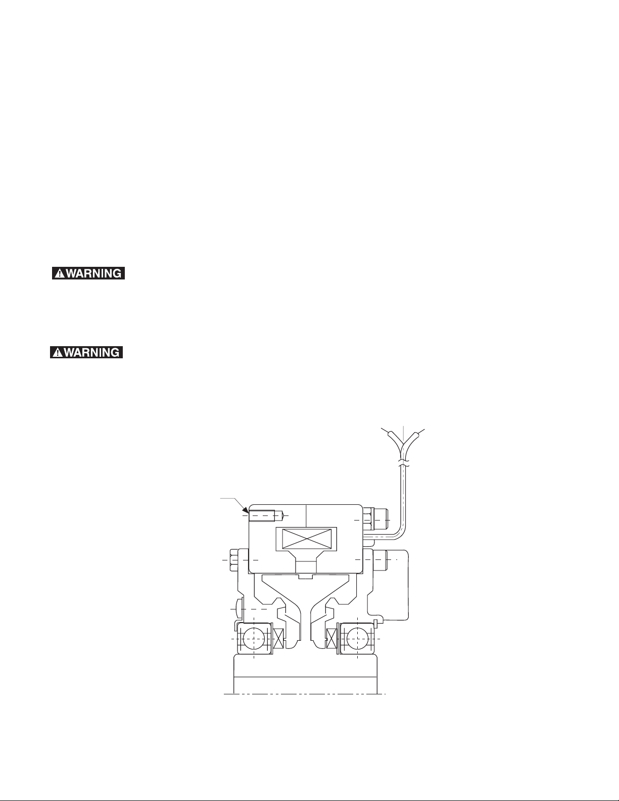
Tapped Holes
for mounting
Figure 1 - PRB-H Basic Model
Failure to follow these instructions may result in product damage, equipment damage, and serious or fatal injury to
personnel.
Make sure all power is turned
off to this equipment when installing, as
injury (or even death) may result from contact
with live wires or rotating shafts.
Page 3
3
Installation Instructions
Introduction
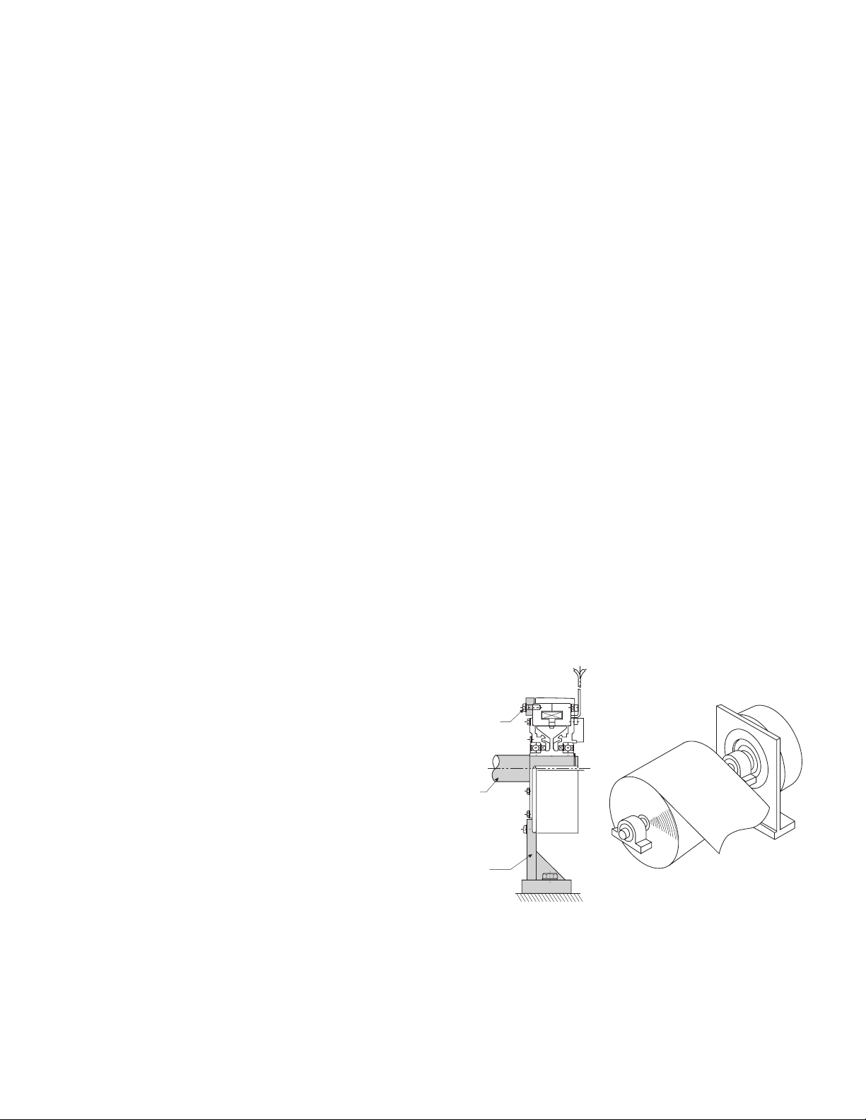
The PRB-H brake mounts to a vertical surface
and the customer's shaft is secured in the input
hub of the unit. See Figure 2.
Pre-Mounting
Note: Unit performance can be affected by
prolonged exposure to humid environments.
Please store in a dry location.
Note: The equipment covered by this service
manual must be installed in accordance with
these instructions. Failure to do so may damage the equipment and void the warranty.
1. Remove your magnetic particle brake from its
shipping carton and inspect it thoroughly to
ensure that it has arrived in good condition.
When handling, please take care not to damage lead wires.
2. Check the input hub to make sure it turns
freely. The magnetic powder inside the unit
may settle due to shock and vibration caused
during shipping. If hub rotation is difficult,
turn the unit upside down and gently tap it to
loosen the powder.
3. Make sure the location chosen for mounting
will not expose the unit to water or oil as
these contaminants may affect unit performance. If the unit is mounted next to a gearbox, special care should be taken to prevent
oil from working its way into the unit.
4. If coupling(s) are used to connect to the drive
system, the mounting surface must properly
locate the housing to ensure that alignment is
within tolerance of the coupling(s).
Capscrews
Shaft
Mounting
Bracket
Figure 2*
PRB-H Installation Example
Mounting
Note: For proper function, mount magnetic
particle units horizontally.
Mounting dimensions for the PRB-H can be
found on page 6 & 7.
Step 1: Bolt Unit Into Place
Mount the unit to a vertical surface with customer supplied fasteners. PRB-H brake should
be mounted to a vertical surface. See Figure 2.
Step 2: Make Mechanical Connections
Slide the input shaft into the brake's bore. The
shaft should be supported from moving axially
using external bearings, snap rings, or locking
collars.
*Note: Shaded items are customer supplied.
Warner Electric • 800-825-9050 819-0370
Page 4

4
Warner Electric • 800-825-9050 819-0370
Electrical Connections
To avoid injury (or even death),
always make certain all power is off before
attempting to install or service the control or
any electrical equipment.
Warner Electric Magnetic Particle brakes operate on DC voltage. Warner Electric offers a full
line of AC powered controls to meet the needs
of almost every application. The service and
installation instructions included with each
Warner Electric control show the proper electrical connections for the brake.
If a varistor is supplied with your unit, it is not
required for use with a Warner Electric control.
All Warner Electric controls have built in suppression.
After wiring your Magnetic Particle brake, check
the control circuit. Without rotating the input
hub, verify that voltage is applied when the control output is turned on. Also, if appropriate, set
the current for the proper output. Your magnetic
particle unit is now ready for operation. For
information on start up and maintenance, see
below.
Start Up
The powder in the magnetic particle units sometimes settles during shipping and will need to be
redistributed. A simple run in procedure should
be performed to ensure proper performance.
Run in Procedure
Note: Before running in the brake, make sure it
does not bind. See step 2 of the premounting
instructions.
Set the control output voltage to 5 - 6 volts.
Turn off the control and run the input for one
minute. Then run the input at a speed close to,
but not exceeding, 1000 RPM. Cycle the unit at
5 or 6 volts for five seconds on and ten seconds
off. Repeat this for 20 cycles.
When the powder is redistributed properly,
torque will be consistent and proportional to
current.
Maintenance
Heat
If the heat generated during operation is greater
than the heat dissipation capability of the unit, it
will overheat. The maximum allowable surface
temperature for a PRB-H series unit is 194
degrees F.
Slip Applications
The heat generated is proportional to the torque
and slip RPM. Care must be taken when adjusting torque on the control to make sure that the
unit heat dissipation capacity is not exceeded.
Refer to the sizing procedure in the catalog to
make sure the brake has adequate heat dissipation capability. Also, do not increase the slip
speed or the torque without verifying that the
unit can dissipate the heat.
Cycling Applications
In cycling applications, the speed and inertia of
the load and the stopping frequency determines
the heat generated. Refer to the selection procedure in the catalog to verify that your brake
can handle the thermal energy generated in your
application. Also, do not increase the speed,
cycle rate, or inertia without checking the unit's
ability to dissipate the heat generated.
Contamination
Do not expose the brake to water or oil. If water
or oil gets in the powder cavity, performance
may be affected. If the brake is mounted next to
a gearbox, special care must be taken to prevent oil from entering the unit.
Page 5

5
Warner Electric • 800-825-9050 819-0370
Electrical Data
Electrical Coil Data (PRB-H)
Unit Size Voltage Resistance Amperes Watts Torque Build Up Torque Decay
[ohms @ 75° F (25°C)] [@ 75° F (25°C)] [@ 75° F (25°C)] (msec) (msec)
1.2 24 31.6 .760 18.2 138 38
2.5 24 25.6 . 934 22.5 175 40
524 19.3 1.24 29.8 194 70
10 24 14.8 1.62 38.9 345 95
20 24 12.5 1.93 46.2 440 120
Note: Build up time equals time for torque to build to approximately 63.2% of steady state value
after a step change in voltage. Decay time equals time for current to drop to approximately 36.8%
of steady state value after a voltage change.
Mechanical Data
Drag Maximum Input
Unit Part Torque Torque Speed InertiaI Weight
Number (lb. ft.) (lb. ft.) (rpm) (ft. lb.2) (lbs.)
PRB-1.2H 5401-169-331 8.6 .26 1800 .104 11
PRB-2.5H 5401-169-341 18 .54 1800 .161 15
PRB-5H 5401-169-351 36 1.1 1800 .453 29
PRB-10H 5401-169-361 72 2.2 1800 1.51 57
PRB-20H 5401-169-371 144 4.3 1800 4.46 101
Page 6

6
Warner Electric • 800-825-9050 819-0370
PRB-H Dimensions
L
300 mm
(11.8 in.)
D
C
B
H
G
E
F
G
A
5 mm
(.20 in.)
J
I
K
Page 7

7
Warner Electric • 800-825-9050 819-0370
PRB-H Dimensional Data
Note: All dimensions are nominal unless otherwise noted.
Bore Dimensions L
Model A B C D E F G H I J K Depth No. Bolt
mm mm mm mm mm mm mm mm (in.) mm (in.) mm (in.) mm (in.) Thread mm of Circle
(in.) (in.) (in.) (in.) (in.) (in.) (in.) Size (in.) Holes mm
(in.)
PRB-1.2H 136 63 42 7 5.5 53 109 136.000 5.3543 15.018 0.5913 5.028 0.1980 17.250 0.6791 M5 10 6 125
(5.35) (2.48) (1.65) (0.28) (0.22) (2.09) (4.29) 135.960 5.3528 15.000 0.5906 5.010 0.1972 17.000 0.6693 (0.39) (4.92)
PRB-2.5H 160 73 47 7.5 6.5 60 124 160.000
6.2992 20.021 0.7882 5.028 0.1980 22.250 0.8760 M5 10 6 148
(6.30) (2.87) (1.85) (0.30) (0.26) (2.36) (4.88) 159.960 6.2976 20.000 0.7874 5.010 0.1972 22.000 0.8661 (0.39) (5.83)
PRB-5H 195 84.5 57 8 5 67 149 195.000
7.6772 30.021 1.1819 7.035 0.2770 33.250 1.3091 M6 12 6 181
(7.68) (3.33) (2.24) (0.31) (0.20) (2.64) (5.87) 195.954 7.7147 30.000 1.1811 7.013 0.2761 33.000 1.2992 (0.47) (7.13)
PRB-10H 250 104 68 8.5 5 78 188 250.000
9.8425 30.021 1.1819 7.035 0.2770 33.250 1.3091 M6 12 8 233
(9.84) (4.09) (2.68) (0.33) (0.20) (3.07) (7.40) 249.954 9.8407 30.000 1.1811 7.013 0.2761 33.000 1.2992 (0.47) (9.17)
PRB-20H 305 128.5 80 12 7.5 95 234 305.000
12.0079 40.025 1.5758 10.035 0.3951 43.750
1.7224 M8 12 8 282
(12.01) (5.06) (3.15) (0.47) (0.30) (3.74) (9.21) 304.948 12.0058 40.000 1.5748 10.013 0.3942 43.500 1.7126 (0.47) (11.10)
(
)
(
)
(
)
(
)
(
)
(
)
(
)
(
)
(
)
(
)
(
)
(
)
(
)
(
)
(
)
(
)
(
)
(
)
(
)
(
)
Page 8

Warranty
Warner Electric LLC warrants that it will repair or replace (whichever it deems advisable) any
product manufactured and sold by it which proves to be defective in material or workmanship
within a period of one (1) year from the date of original purchase for consumer, commercial or
industrial use.
This warranty extends only to the original purchaser and is not transferable or assignable without
Warner Electric LLC’s prior consent.
Warranty service can be obtained in the U.S.A. by returning any defective product, transportation
charges prepaid, to the appropriate Warner Electric LLC factory. Additional warranty information
may be obtained by writing the Customer Satisfaction Department, Warner Electric LLC, 449
Gardner Street, South Beloit, Illinois 61080, or by calling 815-389-3771.
A purchase receipt or other proof of original purchase will be required before warranty service is
rendered. If found defective under the terms of this warranty, repair or replacement will be made,
without charge, together with a refund for transportation costs. If found not to be defective, you
will be notied and, with your consent, the item will be repaired or replaced and returned to you
at your expense.
This warranty covers normal use and does not cover damage or defect which results from
alteration, accident, neglect, or improper installation, operation, or maintenance.
Some states do not allow limitation on how long an implied warranty lasts, so the above limitation
may not apply to you.
Warner Electric LLC’s obligation under this warranty is limited to the repair or replacement of the
defective product and in no event shall Warner Electric LLC be liable for consequential, indirect,
or incidental damages of any kind incurred by reason of the manufacture, sale or use of any
defective product. Warner Electric LLC neither assumes nor authorizes any other person to give
any other warranty or to assume any other obligation or liability on its behalf.
WITH RESPECT TO CONSUMER USE OF THE PRODUCT, ANY IMPLIED WARRANTIES WHICH
THE CONSUMER MAY HAVE ARE LIMITED IN DURATION TO ONE YEAR FROM THE DATE OF
ORIGINAL CONSUMER PURCHASE. WITH RESPECT TO COMMERCIAL AND INDUSTRIAL
USES OF THE PRODUCT, THE FOREGOING WARRANTY IS IN LIEU OF AND EXCLUDES ALL
OTHER WARRANTIES, WHETHER EXPRESSED OR IMPLIED BY OPERATION OF LAW OR
OTHERWISE, INCLUDING, BUT NOT LIMITED TO, ANY IMPLIED WARRANTIES OF
MERCHANTABILITY OR FITNESS.
Some states do not allow the exclusion or limitation of incidental or consequential damages, so
the above limitation or exclusion may not apply to you. This warranty gives you specic legal
rights and you may also have other rights which vary from state to state.
Changes in Dimensions and Specifications
All dimensions and specications shown in Warner Electric catalogs are subject to change without
notice. Weights do not include weight of boxing for shipment. Certied prints will be furnished
without charge on request to Warner Electric.
Warner Electric LLC
31 Industrial Park Road • New Hartford, CT 06057
815-389-3771 • Fax: 815-389-2582
www.warnerelectric.com
P-223-3 819-0370 6/05 Printed in USA
 Loading...