

Page 1
MTB II Modular Tension Brakes
P-259-1
819-0342
Installation Instructions
Page 2
Introduction
The instructions on this sheet cover installation
of all replacement components available for
modular tension brakes. These instructions are
divided into sections as designated by the
introductory headlines. Please check these
headings to locate the proper instruction for the
replacement components being installed.
Friction components, the most frequently
replaced items, are found near the end of these
instructions.
Failure to follow these
instructions may result in product damage,
equipment damage, and serious or fatal
injury to personnel.
Contents
Assembling Armature to Armature Carrier . . . . . . . .2
Installing the Armature Assembly . . . . . . . . . . . . . .3
Tapered Bushing Carrier . . . . . . . . . . . . . . . . . . . . .3
Straight Bore Carrier . . . . . . . . . . . . . . . . . . . . . . . .3
Mounting the Magnets . . . . . . . . . . . . . . . . . . . . . . .3
Adjusting the Armature Assembly . . . . . . . . . . . . . .4
Control Connection . . . . . . . . . . . . . . . . . . . . . . . . .5
Servicing Friction Surfaces . . . . . . . . . . . . . . . . . . .5
Rebuild Procedure . . . . . . . . . . . . . . . . . . . . . . . . . .5
Removal of the Armatures . . . . . . . . . . . . . . . . . . . .5
Replacement of Friction Pads . . . . . . . . . . . . . . . . .6
Assemble and Install the Armature Assembly . . . . .6
Wear-In . . . . . . . . . . . . . . . . . . . . . . . . . . . . . . . . . . .6
Modification of Straight Bore Armature Carriers . . .6
Bulk Head Mounting Brackets . . . . . . . . . . . . . . . . .7
Direct Mounting . . . . . . . . . . . . . . . . . . . . . . . . . . . .8
Universal Mounting . . . . . . . . . . . . . . . . . . . . . . . . .9
Brake Assemblies and Part Numbers . . . . . . . . . .10
Assembling the Armature to the Armature
Carrier
The beveled edge on the inside diameter of the
armature is to be assembled facing the armature
carrier. Tighten all screws to 7-9 ft. lbs. torque.
(Figure 1)
Figure 1
Using the screws and lockwashers provided
with the armature(s), mount the armature(s) to
the armature carrier. If a single armature is used,
mount it on the appropriate side of the hub. Be
sure to allow easy access to the tapered
bushing. (Figure 3)
Figure 2
Warner Electric • 800-825-9050 819-0342
2
Page 3

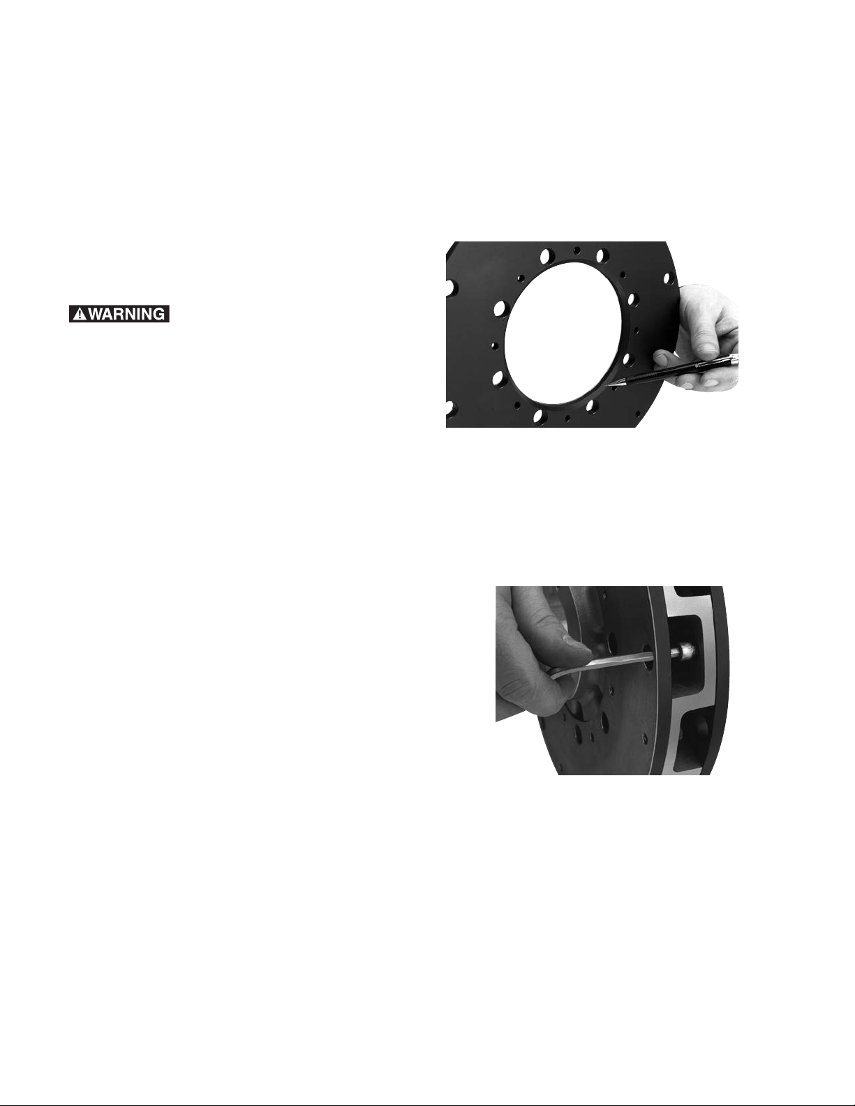
Installing the Armature Assembly
Straight Bore Carrier
Insert the tapered bushing loosely into the
armature assembly and start the capscrews with
their lockwashers. (Figure 3)
Figure 3
Tapered Bushing Carrier
Install the key in the machine shaft keyway.
(Figure 4)
The armature carrier may be ordered with a
range of standard straight bores suitable for
various standard mounting products. Custom
bores are also available to adapt to special
devices. Consult the factory for information on
modifications.
Mounting the Magnets
If mounting brackets are used, mount the
brackets to the machine frame using the holes
prepared earlier. (Figure 6)
Figure 4
Slide the armature carrier assembly onto the
shaft to the approximate position required for
operation. Do not tighten the bushing yet
since final positioning will be required later.
(Figure 5)
Figure 6
If a Warner magnet carrier is used, place the
carrier on a horizontal surface with the pins
facing up. (Figure 7)
Figure 7
Figure 5
Warner Electric • 800-825-9050 819-0342
3
Page 4
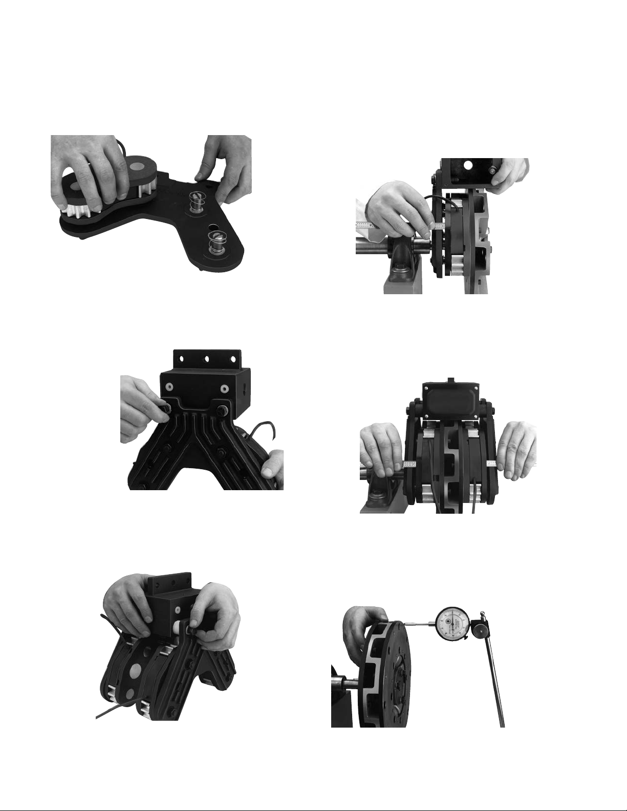
If the magnets are to be free mounted, mount
the pins as required according to the free mount
layout. Place the magnets on the pins with the
lead wires outboard. (Figure 8)
Figure 8
Bolt the magnet carriers directly to the
mounting bracket with furnished capscrews
and lockwashers. (Figure 9)
Figure 9
Adjusting the Armature Assembly
For an armature assembly with a single
armature face, position the armature assembly
so the space between the back of the magnet
and the magnet carrier assembly is
approximately 1/4’’. (Figure 11)
Figure 11
For a dual armature assembly, position armature
assembly for approximately equal space behind
the magnets on each side. (Figure 12)
Note: If the universal mounting bracket is used
AND the armature assembly has 2 armatures,
the furnished spacers must be installed between
Figure 12
the magnet carriers and bracket. Tighten all magnet carrier mounting bolts securely. (Figure 10)
Tighten the armature assembly to the shaft. The
maximum axial runout on either face is to be
less than .015 T.I.R. (Figure 13)
Figure 10
Figure 13
Warner Electric • 800-825-9050 819-0342
4
Page 5

If the bore on the aluminum carrier has been
modified, the radial runout of the aluminum
carrier is not to exceed .008 inches. (Figure 14)
Figure 14
Servicing Modular Tension Brake Friction
Surfaces Magnet Inspection
Each magnet is supplied with visual wear
indicators. When the magnet is worn to these
indicators, pad replacement is required. (Figure
16)
If the magnet is supplied with an electronic wear
indicator, a signal will be sent to the control to
indicate replacement is required.
Both the visual and electronic wear indicators
are preset to indicate replacement at 85 percent
wear out, allowing 15 percent more life for
planned maintenance.
Control Connection
Contact with live wires can
cause injury or death. Be sure all power is
turned off before starting the connection
process.
Wire the magnets to the control in accordance
with the instructions included with the control.
Warner Electric offers several different systems
ranging from a simple manual control through a
roll follower system to several types of closed
loop systems. For more information, ask for
catalog P-771. (Figure 15)
A used armature should not be resurfaced
nor turned over to be used on the other side.
Figure 16
Rebuild Procedure
Note: When disconnecting and reconnecting
leads to the magnet, the input power must be
shut off to the control system.
Removal of the Armatures
If required, remove the armature assembly from
the shaft.
Figure 15
Remove the brackets and magnet carriers to
gain access to the armature(s). Remove the
armature face(s) with the armature in place, if
possible. If machine framework or components
prevent face(s) removal, the entire armature
assembly may have to be separated from the
brake hub and removed from the machine to
access the face(s).
Warner Electric • 800-825-9050 819-0342
5
Page 6

Since the armature and magnet faces are the
only tension brake components which sustain
wear, replaceable faces are offered for both, to
maximize brake life. The following instructions
deal with wear assessment and friction face
replacement.
Assemble and Install
the Armature Assembly
Follow the previous instructions for assembly
and installation of the armature assembly.
Wear-In
Replacement of Friction Pads
Remove the old pads from the magnets.
(Figure 17)
Figure 17
If the magnets are supplied with electronic wear
indicators, replace the hexagon brass contacts
(Warner Electric part no. 274-1029) on each
magnet. Tighten to 6-8 in. lb. torque. Attach the
new pads to the magnets. Tighten each screw
to 7-9 ft. lbs. torque. (Figure 18)
Replacement of the friction faces will require a
new wear-in period as the pads seat themselves
on the armature.
With a closed-loop control system, such as
dancer or load cell control, no changes in torque
will be apparent during wear-in. The control
system will compensate for any variations.
With a manual control system, however, an
unburnished brake will produce only about 75%
of its fully burnished torque. If full torque is
required at start-up, the brake should have a
preburnish period to fully seat the magnets on
the armature to provide full torque. If this is not
possible, several torque adjustment settings will
be required during the initial hours of on line
operation. Burnishing is the process of mating
the friction surfaces of a brake that is mounted
and ready for service.
Modification of Straight Bore
Armature Carriers
The straight bore armature carrier may be
modified to accept a variety of mountings.
If a modification to the armature is required, the
modified assembly must meet the following
requirements. With the armature assembly fully
installed on the shaft:
1. Maximum radial runout of the aluminum
carrier is .008”
2. Maximum axial runout on either face is .015”
Figure 18
Warner Electric • 800-825-9050 819-0342
6
T.I.R.
Page 7

Dimensions
7.250 (184.2) MAX. 7.250 (184.2) MAX.
3/4-10 UNC-2A
THREAD (2)
.200
(5.08)
SET-UP
1.644
(41.8)
EE
F
A
1.070
(27.2)
MIN.
MOUNTING
SPACER
3.440
(87.4)
3.125
(79.4)
.200
(5.08)
SET-UP
8.750 .003
(222.2 .762)
4.375 .015
(111.1 .381)
B
RADIUS
D
DIA.
C
BORE
G
DEG.
1.322
(33.58)
Modular Tension Brake
Bulk Head Mounting Brackets
Dual Armature Single Armature
inch (metric)
All Dimensions Nominal unless specified
Armature AB C BORE DEFG
Size Max. Stock* Bushing Max. Max. Max. Degree
10" 5.260 ± .020 7.750 1.750 .500–1.750 10.020 .479 3.55 180
(133.6 ± 0.5) (196.9) (44.45) (14.0–42.0) (254.5) (12.2) (88.9)
13" 6.822 ± .020 9.300 3.375 1.125–3.750 13.520 1.219 5.687 108 &
(173.3 ± 0.5) (236.2) (85.73) (28.0–95.0) (343.4) (31.0) (144.4) 144
15" 7.760 ± .020 10.230 3.375 1.125–3.750 15.325 1.219 6.875 120
(197.1 ± 0.5) (259.9) (85.73) (28.0–95.0) (389.3) (31.0) (174.6)
20" 10.250 ± .020 12.500 — 2.375–5.500 20.020 2.720 4.380 —
(260.4 ± 0.5) (317.5) ——(508.5) (69.1) (111.3)
* Stock bore is straight bore for use with Trantorque bushing.
Warner Electric • 800-825-9050 819-0342
7
Page 8

Modular Tension Brake–Direct Mounting
C
BORE
D
DIA.
G
DEG.
1.795
(45.6)
1.644
(41.8)
E
1.830
(46.6)
.865
(22.0)
MAX.
.350
(8.9)
MAX.
BULK
HEAD
.200
(5.08)
SET-UP
F
E
3.500 .002
(88.9 .051)
1.750 .015
(44.5 .381)
MAGNET
ASSEMBLY
A
1.322
(33.58)
7.080 (179.8) MAX.
5.330 .020
(135.4 .508)
.350
(8.9)
MAX.
BULK
HEAD
.200
(5.08)
SET-UP
Dual Armature Single Armature
inch (metric)
All Dimensions Nominal unless specified
Armature AB C BORE DE FG
Size Max. Stock* Bushing Max. Max. Max. Degree
10" 3.350 ± .020 N/A 1.750 .500–1.750 10.020 .479 3.550 120
13" 5.215 ± .020 N/A 3.375 1.125–3.750 13.520 1.219 5.687 72
(85.1 ± 0.5) (N/A) (44.45) (14.0–42.0) (254.5) (12.2) (88.9)
(132.5 ± 0.5) (N/A) (85.73) (28.0–95.0) (343.4) (31.0) (144.4)
15" 5.850 ± .020 N/A 3.375 1.125–3.750 15.325 1.219 6.875 60
(148.6 ± 0.5) (N/A) (85.73) (28.0–95.0) (389.3) (31.0) (174.6)
20" 8.125 ± .040 N/A — 2.375–5.500 20.020 2.720 ——
(206.4 ± 1.0) (N/A) ——(508.5) (69.1) —
* Stock bore is straight bore for use with Trantorque bushing.
Warner Electric • 800-825-9050 819-0342
8
Page 9

Modular Tension Brake–Universal Mounting Brackets
.404
.395
10.26
10.03
3.500 .003
(88.9 .762)
1/2-14 NPT
B
Radius
3.300
(83.8)
2.400
(61.0)
.500
(12.7)
.200
(5.08)
SET-UP
.200
(5.08)
SET-UP
1.644
(41.8)
E
E
F
1.500
(38.1)
5.085 (129.2) MAX.
1.835
(46.6)
.500
(12.7)
1/2-14 NPT
(Shown with
Dust Plug)
HOLES
1.750
(44.5)
1.210 (30.7)
.630
(16.0)
MIN.
A
C
BORE
D
DIA.
G
DEG.
(
)
1.322
(33.58)
7.125 (181.0) MAX.
inch (metric)
All Dimensions Nominal unless specified
Armature AB C BORE DE FG
* Stock bore is straight bore for use with Trantorque bushing.
Dual Armature Single Armature
Size Max. Stock* Bushing Max. Max. Max. Degree
10" 8.625 ± .020 9.500 1.750 .500–1.750 10.020 .479 3.550 180
(219.0 ± 0.5) (241.3) (44.45) (14.0–42.0) (254.5) (12.2) (88.9)
13" 10.187 ± .020 11.000 3.375 1.125–3.750 13.520 1.219 5.687 108 &
(258.7 ± 0.5) (279.4) (85.73) (28.0–95.0) (343.4) (31.0) (144.4) 144
15" 11.125 ± .020 12.000 3.375 1.125–3.750 15.325 1.219 6.875 120
(282.6 ± 0.5) (304.8) (85.73) (28.0–95.0) (389.3) (31.0) (174.6)
20" 13.470 ± .020 14.250 — 2.375–5.500 20.020 2.720 4.380 —
(340.4 ± 0.5) (362.0) ——(508.5) (69.1) (111.3)
Warner Electric • 800-825-9050 819-0342
9
Page 10

Brake Assemblies and Part Numbers
6
6
5
9
2
2
2a
1
3
9a
9b
4
4a
8
7
MTB II
Part Numbers
Item Description 10" Armature 13" Armature 15" Armature 20" Armature
1 Armature Carrier (Bushing Enters from Flush
Side of Carrier as Shown) 295-0021 295-0023 295-0019 –
Armature Carrier Reverse Taper (Bushing
Enters from Extended Side of Carrier 295-0031 295-0030 295-0029 –
Armature Carrier (Straight Bore) 295-0026 295-0027 295-0028 –
2 Armature (Replaceable Face) 5216-101-025 5216-101-026 5216-101-024 –
2a Armature Mounting Accessory (included with Armature 5216-101-023 5216-101-023 5216-101-023 –
3 Bushing (Customer Supplied) Taper Bore Browning P1 Browning R1 Browning R1 _
Straight Bore Use Trantorque. Consult Warner Electric
4 Female Pin Kit (includes 2 Pins) 5216-101-030 5216-101-030 5216-101-030 5216-101-030
4a Male Pin Kit (includes 32 Pins with Nuts and Lockwashers) 5216-101-029 5216-101-029 5216-101-029 5216-101-029
Magnet Carriers
5 Single Magnet Carrier Assembly 5216-295-004 5216-295-004 5216-295-004 5216-295-004
6 Dual Magnet Carrier Assembly 5216-295-005 5216-295-006 5216-295-007 5216-295-007
Carrier Brackets
7 Universal Mounting Bracket, Series 10-0, 13-0, & 20-0 (2) 5216-101-020 5216-101-020 5216-101-020 5216-101-020
Universal Mounting Bracket, Series 10-10, 13-13, & 20-20 (2) 5216-101-021 5216-101-021 5216-101-021 5216-101-021
8 Bulk Head Mounting Bracket (3) 5216-101-022 5216-101-022 5216-101-022 5216-101-022
Magnets
9 Magnet Assembly, Standard 5216-631-010 5216-631-010 5216-631-010 5216-631-010
Magnet Assembly, HICO 5216-631-013 5216-631-013 5216-631-013 5216-631-013
9a Friction Pad, Standard (Replacement Part Only) 5216-101-028 5216-101-028 5216-101-028 5216-101-028
Friction Pad, HICO 5216-631-031 5216-631-031 5216-631-031 5216-631-031
9b Preload Spring (1) (Included with Magnets) 808-0008 808-0008 808-0008 808-0008
10 Magnet Assembly with Wear Indicator 5216-631-009 5216-631-009 5216-631-009 5216-631-009
10a Friction Pad with Wear Indicator (Replacement Part Only) 5216-101-027 5216-101-027 5216-101-027 5216-101-027
(1) Two of each required for each brake magnet.
(2) Includes magnet carrier (4 & 5) mounting hardware.
(3) Includes magnet mounting hardware, bracket mounting bolts and spacers.
Browning is a registered trademark of Emerson Electric Co., Trantorque is a registered trademark of Trantorque Corporation.
Warner Electric • 800-825-9050 819-0342
10
Page 11

Warner Electric • 800-825-9050 819-0342
11
Page 12

Warranty
Warner Electric LLC warrants that it will repair or replace (whichever it deems advisable) any
product manufactured and sold by it which proves to be defective in material or workmanship
within a period of one (1) year from the date of original purchase for consumer, commercial or
industrial use.
This warranty extends only to the original purchaser and is not transferable or assignable without
Warner Electric LLC’s prior consent.
Warranty service can be obtained in the U.S.A. by returning any defective product, transportation
charges prepaid, to the appropriate Warner Electric LLC factory. Additional warranty information
may be obtained by writing the Customer Satisfaction Department, Warner Electric LLC, 449
Gardner Street, South Beloit, Illinois 61080, or by calling 815-389-3771.
A purchase receipt or other proof of original purchase will be required before warranty service is
rendered. If found defective under the terms of this warranty, repair or replacement will be made,
without charge, together with a refund for transportation costs. If found not to be defective, you
will be notified and, with your consent, the item will be repaired or replaced and returned to you
at your expense.
This warranty covers normal use and does not cover damage or defect which results from
alteration, accident, neglect, or improper installation, operation, or maintenance.
Some states do not allow limitation on how long an implied warranty lasts, so the above limitation
may not apply to you.
Warner Electric LLC’s obligation under this warranty is limited to the repair or replacement of the
defective product and in no event shall Warner Electric LLC be liable for consequential, indirect,
or incidental damages of any kind incurred by reason of the manufacture, sale or use of any
defective product. Warner Electric LLC neither assumes nor authorizes any other person to give
any other warranty or to assume any other obligation or liability on its behalf.
WITH RESPECT TO CONSUMER USE OF THE PRODUCT, ANY IMPLIED WARRANTIES WHICH
THE CONSUMER MAY HAVE ARE LIMITED IN DURATION TO ONE YEAR FROM THE DATE OF
ORIGINAL CONSUMER PURCHASE. WITH RESPECT TO COMMERCIAL AND INDUSTRIAL
USES OF THE PRODUCT, THE FOREGOING WARRANTY IS IN LIEU OF AND EXCLUDES ALL
OTHER WARRANTIES, WHETHER EXPRESSED OR IMPLIED BY OPERATION OF LAW OR
OTHERWISE, INCLUDING, BUT NOT LIMITED TO, ANY IMPLIED WARRANTIES OF
MERCHANTABILITY OR FITNESS.
Some states do not allow the exclusion or limitation of incidental or consequential damages, so
the above limitation or exclusion may not apply to you. This warranty gives you specific legal
rights and you may also have other rights which vary from state to state.
Changes in Dimensions and Specifications
All dimensions and specifications shown in Warner Electric catalogs are subject to change without
notice. Weights do not include weight of boxing for shipment. Certified prints will be furnished
without charge on request to Warner Electric.
Warner Electric LLC
31 Industrial Park Road • New Hartford, CT 06057
815-389-3771 • Fax 815-389-2582
www.warnerelectric.com
P-259-1 819-0342 12/11 Printed in USA
An Altra Industrial Motion Company
 Loading...