

Page 1
P-2026-WE
SM592-gb-02/08
Wrap Spring Clutches & Brakes
CB & Super CB Series
Service Manual
Page 2
CONTENTS
1 Assembly instructions CB-2 - CB-5 2-3
1.1 Disassembly 3
1.2 Removal of anti-overrun spring 3
1.3 Assembly 3
2 Assembly instructions CB-6 - CB-10 4-5
2.1 Disassembly 5
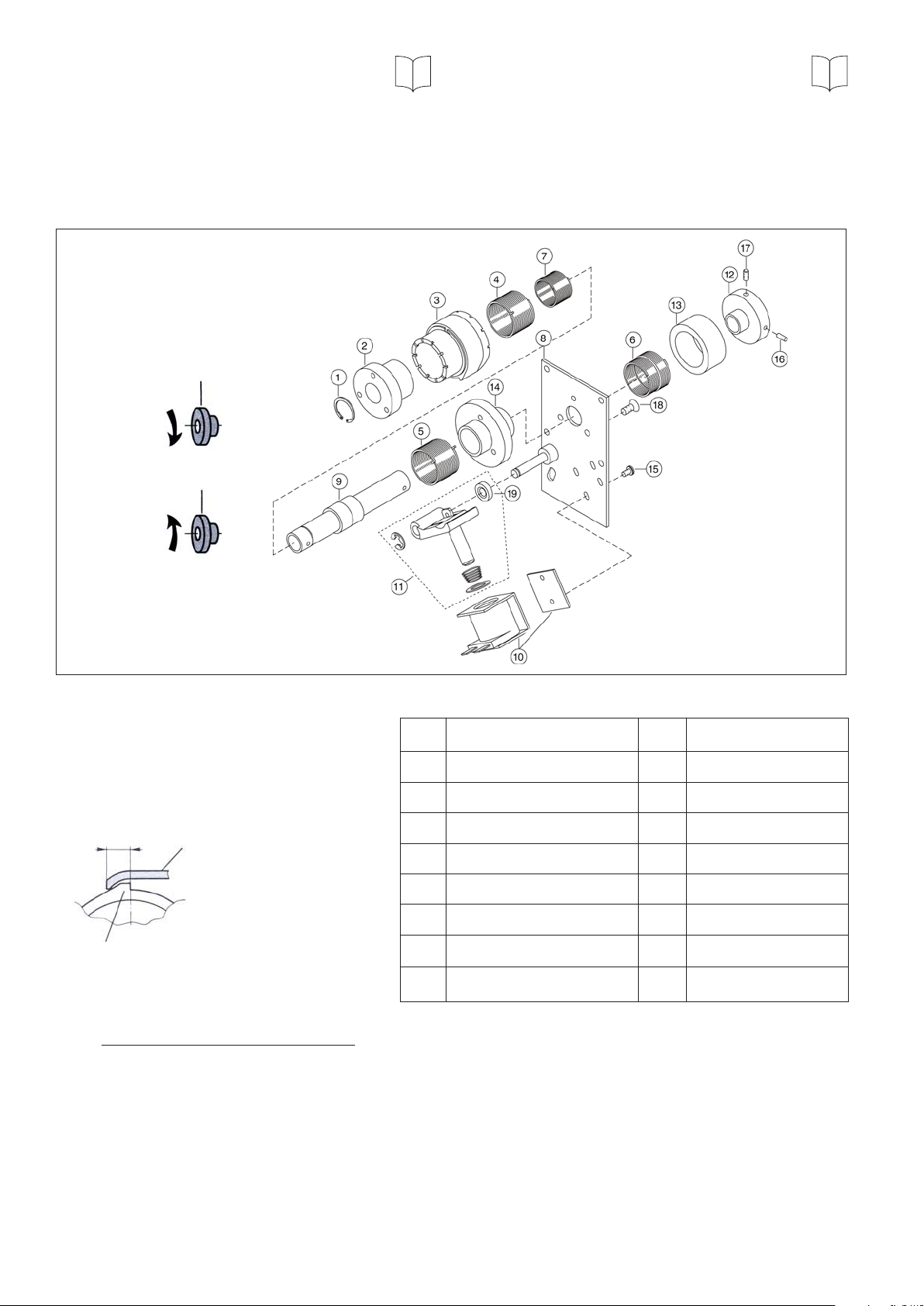
Exploded drawing
CB-2 - CB-5
CW
2.2 Removal of anti-overrun spring 5
2.3 Assembly 5
3 Service information 6
3.1 Adjustment of the control collar 6
3.2 Actuator setting 6
4 Lubrication 7
CCW
Overtravel OT
CB-2: 2,3 - 4,8 mm
CB-4: 4,8 - 7,8 mm
CB-5: 3,8 - 6,3 mm
OT
Stop collar
Actuator
1 Assembly instructions CB-2 - CB-5
1 Circlip 10 Coil assembly
2 Input hub 11 Actuator assembly
3 Control collar 12 Anti-backup hub
4 Clutch spring 13 Dust cover
5 Brake spring 14 Brake hub
6 Anti-backup spring 15 Screw
7 Anti-overrun spring 16 Spring pin
8 Mounting plate 17 Set screw
9 Shaft assembly 18 Screw
CB-Products are shipped as complete and pre-set units. Disassembly and assembly is only needed if
modifications or repair work is required.
The exploded drawing shows a CB-5 unit. The principle also applies to the CB-2 and CB-4 units.
2 Warner Electric Europe • +33 (0)2 41 21 24 24 P-2026-WE • 11/12
Page 3

1.1 DISASSEMBLY
1. Brake engaged, input hub (2) freely rotatable, remove circlip (1).
2. Remove input hub (2) by rotating in the drive direction (remove anti-overrun spring (7), if present).
3. Remove control collar (3), by extracting towards the control tang of clutch spring (4).
4. Remove springs (clutch and brake).
5. If necessary remove anti-backup spring (6), (13), (16). To remove the spring pin (16), special tools are
required.
1.2 REMOVAL OF ANTI-OVERRUN SPRING (7)
All CB units are normally equipped with an anti-overrun spring (7). If the anti-overrun is not required, e.g. the
input hub (2) must be able to rotate in both directions, execute the following :
1. Mark the spring tang location on control collar (3).
2. Fully wrap down the brake spring (output in stop position).
3. Remove circlip (1) and input hub (2).
4. Remove the anti-overrun spring (7).
5. Assemble the input hub (2) with circlip (1).
6. Check the overtravel specification (OT).
1.3 ASSEMBLY
1. Assemble anti-backup spring (6), dust cover (13) and anti-backup hub (12) (if required).
2. Assemble brake spring (5) and clutch spring (4) on sleeve (9) (output tangs - clutch, brake - in the sleeve).
3. Assemble control collar (3) over clutch spring (4), by extending control tang of the clutch spring by using long
nose pliers (put pliers into collar (3) first).
4. The control tang of the brake spring (5) is located in one of the nine slots of the control collar. The control
tang of the clutch spring (4) - slightly precharged -lies in one of the ten slots.
5. Rotate output into STOP position. Assemble input hub (2) (not secured).
6. Differential setting of clucth/brake (overtravel OT). Actuator is in contact with stop of control collar (3)
Rotate output into STOP position. Pull backwards input hub (2), remove control tang of clutch spring (4) out
of slot of control collar. Open clutch spring (4), to obtain distance OT. Push spring and input hub (2) back
again. Lift actuator, the control collar (3) should overtravel distance OT. If OT is not reached. put control
tang of brake spring(5) in another of the nine slots and repeat procedure until OT is reached.
7. Assemble circlip (1) at input hub (2).
8. If anti-overrun is required : rotate output into STOP position. Remove circlip (1) and input hub (2). Screw
carefully anti-overrun spring (7) into output hub. Assemble input hub (2) by rotating in the drive direction.
Assemble circlip (1).
9. Check actuator setting (11).
Warner Electric Europe • +33 (0)2 41 21 24 24 P-2026-WE • 11/12 3
Page 4

Exploded drawing
CB-6 - CB-10
CW
CCW
Overtravel OT
CB-6: 4,8 - 9,4 mm
1 Circlip 11 Screw
2 Input hub 12 Actuator assembly
CB-7: 9,4 - 12,7 mm
CB-8: 9,4 - 12,7 mm
3 Control collar 13 Solenoid assembly
CB-10: 15,7 - 19,0 mm
4 Clutch spring 13a Washer
OT
Actuator
5 Anti-overrun spring 13b Lockwasher
6 Shaft assembly 13c Cap screw
7 Anti-backup spring 14 Cap screw
8 Brake spring 15 Lockwasher
Stop collar
9 Brake hub 16 Set screw
10 Mounting plate 17 Spacer
2 Assembly instructions CB-6 - CB-10
CB-Products are shipped as complete and pre-set units. Disassembly and assembly is only needed if
modifications or repair work is required.
The exploded drawing shows a CB-8 unit. The principle also applies to the CB-6 and CB-10 units.
4 Warner Electric Europe • +33 (0)2 41 21 24 24 P-2026-WE • 11/12
Page 5

2.1 DISASSEMBLY
1. Brake engaged, input hub (2) freely rotatable, remove circlip (1).
2. Remove input hub (2) by rotating in the drive direction (remove anti-overrun spring (5), if present).
3. Control collar (3), released (actuator not in contact with STOP). Remove circlip (1) at mounting
plate (10).
4. Remove output sleeve (6) by rotating in the drive direction.
5. Remove anti-backup spring (7). DO NOT disassemble brake hub (9).
6. Remove control collar (3) by extracting towards the control tang of the brake spring (8).
7. Remove springs (clutch and brake).
2.2 REMOVAL OF ANTI-OVERRUN SPRING (5)
All CB units are normally equipped with an anti-overrun spring (5). If the anti-overrun is not required, e.g. the
input hub (2) must be able to rotate in both directions. execute the following :
1. Mark the spring tang location on control collar (3).
2. Fully wrap down the brake spring (output in stop position).
3. Remove circlip (1) and input hub (2).
4. Remove the anti-overrun spring (5).
5. Assemble the input hub (2) with circlip (1).
6. Check the overtravel specification (OT).
2.3 ASSEMBLY
1. Assemble brake spring (8), and clutch spring (4) on sleeve (6) (output tangs - clutch, brake - in the sleeve).
2. Assemble control collar (3) over brake spring (8), by extending control tang of the brake spring by using long
nose pliers (put pliers into collar (3) first).
3. The control tang of the brake spring (8) is located in one of the nine slots of the control collar. The control
tang of the clutch spring (4) - slightly precharged -lies in one of the ten slots.
4. Assemble anti-backup spring (7) into output hub.
5. Assemble preassembled sleeve (6) into mounting plate (10) with brake hub (9) by rotating in the drive direction
and assemble circlip (1) at mounting plate (10).
6. Rotate output into STOP position. Assemble input hub (2) (not secured).
7. Differential setting of clucth/brake (overtravel OT). Actuator is in contact with stop of control collar (3)
Rotate output into STOP position. Pull backwards input hub (2), remove control tang of clutch spring (4) out
of slot of control collar. Open clutch spring (4), to obtain distance OT. Push spring and input hub (2) back
again. Lift actuator, the control collar (3) should overtravel distance OT. If OT is not reached, put control
tang of brake spring (8) in another of the nine slots and repeat procedure until OT is reached.
Warner Electric Europe • +33 (0)2 41 21 24 24 P-2026-WE • 11/12 5
Page 6

8. Assemble circlip (1) at input hub (2).
9. If anti-overrun is required : rotate output into STOP position. Remove circlip (1) and input hub (2). Screw
carefully anti-overrun spring (5) into output hub. Assemble input hub (2) by rotating in the direction of
operation. Assemble circlip (1).
10. Check actuator setting (12)
3 SERVICE INFORMATION
3.1 ADJUSTMENT OF THE CONTROL COLLAR
1. Work retaining ring (A) out of groove and slide
forward on sleeve (C).
2. Slide stop collar (B) off splines, rotate
to desired stop position and slide back on
splines. The actuator pawl will have to be held
A B C
clear during this operation.
3. Slide retaining ring back (A) into
groove.
Note : make sure brake is
locked up before proceeding to ensure
proper stop position.
Smallest adjustable angle:
CB-2 : 2,8º CB-6 : 1,8º CB-10 : 1,5º
CB-4 : 2,4º CB-7 : 1,6º
CB-5 : 1,8º CB-8 : 1,6º
3.2 ACTUATOR SETTING
1. Loosen the solenoid adapter plate such that the
solenoid can be easily repositioned
2. If the clutch is equipped with an actuator limit
stop, loosen it and move it out of the way.
3. Energize the solenoid.
4. Align the cam face and actuator tip as shown in
Figure 1.
5. Push the collar as indicated by the arrow in Figure
1 to take up the free collar play.
6. Check to ensure that the plunger is properly
seated.
10. If equipped with an actuator limit stop, reenergize the coil and set the limit stop as follows:
DC Coils :
Set the limit stop so it just contacts the actuator.
AC Coils :
Set the actuator-limit stop clearance of 0,12 and
0,50 mm at the closest point.
7. Using a shim between the actuator tip and cam
0,25 - 0,76 mm
face, set the collar actuator clearance between
0,25 and 0,76 mm by repositioning the solenoid
assembly.
8. Tighten the solenoid adapter plate screws.
Figure 1
9. De-energize the solenoid and repeat steps 2
through 5 if necessary.
6 Warner Electric Europe • +33 (0)2 41 21 24 24 P-2026-WE • 11/12
Page 7

4 LUBRICATION
All standard clutches and clutch brakes are manufactured from sintered metal components, which have been
impregna ted with bearing infusion oil for permanent lubrication. In cases where there is severe duty or the
environment is such that oil may “wickout” or foreign materials have got into the unit, the unit may be re-oiled or
flushed out with minimal or no disas sembly by using Shell Bearing infusion Oil 33.
If disassembly of the unit is necessary, follow the detailed disassembly instructions to the point needed, flush and
wipe parts in the oil to be used for re-lubrication. DO NOT USE SOLVENT to clean sintered metal parts. To get more
cleaning action from the oil, it may be heated while cleaning the components. Parts must be brought back to ambient
temperature by submerging in cool oil.
Warner Electric Europe • +33 (0)2 41 21 24 24 P-2026-WE • 11/12 7
Page 8

Warranty
Warner Electric LLC warrants that it will repair or replace (whichever it deems advisable) any product manufactured and
sold by it which proves to be defective in material or workmanship within a period of one (1) year from the date of original
purchase for consumer, commercial or industrial use.
This warranty extends only to the original purchaser and is not transferable or assignable without Warner Electric LLC’s
prior consent.
Warranty service can be obtained in the U.S.A. by returning any defective product, transportation charges prepaid, to
the appropriate Warner Electric LLC factory. Additional warranty information may be obtained by writing the Customer
Satisfaction Department, Warner Electric LLC, 449 Gardner Street, South Beloit, Illinois 61080, or by calling 815-389-
3771.
A purchase receipt or other proof of original purchase will be required before warranty service is rendered. If found
defective under the terms of this warranty, repair or replacement will be made, without charge, together with a refund for
transportation costs. If found not to be defective, you will be notified and, with your consent, the item will be repaired or
replaced and returned to you at your expense.
This warranty covers normal use and does not cover damage or defect which results from alteration, accident, neglect, or
improper installation, operation, or maintenance.
Some states do not allow limitation on how long an implied warranty lasts, so the above limitation may not apply to you.
Warner Electric LLC’s obligation under this warranty is limited to the repair or replacement of the defective product and
in no event shall Warner Electric LLC be liable for consequential, indirect, or incidental damages of any kind incurred by
reason of the manufacture, sale or use of any defective product. Warner Electric LLC neither assumes nor authorizes any
other person to give any other warranty or to assume any other obligation or liability on its behalf.
WITH RESPECT TO CONSUMER USE OF THE PRODUCT, ANY IMPLIED WARRANTIES WHICH THE CONSUMER MAY
HAVE ARE LIMITED IN DURATION TO ONE YEAR FROM THE DATE OF ORIGINAL CONSUMER PURCHASE. WITH
RESPECT TO COMMERCIAL AND INDUSTRIAL USES OF THE PRODUCT, THE FOREGOING WARRANTY IS IN LIEU
OF AND EXCLUDES ALL OTHER WARRANTIES, WHETHER EXPRESSED OR IMPLIED BY OPERATION OF LAW OR
OTHERWISE, INCLUDING, BUT NOT LIMITED TO, ANY IMPLIED WARRANTIES OF MERCHANTABILITY OR FITNESS.
Some states do not allow the exclusion or limitation of incidental or consequential damages, so the above limitation or
exclusion may not apply to you. This warranty gives you specific legal rights and you may also have other rights which
vary from state to state.
Changes in Dimensions and Specications
All dimensions and specifications shown in Warner Electric catalogs are subject to change without notice. Weights do not
include weight of boxing for shipment. Certified prints will be furnished without charge on request to Warner Electric.
Warner Electric Europe
7 rue Champfleur, B.P. 20095, St Barthelemy d’Anjou - France
+33 (0)2 41 21 24 24 • Fax: +33 (0)2 41 21 24 70
www.warnerelectric.com
Printed in USAP-2026-WE • 2/13
 Loading...