

Page 1

P-239-36-WE
819-0450
CBC-160-1N and CBC-160-2N
Clutch/Brake Controls
Installation Instructions
Page 2

Contents
Specifications
Introduction ............................2
Specifications ..........................2
Installation .............................3
Wiring ................................3
Connection Diagrams ....................4
Dimension .............................5
Warranty ...................... Back Page
Failure to follow these
instructions may result in product damage,
equipment damage, and serious or fatal
injury to personnel.
Introduction
The Warner Electric CBC-160 series clutch/
brake controls are single channel devices
designed to provide consistent and repeatable
release of Warner Electric’s Permanent Magnet
90 VDC Fail Safe Motor Brakes. The CBC160 series may also be used with any Warner
Electric 90 VDC clutch/brake.
The output to the clutch/brake is adjustable
through a potentiometer embedded in the
control. A red LED on the front of the CBC-160
unit indicates when power is applied and
will vary in intensity with adjustment of the
potentiometer. The CBC-160-2N operates from
230VAC and can come from either a single
230VAC line or from a 230/460VAC motor. The
CBC-160-1N operates from a 120VAC source
and can come from either a single 120VAC line
or from a 120 VAC source in a 120V/240VAC
motor. CBC-160 control series mounts as the
cover to the standard module conduit box, part
number 5370-101-042.
Input:
CBC-160-1N: 120 VAC, 50/60Hz, 1 Phase
CBC-160-2N: 208-240 VAC, 60 Hz, 1 Phase
Output:
CBC-160-1N: Single Channel, 0-100 VDC
pulse width modulated fullwave rectified voltage, 0.8 amps
maximum.
CBC-160-2N: Single Channel, 0-110 VDC
pulse width modulated fullwave rectified voltage, 0.8 amps
maximum.
Ambient Temp:
-20° to 122°F ( -29° to 50° C )
Certifications:
UL, CUL, File E59164
Volume 3, Section 3
Switching:
CBC-160-1N: Supplied by customer on AC
input or accomplished through
motor starter.
CBC-160-2N: Supplied by customer on AC
input or accomplished through
motor starter.
Fusing: (external to control, supplied by
customer)
CBC-160-1N: 1 amp, 250V-fast acting
CBC-160-2N: 1 amp, 500V-fast acting
Cycle Rate:
Consult the Application Engineering section
of the Warner Electric Catalogs, P-8586-WE,
P-8587-WE, P-8588-WE, P-8589-WE,
P-8590-WE or P-1264-WE, for capabilities of
your application.
Reorder Information
Model Part No.
CBC-160-1N 6013-448-001
CBC-160-2N 6013-448-002
2 Warner Electric • 800-825-9050 P-239-36-WE • 819-0450
Page 3

Installation
To avoid injury, always make
certain all power is off before attempting
to install this control or any electrical
equipment.
A. CBC-160-1N Wiring, AC Input
1. If using a single source 120VAC input not
from an AC motor, connect the black/red
wire to the hot side of the 120VAC power
through the switch and fuse. Connect
the white wire to the neutral side of the
AC power.
Refer to (Figure 1) for wiring
connections.
2. If wiring to a motor for operation wih
an electrically released brake, refer to
(Figures 2 and 3) for correct wiring for
either 120/230VAC motor connections.
B. CBC-160-2N Wiring, AC Input
1. If using a single source 230VAC input not
from an AC motor, connect the black/red
wire to the one side of the 230VAC line
through the switch end fuse. Connect the
white wire to the other 230VAC line.
2. If wiring to a motor for operation with
an electrically released brake, refer to
(Figures 4 and 5) for correct wiring for
either 230/480VAC motor connections.
C. Brake to Control wiring. Connect the
brake (or clutch) wires to the solid red wire
(positive) and red with white striped wire
(negative) of the control.
D. The control is factory adjusted for 80 VDC.
For Electro Module Fail Safe Motor Brakes
adjust the potentiometer as needed for
optimal brake release when power is applied
to the control. For all other types of brakes
and clutches adjust the potentiometer for the
required torque in your application.
This is a floating-type control
and is not referenced to AC ground. Under
no circumstances should any of the output
wire leads be connected to earth or chassis
ground or shorted together, as the unit will
be destroyed.
NOTE: On 230VAC single phase,
connection from either line to neutral will
produce only 120VAC.
Refer to (Figure 1) for wiring connections.
Wiring
fuse
HOT
user furnished
CBC-160-1N:
120 VAC
CBC-160-2N:
208-240 VAC
Neutral
switch
Black/red
White
Figure 1
CBC-160-1N
or
CBC-160-2N
Red (+)
Red/white
90 VDC
Clutch or Brake
Warner Electric • 800-825-9050 P-239-36-WE • 819-0450 3
Page 4

Connection Diagrams
120 VAC Motor
1 2
3 4
8 5
Black/red
120 VAC
White
CBC-160-1N
0 100
Figure 2
230 VAC Motor
1 4
2 5
3 8
NOTE: If motor direction needs to be reversed, wires 5 & 8
are reversed. Corrections to CBC-160-1N do not change.
120 VAC
Black/red
White
CBC-160-1N
50
0 100
50
Red +
Red/white
Red +
Red/white
90 VDC
BRAKE
+
•
-
•
90 VDC
BRAKE
+
•
-
•
WYE Connected Motor
480 VAC
T1 T2 T3
T7 T8 T9
T4 T5 T6
(Motor Terminals)
230 VAC
T1 T2 T3
T7 T8 T9
T4 T5 T6
(Motor Terminals)
240 VAC
230 VAC
Figure 3
Black/red
White
Black/red
White
Figure 4
CBC-160-2N
50
0 100
CBC-160-2N
50
0 100
Red +
Red/white
Red +
Red/white
90 VDC
BRAKE
+
•
-
•
90 VDC
BRAKE
+
•
-
•
4 Warner Electric • 800-825-9050 P-239-36-WE • 819-0450
Page 5
DELTA Connected Motor
480 VAC
T1 T2
T7 T8 T9
T4 T5
(Motor Terminals)
T1 T2 T3
T7 T8
T4 T5
(Motor Terminals)
230 VAC
T3
T6
T9
T6
240 VAC
230 VAC
Black/red
White
Black/red
White
Figure 5
CBC-160-2N
50
0 100
CBC-160-2N
50
0 100
Red +
Red/white
Red +
Red/white
90 VDC
BRAKE
+
•
-
•
90 VDC
BRAKE
+
•
-
•
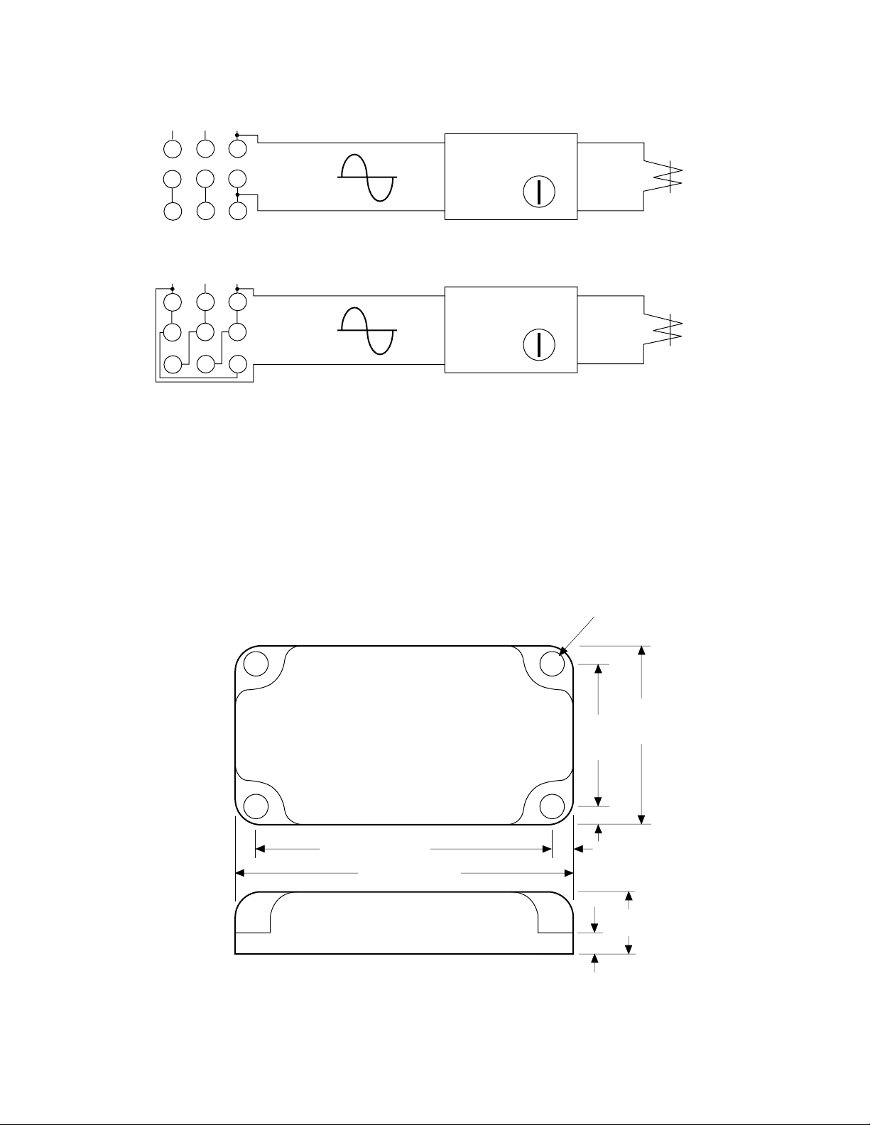
Dimensional Data
2.88" (73.2)
3.3" (83.8)
.190"
(5)
0.22" (5.59)
4 holes
2.2"
(55.9)
1.8"
(45.7)
.190"
(5)
0.56"(14.2)
(All Dimensions Nominal)
0.15"(3.81)
Figure 6
Warner Electric • 800-825-9050 P-239-36-WE • 819-0450 5
Page 6

Warranty
Warner Electric LLC warrants that it will repair or replace (whichever it deems advisable) any product
manufactured and sold by it which proves to be defective in material or workmanship within a period of one (1)
year from the date of original purchase for consumer, commercial or industrial use.
This warranty extends only to the original purchaser and is not transferable or assignable without Warner Electric
LLC’s prior consent.
Warranty service can be obtained in the U.S.A. by returning any defective product, transportation charges
prepaid, to the appropriate Warner Electric LLC factory. Additional warranty information may be obtained by
writing the Customer Satisfaction Department, Warner Electric LLC, 449 Gardner Street, South Beloit, Illinois
61080, or by calling 815-389-3771.
A purchase receipt or other proof of original purchase will be required before warranty service is rendered. If
found defective under the terms of this warranty, repair or replacement will be made, without charge, together
with a refund for transportation costs. If found not to be defective, you will be notified and, with your consent, the
item will be repaired or replaced and returned to you at your expense.
This warranty covers normal use and does not cover damage or defect which results from alteration, accident,
neglect, or improper installation, operation, or maintenance.
Some states do not allow limitation on how long an implied warranty lasts, so the above limitation may not apply
to you.
Warner Electric LLC’s obligation under this warranty is limited to the repair or replacement of the defective
product and in no event shall Warner Electric LLC be liable for consequential, indirect, or incidental damages of
any kind incurred by reason of the manufacture, sale or use of any defective product. Warner Electric LLC neither
assumes nor authorizes any other person to give any other warranty or to assume any other obligation or liability
on its behalf.
WITH RESPECT TO CONSUMER USE OF THE PRODUCT, ANY IMPLIED WARRANTIES WHICH THE
CONSUMER MAY HAVE ARE LIMITED IN DURATION TO ONE YEAR FROM THE DATE OF ORIGINAL
CONSUMER PURCHASE. WITH RESPECT TO COMMERCIAL AND INDUSTRIAL USES OF THE PRODUCT,
THE FOREGOING WARRANTY IS IN LIEU OF AND EXCLUDES ALL OTHER WARRANTIES, WHETHER
EXPRESSED OR IMPLIED BY OPERATION OF LAW OR OTHERWISE, INCLUDING, BUT NOT LIMITED TO,
ANY IMPLIED WARRANTIES OF MERCHANTABILITY OR FITNESS.
Some states do not allow the exclusion or limitation of incidental or consequential damages, so the above
limitation or exclusion may not apply to you. This warranty gives you specific legal rights and you may also have
other rights which vary from state to state.
Changes in Dimensions and Specications
All dimensions and specifications shown in Warner Electric catalogs are subject to change without notice.
Weights do not include weight of boxing for shipment. Certified prints will be furnished without charge on request
to Warner Electric.
www.warnerelectric.com
31 Industrial Park Road
New Hartford, CT 06057
815-389-3771
P-239-36-WE 819-0450 1/19
 Loading...