

Page 1
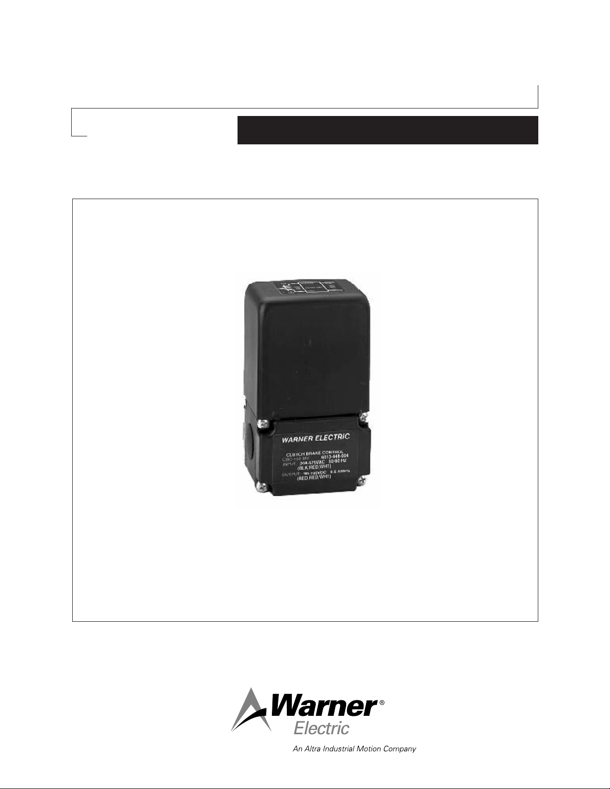
CBC-160-MV Fail Safe Brake
Multi-Voltage Control
P-239-34
819-0501
Installation & Operating Instructions
Page 2
Contents
Specifications
Indtroduction . . . . . . . . . . . . . . . . . . . . . . . . . . . . 2
Specifications. . . . . . . . . . . . . . . . . . . . . . . . . . . . 3
Warranty . . . . . . . . . . . . . . . . . . . . . . . . Back Page
Failure to follow these
instructions may result in product damage,
equipment damage, and serious or fatal injury
to personnel.
Introduction
The Warner Electric CBC-160MV is a family of
clutch/brake controls conveniently built into the
conduit box cover of the Elecctro Module line of
electromagnetic clutches and brakes. The CBC160MV control is a single channel device, that is
adjustable for precise operation of the brake, with
flexible adjustable for precise operation of the
brake, with flexible voltage input from 208 to 575
VAC. This control is designed for operation with
Warner Electric’s permanent Magnet 90VDC Fail
Safe Motor Brakes. It may also be used with any
Warner Electric 90VDC clutch/brake.
Input 208-575VAC, 50/60 Hz.
Output Range 30-100 VDC (adjustable). 0.5
amps
Fusing
(Optional) 1 amp, 250 V fast-blow
Ambient
Temperature0 to 122 F, (-18 to 50)C
Switching Supplied by Customer
Cycle Rate Consult Warner Electric’s Master
Catalog, form no. P-1000, for energy
dissipation of your application.
Set-Up The recommended settings for
Electro module Fail Safe Motor
Brakes are as follows.
To insure optimum release, it is factory set to
90VDC. Adjust the potentiometer on the control to
the required brake coil voltage as measured with a
voltmeter. The recommended voltage listed below
is based on nominal line voltage.
Model Voltage
UM - 50 70-100 volts DC
UM - 100 70-100 volts DC
UM - 180 90 volts DC
UM - 210 70-100 volts DC
UM - 215 70-100 volts DC
Reorder Information
Model Part Number
CBC-160-MV 6013-448-004
Warner Electric • 800-825-9050 819-0501
2
Page 3

Installation
BLK/RED
HOT
RED
BLK
NEUT
WHT
RED
CBC-160-MV
RED/WHT
90100
VDC
208575
VAC
+
-
LOGIC
DRIVER
2.74"
.6"
1.62"
1.62"
POWER SUPPLY
3.24"
WARNER ELECTRIC
CLUTCH BRAKE CONTROL
CBC-160-MV
6013-448-004
To avoid injury, always make certain all power is off before attempting to install
this control, or any electrical equipment.
1. Connect the red wire to the red wire of the
brake lead; connect the red/white wire to the
black wire of the brake.
2. Connect the black/red stripe wire to the hot
side of the AC, power source as indicated.
3. Connect the white wire to the neutral side of
the AC power.
4. Secure the conduit box control to the brake.
This is a floating type power
supply and is not referenced to AC ground.
Under no circumstance should any of the output wire leads be connected to earth or chassis ground as the unit will be destroyed.
Connection
Warner Electric • 800-825-9050 819-0501
3
Page 4

Warranty
Warner Electric LLC warrants that it will repair or replace (whichever it deems advisable) any
product manufactured and sold by it which proves to be defective in material or workmanship
within a period of one (1) year from the date of original purchase for consumer, commercial or
industrial use.
This warranty extends only to the original purchaser and is not transferable or assignable without
Warner Electric LLC’s prior consent.
Warranty service can be obtained in the U.S.A. by returning any defective product, transportation
charges prepaid, to the appropriate Warner Electric LLC factory. Additional warranty information
may be obtained by writing the Customer Satisfaction Department, Warner Electric LLC, 449
Gardner Street, South Beloit, Illinois 61080, or by calling 815-389-3771.
A purchase receipt or other proof of original purchase will be required before warranty service is
rendered. If found defective under the terms of this warranty, repair or replacement will be made,
without charge, together with a refund for transportation costs. If found not to be defective, you
will be notified and, with your consent, the item will be repaired or replaced and returned to you
at your expense.
This warranty covers normal use and does not cover damage or defect which results from
alteration, accident, neglect, or improper installation, operation, or maintenance.
Some states do not allow limitation on how long an implied warranty lasts, so the above limitation
may not apply to you.
Warner Electric LLC’s obligation under this warranty is limited to the repair or replacement of the
defective product and in no event shall Warner Electric LLC be liable for consequential, indirect,
or incidental damages of any kind incurred by reason of the manufacture, sale or use of any
defective product. Warner Electric LLC neither assumes nor authorizes any other person to give
any other warranty or to assume any other obligation or liability on its behalf.
WITH RESPECT TO CONSUMER USE OF THE PRODUCT, ANY IMPLIED WARRANTIES WHICH
THE CONSUMER MAY HAVE ARE LIMITED IN DURATION TO ONE YEAR FROM THE DATE OF
ORIGINAL CONSUMER PURCHASE. WITH RESPECT TO COMMERCIAL AND INDUSTRIAL
USES OF THE PRODUCT, THE FOREGOING WARRANTY IS IN LIEU OF AND EXCLUDES ALL
OTHER WARRANTIES, WHETHER EXPRESSED OR IMPLIED BY OPERATION OF LAW OR
OTHERWISE, INCLUDING, BUT NOT LIMITED TO, ANY IMPLIED WARRANTIES OF
MERCHANTABILITY OR FITNESS.
Some states do not allow the exclusion or limitation of incidental or consequential damages, so
the above limitation or exclusion may not apply to you. This warranty gives you specific legal
rights and you may also have other rights which vary from state to state.
Changes in Dimensions and Specifications
All dimensions and specifications shown in Warner Electric catalogs are subject to change without
notice. Weights do not include weight of boxing for shipment. Certified prints will be furnished
without charge on request to Warner Electric.
Warner Electric LLC
31 Industrial Park Road • New Hartford, CT 06057
815-389-3771
www.warnerelectric.com
• Fax: 815-389-2582
P-239-34 819-0501 6/12 Printed in USA
 Loading...