

Page 1
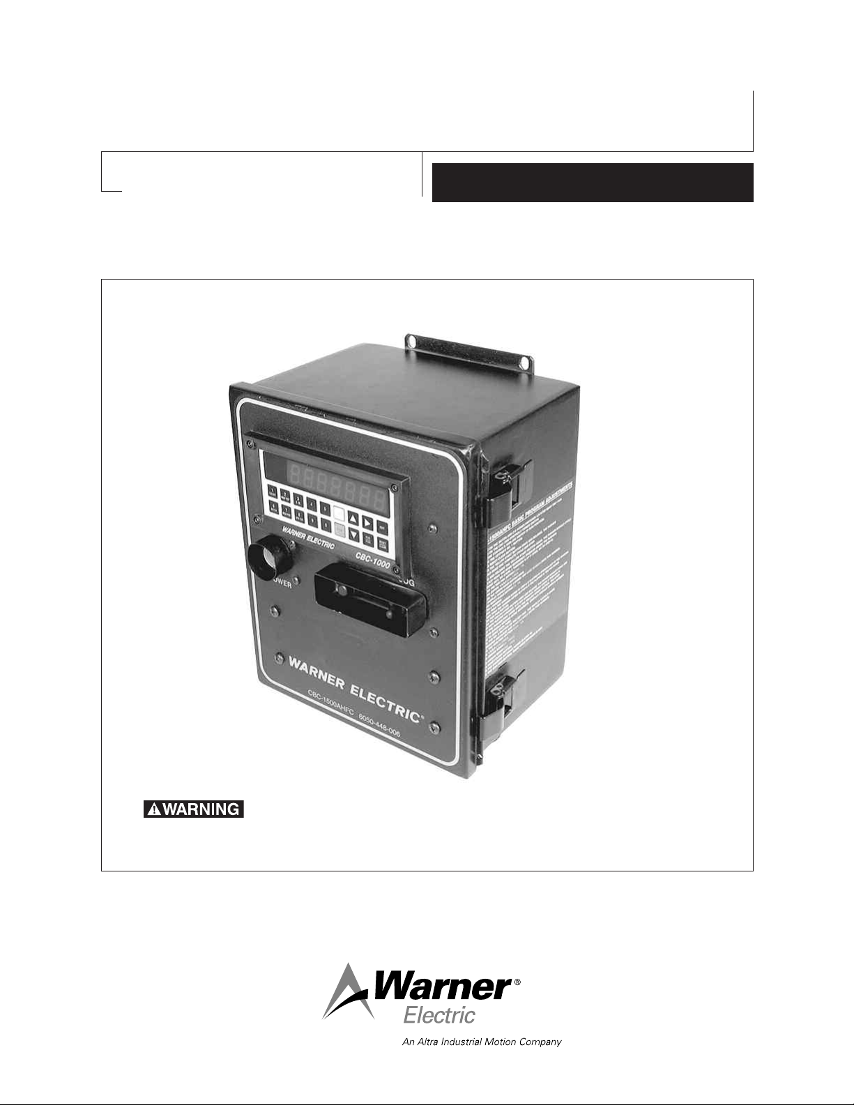
CBC-1500AHFC & 1550AHFC Closed Loop
Unidirectional Clutch/Brake Control System
P-291
819-9050
Installation Instructions
To prevent personal injury, ensure all personnel are clear of
conveyor line and the pusher before performing any adjustments on the
control.
Page 2

Contents
Introduction . . . . . . . . . . . . . . . . . . . . . . . . . . . . 2
Ordering Information . . . . . . . . . . . . . . . . . . . . . 3
Specifications . . . . . . . . . . . . . . . . . . . . . . . . . . . 3
Installation . . . . . . . . . . . . . . . . . . . . . . . . . . . . . 3
Connection Diagram CBC-1500 . . . . . . . . . . . . 4
Control Adjustments. . . . . . . . . . . . . . . . . . . . . . 4
Connection Diagram CBC-1550 . . . . . . . . . . . . 5
CBC-1000AH Operation. . . . . . . . . . . . . . . . . . . 6
Programming . . . . . . . . . . . . . . . . . . . . . . . . . . . 7
Failure to follow these instructions may result in product damage, equipment damage, and fatal injury to personnel.
Introduction
Warner Electric's CBC-1500AHFC and CBC1550AHFC are closed-loop positioning controls
designed with error compensation and autohome capabilities for industrial clutch/brake
applications. The position loop is closed through
encoder feedback which generates pulses proportional to load motion. The CBC-1500AHFC
and CBC-1550AHFC use this feedback to determine the optimum brake actuation point. The
autohome feature requires a marker input from
the encoder to find its user defined home position upon power up. The CBC-1500AHFC and
CBC-1550AHFC are a combination of a CBC-
Additional Features. . . . . . . . . . . . . . . . . . . . . . 13
CBC-1000AH Diagnostic Tests . . . . . . . . . . . . 14
Troubleshooting . . . . . . . . . . . . . . . . . . . . . . . . 15
Electrical Diagram . . . . . . . . . . . . . . . . . . . . . . 16
Dimensional Diagram . . . . . . . . . . . . . . . . . 17-18
Programming Adjustments . . . . . . . . . . . . . 19-20
Terminology . . . . . . . . . . . . . . . . . . . . . . . . . . . 21
Torque Adjustments . . . . . . . . . . . . . . . . . . . . . 21
Warranty . . . . . . . . . . . . . . . . . . . . . . Back Cover
1000AH and a CBC-500 or CBC-550, respectively, joined together in one package for a total
control solution (for more information on either
control refer to the Warner Electric Master
Catalog, P-1000). Dual channel torque adjustment is provided via on-board potentiometers
for accomplishing soft starts and stops. Each
unit operates in absolute mode where it maintains its position in an absolute sense and compensates for any slight errors made on the prior
move. The two outputs can be energized alternately or simultaneously and internal circuitry
provides suppression of transients during decay
of the magnetic field to assure rapid cycle rates.
Installation
The voltage present in this
control can cause serious injury (even death).
When installing the control or any electrical
equipment, make certain that the input
power is off. Do not apply power to this control until it is securely mounted and completely wired in accordance with local codes
and all installation work, including cleanup,
has been completed.
Warner Electric • 800-825-9050 819-9050
2
Page 3

Ordering Information
Model Number Part Number
CBC-1550AHFC Control 6050-448-008
CBC-1500AHFC Control 6050-448-006
Encoder Cable (Accessory) 6060-101-003
600 Pulse Per Revolution Encoder with Marker Pulse & 10' Cable 6060-101-061
RS-232 to RS-422/485 Converter (Accessory) 6060-101-232
Specifications
Input:
CBC-1500AHFC-90: 120 VAC ±10%, 50/60 Hz, 1 Phase, 300 VA max.
CBC-1000AH: Switch selectable AC power input to be 120 VAC only.
CBC-1550AHFC-24: 220 VAC ±10%, 50/60 Hz, 1 Phase, 300 VA max.
CBC-1000AH: Switch selectable AC power input to be 220 VAC only.
Programming Options (described on pages 6 through 8.)
Start input:
CBC-1500AHFC: 120 VAC
CBC-1550AHFC: 24 VAC
Output:
CBC-500-90: 0-90 VDC full-wave rectified nominal, 1.0 amp per channel max., 2.0 amps total.
CBC-550-24: 0-24 VDC full-wave rectified nominal, 4.0 amps per channel max, 4.0 amps total.
CBC-1000AH: Open collector active low outputs, 100mA sink max., 24 VDC max.
Circuit Protection: (fusing)
CBC-1500AHFC-90: 1.6 amps, 250 V fast blo
CBC-1550AHFC-24: 3 amps, 250 V fast blo
CBC-500-90: 2.5 amps, 250 V fast blo, 3AG
CBC-550-24: 5 amps, 250 V fast blo, 3AG
Encoder:
600 ppr with marker pulse.
Adjustments:
CBC-500-90 and CBC-500-24:
Channel 1 Voltage (via potentiometer)
Channel 2 Voltage (via potentiometer)
Jumper (selects simultaneous or alternate mode)
Frequency Adjustment: 60-400 Hz (via potentiometer)
CBC-1500AHFC and CBC-1550AHFC:
Run/Jog Switch
Clutch Jog push button
Ambient Temperature:
-20° to 122°F (-29° to 50°C)
Auxiliary Supply:
CBC-500-90 and CBC-500-24
12 VDC, 250 mA maximum
Warner Electric • 800-825-9050 819-9050
3
Page 4
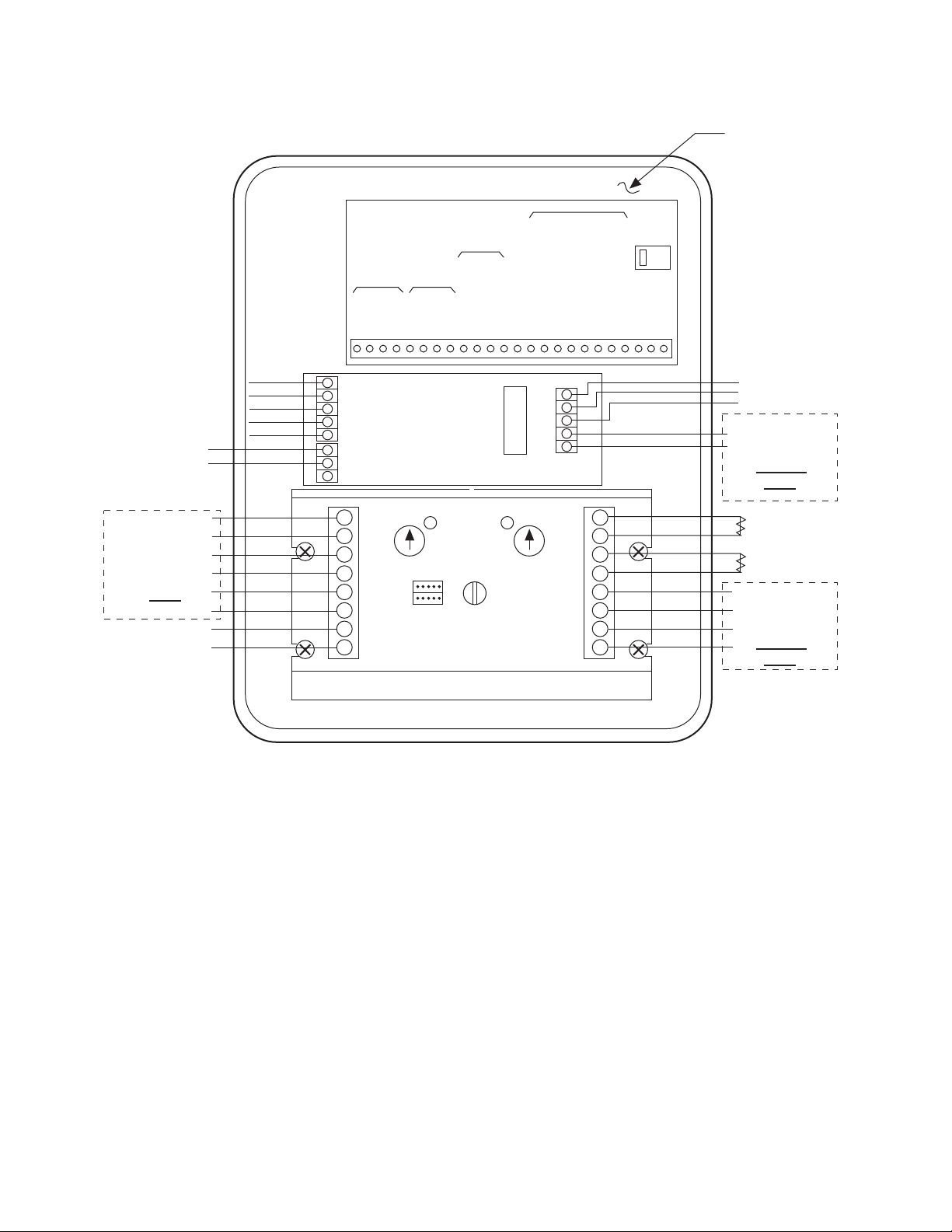
Connection Diagram CBC-1500AHFC
1 2345 6789101112131415161718192021222324
RED (+12v)
BRN (SIG A)
ORN (SIG B)
BLK (COM)
GRN (SIG Z)
120 VAC
Start Input
TB2
TB1
120 VAC Input Power
EARTH GROUND
NEUTRAL
HOT
+
_
1.6A, 250v
FUSE
ENCODER
INPUTS
RXD -
RXD +
TXD -
TXD +
+12v
SIG A
SIG B
COM
START
STOP
MARKER/SIG Z
RESET
COM
START
EARLY WARNING
BRAKE ON
ZERO SPEED
ZERO SPEED + DELAY 1
ZERO SPEED + DELAY 2
AUX START
BATCH COMPLETE
HOT
NEUTRAL
BLD. GND.
SERIAL
DATA
SIGNAL
INPUTS
CBC-1000AH
VAC
120
Back side of cover
CONTROL OUTPUTS
CONTROL
INPUTS
1
2
3
4
5
6
7
8
8
7
6
5
4
3
2
1
CHANNEL 1
(Brake)
CHANNEL 2
(Clutch)
CBC-500-90
FAC TORY
CONNECTIONS
See Page 17
DO NOT
USE
Auxilary
Supply
+12VDC, 250mA
+
_
+
_
+
_
(CHANNEL 2
LED)
(CHANNEL1
LED)
(CHANNEL 2
ADJUST)
(CHANNEL 1
ADJUST)
(FREQUENCY
ADJUST)
DUAL
SINGLE
(JUMPER)
FAC TORY
CONNECTIONS
See Page 17
FAC TORY
CONNECTIONS
DO NOT
USE
DO NOT
USE
Control Adjustments
CBC-500-90 and CBC-550-24:
Channel 1 and Channel 2 Torque
Adjustments:
Provides adjustment from 0 to full rated voltage.
Jumper: Allows operation of alternate or simultaneous mode. In the single mode, Channel 1
and Channel 2 function alternately. In the dual
mode, Channel 1 and Channel 2 function simultaneously. This mode will be employed in applications with a clutch and failsafe brake.
Frequency Adjustment: Provides adjustment of
60 to 400 HZ to reduce the clutch/brake "hum"
associated with machine frequencies.
CBC-1000AH:
Switch Selectable AC Input: Allows for choice
of inputting 120 VAC or 240 VAC to unit.
Programming Options: Described on the following pages.
CBC-1500AHFC and CBC-1550AHFC:
Run/Jog Switch: Allows operation in run or jog
mode. In run mode the unit will use the motion
profile programmed and cycle continuously until
interrupted. In jog mode the clutch can be
jogged using the clutch jog push button
described below.
Clutch Jog Push Button: Causes clutch to
rotate when push button is pressed.
Warner Electric • 800-825-9050 819-9050
4
Page 5
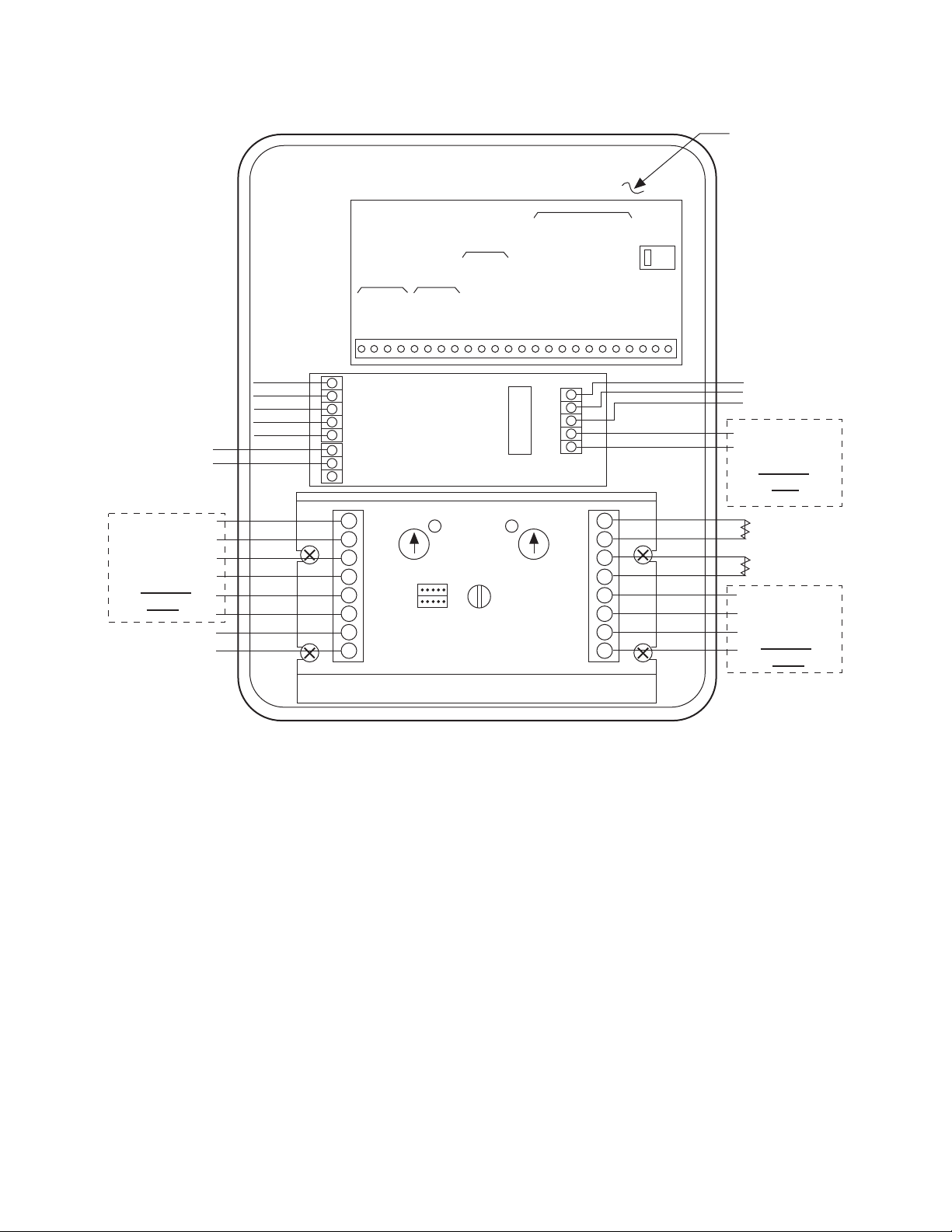
Connection Diagram CBC-1550
1 2345 6789101112131415161718192021222324
RED (+12v)
BRN (SIG A)
ORN (SIG B)
BLK (COM)
GRN (SIG Z)
24 VDC
Start Input
TB2
TB1
240 VAC Input Power
EARTH GROUND
NEUTRAL
HOT
+
_
3A, 250v
FUSE
ENCODER
INPUTS
RXD -
RXD +
TXD -
TXD +
+12v
SIG A
SIG B
COM
START
STOP
MARKER/SIG Z
RESET
COM
START
EARLY WARNING
BRAKE ON
ZERO SPEED
ZERO SPEED + DELAY 1
ZERO SPEED + DELAY 2
AUX START
BATCH COMPLETE
HOT
NEUTRAL
BLD. GND.
SERIAL
DATA
SIGNAL
INPUTS
CBC-1000AH
VAC
230
Back side of cover
CONTROL OUTPUTS
CONTROL
INPUTS
1
2
3
4
5
6
7
8
8
7
6
5
4
3
2
1
CHANNEL 1
(Brake)
CHANNEL 2
(Clutch)
CBC-550-24
FACTORY
CONNECTIONS
See Page 17
DO NOT
USE
Auxilary
Supply
+12VDC, 250mA
+
_
+
_
+
_
(CHANNEL 2
LED)
(CHANNEL 1
LED)
(CHANNEL 2
ADJUST)
(CHANNEL 1
ADJUST)
(FREQUENCY
ADJUST)
DUAL
SINGLE
(JUMPER)
FACTORY
CONNECTIONS
See Page 17
DO NOT
USE
FAC TORY
CONNECTIONS
DO NOT
USE
5
Page 6

CBC-1000AH Control Operation
1
COUNT
2
MOV PST
3
E.W.
6
BATCH
7
BCH PST
8
BRK DIS
Successful operation will require knowledge of the following definitions and their relationships to the
Timing Diagram below.
Function Key Definitions
Count The actual move distance, in pulses or scaled into engineering units
(inches, feet, rotations, degrees, etc.), displayed dynamically.
Move Preset The desired move distance in pulses or scaled into engineering units.
This is the value the operator enters to select a new move distance. It
can also be locked during the RUN mode by simply programming line
6 to "off".
Early Warning A distance prior to Move Preset at which the early warning output is
activated. Expressed as pulses or engineering units, this output can
be used to accomplish a soft brake (slow down), energize valves, etc.
Batch* A cumulative batch counter that can be dynamically displayed to show
the number of operations, cycles, etc. When this counter reaches the
value programmed by the Batch Preset (key 7) the Batch Complete
Output (pin 21 on CBC-1000) is activated. The batch counter can be
manually or automatically reset.
Batch Preset* A programmable batch counter activates the batch complete output
when the value programmed has been reached by the batch (key 6).
Braking Distance The actual distance required to stop. This value is dynamically updat-
ed to determine the brake actuation point. Factory default is 25 pulses or engineering units which is only used for the first cycle after
power-up. After the first cycle the CBC-1000 will tune to the particular
brake being utilized. The amount of cycles needed for tuning depends
on how far the true braking distance value is from the default of 25.
* The batch counter is not factory enabled. To utilize, see "Additional Features" section.
Warner Electric • 800-825-9050 819-9050
6
Page 7

Programming
1
COUNT
2
MOV PST
3
E.W.6BATCH
7
BCH PST
8
BRK DIS
2
MOV PST
EDIT
RESET
CLEAR
EDIT
2
MOV PST
EDIT
EDIT
7
BCH PST
EDIT
RESET
CLEAR
EDIT
6
BATCH
RESET
CLEAR
1
COUNT
RESET
CLEAR
View Presets and Values
The six function keys may all be viewed during the RUN mode. To view their values, press the desired
function key and the value is displayed with the corresponding display annunciator. The controller
process continues without interruption.
Press to display the current length or position (up to six digits).
Press to display the move preset (up to six digits).
Press to display the early warning preset (up to four digits).
Press to display the batch counter (up to six digits).
Press to display the batch counter preset (up to six digits).
Press to display the average braking distance (up to four digits).
Entering Presets
The three presets (MOV PST, E.W., and BCH PST) may also be changed during the RUN mode provided that programming line 7 (panel lock) is programmed "off". To edit, press the desired preset function
key, next press the EDIT key followed by the CLEAR key. Enter the new value using the numeric keys,
then press the EDIT key to exit the edit mode and to replace the existing value in memory. The CBC1000 will use the new number entered after the edit mode is exited.
Move
Preset Press , then press , and press , now enter a new value using the numeric keys,
then press
or Press , then press , and press or to change the value incrementally, Then press
Batch
Preset Press ,then press , and press , now enter a new value using the numeric keys,
then press
Batch
Counter To manually reset the batch counter: Press , then press
Reset
System
Home To home the system: Press , then press
7
Page 8

Six Simple Setup Steps:
RUN
PGM
1
COUNT
0
0
0
EDIT
RUN
PGM
After encoder, clutch/brake, and power connections are made per one of the connection diagrams found on pages 4 and 5:
1. Apply power to unit and move to home posi-
tion (can use JOG switch). When at home,
reset counter to zero.
4. Press the RUN/PGM key to get back to RUN
Mode and out of Program Mode. Enter in the
Move Preset (MOV PST) value, key 2 (refer to
page 6 for instructions on Entering presets).
Due to the auto-home feature, the Move Preset
must be equal to one revolution of the encoder
(600 pulses). The display can be scaled to display any engineering units.
2. Find home reference number by rotating
machine by hand or by jogging and noting
the number that is displayed when the 'ref'
light on the left/bottom of the display is illuminated. Program this number in memory by
entering Program Mode outlined below and
inserting number on line 1 (h. ). It might
take a few tries before you can accurately
catch the number on the display when the
'ref' light illuminates.
No outputs will fire until the
home reference number is programmed in.
Unit is ready to cycle!
5. After cycling approximately ten times, observe
the actual braking distance number (BRK DIS,
key 8). Enter the programming mode and place
this number in line 2 (bd, initial braking distance). This will ensure that, on power up, the
system will take the minimum number of cycles
to find home. Check the early warning number
entered and make sure that it occurs before
the brake output is activated. Also, the home
reference number programmed in line 1 must
occur before the early warning and brake outputs. If this is not the case, the encoder must
3. While in Program Mode you will need to turn
on Auto Reset, which is line 9. The default
can be toggled by pressing the right arrow
button. This feature will reset the counter to
zero after every cycle.
be rotated without the machine being rotated
to change where the marker pulse occurs.
Otherwise, the marker pulse will not be detected because it will occur after the brake has
been energized.
Program Mode
To enter the program mode to access the 34 features shown on pages 12 and 13, press the program
key and enter the 4-digit password (1000) followed by the down cursor. Note: Before entering the program mode, the stop key or stop input should be activated. The CBC-1000 automatically activates the
brake upon entry into the program mode.
To enter the program mode:
Press , then press , then press
Move down one program line
or press , then press line number, and press to jump to the line changing
Move up one program line
Select Options
To exit the program: Press
Warner Electric • 800-825-9050 819-9050
8
Page 9

Programming
Line Display Description Options Default Program
1 h. Home Reference Number — — — — 0
2 bd. Initial Braking Distance — — — — 25
3 bd.AuE. # of Cycles Averaged 1 - 9 3
4 cc. Correction Constant — — — — –– 0.5000
5 dP. Decimal Point off, .0, .00, .000 oFF
6 FrSt. Front Panel Reset on - off on
7 PLoc. Front Panel Lock on - off oFF
8 CrEt. Count Retention on - off oFF
9 ArSt. AUTO Reset on - off on
10 ol. Start Output 00.00 to 99.99 00.20
11 o2. Early Warning Output 00.00 to 99.99 00.01
12 o3. Brake on Output 00.00 to 99.99 00.20
13 o4. Zero Speed Output 00.00 to 99.99 00.10
14 o5. Zero Speed + Delay 1 00.00 to 99.99 00.05
15 o6. Zero Speed + Delay 2 00.00 to 99.99 00.05
16 o8. Batch Counter Reset 00.00 to 99.99 LATCH
17 dl. Delay Time 1 00.00 to 99.99 00.10
18 d2. Delay Time 2 00.00 to 99.99 00.01
19 05P. Zero Speed Window .01, .05, .10, .25 sec. .25
20 5 Start Command Release Outputs .no change __ __ __ __ __ __
1-6 d .drop out . . . . .
21 L Move Preset Release Outputs . no change __ __ __ __ __ __
1-6 d .drop out . . . . .
22 E Early Warning Release Outputs . no change __ __ __ __ __ __
1-6 d .drop out . . . . .
23 r Reset Command Release Outputs . no change __ __ __ __ __ __
1-6 d .drop out . . . . .
24 br. Baud rate off, 300, 600, 900 oFF
1200, 2400
25 PAr Parity nonE, odd, EuEn nonE
26 id.no. Identification Number 0 - 99 0
27 t0. Keyboard Test rdy y
28 tl. Non-Volatile RAM Test Press y
29 t2 Input Test Ab - encoder inputs
1 - start
2 - stop y
3 - cont. 4 reset
30 t3 Output Test 1 - E y
31 t4 Display Test Press y
32 t5 Program Memory Test Press y
33 t6 Date Code Test Press y
34 t7 Serial Test Press y
35 t8 Factory Default Settings Press y
Refer to
Diagnostics
Test Page 9
9
Page 10

Programming
RESET
CLEAR
Line
1 The number that is downloaded to the display when the marker pulse is detected.
2 The first brake distance used by the CBC-1000 at power-up.
3 The number of cycles used for the running average of brake distance.
4 The scaling factor for the front panel display (0.5000 for display in pulses).
5 Number of decimal points displayed. Affects all distance values in other registers.
6 Enables or disables front panel reset in the Run Mode.
7 "On" enables and "Off" disables changing MOV PST, E.W., and BCH PST while running.
8 Retains system position during power off.
9 Select Absolute (ON) or Incremental (OFF) mode of operation.
10 The duration (momentary or latched) of the Start Output in seconds.
For latched input, enter all zeros or press
11 The duration (momentary or latched) of the Early Warning output in seconds.
12 The duration (momentary or latched) of the Brake On output in seconds.
13 The duration (momentary or latched) of the Zero Speed output in seconds.
14 The duration (momentary or latched) of the Zero Speed + Delay 1 output in seconds.
15 The duration (momentary or latched) of the Zero Speed + Delay 2 output in seconds.
16 Momentary for automatic (internal) reset or latched for manual (operator) reset.
17 The delay time for Zero Speed + Delay 1 output in seconds.
18 The delay time for Zero Speed + Delay 2 output in seconds.
19 The time window in seconds to determine Zero Speed. Zero Speed equals no pulses received within window.
20 Releases latched outputs at the start command. Press 1-6 on the front panel to release or drop output.
21 Releases latched outputs at the move preset. Press 1-6 on the front panel to release output or drop output.
22 Releases latched outputs at the Early Warning signal. Press 1-6 on the front panel to release output or drop
output.
23 Releases latched outputs at reset. Press 1-6 on the front panel to release output or drop output.
24 See Serial Interface section.
25 See Serial Interface section.
26 Control identification number. See Serial Interface section.
See Diagnostic Tests on page 15 for further information on diagnostic tests listed below.
27 Front panel keyboard test.
28 Non-Volatile RAM test.
29 Control input test.
30 Control output test.
31 Front panel display test.
32 Control program memory test.
33 Displays Date Code of CBC-1000 software.
34 Control serial test.
35 Returns control to factory default settings.
Warner Electric • 800-825-9050 819-9050
10
Page 11

CBC-1500AHFC and CBC-1550AHFC Program for Fast Cycling Feature
Line Program
1 275
2 25
33
4 0.5
5 OFF
6 ON
7 OFF
8 OFF
9 ON
10 0.1
11 0.01
12 0.1
13 0.07
14 0.05
15 0.05
16 LATCH
17 0.1
18 0.01
19 0.05
20 -.-.-.-.-.-.
21 -.-.-.-.-.-.
22 -.-.-.-.-.-.
23 -.-.-.-.-.-.
24 OFF
25 NONE
26 0
27 Y
28 Y
29 Y
30 Y
31 Y
32 Y
33 Y
34 Y
35 Y
Function Key Program
Count USER CAN'T EDIT
Move Preset 600
Early Warning 0
Batch XX Does not Matter
Batch Preset XX Does not Matter
Braking Distance USER CAN'T EDIT
11
Page 12

CBC1000
CBC1000
COUNT
CBC150 0 AHF C
CBC150 0 AHF C
COUNT
START
INPUT
START
OUTPUT
STOP
OUTPUT
ZERO SPEED
OUTPUT
ENCODER
MARK
E312
H915
13
F
C
B
D
3
2
6
4
7
A
G
1
8
11
10
14
CBC1500AHFC and CBC1550AHFC
Normal Cycle:
A) Brake is engaged.
B) The CBC1500AHFC receives a “start input’
from external control.
C) The CBC1500AHFC sends a “start output”
that turns on the clutch.
D) The encoder starts rotating and display
starts counting positive numbers. If display
counts negative numbers, swap encoder
inputs Sig. A and Sig. B.
E) The CBC1500AHFC receives an “encoder
index mark” and matches the “CBC1000
count” with the system count
(CBC1500AHFC count). The “CBC1000
count” goes back to the home reference
preset number.
F) When the “CBC1500AHFC count” is equal
to (600 minus the braking distance), the
CBC1500AHFC sends a “stop output,”
which turns on the brake. The system will
have a soft stop. The torque of the brake
can be adjust via potentiometer on the
CBCSOO control.
G) System arrives to a complete stop at 600
pulses.
H) When the encoder stops turning, the
CBC1000 sends a “zero speed” output to
the microcontroller.
8) The CBC1000 stops counting. The display
will stop counting for a short period of time.
9) After .05 seconds, CBC 1000 sends a “zero
speed” output to the microcontroller.
10) The microcontroller enables the encoder
input to the CBC1000.
11) The CBC1000 starts counting. AT THIS
POINT THE CBC1000 COUNT DOES NOT
MATCH THE SYSTEM’S COUNT. THE DISPLAY COUNT DOES NOT MATCH THE
SYSTEM COUNT.
12) The CBC1500AHFC receives an “encoder
index mark” and matches the “CBC1000
count” with the system count
(CBC1500AHFC count). The “CBC1000
count goes back to the home reference preset number. After the display changes, the
CBC1500AHFC will be capable to receive a
new “start input.” That is why the encoder
needs to be placed with the encoder mark
on the first 90 degrees of system rotation.
13) When the “CBC1500AHFC count” is equal
to (600 minus the braking distance), the
CBC1500OOAHFC sends a “stop output,”
which turns on the brake. The system will
have a soft stop. The torque of the brake
can be adjusted via potentiometer on the
CBC500 control.
14) The system arrives to a complete stop at
600 pulses.
Fast cycle:
1) Brake is engaged.
2) The CBC1500AHFC receives a “start input"
15) When the encoder stops turning, the
CBC1000 sends a “zero speed” output to
the microcontroller.
from external control.
3) The CBC1500AHFC sends a “start
output” that turns on the clutch.
4) The encoder starts rotating and display starts counting positive numbers. If display counts negative numbers, swap encoder inputs Sig. A
and Sig. B.
5) The CBC1500AHFC receives the
“encoder index mark” and matches
the CBC1000 count with the
CBC1500AHFC count.
6) The CBC1500AHFC receives a second “start input” from external control.
7) When the CBC1500AHFC count
arrives to 600, microcontroller disables the encoder input to the
CBC1000.
Warner Electric • 800-825-9050 819-9050
12
Page 13

Additional Features
These features are available on the current unit,
but some extra hardware or programming is
needed to enable them.
Batch Counter:
This feature will trigger the Batch Complete output, pin 21, when the Batch Preset, key 7,
reaches the Batch Counter, key 6, value (refer to
Entering presets, page 6, to enter a value in the
Batch Preset). The Batch Counter can be manually or automatically reset. Manual reset is the
default setting in the program mode line 16 (08.
latch). To automatically reset the Batch Counter,
set the Batch Counter Reset line 16 in Program
Mode to Momentary (00.01 to 99.99 seconds).
This will hold the Batch complete output terminal 21 active for the time programmed and reset
the Batch Counter.
E-Stop:
By maintaining a contact closure between COM,
terminal 13 and Stop terminal 10, no inputs will
be received or outputs fired. This can be used
as a safety feature to make sure a start will not
occur while some other process is taking place.
Display Scaling (Program Line 4)
• Changing the CC & decimal point will
affect presets
• CC should not exceed 1.0
• CC of .5 displays encoder pulses
The display can be easily scaled to display engineering units (inches, meters, degrees, rotations,
etc). Line 4 of the programming (correction constant) prompts input of a factor (five decades)
that will be multiplied times the incoming pulse
train to display the desired engineering units.
Remember that the CBC-1000 includes a times
2 internal multiplier effectively doubling the resolution of a given encoder. Thus, if one wishes to
view encoder pulses, a multiplier (correction
constant) of '0.5' should be entered on Line 4 in
the programming mode. The resolution of the
encoder should be chosen to take advantage of
the best instantaneous accuracy of the calibrator. The best instantaneous accuracy is obtained
with a correction constant setting not exceeding
1.0000. The scaled units are also used to measure stop and move distances. Consequently, the
scaled units selected affect the system resolution. For example, with the correction constant
set for display at 1.0 inches, is the smallest
measurable increment. Remember, the decimal
point must be programmed ( programming line
5) to display the desired display resolution. This
resolution is also used in the denominator of the
correction constant equation. The general form
of the equation for the correction constant is
given below.
CC (Correction Constant) =
Example: Web measurement - Display in inches, display resolution in tenths of an inch
Encoder Resolution - 600 PPR
Mounting - Direct, via 4" diameter wheel
Calculation:
cc = = 0.1047
0.1 x 600 pulses/revolution x 2
Distance traveled in engineering units per one revolution of the encoder
Display Resolution Desired x Encoder Resolution x 2
(0.001, 0.01, 0.1, 1.0)
2πr = (2)(π)(2) = 12.5664
13
Page 14

CBC-1000 Diagnostic Tests
RUN
PGM
t0: Keyboard Test: Tests the function of the front panel keys.
Press to begin test. RUN: will be displayed. Press each front panel key except to test key.
The display will indicate if the key is functional.
t1: Non-Volatile RAM Test: Tests CBC-1000 RAM.
Press to begin test. The test will return PASS or FAIL. Press to continue.
t2: Input Test: Tests whether CBC-1000 is accepting inputs.
Press to begin test. Activate inputs to control. If the input is received, a character will be displayed.
"Ab" - Encoder input, "1" - Start, "2" - Stop, "3" Continuous mode, "4" Reset. Press to continue.
t3: Output Test: Used to determine whether CBC-1000 outputs are functional.
Press to begin test. Press keys 1-6 on the front panel. The corresponding output will turn on and
latch. Use a VOM to check for a high level state on terminal strip of CBC-1000. Press to exit test.
t4: Display Test: Tests function of each LED on front panel.
Press to begin test. Each digit of front panel display will automatically be turned on. Check for
faulty LEDs. Press to continue.
t5: Program Memory Test: Tests program memory capability.
Press to begin test. PASS or FAIL will be returned. Press to continue.
t6: Date Code Test: Displays software date code.
Press to display date code. Press to exit. Continue
t7: Serial Test: Tests connections with serial data interface module.
Press to begin test. PASS or FAIL will be displayed. Press to continue.
t8: Factory Default Settings: Returns CBC-1000 to factory settings.
Press to return all program steps to factory default settings.
Warner Electric • 800-825-9050 819-9050
14
Page 15

RESET
CLEAR
RESET
CLEAR
RESET
CLEAR
RESET
CLEAR
Troubleshooting
Problem Solution
Machine starts but does not stop • Establish a move Preset
• Ensure brake functions properly using output test.
Machine stops out of position • Make sure the marker pulse is detected before brake outputs fire.
Display counts backwards • Reverse Encoder A, B, wiring.
Machine stops abruptly, not a soft stop • Turn down torque adjust potentiometer for Channel 1.
Machine stops but then restarts • Control may be responding to a start command. Check for
transient signals. Use the E-Stop feature described in "Additional
Features" to disable a start input.
Control appears to function perfectly but the actual • Check for slippage between the encoder and the manual items.
error is greater then the display indicates.
Display not counting • Check encoder connections. If good connections exist, send
encoder for repair.
Control accumulates too many counts. Home or • Check Display Scaling, page 10, and check for electrical noise,
zero position is drifting. such as ground loops. Eliminate noise.
Control appears to work but proper motion is • Review Clutch Brake and Control Service Manuals.
not occurring. Use Output Test (line 30) to verify performance.
System does not operate and fails diagnostic • Return unit for repair, call an Authorized Warner Electric
Tests 1,3, 4, 5 or 7. Reference page 15. Distributor.
System stops, but does not fire outputs. • Lower zero speed window (line 19) to minimize effects of
encoder "bounce" caused by vibrations.
'Ref' light not illuminating every cycle. • A lower resolution encoder may be needed. Call factory for more
information.
Error Codes
If an error message appears • Disconnect power to CBC-1000 momentarily and error should
clear. Press to clear error code.
Error Code 2 - Low Line Voltage. • Correct line voltage. Press to clear error code.
Error Code 3 - Feedback too fast. • Reduce encoder resolution and/or speed to keep encoder feed-
back less than 20,000 PPS. Press to clear error code.
Error Code 4 - Process Time fully utilized • Reduce encoder resolution or consult factory. Press to
clear error code.
Warner Electric • 800-825-9050 819-9050
15
Page 16

Electrical Diagram
1 2
3
4
5 6
7
8 9
10 11
12
13 14 15 16 17 1819 20
21 22
23
24
1 2 3 4 5
6 7
8 9
10
11
12
13
1
2 3 4 5 6
1
2 3 4 5 6
1
2
3
4
5
EGND
NEUT
HOT
RED
BLACK
TB1
F U S E
J3
1
2
3
4
5
6
7
8
CBC-500-90 or CBC-550-24
1
2
3
4
5
6
POWER SWITCH
CBC-1000AH TERMINAL
P. C .
BOARD ASSY.
J4
J5
N.C.
TERMINAL BLOCK
ON CBC-550-24
TRANSFORMER
TB2
1
2
3
4
5
6
7
8
+12V
SIG A
SIG B
COM
REF
HOT
NEUT
EGND
N.C.
N.C.
CBC-1500AHFC
500-90
HOOK-UP
ONLY
CBC-1500AHFC
500-24
HOOK-UP
ONLY
1
2
3
4
5
6
7
8
A/C FILTER
Warner Electric • 800-825-9050 819-9050
16
Page 17
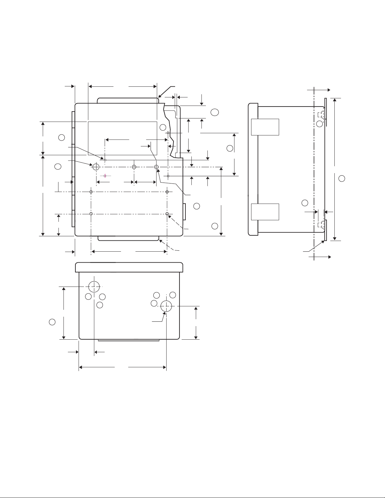
Dimensional Diagram
DS
E1
DS
E1
D3
C1
E3
F
F
1.250
1.25
0.700
±.005
.500 Ø
2 PLCS
NOTE 3
.15
.935
1.75
1.57
.910ø
.164ø
4 PLCS
E2
1.00
1.75
1.26
NOTE 3
.218 Ø
4 PLCS
C1
H1
.87 ø
2. PLCS
1.25
G
G
G1
G1
A
H
5.43
5.000
3.00
6.36
2.68
1.50
6.00
2.75
3.200
5.40
3.00
6.75
3.62
A
0.44
NOTE 3
2 PLCS.
11.00
Warner Electric • 800-825-9050 819-9050
17
Page 18
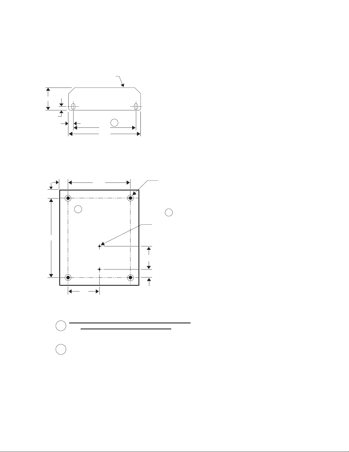
Dimensional Diagram
G1
4.75
4.13
.31
.25
1.50
NOTE 3 (REF)
H
J
6.250
0.870
0.870
8.250
3.12
0.75
2.375
10-32 WELD NUTS 4PLCS
10-32 TH'D TO BE FREE
OF PAINT 4 PLCS
DRILL T HRU ø0.136
T
HEN TAP 8 -32
2 PLCS
8-32 TH 'D TO B E FR EE
OF PAINT 2 PLCS
SECTION A-A
1.) WELD NUTS 4 PLACES AS SHOWN OHIO NUT
& BOLT CO. P/N WF 1405 OR EQUIV.
2.) ENCLOSURE TO BE 10X8X6 SIMILAR TO HOTTMAN P/N
A-10086CH W/COLOR BLACK POLY POWDER COAT.
3.) ENLARGE FOUR MOUNTING SLOTS FROM .22X.28LG TO .25X.375LG.
D2
D4
Warner Electric • 800-825-9050 819-9050
18
Page 19

CBC1500AHFC and CBC1550AHFC Revision B Installation Procedure
To prevent personal injury, ensure all personnel are clear of conveyor line and the
pusher before performing any adjustments on the control.
Programming Adjustments
1. Turn on the power switch of the control. The power switch should illuminate.
2. On the control display, press #2 (MOV-PST). The number 600 should be displayed on the LED display.
If any other number is displayed, do the following:
a) Press “EDIT” (the word edit should be displayed on the LED display).
b) Press “CLEAR” (all numbers should reset to zero).
c) Enter 600.
d) Press “EDIT” (the word edit should turn off).
3. Press #1 (COUNT) on the control.
4. Set the toggle switch on the control marked RUN/JOG to JOG position.
5. Press the “CLUTCH-JOG” switch and release immediately. Make sure the pusher is moving in the right
direction for its configuration. If not, remove power from the system (including power from the motor) and
swap the motor phase wires.
Note: I f t he cont r ol i s count i ng negat i ve number s, swap Si gnal A and Si gnal B i nput s
i n t he War ner El ect r i c cont r ol .
6. Jog pusher until the long arm is straight and both paddles are inside the pusher enclosure.
7. Press #1 (COUNT) on the control.
8. Press “CLEAR” (all numbers should reset to zero).
9. Jog the pusher slowly as you watch the lower left side of the display. When you see “ref” light come on,
stop and note what number is in the display. This is your “home reference”. The “home reference” will have
to be entered into the control in a later step.
Note: The “ r ef ” l i ght mus t be seen bet ween 100 and 500 pul s es. I f t he “ r ef ” s i gnal
i s not seen unt i l bey ond t hi s r ange, t he encoder wi l l have t o be di smount ed r ot at ed
l ef t or r i ght 90 degr ees and r emount ed. Once t he encoder has been r emount ed r epeat
st ep #9.
10. On the control display, press “RUN/PGM”.
11. Enter 1000.
12. Press the down arrow.
13. The first line of the program should be displayed, showing the home reference “h” and a value (this value
could be zero).
14. Press “CLEAR”.
15. Enter the “home reference” you recorded in step #9.
16. Press the arrow down key. bd (25 to 75) Braking distance average
If it is not in that range:
Press “RESET/CLEAR” bd 0 Clearing to set new value
Press key 6. bd 60 Braking set: 60 encoder pulses
17. Press the arrow down key. bd. AuE. 3 Number of cycles averaged = 3
18. Press the arrow down key. cc. 0.5000 Count Correction Feature
19. Press the arrow down key. dP. off Decimal Point Feature is off.
20. Press the arrow down key. FrSt. on Front panel reset is enabled.
21. Press the arrow down key. PLoc. off Front panel lockout is off.
22. Press the arrow down key. CrEt. off Count retention should be off.
If it says CrEt on:
Press the arrow right key. CrEt. off Count retention is now back off.
23. Press the arrow down key. ArSt. on Auto reset should be on.
If it says ArSt. Off:
Press the arrow right key. ArSt. on Auto reset is now back on.
24. Press the arrow down key. 01 00.20 Start signal of 200ms.
If it is not 00.20:
Press “RESET/CLEAR” 01 LAtch
Press key 2. 01 00.02
Warner Electric • 800-825-9050 819-9050
19
Page 20

Press key 0. 01 00.20
25. Press the arrow down key. 02 00.01 Early warning signal, not used.
If it is not 00.01:
Press “RESET/CLEAR” 02 LAtch
Press key 1. 02 00.01
26. Press the arrow down key. 03 00.20 Stop signal of 200ms.
If it is not 00.20:
Press “RESET/CLEAR: 03 LAtch
Press key 2. 03 00.02
Press key 0. 03 00.20
27. Press the arrow down key. 04 00.10 Zero speed signal of 100ms.
If it is not 00.10:
Press “RESET/CLEAR” 04 LAtch
Press key 1. 04 00.01
Press key 0. 04 00.10
28. Press the arrow down key. 05 00.05 Zero speed signal plus 50ms.
If it is not 00.05:
Press “RESET/CLEAR” 05 LAtch
Press key 5. 05 00.05
29. Press the arrow down key. 06 00.05 Zero speed plus second 50ms.
If it is not 00.05:
Press “RESET/CLEAR” 06 LAtch
Press key 5. 06 00.05
30. Press the arrow down key. 08 LAtch Batch counter auto reset
31. Press the arrow down key d1 0.10 Zero speed delay #1
If it is not 0.10:
Press “RESET/CLEAR” d1 0.00
Press key 1. d1 0.01
Press key 0. d1 0.10
32. Press the arrow down key. d2 0.01 Zero speed delay #2.
If it is not 0.01:
Press “RESET/CLEAR” d2 0.00
Press key 1. d2 0.01
33. Press the arrow down key. 05P .25 Zero speed window of 250ms
If it is not .25:
Press the arrow right key. 05P .25 (Keep pressing right key until .25)
34. Press the “RUN/PGM” key. 0
35. Make sure pusher is at the “home position.”
36. Toggle the “RUN/JOG” switch to RUN position.
37. Press #1.
38. Press “CLEAR”.
39. Press the yellow start button one time (on the control). The pusher should make one complete
cycle and stop near the “home reference”.
40. Cycle the pusher ten times with the yellow button. Notice that the pusher will increase accuracy
each cycle.
41. If pusher appears to be cycling properly after 10 cycles, press button #8 on the control. Note this
number.
42. Stop cycling. Press “RUN/PGM”.
43. Enter 1000.
44. Press the down arrow. The display shows the “home reference”.
45 Press the down arrow. The display shows the “braking distance” (db).
46. Press “CLEAR”.
47. Enter the “braking distance” you recorded in step #58.
48. Press “RUN/PGM”.
Warner Electric • 800-825-9050 819-9050
20
Page 21

This completes all the programming of the Warner Electric control.
Common Terminology
1. Home position. – Long arm is straight and both paddles are inside the pusher enclosure.
2. Home reference. – Position of the pusher’s arm when the “ref” indicator on the display is illuminated.
3. Move preset. – Number of pulses that the control is going to count in each cycle. For this application it is
600 pulses.
4. Early Warning. – A distance prior to Move Preset at which the early warning output is activated. The early
warning is not used in Revision A or Revision B.
5. Count. – The actual “move distance” in pulses. This parameter changes from 0 to 600 when the pusher is
cycling.
6. Test number 8. – In the programming options, there is a “test number 8” in line 35. This test will erase all
the parameters in the control and will set everything to factory set. Factory set is not the program that the
pusher requires. If “test #8” is activated by accident, repeat all the programming steps in this document.
Torque Adjustments
1. Open the Warner Electric control.
2. Locate the CBC500 driver board on the CBC1550AHFC; or locate the CBC550 on the CBC1550AHFC.
3. Locate two small potentiometers near the indicator lights.
4. Adjust the torque on the brake or clutch via these potentiometers.
Note: I f t or que adj ust ment s ar e made af t er pr ogr ammi ng, r epeat pr ogr ammi ng sequence
st ar t i ng on s t ep #52.
How to reset the program defaults:
If program is all messed up: (cc = 1.000 for instance ) step 18
Action Result Should See Comment
1. Press the “RUN/PGM” key. Loc. 0 Opens program
2. Press 1, 0, 0, 0 Loc. 1000
3. Press and hold arrow down key until T8 is displayed. t8. rdy This is the very last step in
the program.
4. Press the arrow right key it will flash t8. run Program settings defaulted now.
5. Press the “RUN/PGM” key. 0 Unit is ready for reprogramming.
6. Unit must now be reprogrammed. Go to step 10. Steps 10 thru 51.
Warner Electric • 800-825-9050 819-9050
21
Page 22

Warranty
Warner Electric, Inc. warrants that it will repair or replace (whichever it deems advisable) any product
manufactured and sold by it which proves to be defective in material or workmanship within a period
of one (1) year from the date of original purchase for consumer, commercial or industrial use.
This warranty extends only to the original purchaser and is not transferable or assignable without
Warner Electric, Inc.’s prior consent.
Warranty service can be obtained in the U.S.A. by returning any defective product, transportation
charges prepaid, to the appropriate Warner Electric, Inc. factory. Additional warranty information may
be obtained by writing the Customer Satisfaction Department, Warner Electric, Inc., 449 Gardner
Street, South Beloit, Illinois 61080, or by calling 815-389-3771.
A purchase receipt or other proof of original purchase will be required before warranty service is rendered.
If found defective under the terms of this warranty, repair or replacement will be made, without charge,
together with a refund for transportation costs. If found not to be defective, you will be notified and,
with your consent, the item will be repaired or replaced and returned to you at your expense.
This warranty covers normal use and does not cover damage or defect which results from alteration,
accident, neglect, or improper installation, operation, or maintenance.
Some states do not allow limitation on how long an implied warranty lasts, so the above limitation may
not apply to you.
Warner Electric, Inc.’s obligation under this warranty is limited to the repair or replacement of the
defective product and in no event shall Warner Electric, Inc. be liable for consequential, indirect, or
incidental damages of any kind incurred by reason of the manufacture, sale or use of any defective
product. Warner Electric, Inc. neither assumes nor authorizes any other person to give any other
warranty or to assume any other obligation or liability on its behalf.
WITH RESPECT TO CONSUMER USE OF THE PRODUCT, ANY IMPLIED WARRANTIES WHICH THE
CONSUMER MAY HAVE ARE LIMITED IN DURATION TO ONE YEAR FROM THE DATE OF ORIGINAL
CONSUMER PURCHASE. WITH RESPECT TO COMMERCIAL AND INDUSTRIAL USES OF THE
PRODUCT, THE FOREGOING WARRANTY IS IN LIEU OF AND EXCLUDES ALL OTHER WARRANTIES,
WHETHER EXPRESS OR IMPLIED BY OPERATION OF LAW OR OTHERWISE, INCLUDING, BUT NOT
LIMITED TO, ANY IMPLIED WARRANTIES OF MERCHANTABILITY OR FITNESS.
Some states do not allow the exclusion or limitation of incidental or consequential damages, so the
above limitation or exclusion may not apply to you. This warranty gives you specific legal rights and
you may also have other rights which vary from state to state.
Changes in Dimensions and Specifications
All dimensions and specifications shown in Warner Electric catalogs are subject to change without
notice. Weights do not include weight of boxing for shipment. Certified prints will be furnished without
charge on request to Warner Electric.
Warner Electric LLC
31 Industrial Park Road • New Hartford, CT 06057
815-389-3771
www.warnerelectric.com
P-291 819-09050 6/12 Printed in USA
• Fax: 815-389-2582
 Loading...