

Page 1
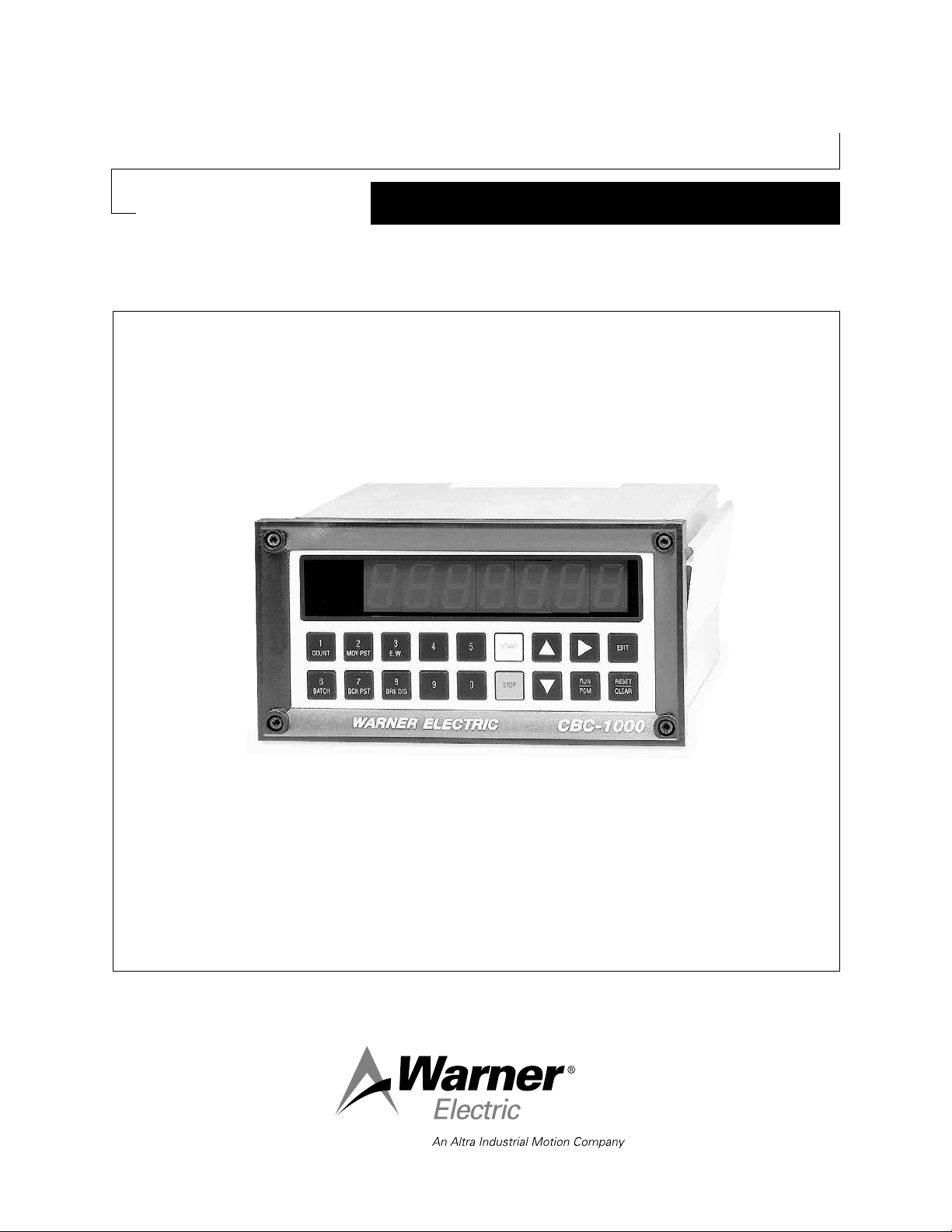
CBC-1000 Series Loop Unidirectional
Clutch/Brake Control System
P-275
819-0496
Installation & Operating Instructions
Page 2

Contents
Introduction
Ordering Information . . . . . . . . . . . . . . . . . . . . . . . . . . . . 2
Introduction . . . . . . . . . . . . . . . . . . . . . . . . . . . . . . . . . . 2
Selection Procedures . . . . . . . . . . . . . . . . . . . . . . . . . . . 3
Specifications . . . . . . . . . . . . . . . . . . . . . . . . . . . . . . . . . 4
Dimensions. . . . . . . . . . . . . . . . . . . . . . . . . . . . . . . . . . . 4
Control Overview . . . . . . . . . . . . . . . . . . . . . . . . . . . . . . 5
Operation . . . . . . . . . . . . . . . . . . . . . . . . . . . . . . . . . . . . 6
Diagnostics Tests . . . . . . . . . . . . . . . . . . . . . . . . . . . . . . 9
Programming . . . . . . . . . . . . . . . . . . . . . . . . . . . . . . . . 10
Installation . . . . . . . . . . . . . . . . . . . . . . . . . . . . . . . . . . 14
Applications . . . . . . . . . . . . . . . . . . . . . . . . . . . . . . . . . 18
Serial Interface . . . . . . . . . . . . . . . . . . . . . . . . . . . . . . . 20
Troubleshooting . . . . . . . . . . . . . . . . . . . . . . . . . . . . . . 25
Warranty . . . . . . . . . . . . . . . . . . . . . . . . . . . . . Back Page
Ordering Information
Model Number Part Number
CBC-1000 . . . . . . . . . . . . . . . . . . . . . . . . . 6060-448-001
Encoder Cable (Accessory) . . . . . . . . . . . . 6060-101-001
100 Pulse Per Revolution Encoder
w/10’ Cable. . . . . . . . . . . . . . . . . . . . . . . . 6060-101-010
250 Pulse Per Revolution Encoder
w/10’ Cable. . . . . . . . . . . . . . . . . . . . . . . . 6060-101-025
600 Pulse Per Revolution Encoder
w/10’ Cable. . . . . . . . . . . . . . . . . . . . . . . . 6060-101-060
1200 Pulse Per Revolution encoder
w/10’ Cable. . . . . . . . . . . . . . . . . . . . . . . . 6060-101-120
RS-232 to RS-422/485
Converter (Accessory. . . . . . . . . . . . . . . . . 6060-101-232
Warner Electric’s CBC-1000 is a closed-loop
positioning control with error compensation designed
for industrial clutch/brake applications. The position
loop is closed through encoder
feedback which generates pulses proportional to load
motion. The CBC-1000 uses this feedback to
determine the optimum brake actuation point. The
control can be programmed to operate in one of two
distinct modes: absolute or incremental. The CBC1000 includes eight solid state control outputs, a
batch counter and a serial communications interface.
The CBC-1000 system consists of four key
elements: the CBC-1000, a clutch/brake, a
clutch/brake control, and an encoder. Nearly any
electric clutch/brake size and configuration can be
used. These products are described in Warner
Electric’s Clutch/Brake Catalog, P-1234. The
Clutch/ Brake control, also found in Warner Electric’s
Clutch/Brake Catalog, should have solid-state
compatibility. Simple on-off, soft start/stop, and
overexcitation controls may all be utilized based on
the desired velocity profile. Warner Electric also offers
industrial grade encoders of various resolutions.
Failure to follow these instructions
may result in product damage, equipment damage,
and serious or fatal injury to personnel.
2
Warner Electric • 800-825-9050 P-275 • 819-0496
Page 3

Addendum Sheet
Warner Electric LLC
31 Industrial Park Road
New Hartford, CT 06057
tel 815-389-3771
fax: 815-389-2582
An Altra Industrial
Motion Company
CBC-1000AH
Service and Installation Instructions Additions to P-275
The CBC-1000AH Closed Loop Unidirectional Clutch/Brake Control System has had a feature addition and
the current manual number P-275 does not reflect this addition. The added feature is the auto home
capability (CBC-1000AH) which requires a marker input from the encoder to find its user defined home
position which might be lost during a power loss condition. There are a few simple steps that should be
followed to set up the CBC-1000AH properly.
1. Connect all the necessary components making sure the sig z wire (the marker pulse input) from the
encoder goes to control input 11 (sig z/marker) on the CBC-1000AH. This input was previously labeled
Continuous/Single.
2. After the encoder and the controls are installed and turned on, position the machine at home and reset
the counter.
3. Rotate the machine until the ‘ref’ light to the left/bottom of the display lights up.
4. Record the number displayed on the counter when the ‘ref’ light is lit.
5. Enter the programming mode by pressing the RUN/PGM key on the front panel of the control and
typing 1000. The number that you recorded should be put in programming line 1 (h, the home
reference number). Subsequently, all the programming line numbers in the P-275 manual will be
incremented by 1.
6. Every cycle when the CBC-1000AH sees the marker pulse the home reference number that was
recorded will be loaded into the counter value on the front panel display. It is important that this value is
as close as possible to what it should be. If more than ten cycles have occurred and your error is greater
than +/- 15, you should decrease/increase respectively the home reference number.
7. After cycling approximately ten times observe your actual braking distance number (BRK DIS, key 8 on
the front keypad) enter the programming mode and record this number in line 2 (bd, initial braking
distance). Subtract the home reference number recorded in line 1 from the move preset (MOV PST, key 2
on the front keypad). This number must be greater than the actual braking distance number. If the
braking distance number is larger, then the encoder needs to be rotated without the machine being
rotated to change where the marker pulse occurs. Otherwise, the marker pulse will occur after the brake
has come on and will not be detected.
8. Before exiting the program mode you will need to turn Count Retention off (CrEt, programming line 8). If
count retention is left on and a power failure occurs while the system is in its braking mode when power
is reapplied, it will take three cycles to find home.
The auto home feature will be very helpful when a power failure occurs and the encoder/control are unable to
track position. When power is reapplied a remote start can be applied and the machine will rotate until the
marker pulse is detected then the home reference number that was loaded in will be downloaded to the counter and CBC-1000AH will know its position and perform an accurate stop. The machine may miss its first home
position if the power up position is past where the marker pulse occurs.
The CBC-1000AH is programmed to not allow any outputs to fire until a home reference number is entered.
Also, depending on the speed of your system a lower resolution encoder may be needed to increase the length
of the marker pulse so it can be properly detected. The encoder that has been sent is a 600ppr
encoder. Therefore, your MOVE PRESET (key 2 on the front panel) needs to be changed to 600 if you are only
moving one revolution per cycle.
Page 4

Page 5

Selection Procedures
Select the Proper Clutch/Brake
Determine torque and inertia requirements.
Calculate heat dissipation for required cycle rate.
For best accuracy, mount clutch/brake directly on
nip or drive shaft. Avoid backlash.
Select Encoder (Quadrature)
Select encoder PPR for desired system resolution
(i.e., inches/pulse, degrees/pulse. Determine input
frequency; do not exceed 20 KHz (20,000 pulses/
sec). Mount encoder directly to nip or drive shaft for
best accuracy. Refer to Encoder Selection, page 7.
Select Clutch/Brake Power Supply
Use CBC-700 overexcitation control for best accuracy. Use CBC-500/550 for soft starting and/or
stopping. Note: Brake autogap may have to be
removed for best accuracy. Refer to clutch/brake
control, page 7.
Plan System Logic (Switching Requirements)
Use absolute mode for indexing applications such
as conveyors and turntables or cutoff applications
where close registration is required. Use
incremental mode for cutoff applications where
close registration is required. Use incremental mode
for cutoff applications. Refer to mode of operation,
page 8. Determine switching and relays required for
machine operation. Refer to pages 14-19 for
specific wiring options. Examples of incremental and
absolute wiring schematics are shown on pages 18
and 19.
Calculate Scaling Factor
Reference display scaling, page 8, to scale the
display to read inches, meters, degrees, rotations,
etc.
Determine Program Steps
Select absolute or incremental mode, output delays
and other options. Refer to Programming Section,
page 12.
Serial Communications
For data collection or remote operation, refer to
Serial Interface on pages 20-23.
Warner Electric • 800-825-9050 P-275 • 819-0496
3
Page 6
Specifications
RESET
CLEAR
Press
to clear error code
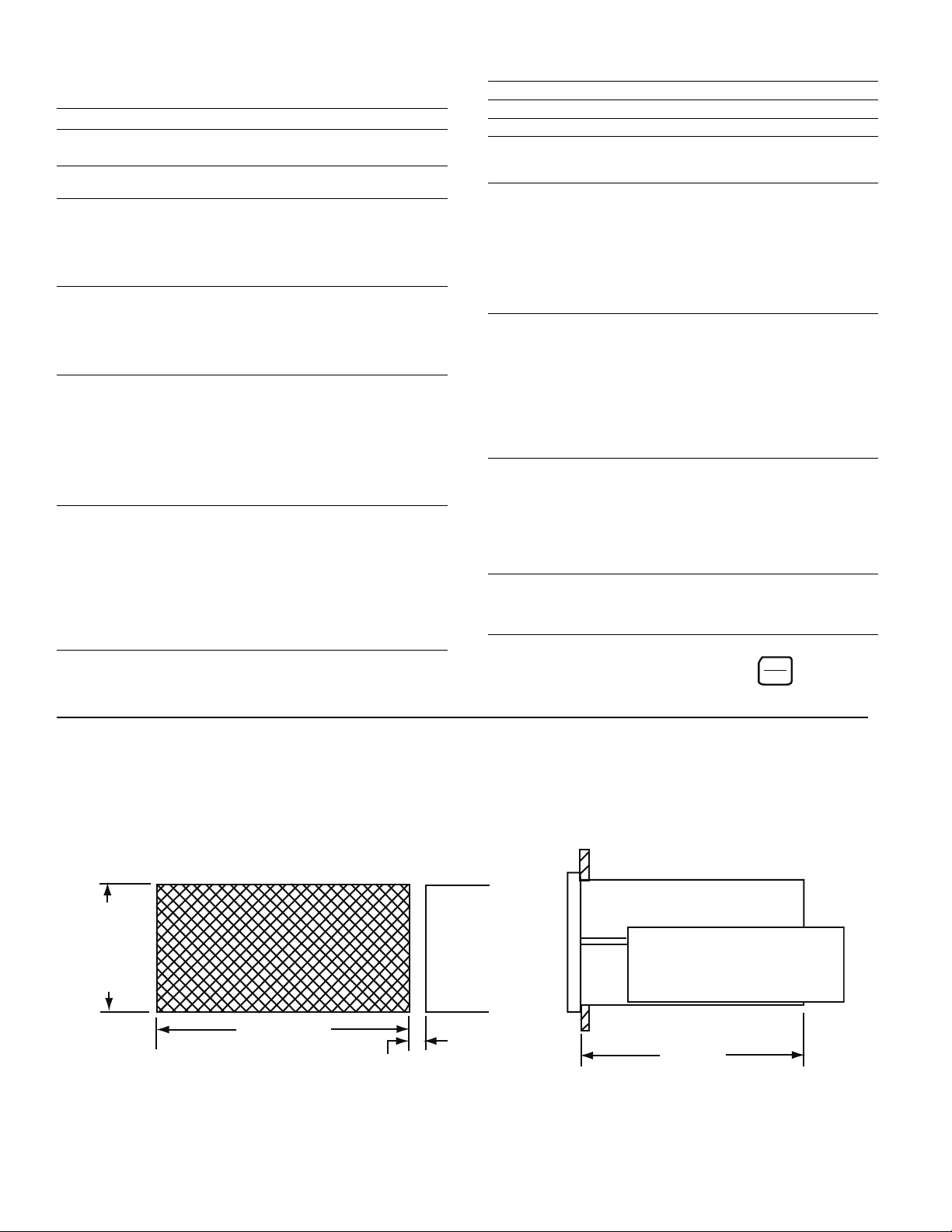
Make panel cutout. Affix adhesive gasket (if required) to panel. Remove
panel straps and slide unit thru cutout. Slide panel straps into enclosure
guides. Thread 5/8” long hex washer head screws into guides using a
3/16” hex driver and tighten securely.
5.43 ± 040
(138 + 1, -0 mm)
allow 0.32” (8mm) each
side between cutouts
2.68 ± .030
(68 + 1, -0 mm)
5.68
(144 mm)
Part No. 6060-448-001
Input Power 100 to 130 VAC, 50/60 Hz, 20VA
(200 to 260 VAC selectable)
Auxiliary Supply 12 VDC @ 175 mA
Used for powering encoder, etc.
Main Counter
Range 6 Decade
Reset Input 2 Individual with 6 decade range
Operation Quadrature
Reset Input External and front panel
Count Rate (20 kHz external input frequency)
Batch Counter
Range 6 Decade
Presets 1 with 6 Decade range
Operation Count UP by detecting Zero Speed
Reset Through front panel only
Output Latched, fixed to output terminal 21
Signal A and B Inputs
Input Frequency DC, 20 kHz quadrature max.
Input Type Single ended, Current Source
Input Logic Times 2
Input High Level 3.25 VDC min.
Input Low Level 1.75 VDC max.
Input Impedance 1.0Ω to common
Input current 3.25 mA steady state
Input Response 10 µs. min high and low time
Control Inputs
Input Frequency DC to 20 Hz max. each input
Input Type Single ended, current sinking
Input Logic Both Edge and Level sensitive
as defined by input use
Input High Level 10 VDC min. to 20 VDC max.
Input Low Level 0 VDC min. to 2 VDC max.
Input Impedance 4.7Ω pullup to +12 VDC
Input Current 2.5 mA steady state
Input Response 25 ms. make and break time
Display
Decade 7 Decade, 0.6" red LED
Decimal Point User programmable
Range: xxx.xxx to xxxxxx
Keyboard Sealed tactile feel, 18 positions
Program Security Program LOCK of lines 1 - 34
Control Outputs
Type 8 Solid State, 100 mA sink max.,
24 VDC max.
Serial Interface
Type RS-422A/485 compatible
Baud Rate Selectable: 300, 600, 1200, 2400
Parity Selectable: None, Odd, Even
Data ASCII
Format Start bit, 7 bit ASCII data, Parity bit,
Stop bit
I.D. Number Programmable 0 to 98: Allows
multidrop systems
Diagnostics
Test 0 Keyboard Test
Test 1 Non-Volatile RAM Test
Test 2 Input Test
Test 3 Output Test
Test 4 Display Test
Test 5 Program Memory Test
Test 6 Date Code Test
Test 7 Serial I/O Test
Test 8 Return to Factory Programming
Mechanical
Enclosure Aluminum extrusion with molded
VALOX bezel. 2.91” high x 5.67” wide x
6.03” deep overall
Weight 2.5 lbs.
Cutout 5.43” ± 0.04” x 2.68” ± 0.03”
Panel Thickness 1/16” to 1/4”
Panel Depth 5.68” minimum
Environmental
Operating Temp. 0° to +50°C (32° to 122°F)
Storage Temp. -18° to 85°C (0° to 186°F)
Ambient Humidity 90% and noncondensing
Controller Error Codes
Error 2: Low AC Line Voltage
Error 3: Input Frequency too fast
Error 4: Processor time fully utilized
Dimensions For Panel Mounting
4
Warner Electric • 800-825-9050 P-275 • 819-0496
Page 7
144.0001
CBC-1000WARNER ELECTRIC
E.W. PGM
CNT EDIT
BRK BCH
MOV PST
1
COUNT
2
MOV PST
3
E.W.
4
5
9
0
6
BATCH
7
BCH PST8BRK DIS
EDIT
RUN
PGM
RESET
CLEAR
START
STOP
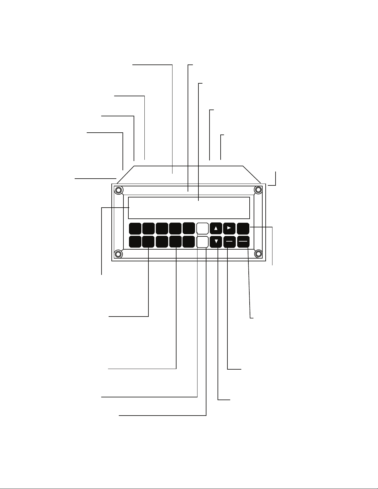
Metal Enclosure
• Improves Noise Immunity
• Eliminates RFI Emissions
• High Strength for Industrial Environment
Auxiliary Supply
Encoder Inputs
Control Inputs
Control Outputs
Display and Mode Annunciators
Display Function Keys
Numeric Keys 0-9
Start Key
Stop Key
CURSORS
RUN/PGM
RESET/CLEAR
EDIT
Neoprene Gasket Seal
AC Power Input
Serial Data I/O
Large LED Display
Sealed Front Panel
• NEMA 4 Rated
• 7 Decades
• High Intensity, High Contrast
• RS-422A/485
• Up to 32 units may be bussed together
• 115/230 VAC Selectable
• Built-in Line Filter
• Non-volatile Memory
• Used to enter the EDIT mode
to alter presets. Press again to
exit the EDIT mode
• Enabled by Programming Line
6 in the “off” position
• Resets the controller during operation
if Programming Line 5 is “on”
• Resets the Batch Counter if it
is being displayed
• Acts to clear the display in the
EDIT and PGM modes
• Used to switch between the RUN and
PGM modes
• UP: moves display toward top of program list in PGM mode
• RIGHT: moves display on same line in PGM mode
• DOWN: moves display thru programming steps in PGM
mode
• Used to initiate brake
• Used to initiate clutch
• Used to enter numeric
data in the EDIT and PGM modes
• COUNT: displays encoder input in engineering units
• MOV PST: displays desired length
• E.W.: displays desired duration of Early Warning
• BATCH: displays current batch count
• BCH PST: displays batch preset
• BRK DIS: displays stopping distance
• Displays the operation of the controller
(CNT, PGM, EDIT)
• Indicates what is being shown on the display
(MOV PST, E.W., BCH, BCH PST, BRK DIS)
• Start
• Early Warning
• Brake On (Stop)
• Zero Speed
• Zero Speed + Delay Time 1
• Zero Speed + Delay Time 2
• Auxiliary Start
• Batch Complete
• Start
• Stop
• Continuous/Single
• Reset
• Quadrature
• 12 VDC @ 175mA
Control Overview
Warner Electric • 800-825-9050 P-275 • 819-0496
5
Page 8
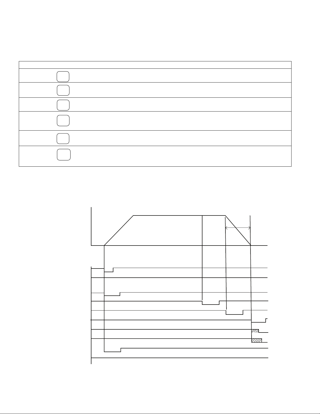
Operation
Velocity
(Speed)
Inputs:
(Active Low)
Outputs:
(Momentary)
(Edge Triggered)
Start
Start
Stop
Early Warning
Brake On
Zero Speed
Zero Speed & Delay Time 1
Zero Speed & Delay Time 2
Auxiliary Start
Batch Complete
1
0
1
0
1
0
1
0
1
0
1
0
1
0
1
0
1
0
1
0
Delay Time 1
Delay Time 2
Time
(count)
Braking
Distance
Brake On
Point
Early Warning
Point
Start
Point
Successful operation will require knowledge of the following definitions and their relationships to the
timing diagram.
Function Key Definitions
Count The actual move distance, in pulses or scaled into engineering units (inches, feet, rotations, degrees, etc.) displayed
Move Preset The desired move distance in pulses or scaled into engineering units. This is the value the operator enters to select a
Early Warning A distance prior to Move Preset at which the early warning output is activated. Expressed as pulses or engineering
1
COUNT
2
MOV
PST
3
E.W.
dynamically.
new move distance.It can also be locked during the RUN mode by simply programming line 6 to “off”.
units, this output can be used to accomplish a soft brake (slow down), energize valves, etc.
Batch A cumulative batch counter that can be dynamically displayed to show the number of operations, cycles, etc. When
6
BATCH
this counter reaches the value programmed by the Batch Preset (key 7) the Batch Complete Output (pin 21 on
CBC-1000) is activated. The batch counter can be manually or automatically reset.
Batch Preset A programmable batch counter activates the batch complete output when the value programmed has been reached
Braking Distance The actual distance required to stop. This value is dynamically updated to determine the brake actuation point.
7
BCH
PST
8
BRK DIS
by the batch (key 6).
Factory default is 25 pulses or engineering units which is only used for the first cycle after power-up. After the first
cycle the CBC-1000 will tune to the braking distance required.
Timing Diagram
6
Warner Electric • 800-825-9050 P-275 • 819-0496
Page 9

Operation
Speed Speed
Speed
On - Off
CBC-400
Time
Soft Start/Stop
Time
CBC-500
Note: Remove the brake autogap for
best
accuracy when soft stopping.
Overexcitation
Time
CBC-700
CBC-750
The CBC-1000 system cycle to cycle accuracy will
usually be plus or minus several encoder counts.
Various factors can affect positional
accuracy, the most significant of which are
discussed below:
d. System Resolution - Can also be increased
by mechanical means. For example,
decreasing the diameter of a nip roll
connected to the encoder will increase
system resolution.
The maximum encoder resolution at any operation
speed is:
Encoder Selection
a. Type - Only quadrature type encoders may be
used.
b. Location - The encoder should be mounted
as close as possible to the location where
accuracy is desired, minimizing the effects of
backlash and slippage. Direct mounting is
preferred to indirect mounting.
c. Resolution - Encoder resolution should be
maximized so the inherent plus or minus
several count tolerance equates to the
minimum linear or rotational inaccuracy. The
product of encoder counts and rotational
speed must be less than the input speed of
20,000 pulses per second (20kHz). The
adjacent table simplifies selection:
Clutch/Brake Control
1
x 20,000 x 60 = Max. PPR
RPM
Encoder Speed Encoder Resolution
(RPM) (pulses/rev.)
12,000 - 4,801 100
4,800 - 2,001 250
2,000 - 1,001 600
1,000 - 0 1200
480 - 0 2500
240 - 0 5000
Various velocity profiles may be achieved by properly selecting the clutch/brake control. These can
generally be classified as overexcitation, on-off, and soft start/stop as depicted by the profiles below.
These are shown in order of decreasing system accuracy. Accompanying each diagram are the
recommended clutch/brake controls per given classification. The control should have solid-state
switching. This will reduce unnecessary time delays inherent in electromechanical or mechanical
switching devices. In addition, the system will not require external components such as relays, etc.
Warner Electric • 800-825-9050 P-275 • 819-0496
7
Page 10

Mode Of Operation (Program Line 8)
The CBC-1000 is programmable to operate in either the absolute or incremental mode of operation.
Absolute mode is used in systems that tend to accumulate error. A common example is an indexing
conveyor or table. When used in this mode, the CBC-1000 maintains its position in an absolute sense and
compensates for any slight errors made on the prior move.
The incremental mode of operation is used for systems that will not accumulate error, such as a cut to length
paper sheeter or an auger filler. In such systems, each consecutive move is independent of the previous one.
In the incremental mode a reset signal to terminal 12 is required from one of the zero speed outputs or an
external source (Ref. page 18 for wiring diagram). The key to mode selection is programming line 8, Auto
Reset (on/off):
Absolute mode of operation - Auto Reset “On”
Incremental mode of operation - Auto Reset “Off”
Display Scaling (Program Line 3)
• Changing the CC & decimal point will affect presets
• CC should not exceed 1.0
• CC of .5 displays encoder pulses
The display can be easily scaled to display engineering units (inches, meters, degrees, rotations, etc). Line 3
of the programming (correction constant) prompts input of a factor (five decades) that will be multiplied by
the incoming pulse train to display the desired engineering units. Remember that the CBC-1000 includes a
times 2 internal multiplier effectively doubling the resolution of a given encoder. Thus, if one wishes to view
encoder pulses, a multiplier (correction constant) of ‘0.5’ should be entered on Line 3 in the programming
mode. The resolution of the encoder should be chosen to take advantage of the best instantaneous
accuracy of the calibrator. The best instantaneous accuracy is obtained with a correction constant setting not
exceeding 1.0000. The scaled units are also used to measure stop and move distances. Consequently, the
scaled units selected affect the system resolution. For example, with the correction constant set the display
at 1.0 inches, this is the smallest measurable increment. Remember, the decimal point must be programmed
(programming line 4) to display the desired display resolution. This resolution is also used in the denominator
of the correction constant equation. The general form of the equation for the correction constant is given
below.
CC (Correction Constant) = Distance traveled in engineering units per one revolution of the encoder
Display Resolution Desired X Encoder Resolution X 2
(0.001, 0.01, 1.0)
Example: Web measurement - Display in inches, display resolution in tenths of an inch
Encoder Resolution - 600 PPR
Mounting - Direct, via 4” diameter wheel
Calculation:
8
Warner Electric • 800-825-9050 P-275 • 819-0496
cc =
π0 = π x 4 = 12.5664
0.1 X 600 pulses/revolution X 2
= 0.1047
Page 11

t 0: Keyboard Test: Tests the function of the front panel keys.
Press to begin test. RUN: will be displayed. Press each front panel key except to
test key. The display will indicate if the key is functional.
t 1: Non-Volatile RAM Test: Tests CBC-1000 RAM.
Press to begin test. The test will return PASS or FAIL. Press to continue.
t 2: Input Test: Tests whether CBC-1000 is accepting inputs.
Press to begin test. Activate inputs to control.
If the input is received, a character will be displayed. “Ab” - Encoder
input, “1” - Start, “2” - Stop, “3” Continuous mode, “4” Reset. Press to continue.
t 3: Output Test: Used to determine whether CBC-1000 outputs are functional.
Press to begin test. Press keys 1-6 on the front panel. The corresponding output will
turn on and latch. Use a VOM to check for a high level state on terminal strip of CBC-1000.
Press to exit test.
t 4: Display Test: Tests function of each LED on front panel.
Press to begin test. Each digit of front panel display will automatically be turned on.
Check for faulty LEDs. Press to continue.
t 5: Program Memory Test: Tests program memory capability.
Press to begin test. PASS or FAIL will be returned. Press to continue.
t 6: Date Code Test: Displays software date code.
Press to display date code. Press to exit. Continue.
t 7: Serial Test: Tests connections with serial data interface module.
Press to begin test. PASS or FAIL will be displayed. Press to continue.
t 8: Factory Default Settings: Returns CBC-1000 to factory settings.
Press to return all program steps to factory default settings.
RUN
PGM
CBC-1000 Diagnostics Tests
Warner Electric • 800-825-9050 P-275 • 819-0496
9
Page 12

Programming
Press
Press
Press
Press
Press
Press
to display the current length or position (up to six digits).
to display the move preset (up to six digits).
to display the early warning preset (up to four digits).
to display the batch counter (up to six digits).
to display the batch counter preset (up to six digits).
to display the average braking distance (up to four digits).
1
COUNT
2
3
6
7
8
MOV PST
E.W.
BATCH
BCH PST
BRK DIS
Move
Preset
2
MOV PST
2
MOV PST
EDIT
EDIT
EDIT
EDIT
EDIT
EDIT
EDIT
EDIT
3
E.W.
7
BCH PST
1
6
COUNT
RESET
CLEAR
RESET
CLEAR
RESET
CLEAR
RESET
CLEAR
BATCH
RESET
CLEAR
Early
Warning
Batch
Preset
Batch
Counter
Reset
System
Home
To home the system: Press then press .
Press , then press , and press , now enter a new value using the numeric keys, then press .
Press
Press
Press
, then press
, then press
, then press
, and press
, and press
, and press
enter a new value using the numeric keys, then press .
enter a new value using the numeric keys, then press .
or to change the value incrementally. Then press .
, now
To manually reset the batch counter. , then press .Press
Or
View Presets and Values
The six function keys may all be viewed during the RUN mode. To view their values, press the desired function key and the value is displayed with the corresponding display annunciator. The controller process continues without interruption.
Entering Presets
The three presets (MOV PST, E.W., and BCH PST) may also be changed during the RUN mode provided that
programming line 6 (panel lock) is programmed “off”. To edit, press the desired preset function key, next
press the EDIT key followed by the CLEAR key. Enter the new value using the numeric keys, then press the
EDIT key to exit the edit mode and to replace the existing value in memory. The CBC-1000 will use the new
number entered after the edit mode is exited.
10
Warner Electric • 800-825-9050 P-275 • 819-0496
Page 13

Program Mode
Press
, then press
, then press
Move down one program line
or press
, then press line number, and press
Move up one program line
Select Options.
To exit the program: Press .
1
000
EDIT
RUN
PGM
RUN
PGM
COUNT
..
.
to jump to the line changing.
To enter the program mode to access the 34 features shown on pages 12 and 13, press the program key
and enter the 4-digit password (1000) followed by the down cursor. NOTE: Before entering the program
mode, the stop key or stop input should be activated. The CBC-1000 automatically activates the brake
upon entry into the program mode.
To enter the program mode:
Latching Outputs
To latch the outputs or keep the outputs activated until a certain position is reached during the cycle, all
zeros must be entered on programming lines 9-14 (shown on page 12). These latched outputs must be
turned off at a predetermined function (programming lines 19-22) by a drop command. Outputs may be
dropped at the Start command, Move Preset, Early Warning or Reset command. Press the front panel
buttons (1-6) and a “d” will be displayed for the output to be dropped.
Example: Program Line 19 ----.----.----.----. d
Releases zero speed + delay 2 output at start command
Latching the batch counter reset, which is programming line 15, requires the operator to manually reset
the batch counter (key 6) when it reaches the value programmed in the batch preset (key 7). By setting the
batch counter reset to momentary (00.01 to 99.99 seconds), the CBC-1000 will automatically reset the
batch counter and it will hold the batch complete output (pin 21) active for the time programmed.
Warner Electric • 800-825-9050 P-275 • 819-0496
11
Page 14

RESET
CLEAR
Programming
LINE DISPLAY DESCRIPTION OPTIONS DEFAULT
1 b d . Initial Braking Distance - - - - 2 5 The first brake distance used by the
CBC-1000 at power-up.
2 b d . Au E . # of Cycles Averaged 1 - 9 3 The number of cycles used for the running
average of brake distance.
3 c c . Correction Constant - . - - - - 0 . 5000 The scaling factor for the front panel display
(0.5000 for display in pulses).
4 d P . Decimal Point off, .0, .00, .000 oFF Number of decimal places displayed. Affects
all distance values in other registers.
5 F r S t. Front Panel Reset on - off on Enables or disables front reset in the RUN
Mode.
6 P L o c . Front Panel Lock on - off oFF “On” enables and “Off” disables changing
MOV PST, E.W., and BCH PST while running.
7 C r E t . Count Retention on - off on Retains system position during power off.
8 A r S t . AUTO Reset on - off oFF Select Absolute (ON) or Incremental (OFF)
mode of operation.
9 o 1 . Start Output 00.00 to 99.99 00 . 10 The duration (momentary or latched) of the
Start Output in seconds. For latched input,
enter all zeros or press .
10 o 2 . Early Warning Output 00.00 to 99.99 00 . 10 The duration (momentary or latched) of the
Early Warning output in seconds.
11 o 3 . Brake on Output 00.00 to 99.99 00 . 10 The duration (momentary or latched) of the
Brake On output in seconds.
12 o 4 . Zero Speed Output 00.00 to 99.99 00 . 10 The duration (momentary or latched) of the
Zero Speed output in seconds.
13 o 5 . Zero Speed + Delay 1 00.00 to 99.99 00 . 10 The duration (momentary or latched) of the
Zero Speed + Delay 1 output in seconds.
14 o 6 . Zero Speed + Delay 2 00.00 to 99.99 00 . 10 The duration (momentary or latched) of the
Zero Speed + Delay 2 output in seconds.
15 o 8 . Batch Counter Reset 00.00 to 99.99 LATCH Momentary for automatic (internal) reset or
latched for manual (operator) reset.
16 d 1 . Delay Time 1 00.00 to 99.99 0 . 50 The delay time for Zero Speed + Delay 1
output in seconds.
17 d 2 . Delay Time 2 00.00 to 99.99 1 . 00 The delay time for Zero Speed + Delay 2
output in seconds.
18 0 5 P . Zero Speed Window 01, .05,.10, .25 sec. 10 The time window in seconds to determine
Zero Speed, Zero Speed equals no pulses
received within window.
19 5 Start Command 1-6 - - - - - - Releases latched outputs at the start
Release Outputs command. Press 1-6 on the front panel to
release or drop output.
20 L Move Preset Release 1-6 - - - - - - Releases latched outputs at the move preset.
Outputs Press 1-6 on the front panel to release output
or drop output.
12
Warner Electric • 800-825-9050 P-275 • 819-0496
Page 15

Programming
LINE DISPLAY DESCRIPTION OPTIONS DEFAULT
21 E Early Warning 1-6 - - - - - - Releases latched outputs at the
Release Outputs Warning signal.
Press 1-6 on the front panel to
release output or drop output.
22 r Reset Command 1-6 - - - - - - Releases latched outputs at reset.
Release Outputs Press 1-6 on the front panel to
release output or drop output.
23 b r . Baud Rate off, 300, 600, 900 oFF See Serial Interface Section.
1200, 2400
24 P A r Parity nonE, odd, EuEn nonE See Serial Interface Section.
25 i d . n o . Identification Number 0 - 99 0 Control identification number. See
Serial Interface Section. See
Troubleshooting Section on page
25 for further information on
diagnostic tests listed below.
26 t 0 . Keyboard Test rdy y Front panel keyboard test.
27 t 1 . Non-Volatile RAM test Press y Non-Volatile RAM test.
28 t 2 Input Test Ab - encoder inputs Control input test.
1 - start
2 - stop
3 - cont. 4 reset
29 t 3 Output Test 1 - E y Control output test.
30 t 4 Display Test Press y Front panel display test.
31 t 5 Program Memory Test Press y Control program memory test.
32 t 6 Date Code Test Press y Displays Date Code of CBC-1000
33 t 7 Serial Test Press y Control serial test.
34 t 8 Factory Default Press y Returns control to factory default
Settings settings.
y
Refer to
Diagnostics
Test, Page 9
software.
Warner Electric • 800-825-9050 P-275 • 819-0496
13
Page 16

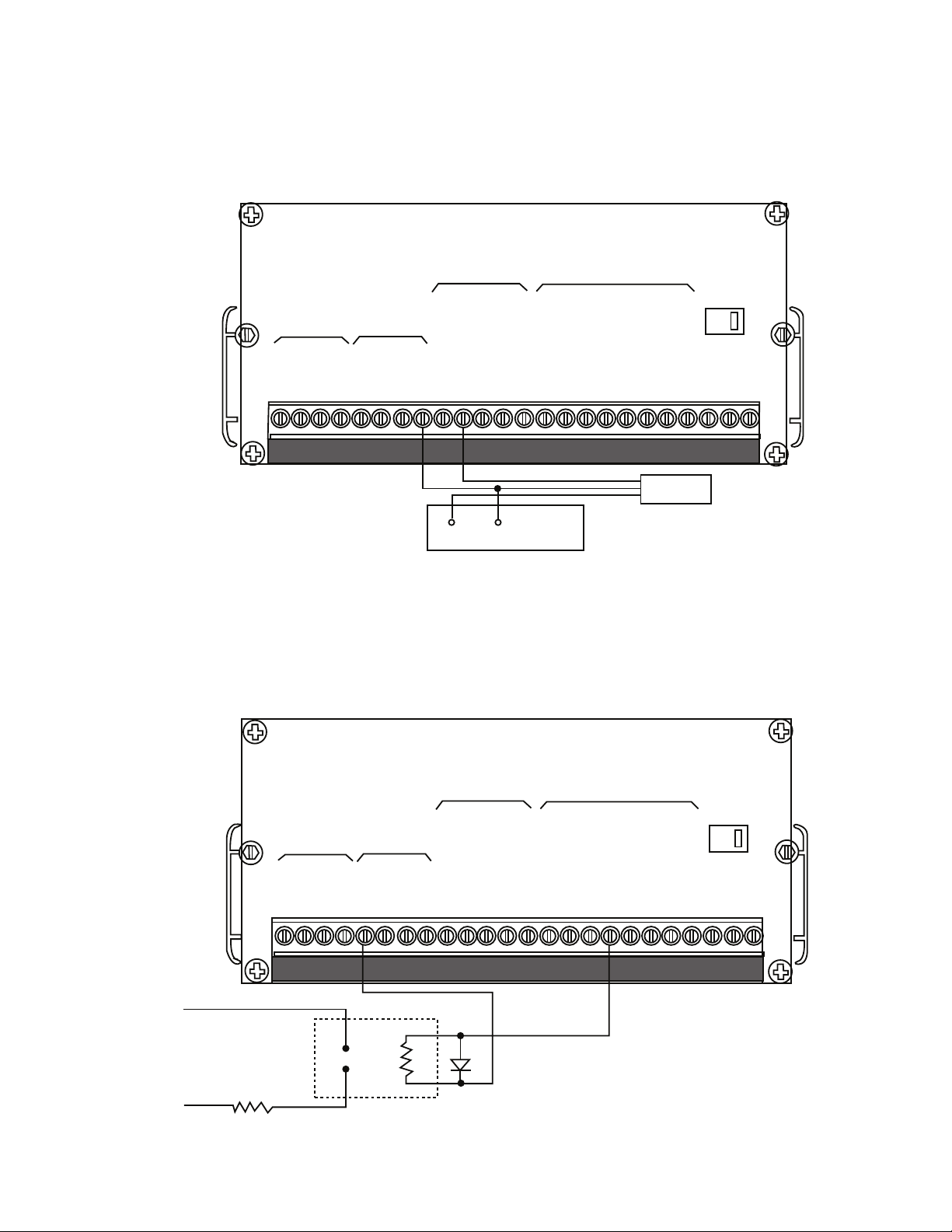
Installation
Note:
1) Set Selector switch for correct input voltage.
2) Unit is not fused. Wire through .25 AMP Slow
Blow fuse.
3) The case shield should not be used when the
encoder is mounted on a grounded surface.
Note: the Start Input is enabled by connecting
terminal 11 to terminal 13 (see below).
In the single cycle mode, the external start
input is ignored. The front panel start key must
be pressed to initiate the clutch.
In the continuous mode, both the front panel
start key and the external start input can be
used to initiate the clutch.
Closed: Continuous cycle mode
Open: Single cycle mode
Start
Reset
Serial
Date
Serial
Date
Serial
Date
Signal
Inputs
Signal
Inputs
Signal
Inputs
Control
Inputs
Control
Inputs
Control
Inputs
Control
Outputs
Control
Outputs
Control
Outputs
VAC
1 2 3 5 6 74 8 9 10 11 12 13 14 15 16 17 1819 20 21 22 23 24
1 2 3 5 6 74 8 9 10 11 12 13 14 15 16 17 1819 20 21 22 23 24
1 2 3 5 6 74 8 9 10 11 12 13 14 15 16 17 1819 20 21 22 23 24
VAC
VAC
+VDC
Sig A
Sig B
Common
(WHT)
(RED)
(BLUE)
(BLK)
Case
(Shield)
(BLK Heat Shrink)
Hot
Neut
115 VAC
0r
230 VAC
Bld. Gnd
Neutral
Hot
Batch Complete
Aux. Start
Zero Speed + Delay 2
Zero Speed + Delay 1
Zero Speed
Early Warning
Start
COM
Reset
Continuous/Single
Stop
Start
Brake On
COM
Sig B
Sig A
+12V
TXD +
TXD -
RXD +
RXD -
Bld. Gnd
Neutral
Hot
Batch Complete
Aux. Start
Zero Speed + Delay 2
Zero Speed + Delay 1
Zero Speed
Early Warning
Start
COM
Reset
Continuous/Single
Stop
Start
Brake On
COM
Sig B
Sig A
+12V
TXD +
TXD -
RXD +
RXD -
Bld. Gnd
Neutral
Hot
Batch Complete
Aux. Start
Zero Speed + Delay 2
Zero Speed + Delay 1
Zero Speed
Early Warning
Start
COM
Reset
Continuous/Single
Stop
Start
Brake On
COM
Sig B
Sig A
+12V
TXD +
TXD -
RXD +
RXD -
115
115115
Connection Diagrams
AC Input and Quadrature Encoder Input Wiring
Start and Reset Input Wiring
Continuous/Single Input Wiring
14
Warner Electric • 800-825-9050 P-275 • 819-0496
Page 17

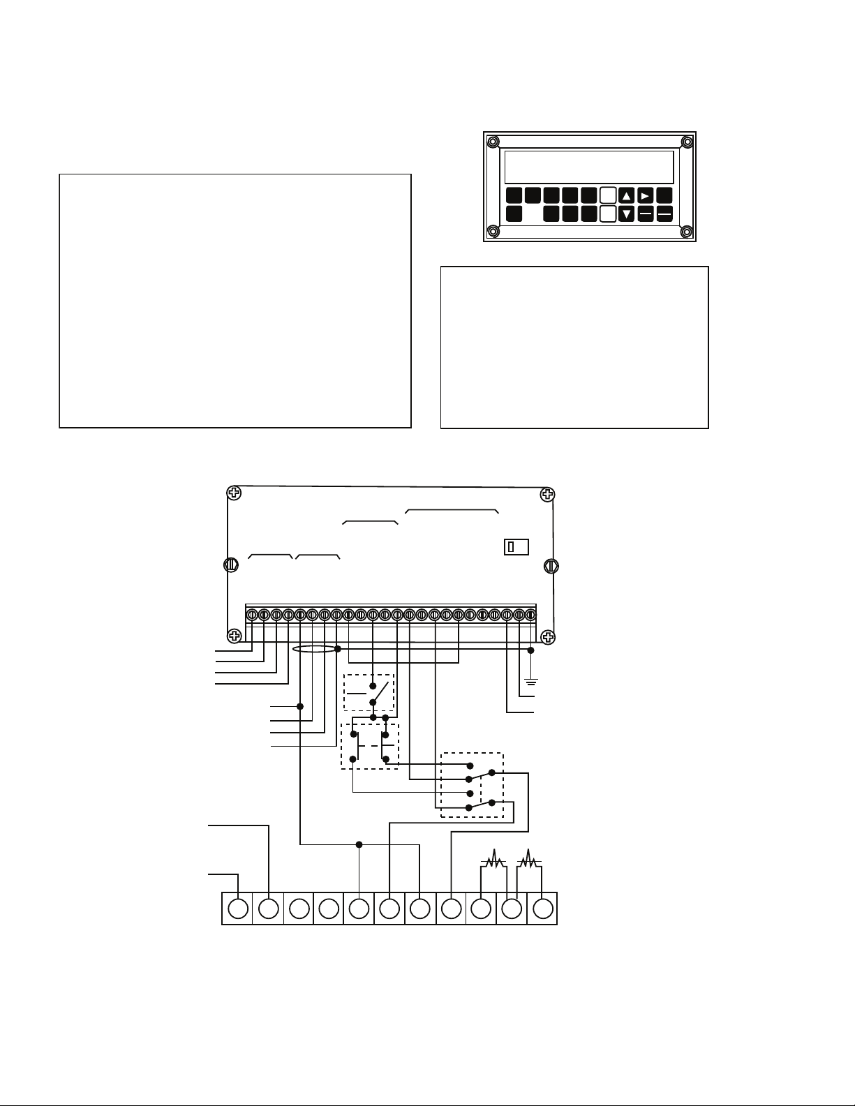
Installation
Serial
Data
Signal
Inputs
Control
Inputs
Control
Outputs
VAC
Serial
Data
Signal
Inputs
Control
Inputs
Control
Outputs
VAC
Closed: Brake On Output (terminal 16) activated
Open: Normal Operation
Note: A start input can not be executed when the switch is closed.
Stop
(E-Stop)
1 2 3 4 5 6 7 8 9 10 11 12 13 14 15 16 17 18 19 20 21 22 23 24
1 2 3 4 5 6 7 8 9 10 11 12 13 14 15 16 17 18 19 20 21 22 23 24
RXD -
RXD +
TXD -
TXD +
+ 12V
Sig A
Sig B
COM
Start
Stop
Continuous/Single
Reset
COM
Start
Early Warning
Brake On
Zero Speed
Zero Speed + Delay 1
Zero Speed + Delay 2
Aux. Start
Batch Complete
Hot
Neutral
Bld. Gnd
RXD -
RXD +
TXD -
TXD +
+ 12V
Sig A
Sig B
COM
Start
Stop
Continuous/Single
Reset
COM
Start
Early Warning
Brake On
Zero Speed
Zero Speed + Delay 1
Zero Speed + Delay 2
Aux. Start
Batch Complete
Hot
Neutral
Bld. Gnd
CBC-1000 Open Collector Outputs:
COM
(Terminal 13)
Output
(Terminals 14 thru 21)
100 mA. sink @ 24 VDC
115
Typical
of each
output
30V
- Connect to brake Input terminal of the clutch/brake control (i.e. Terminal 6 on the CBC-700)
- Connect to clutch Input terminal of the clutch/brake control (i.e. Terminal 8 on the CBC-700)
- Connect to clutch and brake Input terminals of the clutch/brake control (i.e. Terminals 5 & 7 on the CBC-700)
Connection Diagrams
Stop Wiring (E-Stop)
Control Output (Outputs 1-8, Terminals 14-21) Wiring
Duration of output signal controlled by programming lines 10-17.
Warner Electric • 800-825-9050 P-275 • 819-0496
15
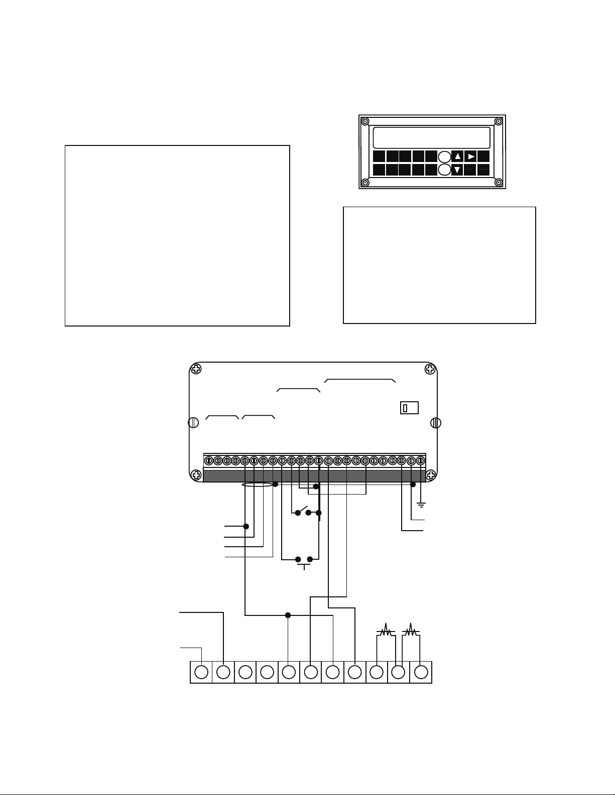
Page 18

Delay Timers 1 or 2 may be used to initiate an
external start input signal and function like a cycle
timer. The delay times are programmed on lines
16 and 17 of the program mode. In the diagram,
Delay Time 1 is used to initiate the external start
input signal to begin the next operation.
Note: the CBC-1000 must be configured in the
continuous mode as shown.
Output 4, 5 or 6 (Terminals 17, 18, 19) may be
used to reset the counter in the incremental
mode. Remember, in the incremental mode
(programming line 8, auto Reset -”off”) it is
necessary to externally reset the counter at the
completion of the previous operation. In the
diagram, Delay Time 1 (programming line 16) is
used to reset the counter, Delay Time 2 to start.
The Batch Complete Output may be used to stop
operations after a preset batch count (programmed
via function key 7, see page 10). Once this batch
preset has been reached, it is necessary to reset
the batch counter (function key 6, see page 10) to
continue another batch. The batch counter can be
reset manually or automatically by programming
line 15 (refer to page 12).
12345678910 11 12 13 14 1516 17 18 19 20 21 22 23 24
12345678910 11 12 13 14 1516 17 18 19 20 21 22 23 24
1 2345 678 910 11 12 13 14 15 16 1718 19 20 21 22 23 24
RXD -
RXD +
+12V
Sig A
Sig B
TXD -
TXD +
COM
Start
Stop
Continuous/Single
Reset
COM
Start
Early Warning
Brake On
Zero Speed
Zero Speed + Delay 1
Zero Speed + Delay 2
Aux. Start
Batch Complete
Hot
Neutral
Bld. GND
RXD -
RXD +
+12V
Sig A
Sig B
TXD -
TXD +
COM
Start
Stop
Continuous/Single
Reset
COM
Start
Early Warning
Brake On
Zero Speed
Zero Speed + Delay 1
Zero Speed + Delay 2
Aux. Start
Batch Complete
Hot
Neutral
Bld. GND
RXD -
RXD +
+12V
Sig A
Sig B
TXD -
TXD +
COM
Start
Stop
Continuous/Single
Reset
COM
Start
Early Warning
Brake On
Zero Speed
Zero Speed + Delay 1
Zero Speed + Delay 2
Aux. Start
Batch Complete
Hot
Neutral
Bld. GND
Serial
Data
Signal
Inputs
Serial
Data
Signal
Inputs
Serial
Data
Signal
Inputs
Control
Inputs
Control
Outputs
Control
Inputs
Control
Outputs
Control
Inputs
Control
Outputs
VAC
VAC
VAC
115
115
115
Installation
Connection Diagrams
Delay Timer Used as a Cycle Timer
Delay Timer Used to Reset the Count in the Incremental Mode of Operation
Batch Complete Configured to Stop Operation after Batch Preset has been Reached
16
Warner Electric • 800-825-9050 P-275 • 819-0496
Page 19
Installation
14
+12V
COM
Auxiliary
Power
Supply
Sensor
Note: Use shielded
wire on sensor
when far away
from control to
minimize noise.
-12V
+12V
Relay
115 VAC
Load
H
N
115 VAC
Serial
Data
Signal
Inputs
Control
Inputs
Control
Outputs
Power
Serial
Data
Signal
Inputs
Control
Inputs
Control
Outputs
Power
1 2 3 4 5 6 7 8 9 10 11 12 13 14 15 16 17 18 19 20 21 22 23 24
1 2 3 4 5 6 7 8 9 10 11 12 13 14 15 16 17 18 19 20 21 22 23 24
RXD -
RXD +
TXD -
TXD +
+12V
Sig A
Sig B
COM
Start
Early Warning
Continuous/Single
Reset
COM
Start
Brake On
Zero Speed
Zero Speed + Delay 1
Aux. Start
Batch Complete
Hot
Neutral
Bld. GND
Zero Speed + Delay 2
Early Warning
RXD -
RXD +
TXD -
TXD +
+12V
Sig A
Sig B
COM
Start
Early Warning
Continuous/Single
Reset
COM
Start
Brake On
Zero Speed
Zero Speed + Delay 1
Aux. Start
Batch Complete
Hot
Neutral
Bld. GND
Zero Speed + Delay 2
Early Warning
230
230
With Auxiliary Power Supply (Rear View)
Typical Sensor Wiring
Typical Relay Wiring
Warner Electric • 800-825-9050 P-275 • 819-0496
17
Page 20
Applications
E.W. PGM
CNT EDIT
BRK BCH
MOV PST
START
STOP
144.0001
CBC-1000WARNER ELECTRIC
1 2 3
4 5
678
9 0
EDIT
RUN
PGM
RESET
CLEAR
Programming Table
Line 8 Auto Reset ON
Line 16 Delay Time 1.200
NOTES:
1. Absolute mode requires Line 8 be “on” and that
reset be used only to “home”.
2. Continuous/Single switch used to stop machine at
end of cycle when in open position. Closed
position enables Start input, terminal 9
which will restart the machine.
Serial
Data
Signal
Inputs
Control
Inputs
Control
Outputs
VAC
From RS-422/485
Interface:
TXD —
TXD +
RXD —
RXD +
+ VDC
SIG A
SIG B
COMMON
CBC-700-90: 120 VAC
CBC-700-24: 24 VAC
Brake Input Clutch Input
+ +
—
—
Aux.
Supply
(12 VDC)
+
—
Brake Clutch
CBC-700:
(WHT)
(RED)
(BLUE)
(BLK)
Cont.
Single
CL
JOG
RUN
JOG
RUN
JOG
RUN
12345678910 11
Note:
Counter must be reset after
Jogging to a new home position.
Note:
Case shield should not be
used when the encoder is
mounted on a grounded
surface.
HOT
NEUT
115 VAC
CASE
(Shield)
RXD —
RXD +
TXD —
TXD +
+ 12V
Sig A
Sig B
COM
Start
Stop
Continuous/Single
Reset
COM
Start
Early Warning
Brake On
Zero Speed
Zero Speed + Delay 1
Zero Speed + Delay 2
Aux. Start
Batch Complete
Hot
Neutral
Bld. GND
115
12345678910 11 12 13 14 15 16 17 18 19 2120 22 23 24
COUNT
MOV PST
E.W.
BATCH
BCH PST
BRK DIS
Absolute Mode of Operation
18
Warner Electric • 800-825-9050 P-275 • 819-0496
Page 21
Applications
NOTES:
1. Incremental mode requires Reset before restarting.
This may be achieved using outputs 5 or 6.
CAUTION: Machine may restart following key pad
STOP. Continuous/Single Jumper enables esternal start input generated through Output 6, terminal 19. Keep single continuous switch open to
disable the external start signal.
Programming Table
Line 8 Auto Reset OFF
Line 16 Delay Time 1.70
Line 17 Delay Time 21.0
144.0001
CBC-1000
WARNER ELECTRIC
E.W POM
CNT EDIT
BRK BCH
MOV PST
1 2
3
4
5
6 78
9
0
COUNT MOV PST
E.W.
BATCH
BCH PST BRKDIS
STOP
START
EDIT
RESET
CLEAR
RUN
PGM
+VDC
SIG A
SIG B
COMMON
(WHT)
(RED)
(BLUE)
(BLK)
STOP
START
CBC-700:
Aux.
Supply
(12 VDC)
+
Brake Input
Clutch Input
+
+
_
_
_
Brake
Clutch
(Shield)
NEUT
HOT
115 VAC
Note:
Case shield should not be
used when the encoder is
mounted on a grounded
surface.
VAC
Control
Outputs
Control
Inputs
Signal
Inputs
Serial
Data
1 2 3 4 5 6 7 8 9 10 11 12 13 14 15 16 17 18 19 20 21 22 23 24
RXD –
RXD +
TXD –
TXD +
+12V
Sig A
Sig B
COM
Start
Stop
Continuous/Single
Reset
COM
Start
Early Warning
Brake On
Zero speed + Delay 1
Zero speed + Delay 2
Aux. Start
Batch Complete
Hot
Neutral
Bld. GND
Zero Speed
115
CBC-700-90: 120 VAC
CBC-700-24: 24 VAC
1 2 3 4 5 6 7 8 9 10 11
Incremental Mode Of Operation
Warner Electric • 800-825-9050 P-275 • 819-0496
19
Page 22
Serial Interface
RS-232 to
RS-422/485
converter
RS-232 to
RS-422/485
converter
RXD
RXD
RXD
RXD
COM
COM
COM
COM
TXD
TXD
TXD
TXD
—
—
—
—
+
+
+
+
RXD —
RXD +
TXD —
TXD +
COM
1234 8
CBC-1000
CBC-1000
CBC-1000
RXD —
RXD +
TXD —
TXD +
COM
BLDG
GND
RXD —
RXD +
TXD —
TXD +
COM
BLDG
GND
Bldg Gnd
Bldg Gnd
COMPUTER
TXD +
from
CBC-1000
TXD —
COM
To
Receiver
+5V
(2)
10 kΩ max. to
100 Ω min.
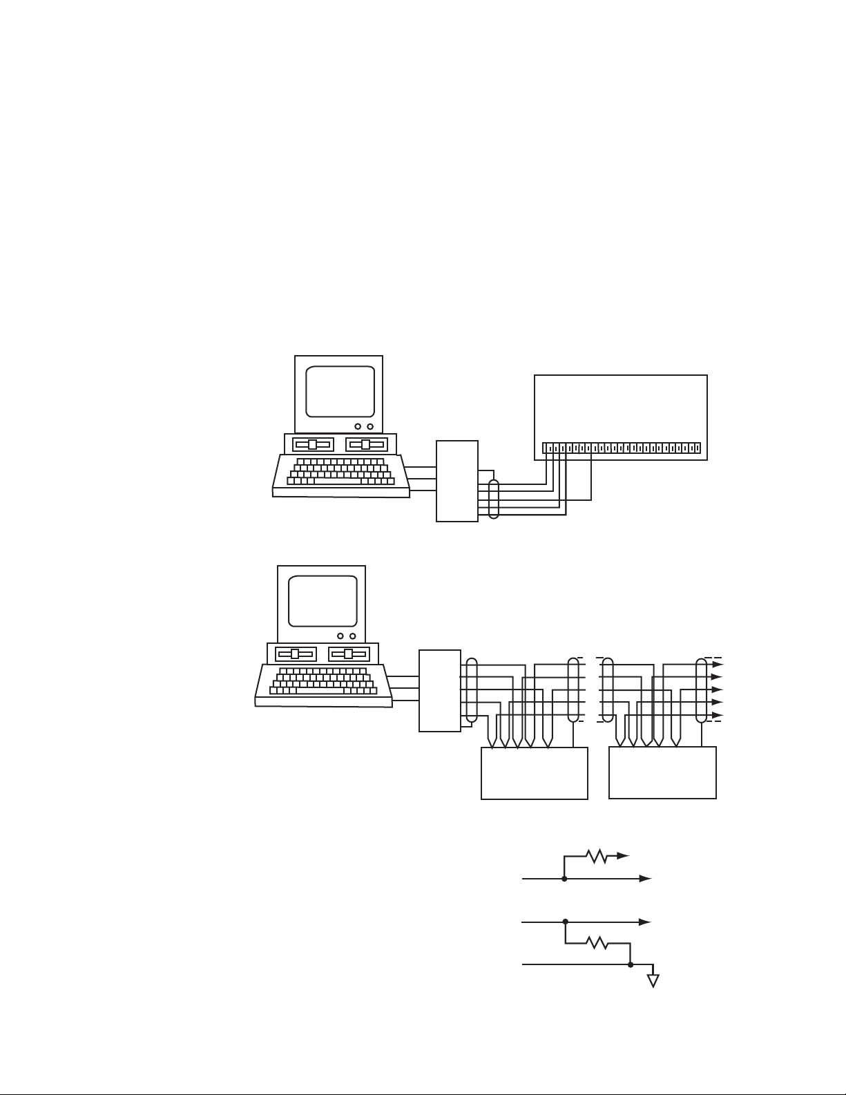
Overview
The CBC-1000 is equipped with an RS-422A/485 Serial Interface for remote data collection,
programming and networking applications. Front panel keyboard and some external control inputs
are supported. Additionally, facilities are provided for individual (local) and group (global) control of
single and multiple unit configurations respectively in a bus oriented system. Knowledge of serial
communications and the ASCII data format is required by the user who wishes to use the remote
capabilities or to integrate the control into a larger system.
Two applications will be discussed. The first consists of a single CBC-1000 and a display terminal. It
explains the use of the serial commands that mimic the keyboard operation and some control
inputs. An application of multiple units under the control of a host computer will also be discussed.
Single Unit Wiring
20
Multiple Unit Wiring
Termination
The RS-422A/485 receivers require termination to
minimize the effects of noise while the bus is not
being driven. The CBC-1000 incorporates the
terminations internally (as shown). When
connection is made to an RS-422/485 device other
than the CBC-1000, the receiver should be
terminated as shown.
Warner Electric • 800-825-9050 P-275 • 819-0496
Page 23

Serial Interface
Cable Selection
The CBC-1000 serial interface uses a simple
interconnect scheme and low cost wiring making it
superior to parallel data transfer schemes. Through
three wire pairs, remote operation at distances up to
5,000 feet can be implemented. The following
general guidelines should be observed:
1. Use #24 AWG Twisted pair, overall
shielded cable.
2. Use a “daisy chained” connection scheme for bus
systems.
In the RUN mode the numbers 1, 2, 3, 6, 7, & 8
cause new lines to be transmitted.
We have seen how the CBC-1000 control works for
remote viewing; we will now see how
programming may be done from a remote
location.
You may program only one CBC-1000 control at a
time. If the unit is in program mode via the front
panel keyboard, then it will not respond to the serial
input. To enter the PROGRAM mode, first send the
RUN/PGM (‘P’) character. The control will “answer”
by transmitting the LOC entry line as shown below.
3. if a “multidrop” system is used, keep the drop
length at 10% of the main line.
4. Tie the cable shield to Building Ground at the
CBC-1000 end of the cable.
Single Unit Operation
The operator can monitor the control locally via the
front panel keyboard and display. The serial
interface extends these monitoring activities to a
remote location. The connection of a remote display
terminal is straightforward. The baud rate and parity
for both devices must be the same. The ID number
should be set to ‘0’ (line 25 in the program table).
When power is applied to the CBC-1000 control, it
will start a continuous serial transmission of the
count:
CBC-1000 Display R: CNT. 123.456
when in the RUN mode.
The function keys (1, 2, 3, 6, 7, & 8) are set to scroll
down through the eight RUN modes lines.
For example:
Host Mode CBC-100 Display
1 R: CNT 123.456
2 R: MOV PST 11.50
3 R: E.W. 0.25
6 R: BCH 1500
7 R: BCH PST 2500
8 R: BRK DIS 0.25
Host Mode CBC-1000 Display
P R: LOC. 1
The control remains active (in the RUN mode) until
the proper lock combination is entered. Each
numeric entry is entered from right to left “calculator
style”. The character sequence 1-0-0-0 would
produce the following display on the terminal:
Host Mode CBC-1000 Display
1 R: LOC. 1
0 R: LOC. 10
0 R: LOC. 100
0 R: LOC. 1000
When this combination is correctly entered with a
down cursor from the CBC-1000 keyboard or “D”
from Host Terminal, the control exits the RUN mode
and enters the PROGRAM mode and returns with
the following:
Host Mode CBC-1000 Display
D P: bd. 25
Note that the PROGRAM (‘P’) prompt is now
shown. You are at the top of the PROGRAM table
(line 1) as shown on page 12. Once the PROGRAM
mode has been entered it is possible to program
any line in the table. Refer to the COMMAND
CHARACTER table for the keyboard equivalent
serial characters. A programming example is shown
on page 23.
Warner Electric • 800-825-9050 P-275 • 819-0496
21
Page 24

Serial Interface
Host Mode CBC-1000 Display
C P: MOV PST .000
4 P: MOV PST .004
5 P: MOV PST .045
6 P: MOV PST .456
7 P: MOV PST 4.567
8 P: MOV PST 45.678
9 P: MOV PST 456.789
The first serial entry (‘C’) clears the data field for the
current line. As can be seen in the COMMAND
CHARACTER table, this character mimics the
RESET/CLEAR key. Numeric data entry is self
explanatory.
Multiple Unit Operation
For multiple unit systems (up to 32 units) a special
addressing scheme is implemented so no conflicts
arise on the serial bus. Each unit is given a unique
serial address (ID number entered on line 25). Such
a system application is shown on page 20. All units
are programmed with the same baud rate and
parity. It is advised that the initial ID number
programming be done before the units are
bussed together.
To control one CBC-1000 in a bus oriented system
the host must first address it by sending an
ADDRESS COMMAND SEQUENCE. This is shown
below.
host: (ESC) A nn (where nn is unit number 1 to 99)
This escape code sequence will suspend the
transmission from all units including the one that is
addressed. The addressed unit will respond to all
subsequent commands while the other units just
“listen” on their receive input and turn their transmit
output off.
In some cases the host may want to send many
commands to a CBC-1000 control without waiting
for responses. This may be done by first
suspending transmission (CTRL S) then by
requesting a single UPDATE.
host: (ESC) U
Setup Mode Operation
The SETUP mode may be entered directly from the
RUN mode by cursoring to the desired SETUP line
(4-8) using the ‘D’ command character then sending
the ‘L’ command character which mimics the KEY
keyboard key. This action will place the control in
the SETUP mode allowing the user to change the
data in lines 3 through 8 in the program table. Serial
entry into the SETUP mode has the same
operational requirements and restrictions as if it
were entered via the front panel keyboard. Refer to
pages 6-8 for a complete operational description.
Preset setpoints are changed using the numeric
RST/CLR and DOWN cursor keys. The SETUP
mode is exited by sending another ‘L’ command
character at which time the controls revert back to
the RUN mode.
Remote Operation
Some of the unit’s CONTROL inputs are
effectively duplicated by serial commands, so it is
possible to implement a single or multiple unit
system with remote capability. Such a system can
be used for multiple machine, multiple axis or
multiple section applications. Keep in mind the
addressing requirements for multiple unit systems
previously discussed.
To receive data from an addressed unit the host
sends it a command to resume transmission using
the RESUME control character, (CTRL Q).
If you wish to suspend data data transmission you
may do so by using the SUSPEND control
character, (CTRL S).
22
Warner Electric • 800-825-9050 P-275 • 819-0496
Page 25

Serial Interface
HIGH
LOW
S D0 D1 D2 D3 D4 D5 D6 P S
ʻ
(sp)(sp) (sp) (cr)(cr) R : Co . 12 3 . 45 6
Two types of commands are available, LOCAL and
GLOBAL. LOCAL commands affect only the unit
that is currently addressed. GLOBAL commands on
the other hand affect all units regardless of address.
In this way it is possible to command many units to
begin control at the same point in time. The table
below lists the LOCAL and GLOBAL commands
that are supported.
LOCAL and GLOBAL COMMANDS
Control
Command
Output
Control Control Input
Batch
Reset to Zero
Counter
Reset to Zero
LOCAL GLOBAL Comments
(ESC) LO (ESC) GO
(ESC) LB (ESC) GB
(ESC) LR (ESC) GR
Simulates Output
Resets Batch
Reset Counter
Formats and Protocol
Character Format
The serial interface sends and receives information
by characters consisting of 10 bits. The
RS-422A/485 interface requires a 0.2V minimum
differential across + and - terminals. A logic high
(mark) is a positive differential and a logic low
(space) is a negative differential. ( Connection to
EIA-422/485 equipment that uses the opposite
polarity requires swapping the + and - connections
at the other equipment.)
Parity Bit (see note)
The parity bit is programmable as “Odd”, “Even”, or
“No” parity. Odd and Even parity force the total
number of data bits to be even or odd for data that
is transmitted by the CBC-1000 control. Incoming
parity is always compared to the calculated parity.
Characters with parity errors are discarded. If No
parity is selected incoming parity is ignored.
Characters are transmitted with Odd or Even parity
as selected on line 24 of the program table. If No
parity is selected then “high” bit is added as an
extra Stop bit.
Baud Rate (see note)
Select the baud rate to match the device
communicating with the control. You may select:
300, 600, 1200, or 2400 baud on line 23 of the
program table. Gaud rate is common to both
transmitter and receiver.
Line Format
The CBC-1000 control transmits only complete
lines. The driver is turned off when not transmitting
causing the bus to enter a “float” state. Ignore data
on the bus during this “float” time. Unless otherwise
commanded, the CBC-1000 control continuously
transmits the Count Value. The line format is as
follows:
• a carriage return at the beginning of a line
• a prefix indicating RUN, SETUP, or
PROGRAM
• a unique line mnemonic
• a five digit data field with decimal point
• a carriage return at the end of the line
The character format is as follows:
• Start bit (“low”) logic level)
• ASCII data (7 bits), least to most significant
• Parity bit (programmable)
• Stop bit (“high” logic level”)
Note: To make changes in Parity or Baud Rate
power must first be removed then reapplied after
program changes to either are made. Both Parity
and Baud Rate are initialized when the control
“powers up”.
Warner Electric • 800-825-9050 P-275 • 819-0496
23
Page 26

Command Characters
ʻSʼ
“U”
ʻCʼ
“Q”
ʻDʼ
thru
ʻEʼ
ʻRʼ
ʻPʼ
ʻ0ʼ THRU ʻ9ʼ
RUN
PGM
EDITSTOP
0
STAR T
RESET
CLEAR
(
Command Characters mimic the operation of the front
panel keyboard. Below is a list of the serial equivalents of
the front panel keys.
Control Characters
Two control characters are used to start and stop
the transmission from the CBC-1000 control. They
are shown below:
(CTRL) S Suspends transmission following the
completion of a line being sent. The
driver will then be turned Off.
(CTRL) Q Resumes transmission from a unit that
had been turned Off. The RUN mode line
currently selected will be
continuously updated.
Protocol
The CBC-1000 will “buffer” up to 16 Command and
Control Characters (but not Escape Code
Sequences) listed above, sent in “burst mode”.
Those characters are read, in order, every 20 msec.
The protocol should be careful not to overflow the
receive buffer. Additionally, Escape Code Sequences
should not be sent until the buffer has emptied and
all characters have been processed.
Escape Code Sequences
Escape code sequences are a group of special
commands used for bus oriented systems. Every
CBC-1000 control recognizes these commands.
The two listed below are in addition to those listed
in the table of LOCAL and GLOBAL commands.
(ESC) A nn The Address command is used to
select a single control within a
system. Only that unit whose serial
I.D. number matches the two digit
serial address (nn) will be selected.
Only that unit will respond to
subsequent serial commands. All
units, even the addressed one,
suspend transmission.
(ESC) U The Update command instructs the
currently addressed unit to transmit a
single line only.
24
Warner Electric • 800-825-9050 P-275 • 819-0496
Page 27

RESET
CLEAR
RESET
CLEAR
RESET
CLEAR
RESET
CLEAR
Troubleshooting
Problem Solution
Machine starts but does not stop
Establish a move Preset
Ensure brake functions properly using output test.
Display counts backwards Reverse encoder A, B, wiring.
Control may be responding to a start command. Check for
Machine stops but then restarts
transient signals. Use a Single/Continous switch which
disables the external start command.
System works well except for first cycle after power
down
Control appears to function perfectly but the but the
actual error is greater than the display indicates.
System accumulates error.
Control accumulates too many counts. Home zero position is drifting.
Monitor “Braking Distance” during successful operation, then
program this value into “Initial Braking Distance” Line 1.
Check for slippage between the encoder and the manual
items.
Change to Absolute Mode by programming Auto Reset (line
8) “on”. DO NOT use external reset except to home.
Check Display Scaling, page 8, and check for electrical
noise, such as ground loops. Eliminate noise.
Control appears to work but proper motion is not occuring.
System does not operate and fails diagnostic tests 1, 4,
5, or 7. Reference page 9.
System stops, but does not fire outputs.
Review Clutch Brake and Control Service Manuals. Use
Output Test (line 29) to verify performance.
Return unit for repair, call an Authorized Warner Electric
Distributor.
Lower zero speed window (line 18) to minimize effects of
encoder ”bounce” caused by vibrations.
Error Codes
If an error message appears
Error Code 2 - Low Line Voltage. Correct line voltage. Press to clear error code.
Error Code 3 - Feedback too fast.
Disconnect power to CBC-1000 momentarily and error
should clear. Press to clear error code.
Reduce encoder resolution and/or speed to keep encoder
feedback less than 20,000 PPS. Press
to clear error code.
Error Code 4 - Process Time fully utilized
Warner Electric • 800-825-9050 P-275 • 819-0496
Reduce encoder resolution or consult factory.
Press to clear error code.
25
Page 28

Warranty
Warner Electric LLC warrants that it will repair or replace (whichever it deems advisable) any
product manufactured and sold by it which proves to be defective in material or workmanship
within a period of one (1) year from the date of original purchase for consumer, commercial or
industrial use.
This warranty extends only to the original purchaser and is not transferable or assignable without
Warner Electric LLC’s prior consent.
Warranty service can be obtained in the U.S.A. by returning any defective product, transportation
charges prepaid, to the appropriate Warner Electric LLC factory. Additional warranty information
may be obtained by writing the Customer Satisfaction Department, Warner Electric LLC, 449
Gardner Street, South Beloit, Illinois 61080, or by calling 815-389-3771.
A purchase receipt or other proof of original purchase will be required before warranty service is
rendered. If found defective under the terms of this warranty, repair or replacement will be made,
without charge, together with a refund for transportation costs. If found not to be defective, you
will be notified and, with your consent, the item will be repaired or replaced and returned to you
at your expense.
This warranty covers normal use and does not cover damage or defect which results from
alteration, accident, neglect, or improper installation, operation, or maintenance.
Some states do not allow limitation on how long an implied warranty lasts, so the above limitation
may not apply to you.
Warner Electric LLC’s obligation under this warranty is limited to the repair or replacement of the
defective product and in no event shall Warner Electric LLC be liable for consequential, indirect,
or incidental damages of any kind incurred by reason of the manufacture, sale or use of any
defective product. Warner Electric LLC neither assumes nor authorizes any other person
to give any other warranty or to assume any other obligation or liability on its behalf.
WITH RESPECT TO CONSUMER USE OF THE PRODUCT, ANY IMPLIED WARRANTIES WHICH
THE CONSUMER MAY HAVE ARE LIMITED IN DURATION TO ONE YEAR FROM THE DATE OF
ORIGINAL CONSUMER PURCHASE. WITH RESPECT TO COMMERCIAL AND INDUSTRIAL
USES OF THE PRODUCT, THE FOREGOING WARRANTY IS IN LIEU OF AND EXCLUDES ALL
OTHER WARRANTIES, WHETHER EXPRESSED OR IMPLIED BY OPERATION OF LAW OR
OTHERWISE, INCLUDING, BUT NOT LIMITED TO, ANY IMPLIED WARRANTIES OF
MERCHANTABILITY OR FITNESS.
Some states do not allow the exclusion or limitation of incidental or consequential damages, so
the above limitation or exclusion may not apply to you. This warranty gives you specific legal rights
and you may also have other rights which vary from state to state.
Changes in Dimensions and Specifications
All dimensions and specifications shown in Warner Electric catalogs are subject to change without
notice. Weights do not include weight of boxing for shipment. Certified prints will be furnished
without charge on request to Warner Electric.
Warner Electric LLC
431 Industrial Park Road
815-389-3771
www.warnerelectric.com
An Altra Industrial Motion Company
P-275 819-0496 06/11 Printed in USA
• Fax: 815-389-2582
• New Hartford, CT 06057
 Loading...