

Page 1
B30 Single Range Tensioncells
P-2012-4
819-0404
Installation Instructions
Page 2

Contents
General Information . . . . . . . . . . . . . . . . . . . 3
Installation and Operation . . . . . . . . . . . . . . . 7
Adjustments . . . . . . . . . . . . . . . . . . . . . . . . . 8
Troubleshooting . . . . . . . . . . . . . . . . . . . . . . 9
Recalibration . . . . . . . . . . . . . . . . . . . . . . . 10
Dimension Drawing . . . . . . . . . . . . . . . . . . 12
Warranty . . . . . . . . . . . . . . . . . . . . . . Back Page
Failure to follow these
instructions may result in product damage,
equipment damage, and serious or fatal
injury to personnel.
Warner Electric • 800-825-9050 P-2012-4 • 819-0404
2
Page 3
Description
W1
W2
Machine
Frame
B30 Series Tonsioncell
Single Bolt Mounting
Internal
Bearing
Damper
C-Flexure
Far Side
Mechanical Stop
Load
Plate
LVD T
LVDT
Core
General Information
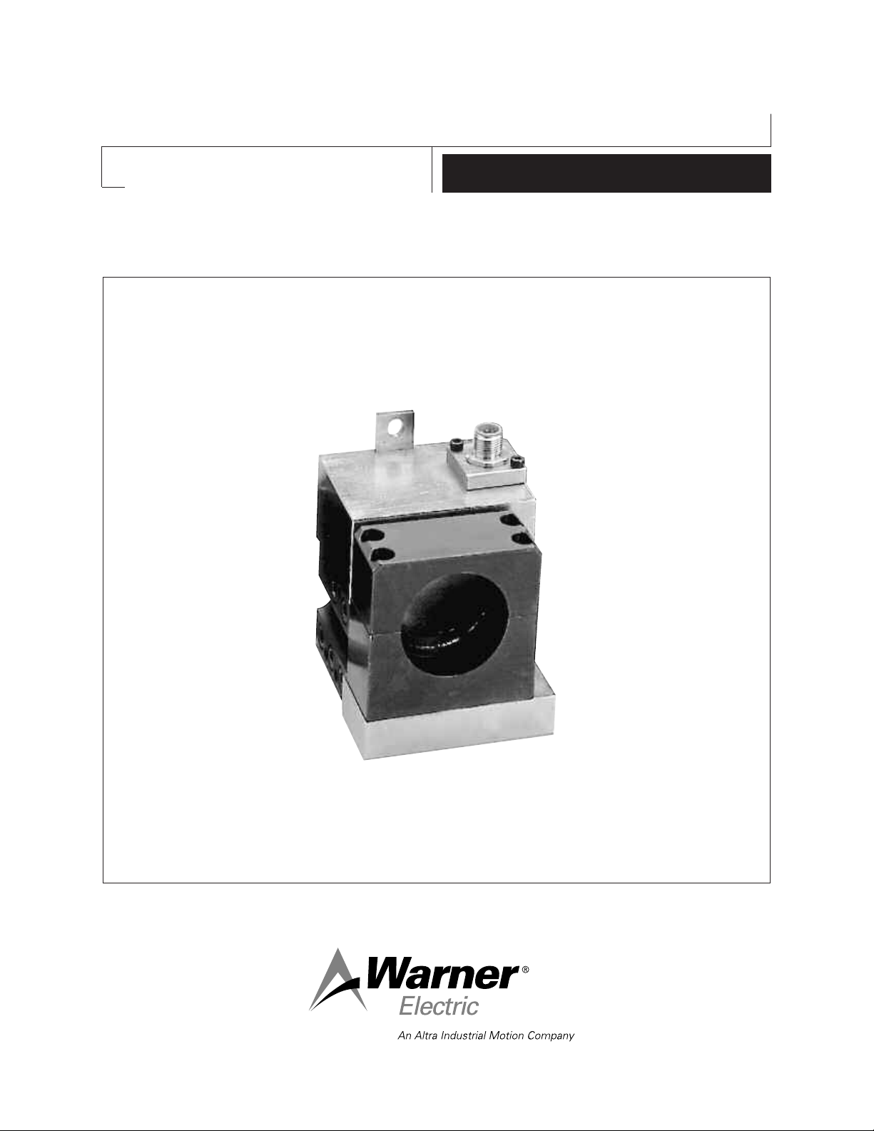
Warner Electric Series 30 Type B Tensioncells
are force transducers especially designed to
measure and control web tension on continuous
strip processing lines. They are normally installed in matched pairs at each end of a measuring roll. (See Figure 1)
A Tensioncell consists of a unique combination
of two integral systems (one mechanical, the
other electrical) for converting the mechanical
force of strip tension into an electrical signal
which is directly proportional to the strip
tension.
Type "B" Tensioncells are intended for
NON-ROTATING shaft installations. A
self-aligning shaft clamp assures proper
alignment of the measureing roll when the
tension cells are bolted to the machine frame.
Type "B" Tensioncells are supplied in matched
pairs, one to be mounted at each end of the
tension measuring roll. Note that the cell marked
"W2" is a mirror image of "W1". The 'W2" cell
allows for thermal expansion of the shaft.
(See Figure 1)
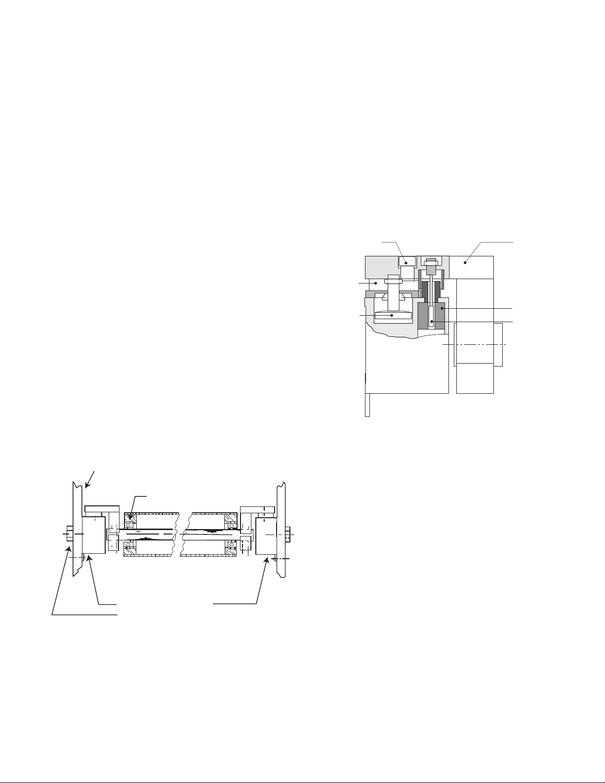
The Mechanical System
The mechanical system consists of a Patented
"C-Flexure Pivot Assembly" which incorporates
a mounting Base Block, frictionless elastic pivot
(or hinge), and Load Plate. (See Figure 2) When a
mechanical force is applied to the Load Plate,
the pivot permits its deflection toward or away
from the Base Block.
Figure 2
Warner Electric • 800-825-9050 P-2012-4 • 819-0404
Type B - Bearings in Roll - Non-Rotating Shaft
Figure 1
3
Page 4
For our discussion here, deflection of the Load
Black - (2)
Red + (1)
Green (3)
Blue (4)
Input
Output
X Twisted Leads
A B
Oscillator Demodulator
P1
S1
S2
X
X
When Supplied
with Cable
(1) Red + DC
(2) Black – DC
(3) Green – Signal
(4) White + Signal
C D
BAC
D
Plate toward the Base Block is defined as the
"Compression Mode", while the opposite is
defined as the "Tension Mode". Tensioncells are
designed to operate equally well in either mode.
The Base Block contains an integral Mechanical
Stop to limit the amount of deflection in either
direction, and a Viscous Damper to allow
control of the tensioncell response to rapid
changes in apparent tension loads. (See Page 3,
Figure 2)
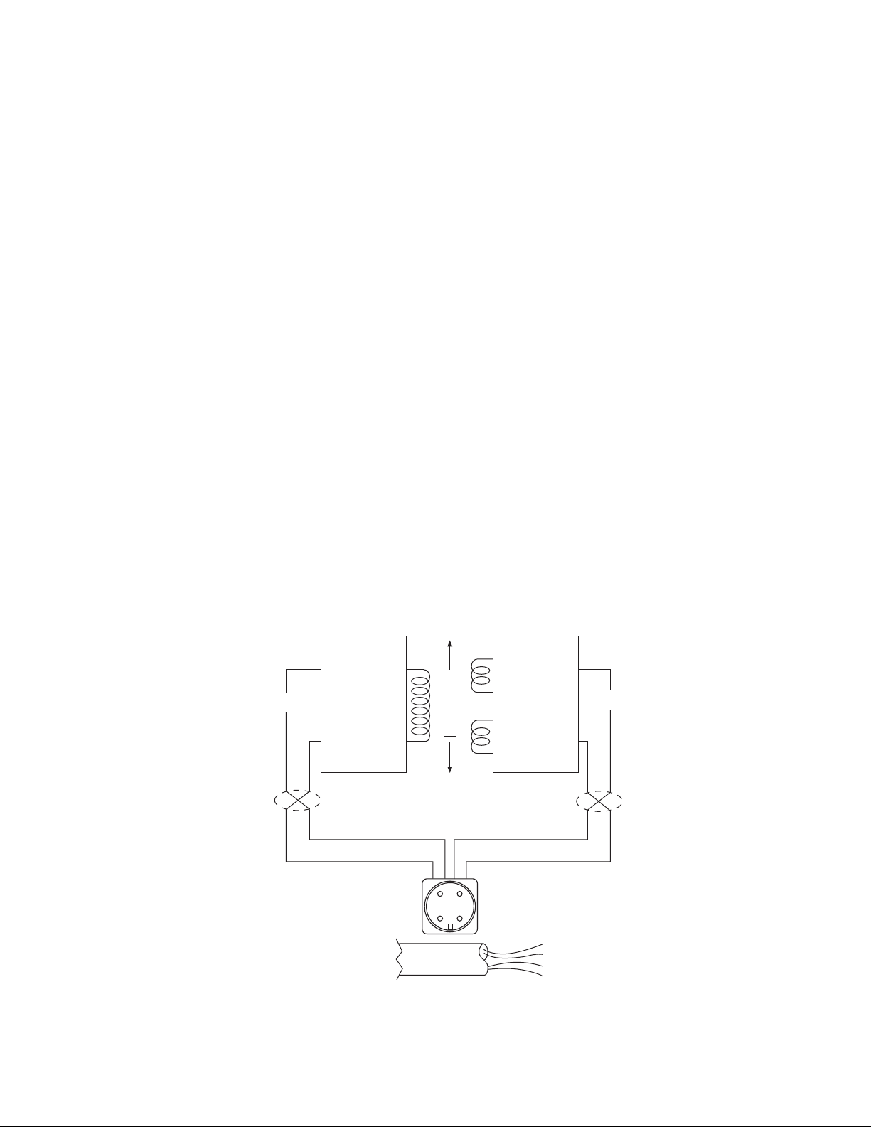
Type "K" DC LVDT
As illustrated in Figure 3, a DC LVDT consists of
the following components:
• An oscillator, which converts the DC input
voltage into a high frequency alternating
current for exciting the primary coil (P1)
• A Primary Coil (P1)
• A movable, permeable metallic core
• Two Secondary Coils (S1 and S2)
The Electrical System
The electrical system consists of a Linear
Variable Differential Transformer (LVDT) which
converts the mechanical deflection of the Load
Plate into a useful electrical output signal. (See
Figure 3.) The movable core of the LVDT is
mechanically coupled to the Load Plate by
means of the Core Adjust Assembly. (See
Figure 3) This adjustment is factory set and is
not accessible.
• A demodulator and summing network to
rectify and integrate the currents from the
Secondary Coils
Figure 3
Warner Electric • 800-825-9050 P-2012-4 • 819-0404
4
Page 5
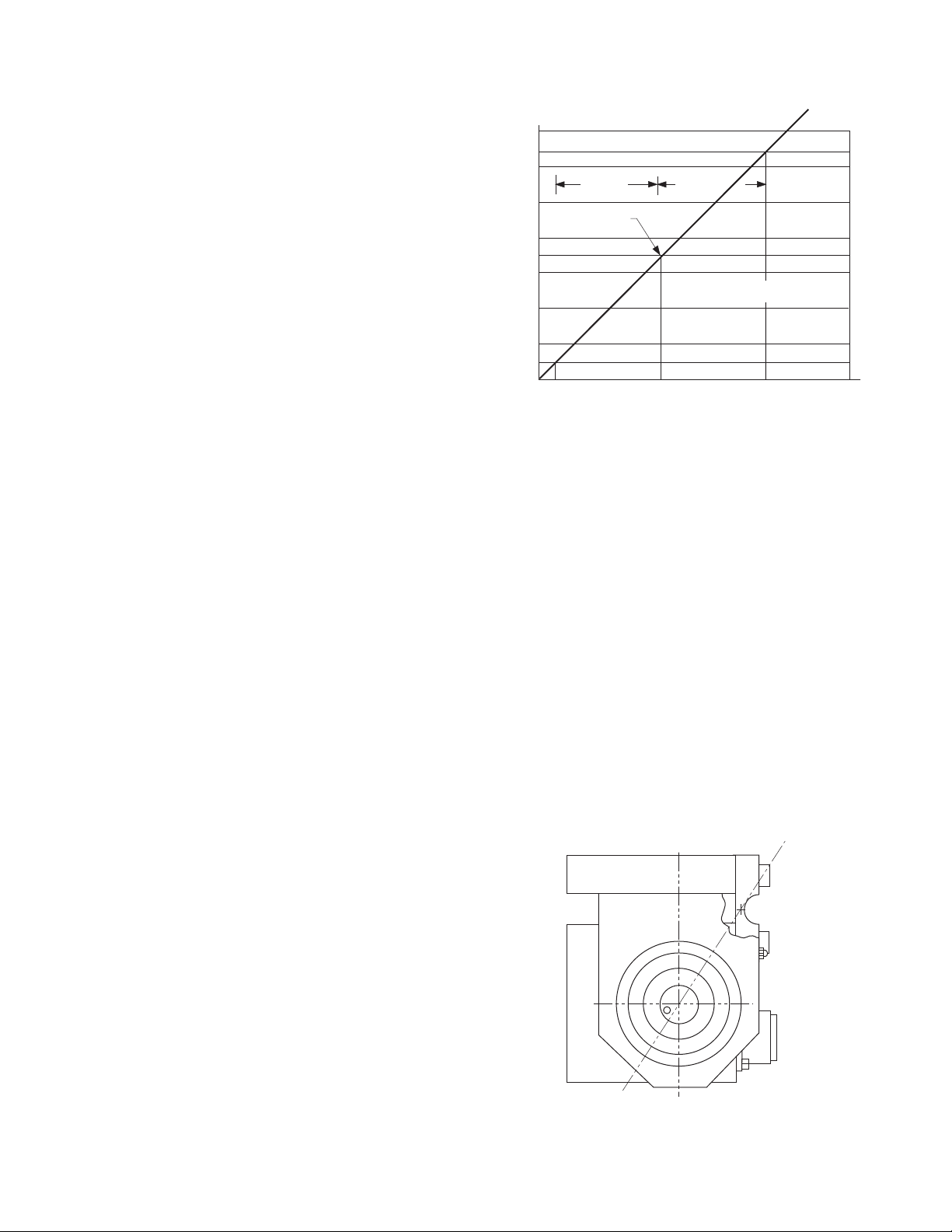
7
6
5
4
3
2
1
0
.030” 0.0 .030”
3.5 V. Set Point
Tension
Compression
LVDT Output vs Deflection
O
u
t
p
u
t
V
o
l
t
a
g
e
Deflection
With Warner Electric LVDTs, the input and
Nominal
L
R
output circuits are electrically isolated from each
other and from the mechanical structure of the
tensioncell. Thus, they may be used in "floating
ground" or "ground return" systems. This
eliminates the need for extra circuit boards
which are required for most straingage loadcells.
Tensioncells are factory adjusted to provide an
offset voltage with no load applied (no
deflection). Using an input of 24 volts DC, the
LVDT is set to provide an output of 3.5 volts into
a resistive load of not less than 100,000 ohms.
The voltage resulting from the maximum rated
deflection then adds to or subtracts from the 3.5
volt offset. This results in an output voltage of
3.5 to 6.5 volts in the Compression Mode and
3.5 to 0.5 volts in the Tension Mode. (See
Figure 4)
Figure 4
While acceptable performance may be obtained
over an input voltage range of 6.0 to 30.0 volts
DC, the output voltage will vary in direct
proportion to the input voltage. Because of
this, the use of a well regulated constant voltage
power supply is essential for accurate and
repeatable tension measurement.
In standard applications, where two Tensioncells
are used, the inputs may be connected in
parallel allowing the Tensioncells to be excited
from the same power supply. The LVDT outputs
are then summed to obtain a signal representing
the strip tension and tare loads distributed
across the roll.
Warner Electric • 800-825-9050 P-2012-4 • 819-0404
Description of Operation
The total resultant load per cell (RF) is calculated
by resolving all force vectors acting upon the
Tensioncell, with respect to the Loading Line
(OL). (RF) is the resultant of both TENSION and
TARE loads, PER CELL!! (See Figure 5)
The intrinsic design of Warner Electric Tensioncells allows the location of the Resultant Load of
Strip Tension (H) on any angle with respect to
the Load Line (OL). Note, however, that the Total
Force vector (RF) must always be calculated on
the line (OL).
Figure 5
5
Page 6

N
TW
D
T
T
H
RF
E
E
Figure 6A
Figure 6B
T
T
TW
RF
N
D
H
E
E
N
T
T
E
E
H
RF
D
TW
Figure 7B
N
TW
E
E
H
T
RF
T
D
Figure 7A
The intrinsic design of Warner Electric
Tensioncells allows the location of the Resultant
Load of Strip Tension (H) on any angle with
respect to the Load Line (OL). Note, however,
that the Total Force vector (RF) must always be
calculated on the line (OL).
Any force vector falling on the line (OR) (through
the pivot point of the C-Flexure) will produce no
deflection, and thus no change in electrical
output.
Rotating the Tensioncell on its mounting bolt
changes the force vectors on the cell. This
feature makes it possible to minimize the tare
component and maximize the load signal
output.
The resultant tare is minimized by mounting the
Tensioncell so that (N) is 149° (See Figures 6A
and 6B) or so that (N) is 329° (See Figures 7A
and 7B).
Warner Electric • 800-825-9050 P-2012-4 • 819-0404
6
Page 7

Installation and Operation
1.63
1.06
.25 Dia.
5/8-11 UNC
1.06
W1
W2
Inspection Upon Delivery
Warner Electric Tensioncells are carefully
packaged in sturdy reinforced cartons or
wooden boxes and are securely blocked or
bolted in place.
1. Upon receipt, examine the exterior of the
container for obvious damage or tampering.
2. Check the contents against the packing list.
3. Promptly report any damage or shortage to
both the carrier and Warner Electric.
Handling
Tensioncells can be handled manually.
Warner Electric Wall Mounted Tensioncells are
mounted to the machine frame by a 5/8-11 UNC
bolt which is in line with the centerline of the
measuring roll shaft. This allows the Tensioncell
to be rotated around the centers of the
measuring roll and mounting bolt to achieve the
proper mounting angle (Description of Operation
on Page 5).
The locating tab prevents the Tensioncell from
rotating and secures it in a permanent location.
It also provides a means of repeating rotary
position when the Tensioncell needs
replacement.
NOTE: Remove the 1/4" locking screw and
the 5/8" mounting bolt. This permits the roll
assembly with Tensioncells to be lifted out
of the machine.
Long Term Storage
While Warner Electric loadcells are plated,
exposure to weather, dirt, or moisture should be
avoided when they are stored.
Mechanical Installation
NOTE: Refer to the Dimension Drawing
Pages 11 and 12 of this manual for detailed
identification of all parts.
Tensioncells are designated as W1 and W2, one
being the mirror image of the other to provide for
mounting between two fixed walls.
(See Figure 8)
To install Tensioncells:
1. Make sure a 5/8” diameter hole is drilled
through the machine frame in line with the
centerline of the measuring roll shaft for the
5/8-11 UNC mounting bolt.
2. Fasten the Tensioncell to the machine frame
with the mounting bolt.
3. Rotate the Tensioncell to the proper
mounting angle and tighten the mounting
bolt. (Refer to N on the calibration sheet for
the proper mounting angle.
4. Drill a #6 (.204) hole concentric with the 1/4"
hole in the locating tab.
5. Remove the Tensioncell and tap the hole for
a 1/4-20 thread.
6. Repeat steps 1 through 5 for the Tensioncell
to be mounted at the other end of the
measuring roll.
7. Assemble the tensioncells onto the ends of
the measuring roll shaft.
Figure 8
Warner Electric • 800-825-9050 P-2012-4 • 819-0404
7
Page 8

8. Position the roll with the Tensioncells on the
Black - (2)
Red + (1)
Green (3)
Blue (4)
Input
Output
X Twisted Leads
A B
Oscillator Demodulator
P1
S1
S2
X
X
When Supplied
with Cable
(1) Red + DC
(2) Black – DC
(3) Green – Signal
(4) White + Signal
C D
BAC
D
machine and fasten with the mounting bolts.
Specifications
9. Rotate the Tensioncells to the proper
mounting angle and tighten the mounting
bolts.
10. Lock the locating pad for each Tensioncell
against the machine frame using the 1/4-20
x 1/2 socket head capscrew.
11. Tighten the shaft in the mounting block on
the W1 unit. (The shaft end at W2 is left free
to allow it to move as the shaft expands with
temperature changes).
Mechanical Alignment
Align the sectional measuring roll to avoid any
mechanical binding or friction. The measuring
roll must be level and perpendicular to the path
of the strip material for accurate measurement.
The Mechanical Stops are fixed for the required
travel of the Load Table.
Type "K" 24 volt DC LVDT Specifications
Input . . . . . . . . . . . . . . . . . . . . . . . . .6-30 volts DC
Output . . .0.5-6.5 volts DC (nominal, open circuit)
Output Impedence . . . . . . . . . . . . . . . .2.5K ohms
Current Consumption . . . . . . . . . . . . . . . . .40 mA
Recommended Load . . . . . .100K ohms or greater
Max. Operating Temp . . . . . . . . . . . . . . . . . .250°F
NOTE: Warner Electric loadcells are calibrated
for 24 volt DC input voltage to provide a 0.5 to
6.5 volts DC output signal.
Electrical Installation
(Read the entire electrical wiring procedure
before proceeding.)
1. Turn off all electrical power to the loadcell.
2. Use twisted four conductor signal cable,
Belden 9402 or equivalent, in grounded steel
conduit from the LVDTs to the control panel.
3. Observing correct polarity, connect the
positive (+) input lead to Pin A and the
negative (-) input lead to Pin B.
(See Figure 9)
4. Connect the positive (+) output lead to Pin D
and the negative (-) output lead to Pin C.
(See Figure 9)
5. Repeat Steps 1 through 4 of the electrical
wiring procedure for the Tensioncells
mounted on the other end of the measuring
roll.
Figure 9
Electrical Zero Adjustment
(Read the complete Electrical Zero Adjustment
procedure before proceeding with the
adjustment.)
1. Disengage strip from the measuring roll so
that no tension force is applied to the
loadcell.
2. Connect a voltmeter to Pins C and D
(See Figure 9)
Warner Electric • 800-825-9050 P-2012-4 • 819-0404
8
Page 9

3. Apply 24 volt DC electrical power to the
Roll
Rope
Web Path
Weights for
Max. Tension
loadcell observing the correct polarity. [Plus
(+) to Pin A and minus (-) to Pin B.] Do not
exceed the maximum rated input voltage.
NOTE: Allow 20 minutes for the loadcell to
warmup before taking first readings to insure
accurate readings.
4. Measure the output voltage of the LVDT
between the Green and White leads for
each tensioncell with a volt meter with a
sensitivity of at least 100,000 ohms per volt.
The output voltage should be between 0.5
and 6.5 volts.
3. With a voltmeter connected to Pins C and D
of the connector, an output voltage will be
observed.
4. Repeat Step 3 for the Tensioncell mounted
on the opposite end of the measuring roll.
Warner Electric Ioadcells instrumentation
provides the required signal conditioning and
a reliable high level output signal for use as
feedback control of a tension drive system. The
feedback signal is directly proportional to the
strip tension applied. If a Warner Electric control
is used, refer to the control manual for further
calibration.
5. Since Warner Electric Tensioncells cannot be
mechanically zeroed, refer to the Control
Manual for zeroing out the tare weight
voltage.
Full Load Adjustment
After the loadcell has been zeroed, a pull test
can be made to check the output voltage of the
loadcell at full load. (See calibration sheet for
voltage output.)
1. Run a non-stretchable rope over the center
of the tension roll simulating the web path.
(Note: The rolls should be free to turn.)
2. With one end of the rope secured, hang a
known weight equally over the roll so that
the total tension is equal to the maximum
strip tension specified on the calibration
sheet, at the other end. (See Figure 10)
Although the electrical output of Warner Electric
tensioncells are sufficient to drive most electrical
indicators, substantial signal conditioning is
normally required for effective tension
instrumentation system control. Refer to the
documentation available from the
instrumentation supplier for more information.
Troubleshooting
When properly installed in accordance with the
original design specifications Warner Electric
tensioncells should require little or no regular
maintenance or service.
Certain conditions, however, can impair their
inherently accurate and reliable performance.
Therefore, if trouble should arise, the following
conditions should be checked. (Continued on
next page)
Warner Electric • 800-825-9050 P-2012-4 • 819-0404
Figure 10
9
Page 10

Mechanical
Black - (2)
Red + (1)
Green (3)
Blue (4)
Input
Output
X Twisted Leads
A B
Oscillator Demodulator
P1
S1
S2
X
X
When Supplied
with Cable
(1) Red + DC
(2) Black – DC
(3) Green – Signal
(4) White + Signal
C D
BAC
D
1. Has the tension measuring system been
changed?
a. An increase or decrease in strip tension
(Refer to A on the calibration sheet for
specified strip tension.)
b. An increase or decrease in the wrap angle.
(Refer to B on the calibration sheet for the
specified wrap angle.)
If the above parameters have been changed
enough to prevent the unit from operating within
the limits of the fixed. Mechanical Stops,
replacement of the tensioncells required. For
this modification, the Tensioncell should be
returned to the factory with complete
specifications.
2. Are the loadcells mounted securely?
c. Pin C to Pin D (Secondary Coil) should be
approximately 20,000 ohms.
d. Pin C or Pin D to LVDT shell should be in
excess of 5 megohms.
If LVDT circuits are open or shorted, replace the
Tensioncell LVDT. Contact Warner Electric with
Tensioncell model number and serial number.
Recalibration after Installation
Wall Mounted Tensioncells can be relocated
around the center of the measuring roll. The
theory of this operation is explained in the
Description of Operation on Page 5. If this
procedure cannot accomplish the necessary
changes because the tension requirements are
extremely different than the original application,
it will be necessary to return the Tensioncells to
the factory for a different Tensioncell.
3. Is tension measuring roll in proper alignment
and does it turn freely?
4. Are bearings and seals free of all binding and
stickiness? Are they worn?
Electrical
1. Are LVDTs receiving correct input voltage?
Check line voltage, fuses or circuit breakers,
and power switches. Check power supply
output and voltage to LVDTs.
2. Are all connections secure?
Check for continuity. Retighten all
connections. Recheck operation.
3. Are LVDTs open or shorted?
To check, turn off power and disconnect the input
and output leads. Check coil continuity and
resistance. (Refer to Figure 11)
Figure 11
a. Pin A to Pin B (Primary Coil) should be in
Warner Electric • 800-825-9050 P-2012-4 • 819-0404
10
excess of 2 megohms.
b. Pin A or Pin B to LVDT shell should be in
excess of 5 megohms.
Page 11

Model Number Nomenclature Example
Electrical
Connection
B - MS Connector
Series Number (2 Digits)
30 Wall Mount
K - DC LVDT with
Maximum 3 VDC Output
Change Including Tare
Displacement
B B 3 0 P 1 6 K W1
Type
B - Non-Rotating Shaft
Capacity Range
Shaft Diameter
Shaft Mounting Configuration
W1-Split bushing
W2-Solid bushing
Series 30, Type B Specifications – Non-Rotating Shaft Mounting
See Table II-A
See Table ll-B
Example Shown:
BC30P16KW1
N = MS Connector
C = Rotating Shaft
30 = Series 30, Wall Mount
P = 0-20 lbs. Capacity
16 = 1” Diameter Shaft
K = K Type DC LVDT
W1 = Split Bushing
Series 30, Type B – Nominal Capacity Ranges
Code P T U X Z
Pounds 0-20 0-50 0-90 0-200 0-500
Table II-A
Note: Other Load ranges are available on special order. Contact Warner Electric for ratings & abalability.
**Warner Electric wall mounted tensioncells are located by a 5/8-11 bolt at the roll centerline and locating tab which
maintains rotational position of the tensioncell. (See Page 6.)
Notes:
W1 unit shown here.
W2 unit is applied at the opposite end of the roll.
W1 unit clamps the shaft while W2 allows for
temperature expansion of the roll.
Both units have self-aligning feature.
Series 30, Type B Shaft Diameter Code
Code 12 16 20 23
Inches 3/4 1.0 1-1/4 1-7/16
RH 1.00 1.13
Warner Electric • 800-825-9050 P-2012-4 • 819-0404
11
Page 12

4-Pin Connector
Mounting
**5/8-11
3.75
2.88
3.63
2.31
RH
2.44
1.56
1.63
1.06
1.82
3.13
.94
.25 DIA Hole Thru
**Warner Electric wall mounted tensioncells are located by a 5/8-11 bolt at the roll centerline and locating tab which
maintains rotational position of the tensioncell. (See Page 6.)
Notes:
W1 unit shown here.
W2 unit is applied at the opposite end of the roll.
W1 unit clamps the shaft while W2 allows for
temperature expansion of the roll.
Both units have self-aligning feature.
Series 30, Type B Shaft Diameter Code
Code 12 16 20 23
Inches 3/4 1.0 1-1/4 1-7/16
RH 1.00 1.13
Note: Other shaft diameters are availible in special order.
Contact Warner Electric for other shaft diameter avalibility.
Table II-B
12
Warner Electric • 800-825-9050 P-2012-4 • 819-0404
Page 13

Warner Electric • 800-825-9050 P-2012-4 • 819-0404
13
Page 14

Warranty
Warner Electric LLC warrants that it will repair or replace (whichever it deems advisable) any
product manufactured and sold by it which proves to be defective in material or workmanship
within a period of one (1) year from the date of original purchase for consumer, commercial or
industrial use.
This warranty extends only to the original purchaser and is not transferable or assignable without
Warner Electric LLC’s prior consent.
Warranty service can be obtained in the U.S.A. by returning any defective product, transportation
charges prepaid, to the appropriate Warner Electric LLC factory. Additional warranty information
may be obtained by writing the Customer Satisfaction Department, Warner Electric LLC,
449 Gardner Street, South Beloit, Illinois 61080, or by calling 815-389-3771.
A purchase receipt or other proof of original purchase will be required before warranty service is
rendered. If found defective under the terms of this warranty, repair or replacement will be made,
without charge, together with a refund for transportation costs. If found not to be defective, you will
be notified and, with your consent, the item will be repaired or replaced and returned to you at
your expense.
This warranty covers normal use and does not cover damage or defect which results from
alteration, accident, neglect, or improper installation, operation, or maintenance.
Some states do not allow limitation on how long an implied warranty lasts, so the above limitation
may not apply to you.
Warner Electric LLC’s obligation under this warranty is limited to the repair or replacement of the
defective product and in no event shall Warner Electric LLC be liable for consequential, indirect,
or incidental damages of any kind incurred by reason of the manufacture, sale or use of any
defective product. Warner Electric LLC neither assumes nor authorizes any other person to give
any other warranty or to assume any other obligation or liability on its behalf.
WITH RESPECT TO CONSUMER USE OF THE PRODUCT, ANY IMPLIED WARRANTIES WHICH
THE CONSUMER MAY HAVE ARE LIMITED IN DURATION TO ONE YEAR FROM THE DATE OF
ORIGINAL CONSUMER PURCHASE. WITH RESPECT TO COMMERCIAL AND INDUSTRIAL
USES OF THE PRODUCT, THE FOREGOING WARRANTY IS IN LIEU OF AND EXCLUDES ALL
OTHER WARRANTIES, WHETHER EXPRESSED OR IMPLIED BY OPERATION OF LAW OR
OTHERWISE, INCLUDING, BUT NOT LIMITED TO, ANY IMPLIED WARRANTIES OF
MERCHANTABILITY OR FITNESS.
Some states do not allow the exclusion or limitation of incidental or consequential damages, so the
above limitation or exclusion may not apply to you. This warranty gives you specific legal rights and
you may also have other rights which vary from state to state.
Changes in Dimensions and Specifications
All dimensions and specifications shown in Warner Electric catalogs are subject to change without
notice. Weights do not include weight of boxing for shipment. Certified prints will be furnished
without charge on request to Warner Electric.
Warner Electric LLC
31 Industrial Park Road • New Hartford, CT 06057
815-389-3771 • Fax: 815-389-2582
www.warnerelectric.com
P-2012-4 • 819-0404 6/12 Printed in USA
 Loading...