

Page 1
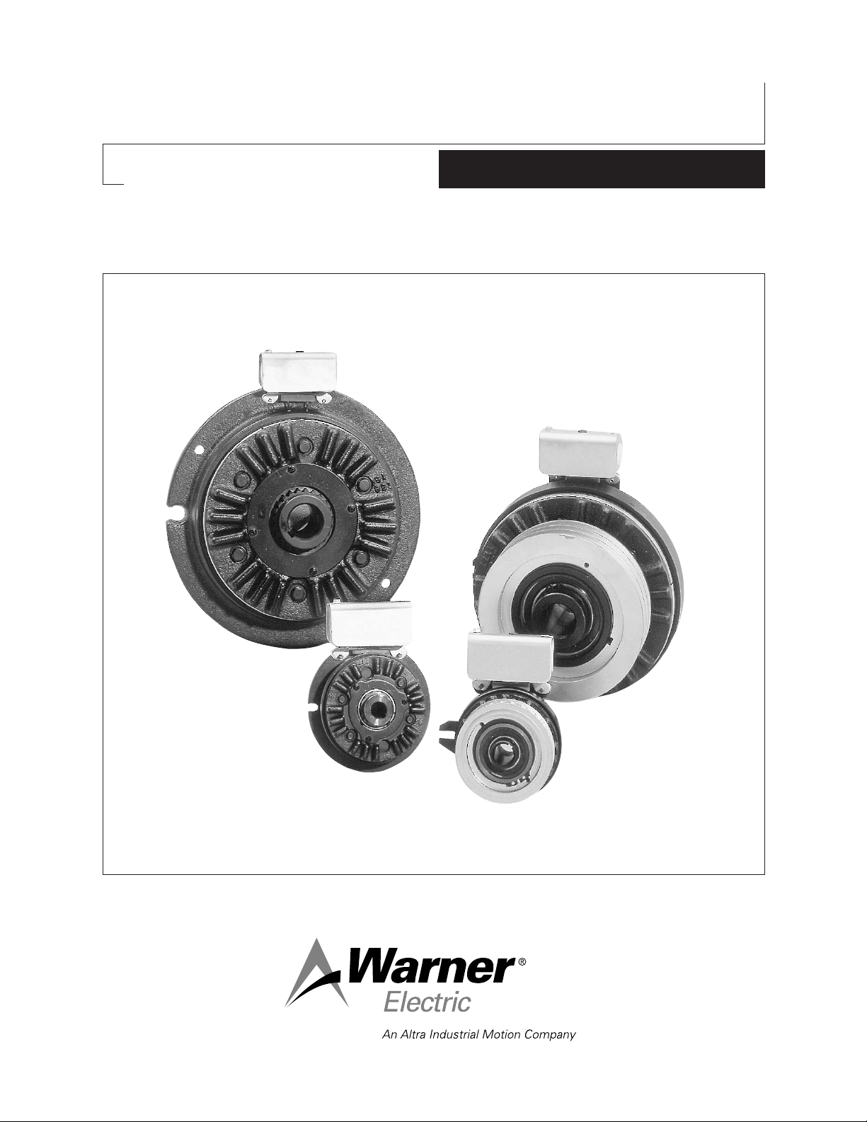
ATT Tension Brakes
P-221
819-0338
Installation Instructions
Page 2

Contents
Introduction . . . . . . . . . . . . . . . . . . . . . . . . . . . . .2
Installation . . . . . . . . . . . . . . . . . . . . . . . . . . . . . .4
Wear Indication . . . . . . . . . . . . . . . . . . . . . . . . . .5
Brake Repair on the Shaft . . . . . . . . . . . . . . . . . .6
Troubleshooting . . . . . . . . . . . . . . . . . . . . . . . . . .8
Dimensions and Specifications . . . . . . . . . . . . . .9
Exploded View and Parts Lists . . . . . . . . . . . . .10
Warranty . . . . . . . . . . . . . . . . . . . . . . . .back cover
Failure to follow these
instructions may result in product damage,
equipment damage, and serious or fatal injury
to personnel.
Introduction
The Warner Electric AT Tension (ATT) brake you
have purchased has been designed to provide
long and trouble free service. It is a rugged and
durable unit which is rebuildable with friction face
replacement kits discussed in this service manual.
The friction face replacement kit renews the friction
surfaces.
This service manual includes instructions required
for installation, repair on the shaft, and
troubleshooting information, specifications,
dimensions, an exploded view and parts lists.
Please refer to the Table of Contents for section
page numbers.
All installation and repair involving ATT brakes must
be carried out in accordance with the procedures
specified in the service manual. All stated or
implied manufacturer warranties are voided if this
product is not installed and serviced in accordance
with these instructions.
Warner Electric • 800-825-9050 P-221 • 819-0338
2
Page 3
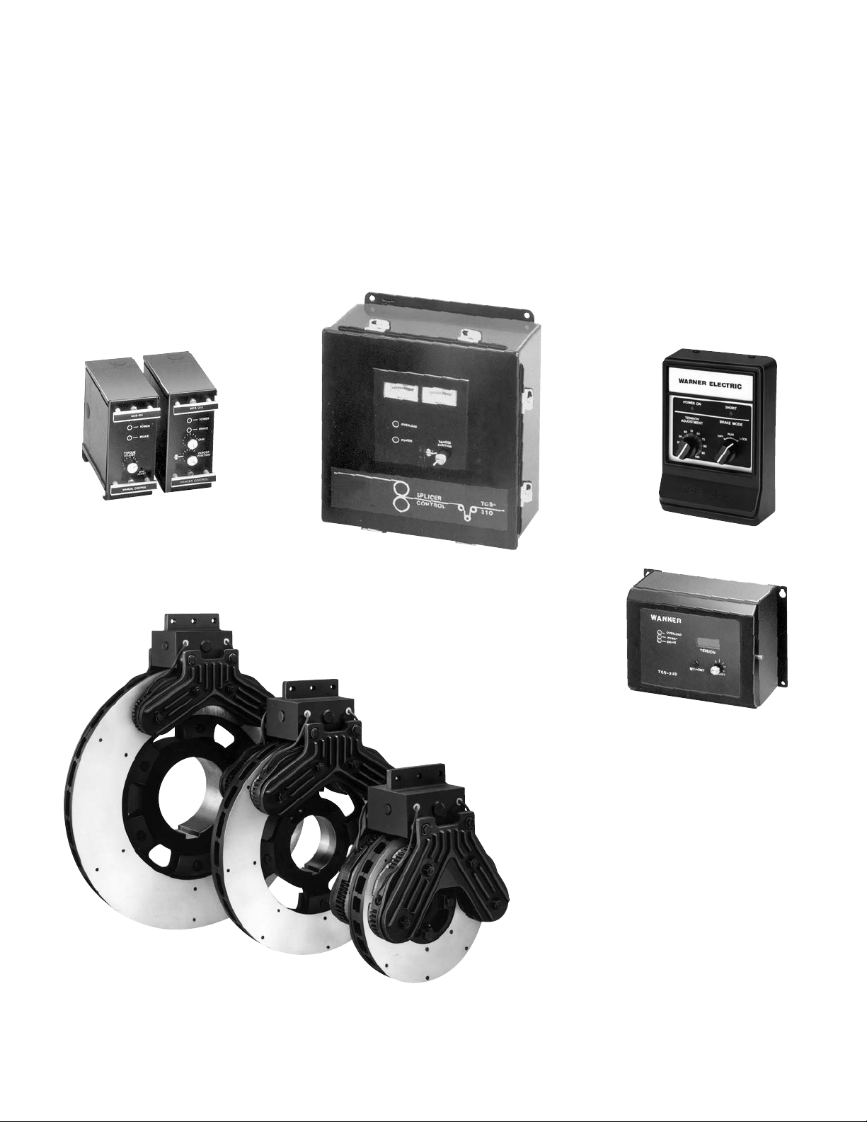
Other Tensioning Products
Warner Electric offers many tension control
products in addition to the ATT line. Basic tension
brakes and high performance modular tension
brakes are available, as well as a complete line of
electronic tension controls. These include a basic
manual control, a load cell control, a closed loop
dancer control, and splicer controls. For more
information on these and other products, please
call or write:
Warner Electric
31 Industrial Park Road
New Hartford, CT 06057
Phone (815) 389-3771
Modular control systems for
tension brakes are either manual
adjust or closed loop types.
Simple tension control
requires only a tension
brake and this manual
control.
Splicer control offers dual functions for
two roll systems requiring simultaneous
tensioning and holding.
Load cell control system
automatically adjusts
tension from load cell
amplifier input.
Modular tension brakes are
available in 10", 13", 15", and
20" diameters with single or
dual friction discs and two to
twelve magnets.
Warner Electric • 800-825-9050 P-221 • 819-0338
3
Page 4
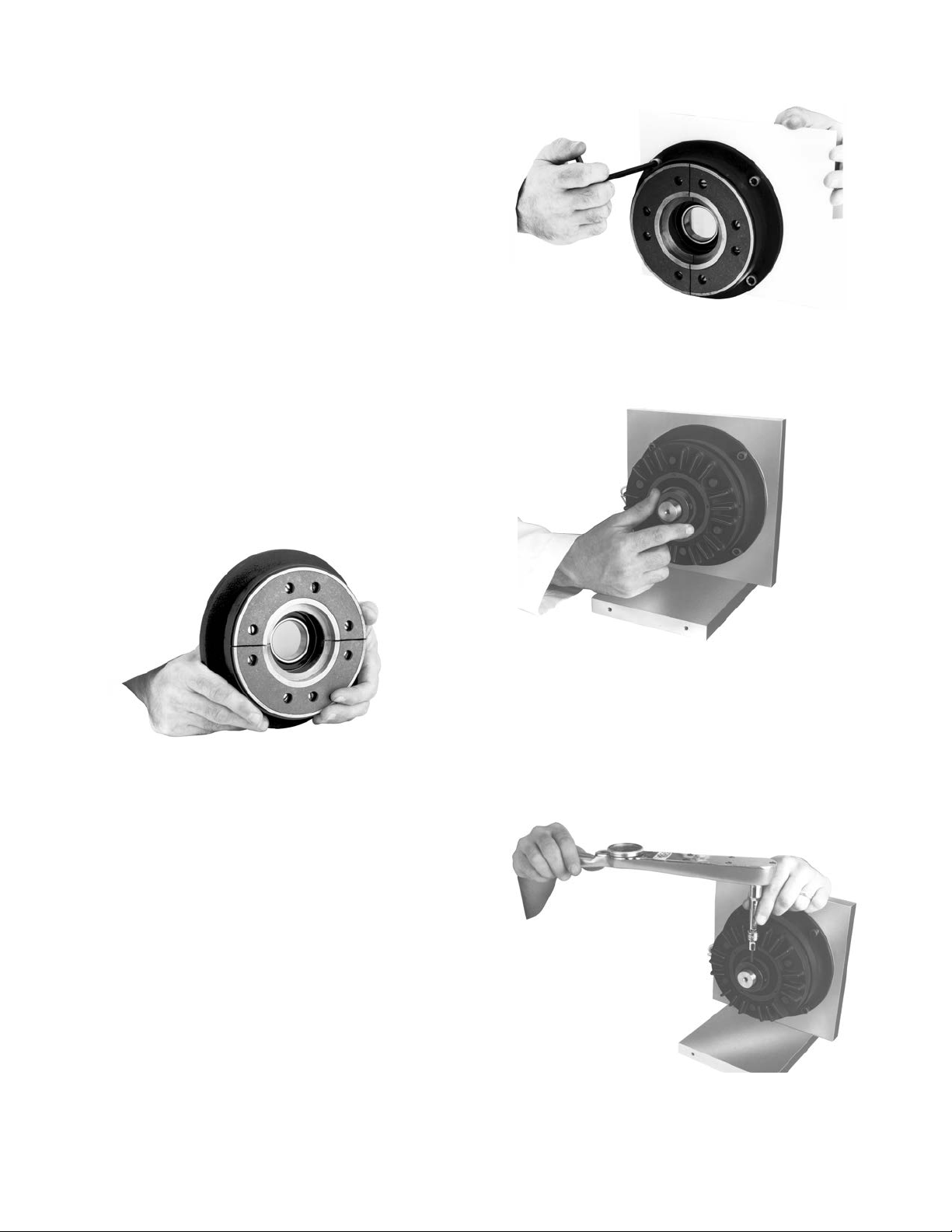
Brake Installation
1. Remove your ATT brake from its shipping
carton and inspect it thoroughly to ensure
that is has arrived in good condition.
An accessory kit included with your brake
contains a coil wire retainer and mounting
hardware.
2. If used, install the Warner Electric conduit box
in accordance with its furnished instructions.
3. Mount the magnet to the machine frame
using the hardware in the accessory kit so
that the magnet face is square with the
armature shaft within .006 T.I.R. and the
magnet mounting pilot diameter is concentric
with the armature shaft within .010 T.I.R.
This is important to assure proper
function and unit life.
5. Slide the armature over the input hub.
6. Slide the hub onto the shaft and provide a
1/16" gap between the friction faces.
4. Tighten the mounting screws to the machine
frame to the appropriate torque for your size
brake.
Size Torque
25 12.5 ft.-lbs.
55 25 ft.-lbs.
115 25 ft.-lbs.
7. Tighten the set screws located in the hub to
the appropriate torque for your size unit:
Size Torque
25 80 in.-lbs.
55 160 in.-lbs.
115 275 in.-lbs.
Warner Electric • 800-825-9050 P-221 • 819-0338
4
Page 5

8. When using a Warner Electric tension control,
follow the connection diagram supplied with
the control.
If a Warner Electric TCS-210, -220, -310, or
320 control is used, add a 68 ohm resistor
across the sense circuit. Although the TCS
series controls are recommended, a MCS
control can be used with normal hook-up.
Wear Indication
Your ATT brake should be visually inspected on a
periodic basis to determine if the wearing surfaces
warrant replacement. The friction face and
armature should be replaced when the armature
reaches the wear indicator on the magnet shell. If
replacement is not made at this time, further use
will wear into the screw heads making removal and
replacement of the friction facing difficult.
The drawing below illustrates the area to be
inspected.
9. Your ATT brake is now ready for its static test.
Apply DC voltage to the coil through the
brake control. The armature should pull
against the friction material face.
10. Run the brake under its operating load.
11. Your ATT brake may not achieve its full torque
until after a short “break-in” period. To break
in the brake, cycle it on and off under full load
at operating speed a minimum of ten times in
quick succession.
Your ATT brake is now ready to run.
When the friction surfaces are worn to this point,
replace with the appropriate friction face
replacement kit. All of the components needed to
refurbish the wearing surfaces of your brake are
provided in the replacement kit.
ATT-25 5161-101-008
ATT-55 5162-101-008
ATT-115 5163-101-008
Warner Electric • 800-825-9050 P-221 • 819-0338
5
Page 6

Complete Brake Repair–On The Shaft
The new ATT design incorporates a rugged, durable
design for long life and maximum heat dissipation.
Easy-to-replace friction surfaces extend the design
life for continued like-new performance. The ATT
offers complete repair-on the shaft following ten
easy steps. The repair can be completed utilizing
the parts in the friction face replacement kit.
1. Move the brake armature away from the
magnet for disassembly and reassembly.
2. Remove the hex head cap screws, washers
and lockwashers to loosen the armature
segments from the cast iron carrier.
6. Insert two new friction material segments.
The recessed holes should be facing away
from the magnet body.
3. Lift out the two worn armature segments.
4. Remove the screws which attach the friction
material segments to the brake magnet
through the appropriate access holes.
5. Lift the worn friction material segments.
7. Attach the new friction material segments
to the brake with the screws through the
appropriate access holes. Apply one drop of
Loctite (grade 290 or equivalent) to each
screw.
Warner Electric • 800-825-9050 P-221 • 819-0338
6
Page 7

Note: Use only the screws included with
the repair kit since any other screws may
damage the unit. Tighten to 18 to 22 lb. in.
torque.
8. Insert the two new armature segments.
9. Attach the new armature segments to the
cast iron carrier with hex cap screws,
lockwashers and washers. Apply one drop of
Loctite (grade 290 or equivalent) to each
screw. Tighten to the appropriate torque for
your size unit.
Size Torque
ATT 25 29-35 in.-lbs.
ATT 55 60-84 in.-lbs.
ATT 115 60-84 in.-lbs.
10. Ensure there is a 1/16" gap between the
friction faces.
11. Your ATT brake is now ready for its static
test. Apply DC voltage to the coil through
the brake control. The armature should
pull against the friction material face with
an audible “click”.
12. Run the brake under its operating load.
13. Your ATT brake may not achieve its full torque
until after a short “break-in” period. To break
in the brake, cycle it on and off under full load
at operating speed a minimum of ten times in
quick succession.
Your ATT brake is now ready to run.
Warner Electric • 800-825-9050 P-221 • 819-0338
7
Page 8

ATT Brake Troubleshooting Guide
In performance problems are present after carefully following the instructions in this manual, use the following
check list.
Symptom Check
Brake armature will not move or • Coil Resistance
engage when power is applied Coil may be open. See Chart 1.
to the coil. • Power Supply
Assure proper DC voltage is being delivered to the brake.
• Airgap
If greater than 3/32" gap around entire periphery, reset.
Vibration • Runout
Assure that shaft on which the clutch is mounted doesn’t have excessive runout.
• Shaft Engagement
Assure adequate shaft length and diameter engagement in the hub.
Low Tension • Power Supply
Assure proper DC voltage is being delivered to the brake.
• Adequate Burnishing
Unit must be run and cycled a few times to achieve full rated torque.
• Friction Surfaces
Replacement may be required.
• Installation of replacement friction material or armature segments may be
incorrect and not allow full contact.
Clutch/Brake Coil Approx. Coil
Size Voltage Resistance (Ohms)
25 24 20.6
25 90 290
55 24 19.6
55 90 230
115 24 16.5
115 90 182
Chart 1
Warner Electric • 800-825-9050 P-221 • 819-0338
8
Page 9

Electric Brakes and Clutches
ATT Series – Advanced Technology Brakes and Clutches
D
Customer shall maintain:
1. Squareness of brake mounting face with
armature hub shaft within .006 T.I.R.
Shaft Bore and
Keyway Dimensions
Model Unit Bore Key
ATTB-25
ATTB-25
ATTB-25 .7525 19.11
ATTB-55 .7505 19.06
ATTB-25 .8775 22.29
ATTB-55 .8755 22.24
( ) denotes millimeters
Model Max. Nom. Max. Dia. Dia. Nom. Max. Nom. Max.
ATTB-25
ATTB-55
ATTB-115
.5025 12.76
.5005 12.71
.6275 15.94
.6255 15.89
( )
( )
( )
( )
DE F G H J L M P
1.347 4.748 3.767 5.250 5.625/5.623 1.544 .225 3.586 2.080
(34.21) (120.60) (95.68) (133.35) (142.87/142.82) (39.22) (5.71) (91.08) (52.83)
1.770 5.37 3.767 6.875 7.373/7.375 1.544 .491 4.208 3.105
(44.96) (136.40) (95.68) (174.62) (187.27/187.33) (39.22) (12.47) (106.88) (78.87)
2.152 6.278 3.767 8.500 9.000/8.998 1.544 .463 5.116 3.105
(54.66) (159.46) (95.68) (215.90) (228.60/228.55) (39.22) (11.76) (129.95) (78.87)
1/8 Sq.
3/16 Sq.
3/16 Sq.
3/16 Sq.
Model Unit Bore Key
ATTB-55 1.0025 25.46 1/4 Sq.
1.0005 25.41
ATTB-55 1.1275 28.64 1/4 Sq.
ATTB-115 1.1255 28.59
ATTB-115 1.2525 31.81 1/4 Sq.
1.2505 31.76
ATTB-115 1.7775 34.99 5/16 Sq.
1.3755 34.94
ATTB-115 1.5025 38.16 3/8 Sq.
1.5005 38.11
2. Concentricity of brake mounting pilot diameter
with armature hub shaft within .010 T.I.R.
ABC
Max. Min.
Model Dia. Max. Dia.
ATTB-25
ATTB-55
ATTB-115
Pilot
4.822 2.730 .264
(122.48) (69.34) (6.70)
6.271 3.010 .330
(159.28) (77.97) (8.38)
7.906 3.625 .330
(200.81) (12.07) (8.38)
For replacement parts list and exploded view drawing, see page 10.
Warner Electric • 800-825-9050 P-221 • 819-0338
9
Page 10

Brake Assemblies and Part Numbers
ATT Series – Advanced Technology Brakes
ATTB-25, ATTB-55, ATTB-115
Brake Assemblies
Unit Size Voltage Part No.
ATTB-25-1/2 24 5191-6
ATTB-25-1/2 90 5191-10
ATTB-25-5/8 24 5191-7
ATTB-25-5/8 90 5191-11
ATTB-25-3/4 24 5191-8
ATTB-25-3/4 90 5191-12
ATTB-25-7/8 24 5191-9
ATTB-25-7/8 90 5191-13
ATTB-55-3/4 24 5192-6
ATTB-55-3/4 90 5192-10
ATTB-55-7/8 24 5192-7
ATTB-55-7/8 90 5192-11
Warner Electric • 800-825-9050 P-221 • 819-0338
10
Unit Size Voltage Part No.
ATTB-55-1 24 5192-8
ATTB-55-1 90 5192-12
ATTB-55-1-1/8 24 5192-9
ATTB-55-1-1/8 90 5192-13
ATTB-115-1-1/8 24 5193-6
ATTB-115-1-1/8 90 5193-10
ATTB-115-1-1/4 24 5193-7
ATTB-115-1-1/4 90 5193-11
ATTB-115-1-3/8 24 5193-8
ATTB-115-1-3/8 90 5193-12
ATTB-115-1-1/2 24 5193-9
ATTB-115-1-1/2 90 5193-13
Page 11

Part Numbers
Item ATTB-25 ATTB-55 ATTB-115
No. Description Qty. Part No. Qty. Part No. Qty. Part No.
1 Armature Hub 1 540-0908 1 540-0851 1 540-0864
2-1 Armature 1 110-0220 1 110-0218 1 110-0223
2-2 Facing Assem. 1 5191-445-003 1 5192-445-003 1 5193-445-003
2-3 Screw 6 797-1389 8 797-1389 8 797-1389
2-4 Screw 4 797-1020 6 797-1387 6 797-1174
2-5 Lockwasher –– 6 950-0355 6 950-0355
2-6 Flatwasher –– 2 950-0023 2 950-0023
3 Magnet Assem. 1– 1 – 1–
24 Volts D.C. – 5191-631-007 – 5192-631-007 – 5193-631-014
90 Volts D.C. – 5191-631-008 – 5192-631-008 – 5193-631-015
4 Splined Hub 1– 1 – 1 –
1/2" Bore – 5191-541-002 –– ––
5/8" Bore – 5191-541-003 –– ––
3/4" Bore – 5191-541-004 – 5192-541-002 ––
7/8" Bore – 5191-541-005 – 5192-541-003 ––
1" Bore –– – 5192-541-004 ––
1-1/8" Bore –– – 5192-541-005 – 5193-541-002
1-1/4" Bore –– – – –5193-541-003
1-3/8" Bore –– – –5193-541-004
1-1/2" Bore –– – – –5193-541-005
5 Mtg. Acc’y. 1 5191-101-007 1 5192-101-007 1 5192-101-007
Optional Accessory Items
6 Conduit Box 1 5162-101-002 1 5162-101-002 1 5162-101-002
Kit Items
7 Friction Face
Replacement Kit 1 5161-101-008 1 5162-101-008 1 5163-101-008
(includes items 2-1, 2-2, 2-3, 2-4, 2-5, 2-6)
Warner Electric • 800-825-9050 P-221 • 819-0338
11
Page 12

Warranty
Warner Electric LLC warrants that it will repair or replace (whichever it deems advisable) any
product manufactured and sold by it which proves to be defective in material or workmanship
within a period of one (1) year from the date of original purchase for consumer, commercial or
industrial use.
This warranty extends only to the original purchaser and is not transferable or assignable without
Warner Electric LLC’s prior consent.
Warranty service can be obtained in the U.S.A. by returning any defective product, transportation
charges prepaid, to the appropriate Warner Electric LLC factory. Additional warranty information
may be obtained by writing the Customer Satisfaction Department, Warner Electric LLC, 449
Gardner Street, South Beloit, Illinois 61080, or by calling 815-389-3771.
A purchase receipt or other proof of original purchase will be required before warranty service is
rendered. If found defective under the terms of this warranty, repair or replacement will be made,
without charge, together with a refund for transportation costs. If found not to be defective, you
will be notified and, with your consent, the item will be repaired or replaced and returned to you
at your expense.
This warranty covers normal use and does not cover damage or defect which results from
alteration, accident, neglect, or improper installation, operation, or maintenance.
Some states do not allow limitation on how long an implied warranty lasts, so the above limitation
may not apply to you.
Warner Electric LLC’s obligation under this warranty is limited to the repair or replacement of the
defective product and in no event shall Warner Electric LLC be liable for consequential, indirect,
or incidental damages of any kind incurred by reason of the manufacture, sale or use of any
defective product. Warner Electric LLC neither assumes nor authorizes any other person to give
any other warranty or to assume any other obligation or liability on its behalf.
WITH RESPECT TO CONSUMER USE OF THE PRODUCT, ANY IMPLIED WARRANTIES WHICH
THE CONSUMER MAY HAVE ARE LIMITED IN DURATION TO ONE YEAR FROM THE DATE OF
ORIGINAL CONSUMER PURCHASE. WITH RESPECT TO COMMERCIAL AND INDUSTRIAL
USES OF THE PRODUCT, THE FOREGOING WARRANTY IS IN LIEU OF AND EXCLUDES ALL
OTHER WARRANTIES, WHETHER EXPRESSED OR IMPLIED BY OPERATION OF LAW OR
OTHERWISE, INCLUDING, BUT NOT LIMITED TO, ANY IMPLIED WARRANTIES OF
MERCHANTABILITY OR FITNESS.
Some states do not allow the exclusion or limitation of incidental or consequential damages, so
the above limitation or exclusion may not apply to you. This warranty gives you specific legal
rights and you may also have other rights which vary from state to state.
Changes in Dimensions and Specifications
All dimensions and specifications shown in Warner Electric catalogs are subject to change
without notice. Weights do not include weight of boxing for shipment. Certified prints will be
furnished without charge on request to Warner Electric.
Warner Electric
31 Industrial Park Road • New Hartford, CT 06057
815-389-3771 • Fax: 815-389-2582
www.warnerelectric.com
P-221 • 819-0338 8/11 Printed in USA
 Loading...