

Page 1
ATT Brakes and Clutches
P-1407
819-0341
Rebuild Instructions
Page 2
Screw Driver
Access
P
Failure to follow these
instructions may result in product damage, equipment damage, and serious or
fatal injury to personnel.
Brake Repair – On the Shaft
Sizes 25, 55, 115
Friction Pads and Armatures
The new ATT design incorporates the latest in
advanced technology providing a rugged,
durable, patented design for long life, high cycle
rates and maximum heat dissipation. Patented,
easy-to-replace, friction surfaces extend the
design life for continued like-new performance.
The ATT offers complete repair on the shaft following ten easy steps. The repair can be completed utilizing the parts in the friction face
replacement kit. The unit shown is a brake, but
steps apply equally to clutch repair.
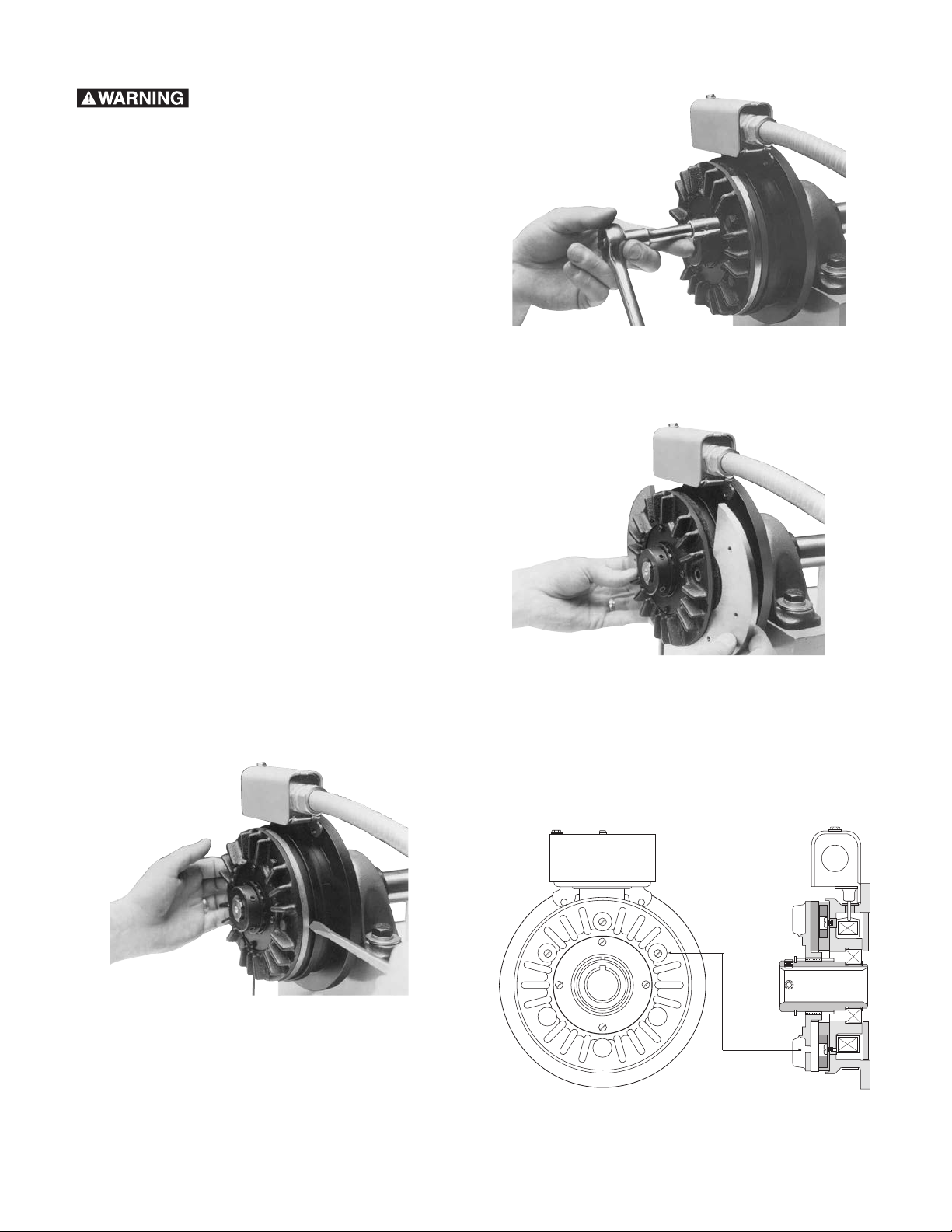
1. Move the brake or clutch armature away from
the magnet or field for disassembly and
reassembly.
a. Using a flat blade screwdriver, pry back
on armature assembly to increase airgap.
(See Figure 1)
Figure 2
3. Lift out the two worn armature segments.
(See Figure 3)
Figure 3
4. Remove the screws, which attach the friction
material segments to the brake magnet or
clutch rotor through the appropriate access
holes in armature face. (See Illustration A and
Figure 4)
Figure 1
2. Remove hex head capscrews, washers and
lockwashers to loosen the armature segments
from the cast iron carrier. (See Figure 2)
Warner Electric • 800-825-9050 819-0341
2
Illustration A
Page 3

Figure 4
5. Lift out the worn friction material segments.
Assure that the autogap plate, detent ring
and spring remain in place on the clutch units
during this step. (See Figure 5)
7. Attach the new friction material segments to
the brake magnet or clutch rotor with the
screws through the appropriate access holes.
®
Apply one drop of Loctite
‚ (grade AA equiva-
lent) to each screw. (See Figure 7) Note: Use
only the screws included with the repair kit
since any other screws may damage the
unit. Tighten screws to 18 to 22 inch
pounds torque.
Figure 5
6. Insert two new friction material segments.
The recessed holes should be facing away
from the magnet body. (See Figure 6)
Figure 7
8. Insert the two new armature segments. (See
Figure 8)
Figure 8
9. Attach the new armature segments to the
cast iron carrier with hex head capscrews,
lockwashers and washers. (See Figure 9)
®
Apply one drop of Loctite
‚ (grade AA or
equivalent) to each screw. Clean all hardware
to remove old Loctite‚ and dirt. Tighten to the
appropriate torque for your size unit.
Figure 6
Warner Electric • 800-825-9050 819-0341
3
Page 4

Size Torque
ATT 25 29-35 in.-lbs.
ATT 55 60-84 in.-lbs.
ATT 115 60-84 in.-lbs.
Figure 9
10. Reset the Autogap by pressing the armature
toward the magnet or rotor. (See Figure 10)
12. Run the brake or clutch under its operating
load.
13. Your ATT brake or clutch may not achieve
its full torque until after a short “break-in”
period. To break in, cycle it on and off under
full load at operating speed a minimum of
ten times in quick succession.
Your ATT brake or clutch is now ready to run.
Note: Your application may require brake to be
cycled longer due to load and RPM.
Figure 10
11. Your ATT brake or clutch is now ready for
its static test. Apply DC voltage to the coil
through the control. The armature should
pull against the friction material face with an
audible “click”.
Warner Electric • 800-825-9050 819-0341
4
Page 5

Warner Electric • 800-825-9050 819-0341
5
Page 6

Warranty
Warner Electric LLC warrants that it will repair or replace (whichever it deems advisable) any
product manufactured and sold by it which proves to be defective in material or workmanship
within a period of one (1) year from the date of original purchase for consumer, commercial or
industrial use.
This warranty extends only to the original purchaser and is not transferable or assignable without
Warner Electric LLC’s prior consent.
Warranty service can be obtained in the U.S.A. by returning any defective product, transportation
charges prepaid, to the appropriate Warner Electric LLC factory. Additional warranty information
may be obtained by writing the Customer Satisfaction Department, Warner Electric LLC, 449
Gardner Street, South Beloit, Illinois 61080, or by calling 815-389-3771.
A purchase receipt or other proof of original purchase will be required before warranty service is
rendered. If found defective under the terms of this warranty, repair or replacement will be made,
without charge, together with a refund for transportation costs. If found not to be defective, you
will be notified and, with your consent, the item will be repaired or replaced and returned to you
at your expense.
This warranty covers normal use and does not cover damage or defect which results from
alteration, accident, neglect, or improper installation, operation, or maintenance.
Some states do not allow limitation on how long an implied warranty lasts, so the above limitation
may not apply to you.
Warner Electric LLC’s obligation under this warranty is limited to the repair or replacement of the
defective product and in no event shall Warner Electric LLC be liable for consequential, indirect,
or incidental damages of any kind incurred by reason of the manufacture, sale or use of any
defective product. Warner Electric LLC neither assumes nor authorizes any other person to give
any other warranty or to assume any other obligation or liability on its behalf.
WITH RESPECT TO CONSUMER USE OF THE PRODUCT, ANY IMPLIED WARRANTIES WHICH
THE CONSUMER MAY HAVE ARE LIMITED IN DURATION TO ONE YEAR FROM THE DATE OF
ORIGINAL CONSUMER PURCHASE. WITH RESPECT TO COMMERCIAL AND INDUSTRIAL
USES OF THE PRODUCT, THE FOREGOING WARRANTY IS IN LIEU OF AND EXCLUDES ALL
OTHER WARRANTIES, WHETHER EXPRESSED OR IMPLIED BY OPERATION OF LAW OR
OTHERWISE, INCLUDING, BUT NOT LIMITED TO, ANY IMPLIED WARRANTIES OF
MERCHANTABILITY OR FITNESS.
Some states do not allow the exclusion or limitation of incidental or consequential damages, so
the above limitation or exclusion may not apply to you. This warranty gives you specific legal
rights and you may also have other rights which vary from state to state.
Changes in Dimensions and Specifications
All dimensions and specifications shown in Warner Electric catalogs are subject to change without
notice. Weights do not include weight of boxing for shipment. Certified prints will be furnished
without charge on request to Warner Electric.
Warner Electric LLC
31 Industrial Park Road • New Hartford, CT 06057
815-389-3771 • Fax: 815-389-2582
www.warnerelectric.com
P-1407 819-0341 6/12 Printed in USA
 Loading...