

Page 1
AT Clutch – Major Service
Sizes 25, 55, 115
P-1404
819-0324
Installation Instructions
Page 2
2
Warner Electric • 800-825-9050 819-0324
Contents
Introduction . . . . . . . . . . . . . . . . . . . . . . . . . . . . 2
Warranty. . . . . . . . . . . . . . . . . . . . . . . back cover
Failure to follow these
instructions may result in product damage,
equipment damage, and serious or fatal
injury to personnel.
AT Clutch – Major Service
A major rebuild of an AT clutch can be accomplished by following these instructions to
replace the parts furnished in the appropriate
Warner Electric clutch rebuild kit. Part numbers
and component descriptions for these kits are
found on page 11 of this manual. Item numbers
in these instructions refer to clutch components
shown on page 10, exploded view. Proceed as
follows:
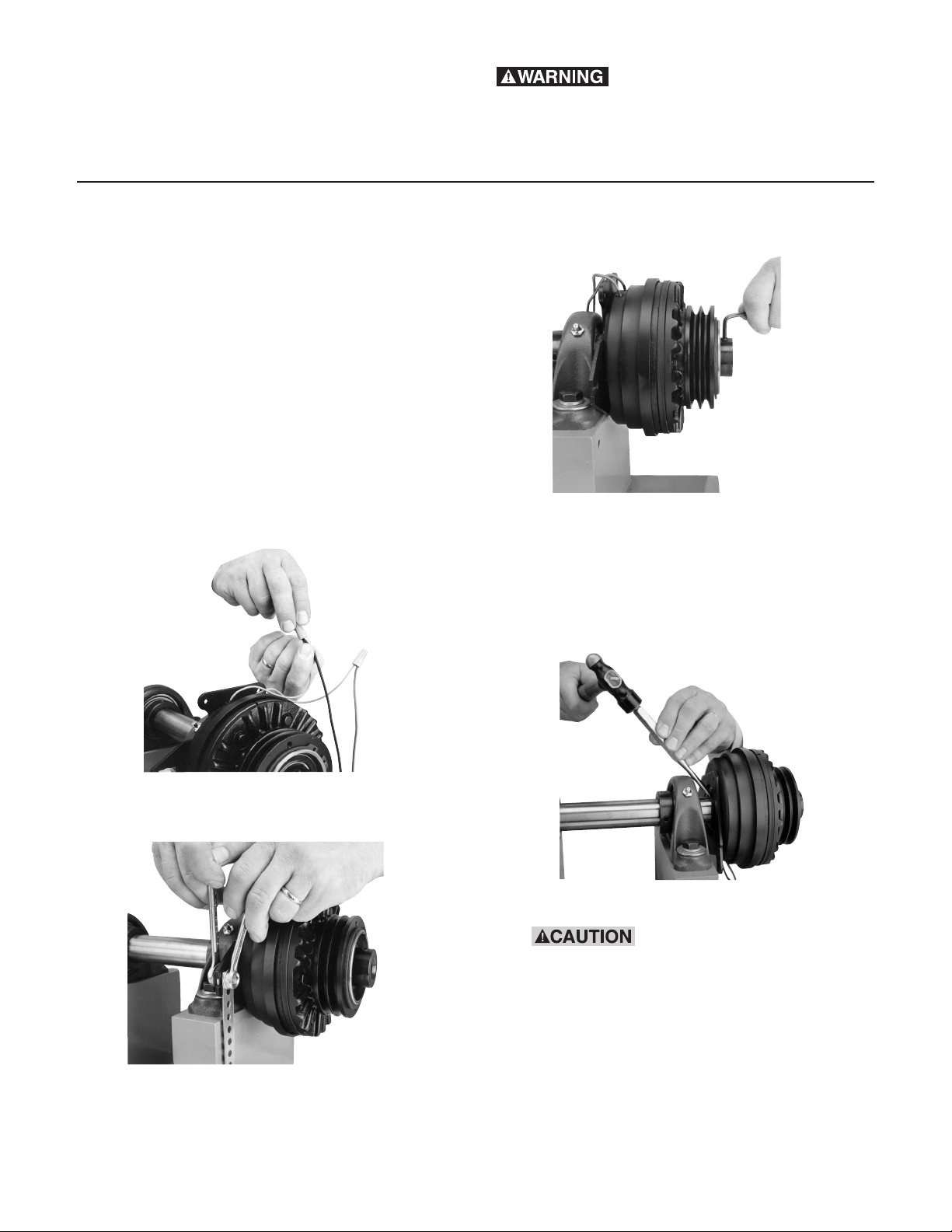
1. Turn off all power to the clutch.
2. Disconnect the coil wires from the incoming
control unit wires.
3. Disconnect the field anti-rotation pin or field
restraining arm (Item 16).
4. Loosen the setscrews (Item 6) which hold
the clutch to its shaft.
5. Remove the clutch from its shaft by pulling
and/or gently tapping the hub with a hammer and drift.
Note: Do not hit the outer portion of the
clutch outboard of the hub as this may
severely damage it.
6. Remove the retainer ring (Item 11).
When removing this or
other retaining rings, be sure to hold the
retaining ring with one hand so it will not
spring away and endanger personnel and
property should the pliers lose their grip
on the ring. Safety glasses should always
be worn when installing or removing
retaining rings.
Page 3
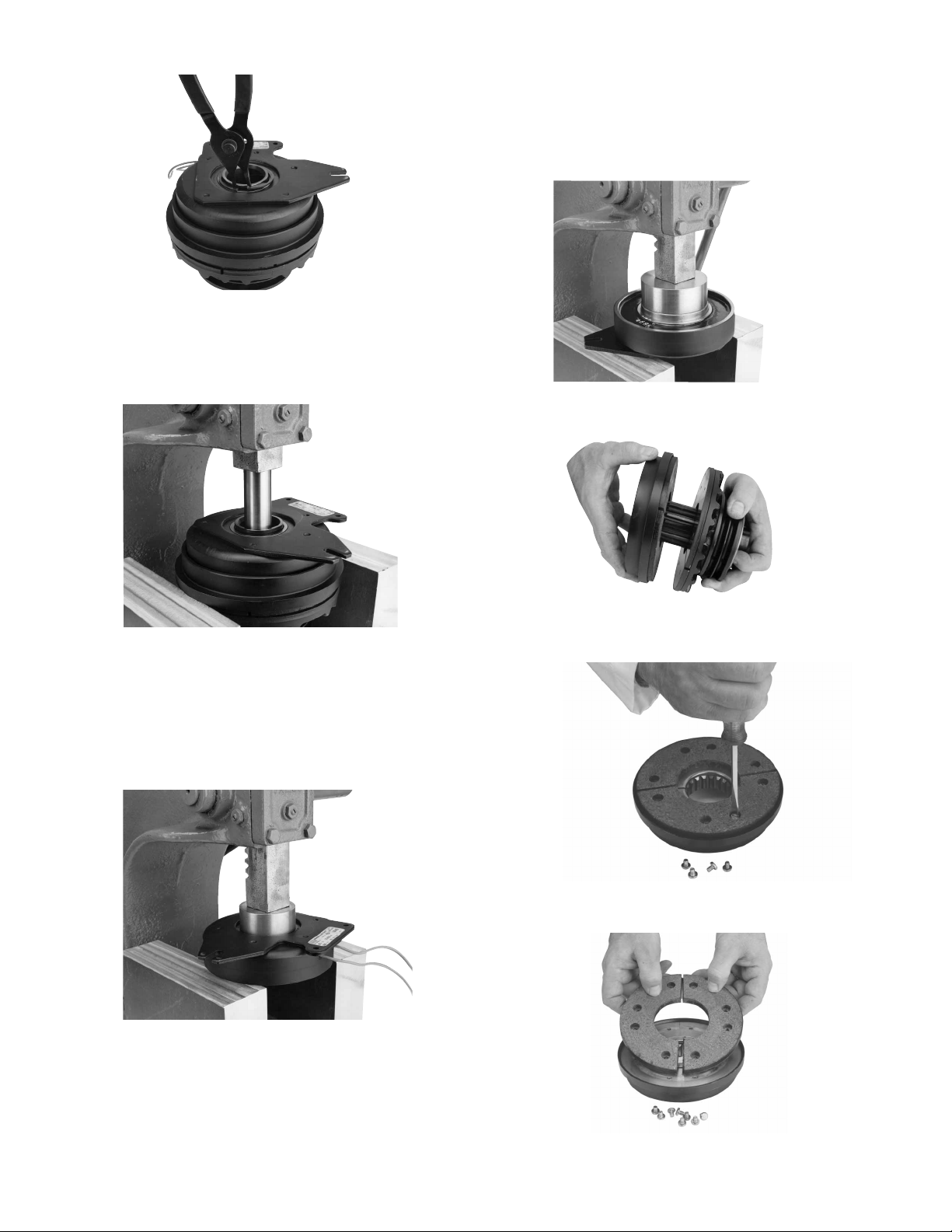
9. Press the new bearing (Item 9) into the field
assembly by pressing on the bearing outer
race. Do not press on the bearing inner
race or damage to the bearing will result,
making it unusable.
10. Remove the rotor assembly (Item 8) from
the hub (Item 6).
11. Remove the screws (item 8-5) which retain
the friction disc segments (item 8-1).
12. Lift the friction disc segments (item 8-1) off
the rotor, exposing the Autogap assembly.
7. Remove the field assembly (Item 10) and
bearing (Item 9) by locating and supporting
on the rotor outer diameter (Item 8) and
pressing on the hub (Item 6).
8. Remove the bearing (Item 9) from the field
assembly (Item 10) by pressing on the inner
race while supporting the field assembly on
its face.
Note: Use caution to avoid damaging the
epoxy covering the coil.
3
Warner Electric • 800-825-9050 819-0324
Page 4
4
Warner Electric • 800-825-9050 819-0324
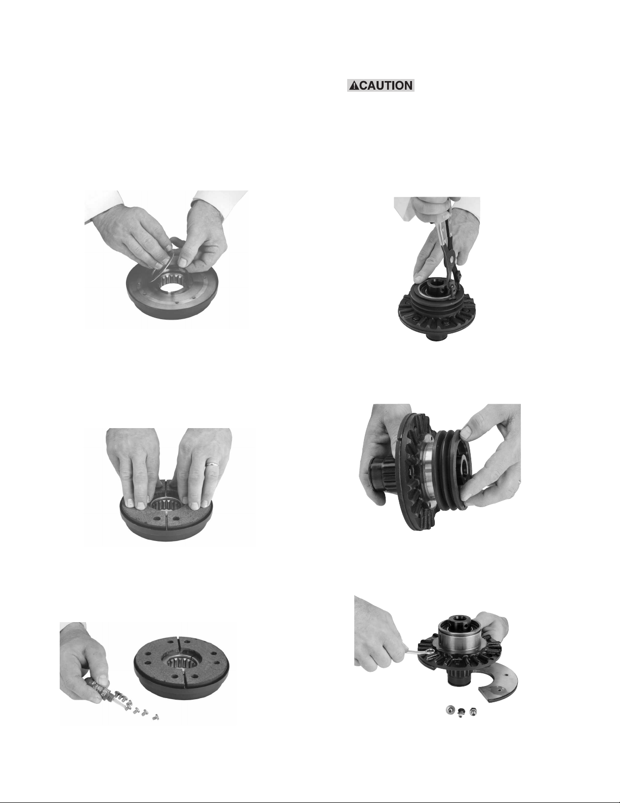
13. Install replacement Autogap components as
follows: Remove plate (item 8-2-size 115
only), and detent ring (item 8-3) to expose
wave spring (item 8-4). Remove and replace
wave spring (item 8-4). Reinstall the detent
ring and plate (items 8-3 and 8-2). Note:
The detent ring lip must point away from
the friction disc. Install the wave spring
with its split 180° from the split in the
detent ring.
14. Clean all foreign matter from rotor mounting
surface. Install the new friction disc segments (Item 8-1) with new screws (Item 8-5)
included with the kit. Note: Use only the
screws included with the kit as any others
may damage the clutch.
Apply a drop of Loctite grade AA or equivalent to each screw prior to installation.
Tighten each screw to 18-22 in. lb. torque.
15. Remove the snap ring (Item 3) from the
armature hub assembly.
When installing or removing this or other retaining rings, be sure
to hold the ring with one hand so it will
not spring away, endangering personnel
and property should the pliers lose their
grip on the ring. Safety glasses should
always be worn when installing or
removing retaining rings.
Remove the pulley, sheave, or sprocket if it
interferes with removing the cap screws
(Item 7-2).
16. Disassemble the armature hub assembly by
removing cap screws (Item 7-2), lock washers (Item 7-3) and armature segment (Item
7-1).
Page 5

5
Warner Electric • 800-825-9050 819-0324
Remove the set screws.
Remove the external and internal retaining
rings (Items 2 and 3) from the splined hub
(Item 6) and the armature hub (Item 1).
17. Locate and support on the sheave end of
the assembly near the fins and press on the
field end of the splined hub (Item 6).
To remove the hub and bearing assembly,
remove the bearings (Item 4) and spacer
(Item 5) from the hub (Item 6) by pressing
them off.
Proceed with reassembly per the following
instructions:
Note: It is imperative that all bearings be
installed exactly as instructed to avoid
damage to the bearings.
Apply one drop of Loctite grade AA or
equivalent to each cap screw thread prior to
installation.
Install the new armature segments (Item 7-
1) supplied in the kit onto the armature hub,
(Item 1) using cap screws and washers
(Items 7-2, 7-3 and 7-4).
Page 6

20. Install the spacer (Item 5) as shown in
Figure 3.
Figure 3
21. Press the outer bearing (Item 4) into place
by applying force evenly against the bearing
outer and inner races simultaneously while
supporting the armature face. Continue
pressing until the outer race firmly locates
against the spacer. See Figure 4.
Figure 4
22. Install the external and internal retaining
rings (Items 2 and 3) adjacent to the outer
bearing. (See Figure 5)
Figure 5
6
Warner Electric • 800-825-9050 819-0324
Tighten the cap screws to the appropriate
torque for your size unit:
Size Torque
25 29-35 in.-lbs.
55-115 60-84 in.-lbs.
18. Install the inner adapter bearing (Item 4)
onto the hub, (Item 6) by pressing on the
inner race of the bearing. With the end of
the hub supported as shown in Figure 1,
press the bearing until its inner race locates
against the hub shoulder.
Figure 1
19. Press the hub and bearing into the Adapter
Assembly until the outer race of the bearing
locates against the shoulder of the adapter
hub. Note that the force is to be exerted
on the outer race. Support the armature
face as shown in Figure 2.
Figure 2
Support
Support
Press
Force
Bearing
Hub
Shoulder
Hub
Press
Force
Armature
Assembly
Support
Support
Adapter
Shoulder
Press Force
Press Force
Armature
Assembly
Support
Adapter
Shoulder
Support
Spacer
Spacer
Support
Press Force
Evenly Applied
Press Force
Evenly Applied
Support
Page 7

7
Warner Electric • 800-825-9050 819-0324
Note: The Armature Assembly must rotate
freely on the hub. Inspect to insure that
the inner bearing is still firmly located
against the hub shoulder as previously
shown in (Figure 1). When inspecting,
place unit firmly on flat surface with
exposed hub end up.
Figure 1
23. Install the rotor assembly onto the hub (Item
6) making sure that the spline teeth are
aligned. When the Autogap detent ring (item
8-3) contacts the spline outside diameter,
press by hand evenly on the rotor until the
friction disc contacts the armature. Release
pressure. Support as shown. The rotor will
spring back approximately .050”. The
Autogap is now set. When the hub is rotated by hand, the armature and the friction
disc must not touch. (See Figure 6)
Figure 6
24. Press the field assembly onto the hub by
pushing the inner race of the bearing
while supporting on the hub. Apply force
until the inner race of the bearing is located
flush against the shoulder adjacent to the
spline. (See Figure 7)
Figure 7
Install the retaining ring (Item 11) on the hub
with snap ring pliers.
Rotate the hub. No interference between
the shell and rotor is allowable.
When installing or removing this or other retaining rings, be sure
to hold the ring with one hand so it will
not spring away, endangering personnel
and property, should the pliers lose their
grip on the ring. Safety glasses should
always be worn when installing or
removing retaining rings.
Support
Support
Press
Force
Bearing
Hub
Shoulder
Hub
Press
Force
SUPPORT
MAXIMUM
.050 AIRGAP
ALL AROUND
PUSH
PUSH
SPLINE
DETENT
RING
SUPPORT
SUPPORT
PRESS
FORCE
SHELL
ASSEMBLY
PRESS
FORCE
SUPPORT
UNTIL FLUSH
Page 8

8
Warner Electric • 800-825-9050 819-0324
25. Reinstall the sheave, pulley, or sprocket,
and key.
Reinstall the sheave retainer ring and conduit box, if used. Refer to the conduit box
installation instructions.
26. Reinstall the clutch assembly on the shaft,
placing the key in its keyway.
27. Tighten the hub set screws onto the key to
the appropriate torque for your size unit:
Size Torque
25 80 in.-lbs.
55 160 in.-lbs.
115 275 in.-lbs
205 275 in.-lbs.
305 670 in.-lbs.
Assure proper alignment of driving and driven sheave, pulley, or sprocket before tightening set screws.
28. Secure the field by its pin or restraining arm
accessory to avoid rotation.
29. Reconnect the wires.
30. Your AT clutch is now ready for its static
test. Apply DC voltage to the clutch coil
through the clutch control. The armature
should pull against the friction material face
with an audible “click”.
Page 9

9
Warner Electric • 800-825-9050 819-0324
31. Install the drive belt or chain.
32. Run the clutch under its operating load.
33. Your AT clutch may not achieve its full
torque until after a short “break-in” period.
To break in the clutch, cycle it on and off
under full load at operating speed a minimum of ten times in quick succession.
Your AT clutch is now ready to run.
Page 10

10
Warner Electric • 800-825-9050 819-0324
2
3
9
12
14
15
13
11
16
7-1
6
10
8-1
8
Optional
Optional
5
4
7-3
7-2
7-2
7-3
7-4
1
8-2
8-4
8-3
8-5
Page 11

Component Parts
ATC-25 ATC-55 ATC-115
Item Description Part No. Qty. Part No. Qty. Part No. Qty.
1Armature Hub 540-0907 1 540-0852 1 540-0863 1
2 Retaining Ring 748-0732 1 748-0726 1 748-0737 1
3 Retaining Ring 748-0731 1 748-0728 1 748-0736 1
4Bearing 166-0278 2 166-0277 2 166-0279 2
5 Spacer 807-0119 1 807-1061 1 807-1063 1
6 Splined Hub 1 1 1
1/2" Bore 540-0910
5/8" Bore 540-0911
3/4" Bore 540-0912 540-1501
7/8" Bore 540-0913 540-1502
1" Bore 540-1503
1-1/8" Bore 540-1504 540-0857
1-1/4" Bore 540-0858
1-3/8" Bore 540-0859
1-1/2" Bore 540-0860
*7-1 Armature 110-0220 1 110-0218 1 110-0223 1
*7-2 Screw 797-1519 4 797-1462 6 797-1463 6
*7-3 Lockwasher 950-0436 4 950-0355 6 950-0355 6
*7-4 Flatwasher 950-0023 2 950-0023 2
*8 Rotor 5161-751-001 1 5162-751-001 1 5163-751-001 1
8-1 Facing Assembly 5161-445-003 1 5162-445-003 1 5163-445-003 1
8-2 Retainer Plate 686-0108 1
8-3 Detent Ring 748-2031 1 748-2038 1 748-2020 1
8-4 Wave Spring 808-0404 1 808-0401 1 808-0384 2
8-5 Machine Screw 797-1389 8 797-1389 8 797-1389 8
*9 Bearing 166-0283 1 166-0284 1 166-0279 1
10 Field Assembly 1 1 1
6 volts DC 5161-451-002 5162-451-002 5163-451-002
90 volts DC 5161-451-003 5162-451-003 5163-451-003
24 volts DC 5161-451-004 5162-451-004 5163-451-004
*11 Retainer Ring 748-0018 1 748-0727 1 748-0737 1
12 Adapter 104-0300 2
13 Screw 797-1396 4
14 Lockwasher 950-0102 4
Optional Accessory Items
15 Conduit box 100-1 5162-101-002 1 5162-101-002 1 5162-101-002 1
16 Restraining Arm Assembly 5162-101-004 1 5162-101-004 1 5163-101-004 1
Kit Items
* Clutch Rebuild Kit 5161-101-011 1 5162-101-011 1 5163-101-011 1
(includes items 7-1, 7-2, 7-3, 7-4, 8, 9, 11)
Note: In some versions of this product, item 8 consists of a one (1) piece rotor.
Friction Face Replacement Kit 5161-101-007 5162-101-007 5163-101-007
For Clutches with Replaceable Friction Face Only
Mounting Accessory Kits (not shown)
1 1/2” Bore - 3/4” Bore 5161-101-001
1-1 Ring Retainer Ext. 748-0734 1
1-2 Wire Retainer 742-0027 1
1-3 Key 590-0104 1
1-4 Setscrew 797-1393 2
1 7/8’ Bore 5161-101-002
1-1 Ring Retainer Ext. 748-0734 1
1-2 Wire Retainer 742-0027 1
1-3 Key 590-0104 1
1-4 Collar and Setscrew 266-0031 1
1 3/4’ Bore - 1” Bore 5162-101-001
1-1 Ring Retainer Ext. 748-0725 1
1-2 Wire Retainer 742-0026 1
1-3 Key 590-0103 1
1-4 Setscrew 797-1386 2
1 1-1/8’ Bore 5162-101-010
1-1 Ring Retainer Ext. 748-0725 1
1-2 Wire Retainer 742-0026 1
1-3 Key 590-0103 1
1-4 Setscrew 797-1077 2
1-5 Collar 266-0032 1
1 All bore sizes 5163-101-001
1-1 Ring Retainer Ext. 748-0738 1
1-2 Wire Retainer 742-0026 1
1-3 Key 590-0105 1
1-4 Setscrew 797-1395
11
Warner Electric • 800-825-9050 819-0324
Page 12

Warranty
Warner Electric LLC warrants that it will repair or replace (whichever it deems advisable) any
product manufactured and sold by it which proves to be defective in material or workmanship
within a period of one (1) year from the date of original purchase for consumer, commercial or
industrial use.
This warranty extends only to the original purchaser and is not transferable or assignable without
Warner Electric LLC’s prior consent.
Warranty service can be obtained in the U.S.A. by returning any defective product, transportation
charges prepaid, to the appropriate Warner Electric LLC factory. Additional warranty information
may be obtained by writing the Customer Satisfaction Department, Warner Electric LLC, 449
Gardner Street, South Beloit, Illinois 61080, or by calling 815-389-3771.
A purchase receipt or other proof of original purchase will be required before warranty service is
rendered. If found defective under the terms of this warranty, repair or replacement will be made,
without charge, together with a refund for transportation costs. If found not to be defective, you
will be notied and, with your consent, the item will be repaired or replaced and returned to you
at your expense.
This warranty covers normal use and does not cover damage or defect which results from
alteration, accident, neglect, or improper installation, operation, or maintenance.
Some states do not allow limitation on how long an implied warranty lasts, so the above limitation
may not apply to you.
Warner Electric LLC’s obligation under this warranty is limited to the
repair or replacement of the
defective product and in no event shall Warner Electric LLC be liable for consequential, indirect,
or incidental damages of any kind incurred by reason of the manufacture, sale or use of any
defective product. Warner Electric LLC neither assumes nor authorizes any other person to give
any other warranty or to assume any other obligation or liability on its behalf.
WITH RESPECT TO CONSUMER USE OF THE PRODUCT, ANY IMPLIED WARRANTIES WHICH
THE CONSUMER MAY HAVE ARE LIMITED IN DURATION TO ONE YEAR FROM THE DATE OF
ORIGINAL CONSUMER PURCHASE. WITH RESPECT TO COMMERCIAL AND INDUSTRIAL
USES OF THE PRODUCT, THE FOREGOING WARRANTY IS IN LIEU OF AND EXCLUDES ALL
OTHER WARRANTIES, WHETHER EXPRESSED OR IMPLIED BY OPERATION OF LAW OR
OTHERWISE, INCLUDING, BUT NOT LIMITED TO, ANY IMPLIED WARRANTIES OF
MERCHANTABILITY OR FITNESS.
Some states do not allow the exclusion or limitation of incidental or consequential damages, so
the above limitation or exclusion may not apply to you. This warranty gives you specic legal
rights and you may also have other rights which vary from state to state.
Changes in Dimensions and Specifications
All dimensions and specications shown in Warner Electric catalogs are subject to change without
notice. Weights do not include weight of boxing for shipment. Certied prints will be furnished
without charge on request to Warner Electric.
Warner Electric LLC
31 Industrial Park Road • New Hartford, CT 06057
815-389-3771 • Fax: 815-389-2582
www.warnerelectric.com
P-1404 819-0324 6/05 Printed in USA
 Loading...