

Page 1
AT Brake–Major Service Repair
Instructions for Sizes 25, 55, 115
P-1405
819-0325
Repair Instructions
Page 2
Contents
Instructions . . . . . . . . . . . . . . . . . . . . . . . . . . . . 2
Warranty . . . . . . . . . . . . . . . . . . . . . . Back Page
Failure to follow these
instructions may result in product
damage, equipment damage, and
serious or fatal injury to personnel.
A major rebuild of an AT brake can be
accomplished by following these instructions to
replace the parts furnished in the appropriate
Warner Electric brake rebuild kit. Proceed
as follows:
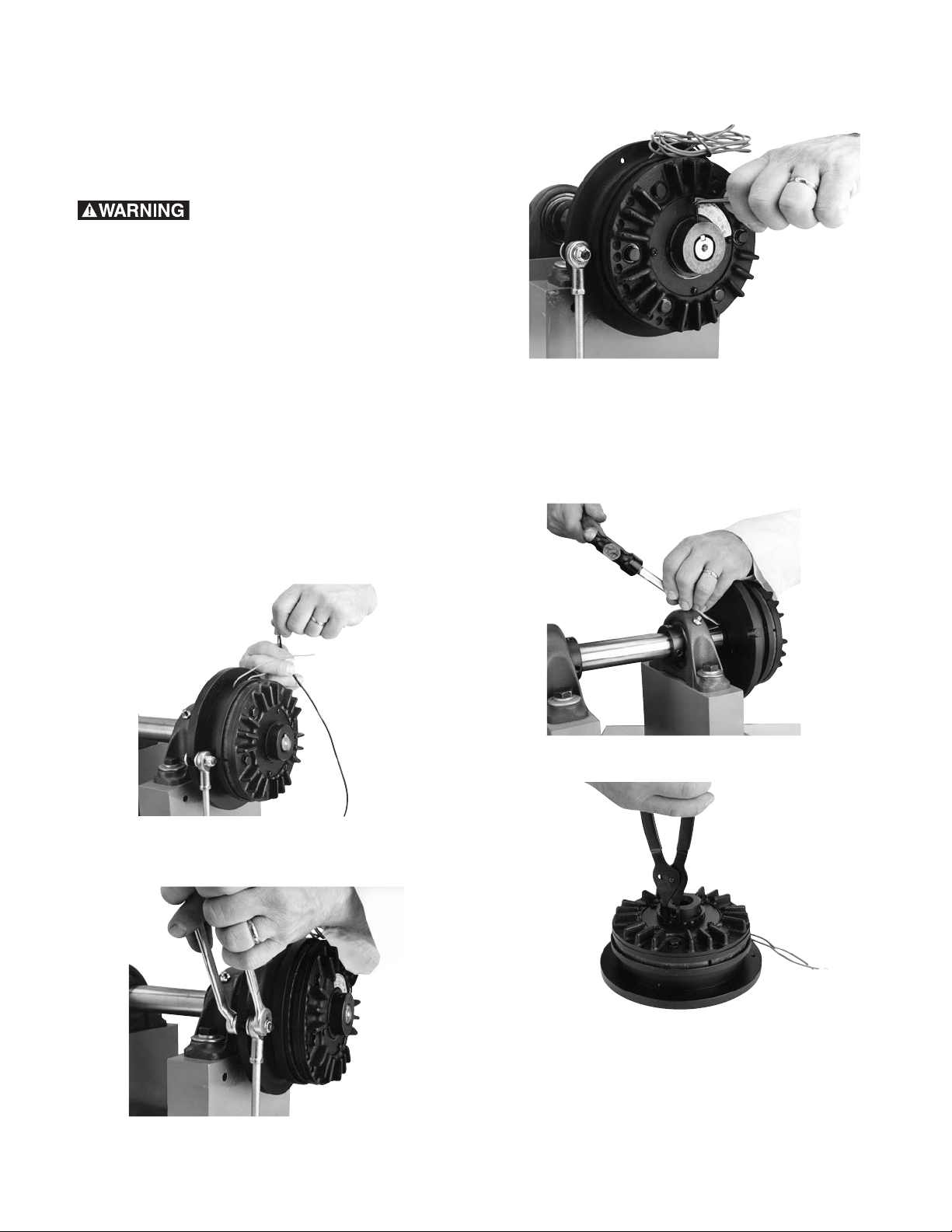
1. Turn off all power to machine and brake using
appropriate electrical lockout procedures.
2. Disconnect the brake coil wires from the
incoming control unit wires, and remove
optional conduit box from brake if used.
4. Loosen the hub set screws holding brake on
shaft.
5. Remove the brake from its shaft by pulling
and/or gently tapping the hub with a hammer
and drift. Note: Do not hit the outer portion
of the brake outboard of the hub as this may
severely damage it.
6. Remove retaining ring.
3. Disconnect the anti-rotation torque arm from
the magnet.
Warner Electric • 800-825-9050 P-1405 • 819-0325
2
Page 3
When installing or removing
this or other retaining rings, be sure to
hold the ring with one hand so it will not
spring away, endangering personnel and
property, should the pliers lose their grip
on the ring. Safety glasses should always
be worn when installing or removing
retaining rings.
Remove plate retaining screws and plate.
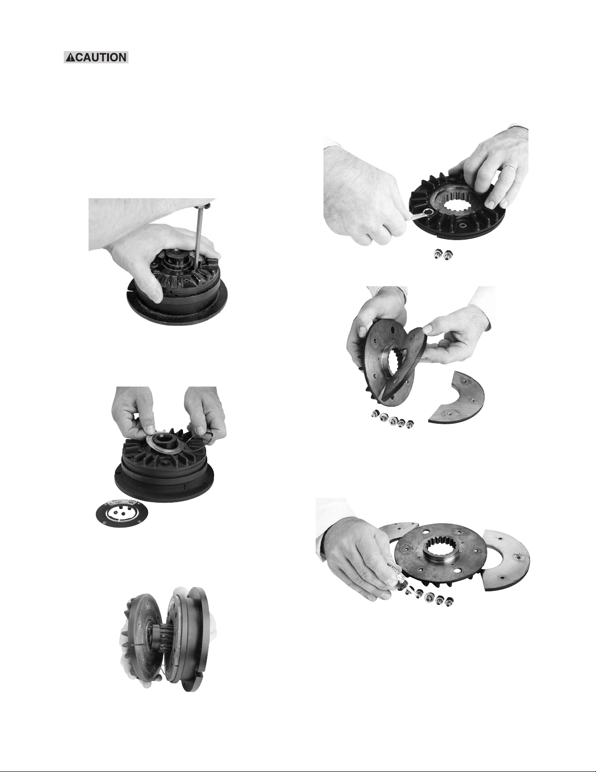
7. Remove the armature retaining screws and
washers.
Remove the armature segments.
Remove wave spring and detent ring from
armature hub.
Lift the armature hub away from magnet
assembly.
8. Clean the removed hardware and apply one
®
drop of Loctite
grade AA or equivalent to each
capscrew thread before installation.
Warner Electric • 800-825-9050 P-1405 • 819-0325
3
Page 4

Install new armature segments onto the
Plate
Wave Spring
Detent Ring
Armature Hub
Wave Spring
Spring ends
placed up
Detent Ring
Slot in Detent
180º apart from
slot in Wave Spring
armature hub and fasten with capscrews and
washers.
Tighten the capscrews to the appropriate
torque specifications for your size unit:
Size Torque
25 29-35 in.-lbs.
55, 115 60-84 in.-lbs.
9. Install detent ring. The raised lip is to face the
hub armature fins.
Install the wave spring plate and screws.
Note: Install the wave spring with its split
180° from the split in the detent ring.
Warner Electric • 800-825-9050 P-1405 • 819-0325
4
Page 5

10. Remove the friction material segment
retaining screws and lift out the friction
material segments.
Press the hub with its bearing, out of the
magnet assembly. BE CAREFUL TO
AVOID DAMAGING THE EPOXY WHICH
COVERS THE COIL.
12. Remove the bearing from the hub by
pressing it off.
11. Turn the magnet assembly over and remove
screws.
Remove backplate and shim.
Remove retaining ring to expose the bearing.
13. Press the new bearing into the magnet
assembly. Be careful to press only the
outer race of the bearing.
Warner Electric • 800-825-9050 P-1405 • 819-0325
5
Page 6

14. Install shim and backplate.
Press
Hub
Magnet
Assembly
Support
Clean the removed hardware and apply one
drop of Loctite grade AA or equivalent to each
screw thread before threading into holes.
Tighten the screws to the appropriate torque
for your size unit:
15. Install the hub into the bearing by supporting
on the inner race of the bearing and pressing on the outer end of the hub. Press until the
inner race of the bearing is flush with the
shoulder on the hub. (See Figure 1)
Install the retaining ring on the hub adjacent to
Size Torque
the bearing.
25 16-20 in.lbs.
55, 115 30-35 in.lbs.
16. Clean all foreign material from the magnet
mounting surface. Install new friction
material segments from the kit.
Figure 1
Warner Electric • 800-825-9050 P-1405 • 819-0325
6
Page 7

The recessed holes should be facing away
Press Evenly
Approximately
1/16 Airgap
All Ground
Support
Support
Armature
Assembly
from the magnet body.
Clean the supplied hardware and apply one
drop of Loctite grade AA or equivalent should
be applied to each thread before installation.
Do not allow Loctite to get on friction material
surface.
17. Place the brake mounting flange down and
place the armature assembly on the hub. First
engage the spine teeth, then uniformly apply
force by hand, pushing the detent ring over
the spline outside diameter. Now apply force
to the Armature Assembly until the armature
contacts the friction disc. (See Figures 2 and
2A)
Rotate the hub and armature assembly by
hand. There should be no interference.
Install the retaining ring on the hub adjacent to
the armature.
Fasten with new screws. Note: Use only the
screws furnished with the kit as others may
damage the brake.
Tighten each screw to 18-22 in.lbs. of torque.
Figure 2
When installing or removing
this or other retaining rings, be sure to
hold the ring with one hand so it will not
spring away, endangering personnel and
property, should the pliers lose their grip
on the ring. Safety glasses should always
be worn when installing or removing
retaining rings.
18. Reinstall the brake on the shaft with the key in
its keyway.
Figure 2A
Warner Electric • 800-825-9050 P-1405 • 819-0325
7
Page 8

19. Tighten the hub set screws, on the shaft and
key per the following torque specifications:
Size Torque
25 80 in.lbs.
55 160 in.lbs.
115 275 in.lbs.
21. Reconnect the wires.
22. Your AT brake is now ready for its static test.
Apply DC voltage to the coil through the brake
control. The armature should pull against the
friction material face with an audible click.
20. Secure the torque arm to the brake. The
torque arm attachment must be flexible
enough to compensate normal shaft and
bearing runout without causing binding or side
loading to the brake.
23. Run the brake under its operating load.
24. Your AT brake might not achieve its full torque
until after a short “break-in” period. To break in
the brake, cycle it on and off under full load at
operating speed a minimum of ten times in
quick succession. (See note)
Your AT brake is now ready to run.
Note: Your application may require more
cycles to achieve full torque due to load and
RPM.
Warner Electric • 800-825-9050 P-1405 • 819-0325
8
Page 9

Warranty
Warner Electric LLC warrants that it will repair or replace (whichever it deems advisable) any
product manufactured and sold by it which proves to be defective in material or workmanship within a
period of one (1) year from the date of original purchase for consumer, commercial or industrial use.
This warranty extends only to the original purchaser and is not transferable or assignable without Warner
Electric LLC’s prior consent.
Warranty service can be obtained in the U.S.A. by returning any defective product, transportation charges
prepaid, to the appropriate Warner Electric LLC factory. Additional warranty information may be obtained by
writing the Customer Satisfaction Department, Warner Electric LLC, 449 Gardner Street, South Beloit, Illinois
61080, or by calling 815-389-3771.
A purchase receipt or other proof of original purchase will be required before warranty service is
rendered. If found defective under the terms of this warranty, repair or replacement will be made, without
charge, together with a refund for transportation costs. If found not to be defective, you will be notified and,
with your consent, the item will be repaired or replaced and returned to you at your expense.
This warranty covers normal use and does not cover damage or defect which results from
alteration, accident, neglect, or improper installation, operation, or maintenance.
Some states do not allow limitation on how long an implied warranty lasts, so the above limitation may not
apply to you.
Warner Electric LLC’s obligation under this warranty is limited to the repair or replacement of the
defective product and in no event shall Warner Electric LLC be liable for consequential, indirect,
or incidental damages of any kind incurred by reason of the manufacture, sale or use of any defective
product. Warner Electric LLC neither assumes nor authorizes any other person to give any other warranty or
to assume any other obligation or liability on its behalf.
WITH RESPECT TO CONSUMER USE OF THE PRODUCT, ANY IMPLIED WARRANTIES WHICH THE
CONSUMER MAY HAVE ARE LIMITED IN DURATION TO ONE YEAR FROM THE DATE OF ORIGINAL
CONSUMER PURCHASE. WITH RESPECT TO COMMERCIAL AND INDUSTRIAL USES OF THE
PRODUCT, THE FOREGOING WARRANTY IS IN LIEU OF AND EXCLUDES ALL OTHER WARRANTIES,
WHETHER EXPRESSED OR IMPLIED BY OPERATION OF LAW OR OTHERWISE, INCLUDING, BUT NOT
LIMITED TO, ANY IMPLIED WARRANTIES OF
MERCHANTABILITY OR FITNESS.
Some states do not allow the exclusion or limitation of incidental or consequential damages, so the above
limitation or exclusion may not apply to you. This warranty gives you specific legal rights and you may also
have other rights which vary from state to state.
Changes in Dimensions and Specifications
All dimensions and specifications shown in Warner Electric catalogs are subject to change without notice.
Weights do not include weight of boxing for shipment. Certified prints will be furnished without charge on request to Warner Electric.
Warner Electric
31 Industrial Park Road • New Hartford, CT 06057
815-389-3771 • Fax: 815-389-2582
www.warnerelectric.com
P-1405 • 819-0325 8/11 Printed in USA
 Loading...