

Page 1
~ 1 ~
Installation and operation manual DC
Page 2

~ 2 ~
Installation and operation manual DC
1. Warning
First and foremost, check the condition of your heat pump as soon as you receive it,
write any reservations you have about its state on the delivery note if you have any
doubts or a problem and send a registered letter to your installer or directly to the
manufacturer within 48 hours. After this period, no claim will be accepted.
1.1 Important information
To properly install your heat pump, read this manual carefully. We will not be liable
for any injury to persons or damage to the machine due to any errors that might occur
during installation.
- The installation of this heat pump must be carried out by qualified personnel,
- This heat pump meets the manufacturing and communication standards defined
by FPP's DTP10 and NFPAC,
- The maintenance of this heat pump must be carried out as set out in this manual,
- Only use original spare parts supplied by the manufacturer,
- Failure to follow these instructions or the information in this manual will void the
heat pump's guarantee.
2. Your heat pump
2.1 Main features
Your heat pump must not be used for any purpose other than to HEAT your pool. Its
choice was determined following a personalized heat budget and it cannot be used for
other pools until a new heat budget has been carried out.
Your heat pump is one of the most efficient and environmentally friendly heaters,
using R32 gas.
Page 3
~ 3 ~
Installation and operation manual DC
* Test carried out at an air temperature of 27°C, with the same temperature difference and water
as at 15°C.
** Test carried out at an air temperature of 15°C, with an inlet water temperature of 26°C and an
outlet water temperature of 28°C to define the water flow, heating capacity and power
consumption, according to FPP standards.
*** Test carried out at an air temperature of 35°C, with an inlet water temperature of 30°C and
an outlet water temperature of 29°C.
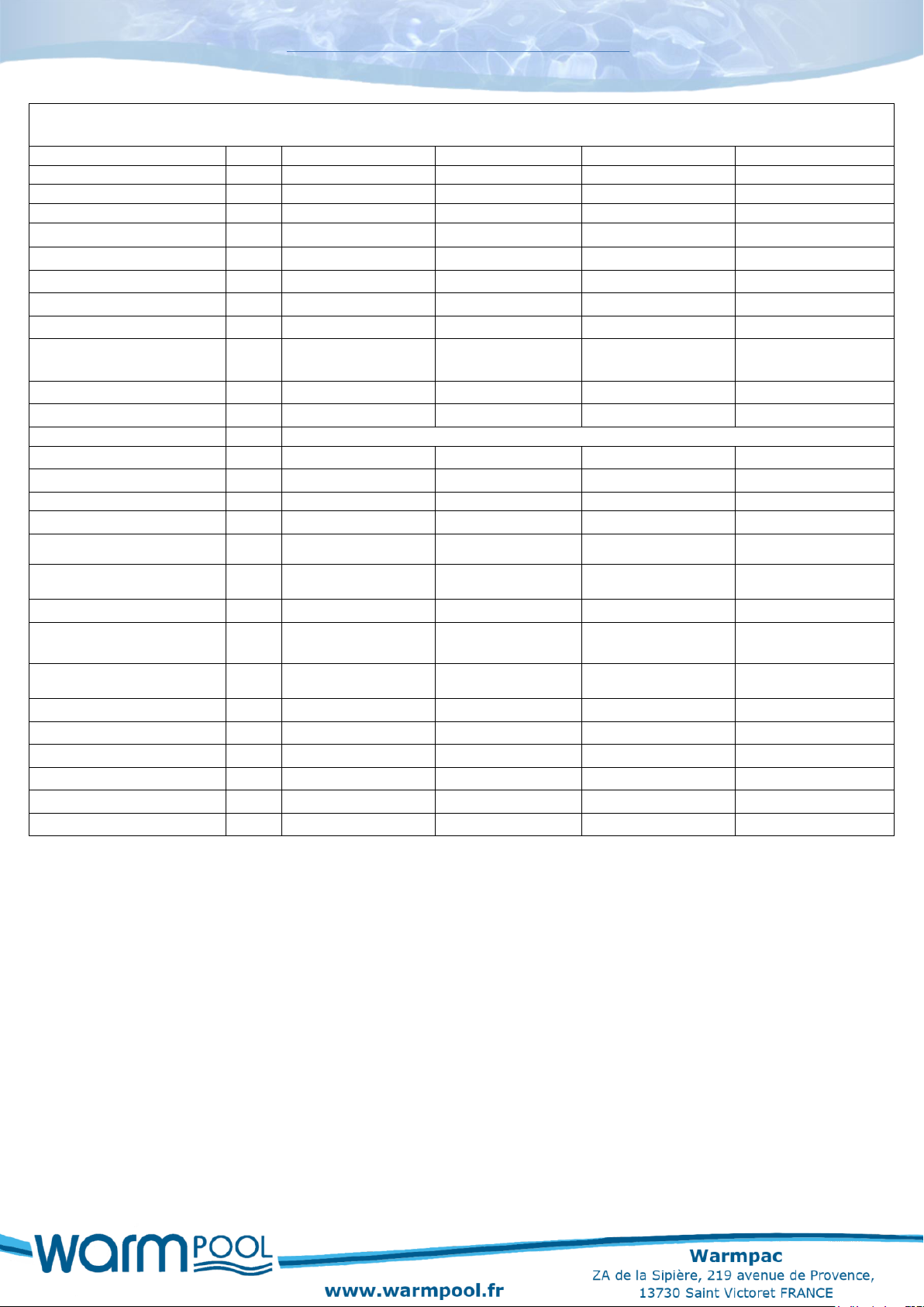
2.2 Technical characteristics
MODELE DC55
DC75
DC95
DC115
Pool size
Maxi
55m³
75m³
95m³
115m³
Heating capacity *
kW
1.3~ 7.93
1.75~ 10.90
3.21~15.81
3.21~ 17.05
Power consumption *
kW
0.12~ 1.37
0.16~ 1.96
0.31~ 3.03
0.32~ 3.98
COP * 11.24~5.79
10.88~ 5.56
10.3~5.22
10.01~4.82
Rated current
A
0.9~6.0
1.2~8.6
1.5~13.3
2.0~17.5
Heating capacity **
kW
0.96 ~ 6.46
1.52~ 8.21
2.3~ 12.14
2.07~ 15.20
Power consumption **
kW
0.19~ 1.32
0.25~ 1.84
0.37~ 2.80
0.38~ 3.60
Cooling capacity ***
kW
3.72
4.3
6.2
7.69
Cooling power
consumption ***
kW
1.45
1.78
3.3
2.66
EER *** 2.57
2.43
1.86
2.89
Casing material
ASA
ASA
ASA
ASA
Controller
Touch LCD display
Gas
R32
R32
R32
R32
Heat exchanger
Titanium twist
Titanium twist
Titanium twist
Titanium twist
Compressor
Rotary Mitsubishi
Rotary Mitsubishi
Rotary Mitsubishi
Rotary Mitsubishi
Number of fans
1 1 1
1
Fan rotation speed (PRM)
T/mn
400-750
400-800
300-750
400-750
Mode
Cooling / Heating /
Auto
Cooling / Heating /
Auto
Cooling / Heating /
Auto
Cooling / Heating /
Auto
Operating range
-5℃~43℃
-5℃~43℃
-5℃~43℃
-5℃~43℃
Noise level at 1 m
dB(A)
41~50
42~51
42~55
45~56
Power supply
Mono 220-
240V/50HZ
Mono 220-
240V/50HZ
Mono 220-
240V/50HZ
Mono 220-
240V/50HZ
Throttling EEV
EEV
EEV
EEV
Water volume
m3/H
2.7
3.5
5.2
5.6
Unit dimension
mm
1000/418/605
1000/418/605
1046/453/767
1160/490/862
Carton dimension (l/L/h)
mm
1030/435/615
1030/435/615
1130/480/780
1210/510/880
Net weight / Gross weight
kg
47/58
51/62
66/79
74/88
All parts guarantee
3 ans
3 ans
3 ans
3 ans
Page 4
~ 4 ~
Installation and operation manual DC
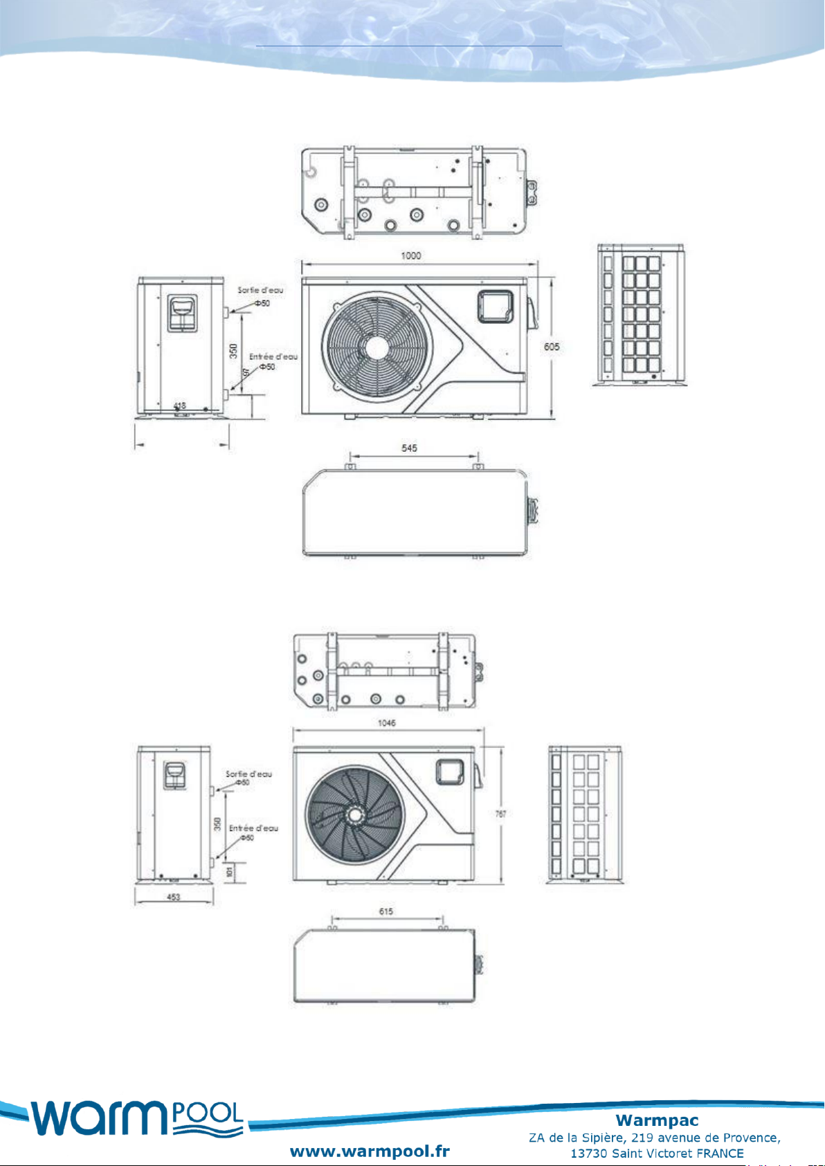
2.3 Dimension of swimming pool heat pump DC 55/75
2.4 Dimension of swimming pool heat pump DC 95
Page 5
~ 5 ~
Installation and operation manual DC
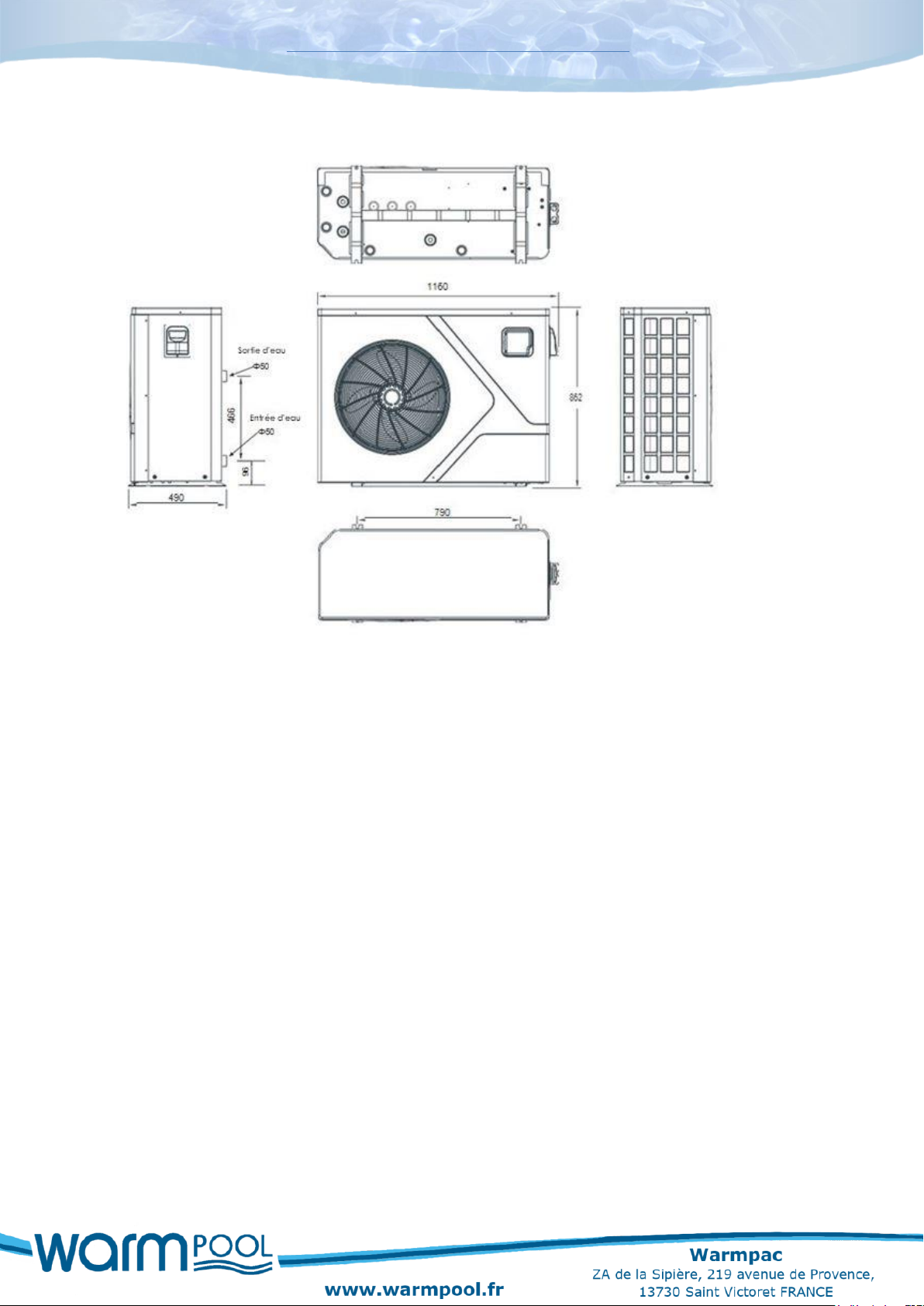
2.5 Dimension of swimming pool heat pump DC 115
3. Installation and connections
3.1 Installation
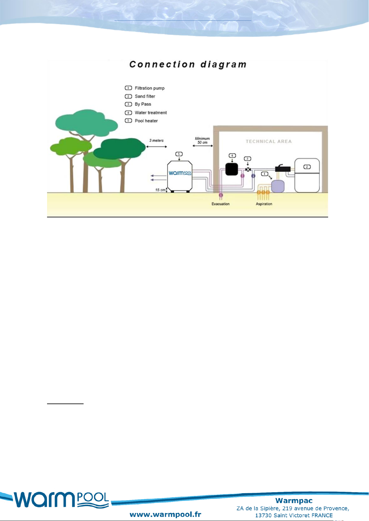
Your heat pump and your pool pump must be installed close to each other.
Your heat pump must be placed outdoors and must follow the minimum spacings shown on the connection diagram.
Your heat pump should be level and at least 15 cm above the ground. We recommend you use blocks and drain the condensation into a sump (which can be covered with gravel).
If any of these recommendations are not followed or are not applicable, please contact the manufacturer to make sure that the installation performed or to be performed will not affect the proper functioning of your heat pump.
Using your heat pump will necessarily create condensation (up to several liters of water per hour). This is not a leak.
Page 6
~ 6 ~
Installation and operation manual DC
3.2 Hydraulic connection
Before carrying out any work, remember it is vital that all the valves are closed.
As you can see from the connection diagram, you need to install a BYPASS valve (if you do not already have one) between the filtration system and the water treatment system (or discharge).
Upstream of this BYPASS, an OUT pipe with a shut-off valve will be connected to the water inlet of the heat pump and a RETURN pipe with a shut-off valve will be connected to the water outlet of the heat pump.
Use the PVC connectors provided in the accessory kit to connect the hoses to the heat pump. On the pump side, fasten the supplied fittings using Teflon tape to ensure a good seal.
Important: Before filling the pump with water, we recommend washing/rinsing the filter.
Page 7
~ 7 ~
Installation and operation manual DC
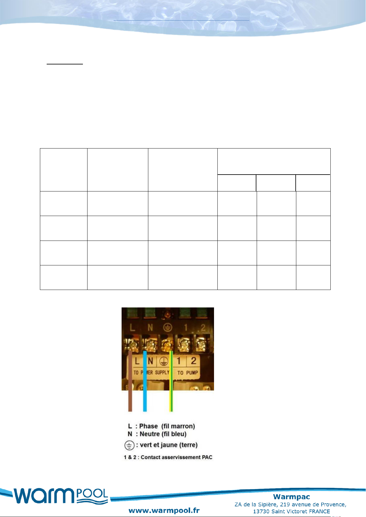
3.3 Electrical connection
Important: The electrical connection of your heat pump must be carried out by someone qualified to do it. Check that the cable supplying the machine room is rated for the additional current required by the pump.
The heat pump must be powered from a separate D-curve circuit breaker which may be
either on the main electrical panel fitted with a differential circuit breaker or on an
independent panel connected to the main switchboard, with a differential circuit
breaker. If this is not the case add a differential circuit breaker to the heat pump's
independent panel.
Model
Supply
Circuit breaker rater
D-curve
Cable cross-section as a function of
the distance between the circuit-
breaker and the heat pump
< 10m 10 to 15m > 15m
DC 55
Single phase 230V
16 Amps
3G2.5
mm2
3G2.5
mm2
3G6
mm2
DC 75
Single phase 230V
20 Amps
3G2.5
mm2
3G2.5
mm2
3G6
mm2
DC 95
Single phase 230V
25 Amps
3G2.5
mm2
3G2.5
mm2
3G6
mm2
DC 115
Single phase 230V
25 Amps
3G2.5
mm2
3G2.5
mm2
3G6
mm2
Unscrew the knob to access the electrical connection.
Page 8
~ 8 ~
Installation and operation manual DC
4. Start-up
a) Checking the valves
The BYPASS valve must be fully open.
The inlet and outlet water valves must be closed.
b) Clean the filter
c) Valve settings
Open your valves following the order and setting recommended below, and check for water leaks.
- Set the BYPASS valve to half open,
- Fully open the water inlet valve of the heat pump,
- Set the water outlet valve of the heat pump to 1/3.
At the end of these adjustments, check your sand filter pressure gauge, the pressure should not increase beyond 0.2 bar (the pressure should stay in the green zone).
Press the ON/OFF button to start the heat pump.
Important: Leave the machine running for at least 10 minutes before changing the
initial valve settings to get a difference between the inlet and outlet water
temperatures of between 1°C and 3°C
Remember to clean your filter every week to ensure the proper operation of not only the filter but also the heat pump.
Page 9
~ 9 ~
Installation and operation manual DC
5. Using the heat pump
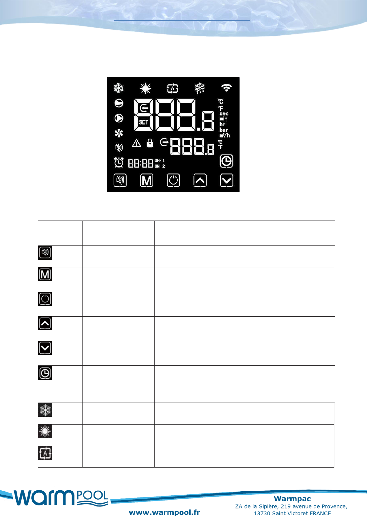
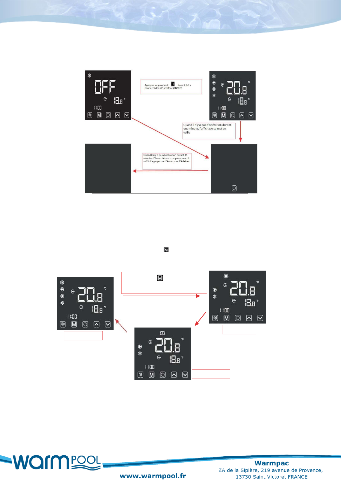
5.1 Interface screen
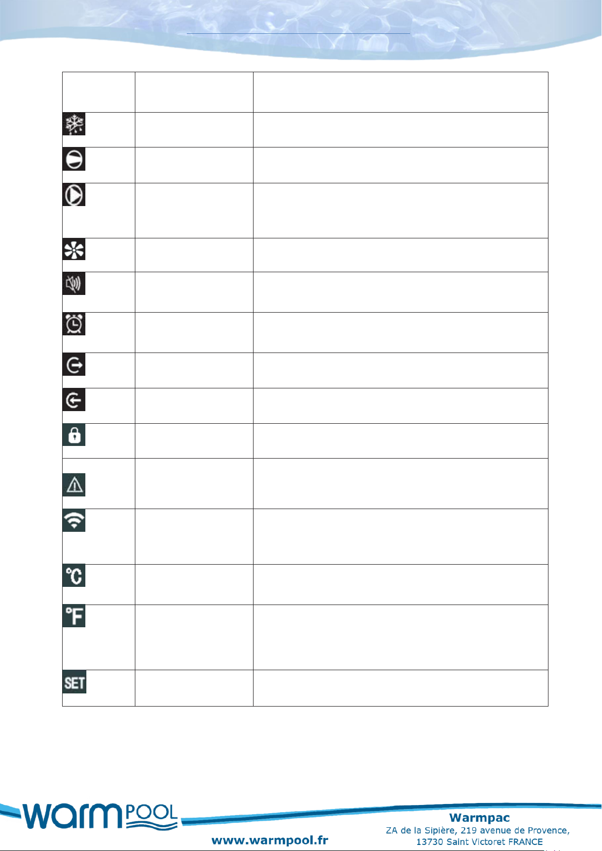
5.2 Instructions and functions of the icon keys
Main
symbols
Name
Function
Silent mode
Silent mode available only on our Inverter models.
Mode switch
Changes the operating mode and the access to parameter
settings.
On-Off switch
Start and stop button, cancels an operation in progress and
returns to the previous operating level.
Up switch
Used to scroll through the parameters and operating and
temperature values.
Down switch
Used to scroll through the parameters and operating and
temperature values.
Clock switch
The clock allows the user to set the time. It is important to
set the time so that the operating programs saved in
synchronisation remain active.
Cooling symbol
Displayed when cooling the water.
Heating symbol
Displayed when heating the water.
Automatic symbol
Displayed in automatic mode.
Page 10
~ 10 ~
Installation and operation manual DC
Main
symbols
Name
Function
Defrost symbol
Displayed when the unit is in the defrosting process.
Compressor symbol
Displayed when the compressor is running.
Water pump symbol
Displayed when the heat pump detects water flowing
through the heat pump and that the water circulation pump
is operating correctly.
Fan symbol
Displayed when the fan is running.
Silent mode
Displayed only when this mode is active or programming
is active. Available only in our Inverter ranges.
Schedule
Programming
Displayed when a time schedule is being recorded.
Water outlet symbol
Displays the water outlet temperature.
Water inlet symbol
Displays the water inlet temperature.
Lock symbol
Displayed when the keypad is locked.
Error symbol
In the event of a failure of the unit, an error code will be
displayed on the screen.
Wireless signal
symbol
When the device is connected to the WIFI module, this icon
appears on the display and the number of bars depends on
the WIFI signal strength.
Degrees Celsius
Symbol
Displays temperatures in degrees Celsius.
Degrees Fahrenheit
Symbol
Displays temperatures in degrees Fahrenheit.
To change the temperature display, go to the operating
parameters
Setting symbol
Used to set a parameter.
Page 11
~ 11 ~
Installation and operation manual DC
5.3 Sarting up your heat pump
Change of mode
Sous In the main interface, briefly press" "to toggle the unit between heating, cooling
and automatic modes.
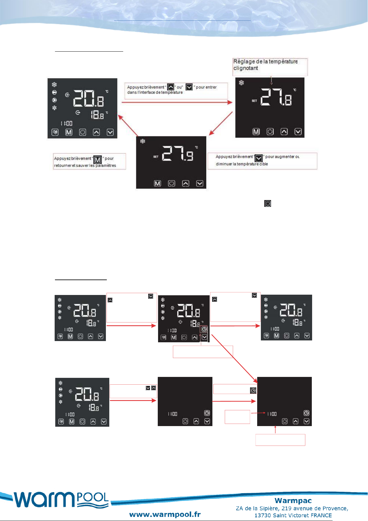
Mode chauffage
Mode refroidissement
Mode automatique
Appuyez brièvement pour passer d’un
mode
à l’autre, si pas d’ opération durant 2 s, le mode actuel
sera sauvé
Page 12
~ 12 ~
Installation and operation manual DC
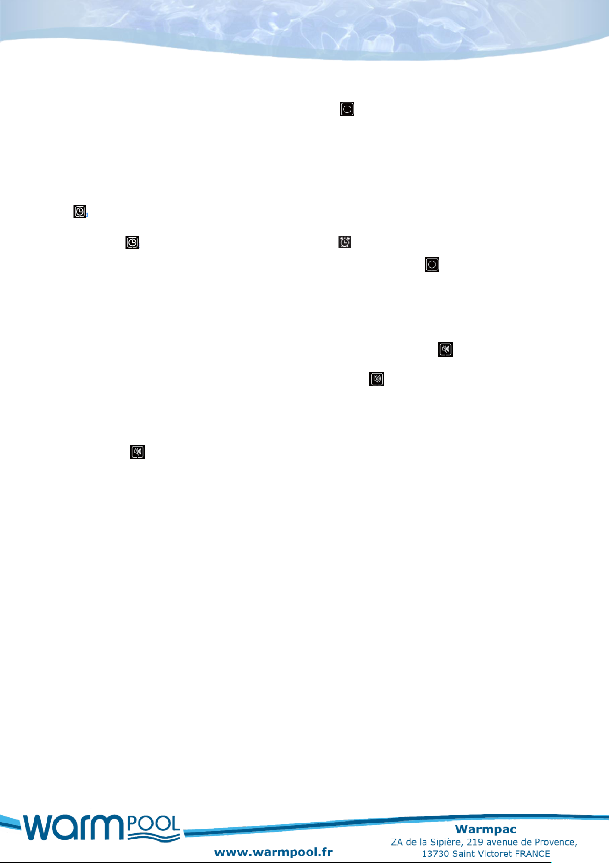
Temperature settings
Comments: In the temperature setting interface, if you briefly press , the system will
return to the main display and no changes will be saved. When the temperature appears
on the display after you set the value you want, wait 5 seconds and the temperature
displayed will be saved as the set temperature. The system will automatically store the
user setting and return to the main interface.
Setting the clock
Appuyez longuement sur
durant 2 s.
Appuyez d’une impulsion
Pour avoir accès au réglage de
l’heure.
Maintien l’écran horloge en
permanence
Appuyez brièvement
pour régler l’heure
Appuyez sur pour sauvegarder
Chiffres heure
clignote
Interface de réglage de
l’heure système
Page 13
~ 13 ~
Installation and operation manual DC
Locking the controller
To lock or unlock the wireless controller press the symbol for 5 seconds.
Schedule programming
To get to this function press the up and down arrows for 2 seconds at the same time, the
symbol will be displayed.
Press the symbol for 3 seconds to display the symbol. To set your schedule, use
the up and down arrows. To check your programme and exit press .
Silence mode
When silent mode is active, it appears on the screen with this symbol .
To program an operating schedule, press and hold 2 sec .
Then press the up and down arrows to set a PAC start time on "ON" and off on "OFF".
To stop the silence option, go to the "OFF" time setting using the UP and DOWN keys,
then press . This icon will disappear.
Page 14
~ 14 ~
Installation and operation manual DC
5.4 Error code
When the unit detects a failure, an error code is shown on the controller. The following
table gives the description of the error and the action to take.
ERROR CODE
DESCRIPTION
E01
The HP pressure switch has detected an abnormality in the refrigerant
regulation. The sensor signals an excessive refrigerant pressure during heat
pump operation.
Contact the after-sales service.
E02
The LP pressure switch has detected an abnormality in the refrigerant
regulation. The sensor signals a low refrigerant pressure during heat pump
operation.
Contact the after-sales service.
E03
Faulty contact in the flow sensor.
Solution:
-Check the calibration of the water inlet and outlet valves and the water
pressure in your system must be greater than 0.9 bar
-Make sure the flow sensor wires are connected to the electronic board, to
test it, disconnect the wires and then reconnect them.
-Close the hydraulic valves, remove the flow switch, clean the inside of the
flow switch if it is dirty or has any limescale in it
Apply pressure to the detector vane to trigger the contact manually and
simulate the flow of water, if the error code disappears after one minute of
maintained pressure, it means the flow sensor is working, otherwise, if the
error code remains set, replace the flow sensor
E04
The LP&HP pressure switches have detected an abnormality in the
refrigerant regulation. The sensors are malfunctioning due to not enough
refrigerant in the heat pump.
Contact the after-sales service.
E08
The connection between the control box and the heat pump is not working.
Solution:
-Make sure the control wires are connected to the electronic board in place:
"12V brown wire - NET blue wire - GND green & yellow wire"
-Check the connection of the remote command wire connection
If this does not resolve the fault, replace the control box
P01
Fault in the water inlet temperature sensor.
Solution:
-Check the calibration of the water inlet and outlet valves
-Make sure the sensor wires are connected to the electronic board
-Check that the sensor is correctly installed on the hydraulic heat exchanger
-Check the condition of the sensor, make sure that the cable is not damaged
or cut
after the checks, if the error code remains set, replace the sensor
P02
Fault in the water outlet temperature sensor.
Solution:
-Check the calibration of the water inlet and outlet valves
-Make sure the sensor wires are connected to the electronic board
-Check that the sensor is correctly installed on the hydraulic heat exchanger
-Check the condition of the sensor, make sure that the cable is not damaged
or cut
after the checks, if the error code remains set, replace the sensor
Page 15
~ 15 ~
Installation and operation manual DC
P03/P04
Fault in the ambient air temperature sensor.
Solution:
-Make sure the wires are properly connected to the electronic board
-Check that the sensor is correctly fitted on the machine's rear grill
-Check the condition of the sensor, make sure that the cable is not damaged
or cut
after the checks, if the error code remains set, replace the sensor
P05
Fault in the refrigerant evaporation temperature sensor in the copper lug at
the bottom of the evaporator.
Solution:
-Make sure the wires are properly connected to the electronic board
-Check that the probe is well installed on the terminal at the bottom of the
evaporator
-Check the condition of the sensor, make sure that the cable is not damaged
or cut
after the checks, if the error code remains set, replace the sensor
P06
Significant temperature difference between the water inlet and the water
outlet or fault in the electronic board PCB
Solution:
-Check the setting of your water inlet and outlet valves
-Check the water inlet and outlet sensors
(see error codes P01/P02)
-Water flow rate too low or flow switch is stuck in the closed position. (see
error code E03)
After the checks, if the error code remains set, replace electronic board PCB
P07
Fault in the air intake temperature sensor.
Solution:
-Make sure the wires are connected to the electronic board
-Check the condition of the sensor, make sure that the cable is not damaged
or cut
-After the checks, if the error code remains set, replace the temperature
sensor
-If there is no sensor in this location and the error code remains set, install a
6.8 kΩ resistor
If you encounter a fault with an F code, please contact our technical service.
Page 16

~ 16 ~
Installation and operation manual DC
6. Maintenance and guarantee
Maintenance is mainly about keeping your machine in good condition so that it does not give you any problems.
6.1 Maintenance to be done
Clean the evaporator: Use a water jet, making sure to keep the jet in the direction of the fins, from top to bottom. The evaporator aluminium fins should be cleaned regularly to ensure a good airflow.
Regularly clear the condensate outlets to prevent the accumulation of water within the
chassis. Otherwise, the fan blades may be attacked and damaged by the acidity of the
water. This will not affect the correct operation of your machine, but we recommend
that you clean the evaporator to stop the process.
6.2 Wintering
Winterisation is mandatory at the end of the period of use to prevent any damage.
- Shut off power to the machine at the circuit breaker,
- Open the By-Pass valve, close the inlet and outlet water valves,
- Unscrew the inlet and outlet connections of your heat pump,
- Purge your hydraulic system,
- Leave about 5 cm between the connections and the machine during the winter
season.
6.3 On-site servicing
As part of the guarantee, the manufacturer may carry out an on-site service or request the return of the heat pump. Only the manufacturer may make the decision to carry out an on-site service.
This operation may be covered under the guarantee, depending on the invoice date and the type of fault.
Page 17

~ 17 ~
Installation and operation manual DC
Outside the guarantee period, or in the event of a failure not covered by the guarantee, the manufacturer may offer an on-site service. The customer must accept a quote in advance.
No after-sales service interventions will change the guarantee period.
6.4 DC manufacturer’s guarantee
The manufacturer's guarantee is for 3 years. As well as this parts guarantee, labour
costs are included only if the equipment is returned to our workshops. If the heat pump
has to be returned, the transport costs are the responsibility of the customer for the
transport to our workshops, and of the manufacturer for the return transport costs.
The guarantee may not be honored if:
Your heat pump has not been installed using best practice, following the recommendations described in this manual.
Routine maintenance has not been carried out, especially the cleaning of the evaporator and the condensate outlets. There should not be any standing water within the chassis.
The damage is due to improper installation, bad connections, or an incorrect placement of the installation.
The damage or repairs are the result of misuse, abuse, improper repairs, unauthorized modifications or third-party equipment faults.
The damage is due to flooding, wind, fire, lightning, accidents, corrosive atmospheres or other conditions beyond your dealer's control.
Parts have been replaced by parts that are not supplied or approved by your dealer.
The damage is to persons or property of any kind whatsoever, including any direct, indirect, special or consequential damage resulting from the use or loss of use of the product.
Page 18

~ 18 ~
Installation and operation manual DC
Limitation :
This guarantee is exclusive and replaces all other implied warranties of merchantability
or fitness for a particular purpose and any other explicit or implied guarantees. The
indemnifications provided for in this guarantee are exclusive and are Warmpac's only
obligation, any other claim made by any person will have no effect.
6.5 Safety advice
- Do not touch the fan when it is running, it could hurt you,
- Keep children well clear of the equipment,
- Regularly check the power supply and connection cables of your heat pump. If you
have any doubt, contact your installer,
- For after-sales service, you must use the original manufacturer parts.
 Loading...