

Wanjiaan Interconnected Technology HE722WS User Manual
1
WIFI KIT
WIFI IPC Operation Manual
1.WIFI IPC Installation
Please make sure the device is intact and all the parts are ready before installation.
Note: The mounting wall should withstand at least 4 times the total weight of the wifi camera and
accessories.
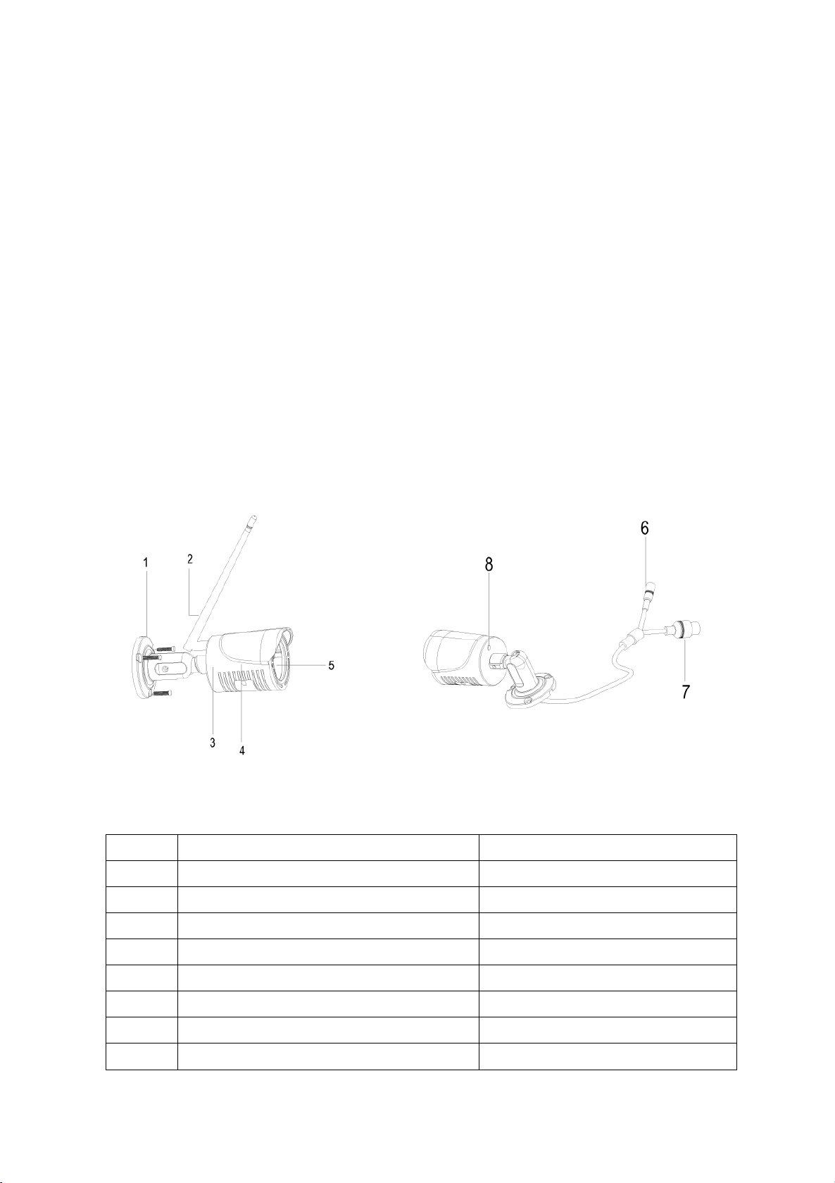
1.1 WIFI IPC appearance and interface
Interface for the wifi camera, refer to following figure 1-1
Figure 1-1 wifi camera appearance indication and interface diagram
No.
Name
Function
1
3-axis bracket
Adjust direction of the camera
2
Antenna
Transmitting & receiving wifi signal
3
Rear cover
Rear cover for housing
4
Front cover
Front cover for housing
5
Double ring glass
Prevent light leaking from lens
6
Power port
DC12V power supply
7
matching button
NVR matching
8
antenna port
Antenna port base
2
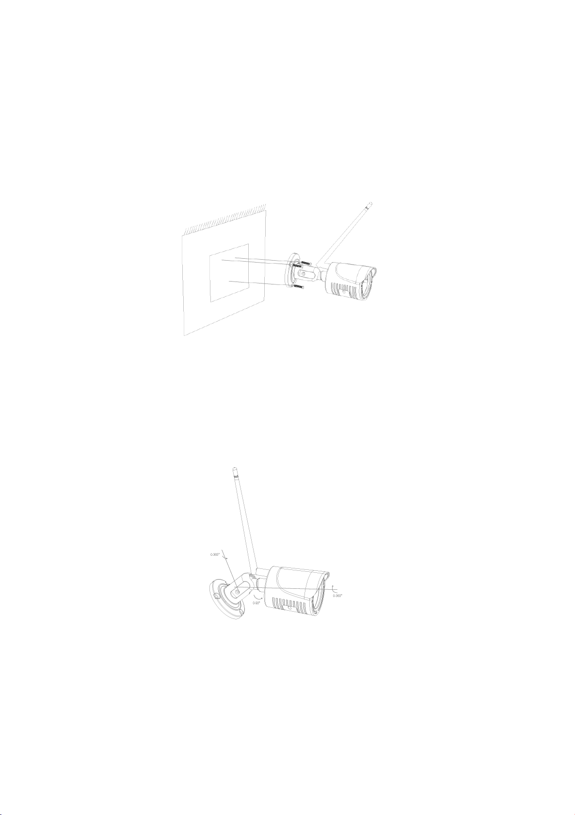
1.2 Installation procedure
1. Drilling mounting hole: Mark the hole position in the mounting wall, drilling 3 holes by a Φ5mm drill, the
depth of the hole is not less than 30mm, and then insert the wall plugs to the hole.
2. Fixing the wifi camera: using the PA4 screw to fix the camera base to the mounting wall. As show in figure
2-2 .
Figure 2-2 fixing the wifi camera
3. Adjust the 3-axis bracket: loosen the locking screw for the bracket and then adjust the bracket. By adjusting
the shaft connection between bracket and the base to realize the direction adjustment. Horizontal (P) 0-360
degree, vertical (T) 0-90 degree, and rotating(R) 0-360 degree. Tightening the screw when it reach the
appropriate scene. As show in figure 2-3.
Figure 2-3 3-axis bracket adjustment
 Loading...