

Page 1
WANHAO Duplicator i3
User Manual V1.2
© Wanhao USA 2015
www.wanhaousa.com
Page 2

Safety
WARNING: The components on the Duplicator i3 generate high temperatures and move
extremely fast. Reaching inside of the Duplicator i3 while it is in operation may cause injury.
Stay clear of the printer frame perimeter while the machine is in operation. Always control the
Duplicator i3 from the rotary dial on the front of the printer or via the computer software. Never
push or pull any of the components by hand. After a print, make sure your printer is off and that
your nozzle is no longer hot before removing a model from the printer.
WARNING: The Duplicator i3 is a heavy machine and extra caution is advised when
lifting/moving the printer. Failure to properly lift/move the printer can result in injury.
CAUTION:
turned
result in electrical shock.
CAUTION:
When
and the power cord is disconnected from the wall socket. Failure to do so can
off
Only use the stock power supply provided with your Duplicator i3.
opening the Duplicator i3 for service, ensure that the power supply is
Page 3
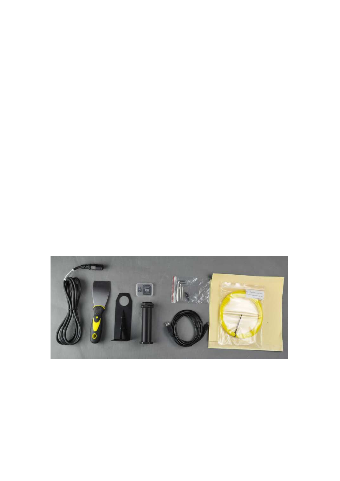
What's In The Box
Duplicator i3 3D Printer
Control Box
Model Removal Tool
Hex Screws & Key Kit
Filament Spool Holder
Spool Holder Stand
10M (~30FT) PLA Filament Pack
USB Cable
SD Card Kit
Platform Tape Sheets
Power Supply Cable
Page 4

Unboxing &
Hardware Setup #1
Your printer was packed securely to ensure safe shipment and storage. Make sure
to remove shipping ribbons, foam inserts, and packaging carefully to
damage. Make sure to begin the unboxing by laying the outer printer box on a dry,
clean, and stable work surface (table or floor).
prevent
1. Cut off shipping ribbons & open
the outer printer box.
3. Remove the top-layer foam insert.
2. Remove the cardboard
accessories box.
4. You should now see your printer
base and control box
NOTE: Never lift your printer by any electronics cables! We also recommend that you
keep your printer box for future transport and long-term storage.
Page 5
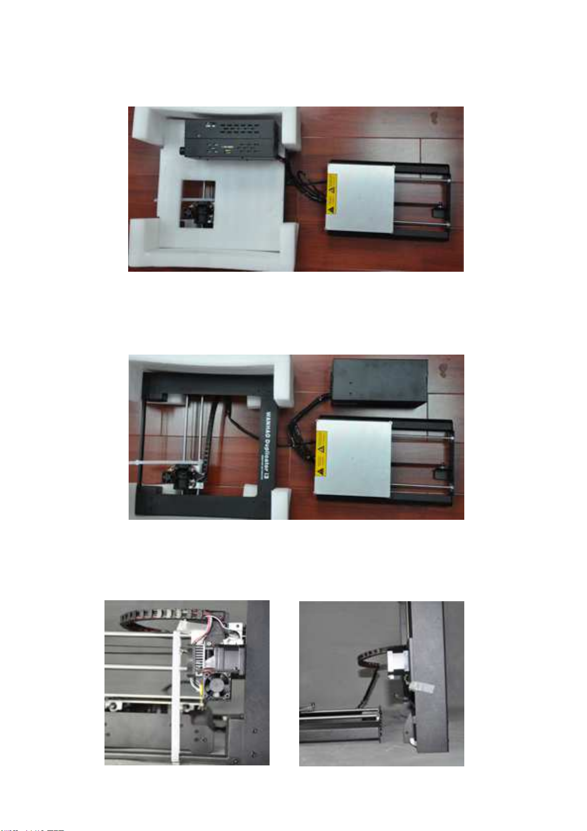
5. Remove the printer base from the foam packaging and place onto a
flat surface.
6. Remove and place the control box next to the printer base. Remove
the second-layer foam insert revealing the square tower frame & the
extruder assembly.
7. Cut the white ribbon that secures
the extruder assembly to the tower
frame.
8. Remove the tower frame and stand
it up vertically on the flat surface.
Page 6

9. Insert the printer base into the tower frame and match the screw
slots where the two frames meet.
10. Locate the screws (4 PCS) in your cardboard accessories
box
and use them to screw the tower frame to the printer base. Start
by screwing in one screw from the outside of the frame towards the
inside of the frame.
11. Lastly, turn your printer on it's side and insert a screw from
the inside of the frame towards the outside of the frame. This will lock
in your frames and prevent shifting of during operation.
Page 7

Once your tower is locked in placed you will need to make sure that your X-Axis (the
2 parallel rods running left-to-right) is perfectly level to your printing platform. You
can raise each side of the X-Axis by turning the couplers at the bottom of the Z-Axis
threaded rods.
12. Raise/lower the right side of
the X-Axis by turning the
cylindrical coupler at the bottom
of the
Z-Axis threaded rod.
13. Do the same for the coupler
on the left side. You need to
make sure that your X-Axis (the 2
parallel rods running left-to-right)
is perfectly level.
Page 8

Hardware Setup #2
Find the Spool Holder Stand
position on top of the Control Box by aligning the two screw slots so
that they are at the rear of the stand. Insert 2 screws and secure the
stand to the Control Box.
and the Control Box. Place the stand into
Find
the Filament Spool Holder and unscrew 1 of the end nuts on the
side with 2 end nuts. Place the holder through the hole in the stand and
secure the previously removed end nut back into place.
Page 9

Hardware Setup #3
To protect your printer against damage during shipping we have disconnected the
Z-Axis and X-Axis stepper motor cable connectors. You will need to insert each
connector into their corresponding sockets before using your printer. The longest
cable is for X-Axis.
The other 2 cables near the sides of your printer are for the Z-Axis stepper motors.
To insert the connector simply line up the terminals and give a slight push.
Right side Z-Axis stepper
motor.
Left side Z-Axis stepper
motor.
Page 10

Hardware Setup #4
Find your build platform (it’s the aluminum plate towards the front of
your printer on which you will be building your models). Tear off one
masking
possible. You will be printing on this sheet. You can also use painter's tape as a
substitute.
tape sheet and cover the platform with the sheet being as smooth as
Note: Your printer is able to operate
using 2 voltage options: 110V and
220V. Make sure you set the switch to
the correct voltage
country's power supply voltage (USA
uses 110V). Before connecting
anything, make sure that the
Duplicator i3 power switch is in the
OFF position.
Find your Power Cable in the
cardboard accessories box and plug
it into the power supply socket on
your Control Box (the socket is
located next to the power switch).
according to your
Your Hardware Setup is now
complete.
Page 11

Powering On Your Printer
Once you have prepared your printer
for operation press the power switch
on the back of your control box. The
power switch is located next to the
power cable socket.
If you are not able to turn your printer
on please re-check all of your power
cable connections.
Upon turning on your printer you should see the WANHAO logo while your printer's
firmware boots up and then ultimately the status monitor screen. While your printer is
in operation the status monitor screen will show you real-time information pertinent to
your printer.
Use the rotary dial on the front of your
control box to browse through the LCD
menu.
When you wish to make a selection on
the LCD menu push-click the rotary dial.
Page 12

Leveling Your Build Platform
Properly leveling your build platform is crucial to the quality of your print. The term
"leveling your build platform" refers to the manipulation of the four corners of your
build platform in order to properly space the distance in between your extruder
nozzle and the build surface...this is what will ultimately determine the resolution,
strength, and accuracy or your prints. The image below will show you the correct
and incorrect height at which your nozzle should be in relation to the build
platform:
SIDE VIEW END VIEW COMMENTS
Nozzle Too High:
Insufficient contact
area resulting in
poor adhesion and
extrusion skipping.
OK:
Filament pushed
into the build
surface slightly to
maximize surface
area contact while
still allowing good
extrusion flow.
Nozzle Too Low:
Not enough
clearance for the
filament to be
extruded...this will
result in damage to
the extruder and/or
build surface.
Page 13

Before you start leveling the build plate
make sure that you have placed your
build surface (Tape Sheet, Glass Plate,
or Custom Surface) onto your build
plate so that you can account for the
added height of your chosen surface
during leveling.
To begin leveling your build plate push-click the rotary dial so that you are within
the LCD's Main Menu. Scroll down to QUICK SETTINGS and push-click the
rotary dial once more.
Next, scroll down to HOME ALL and your stepper motors will begin to operate in
sequence to leave your nozzle resting right above the left-front of your build
surface.
The image to the right shows where
your
after selecting HOME ALL.
extruder assembly should rest
At this point go ahead and turn your
printer OFF via the power switch on the
back of your control box.
Page 14

Once you have turned your printer OFF
there will no longer be power to your
stepper motors and you will be able to
move the platform (Forward/Back along
the Y-Axis) and also the extruder
assembly (Left/Right along the X-Axis).
This will allow you to MANUALLY move
the platform & extruder assembly so
that you can check nozzle heights at all
four corners of the build platform.
Because your prints will normally start at the very center of your build plate you
should check your nozzle height about 2 in. (50mm) from each corner towards
the center. The image below shows blue X's at the recommended spot to check
your nozzle height. Checking your nozzle height at these X's will allow a more
accurate leveling for smaller prints that would normally not extend far out into
the corner of your build plate.
Page 15

Manually move your platform & extruder
assembly to nozzle height check
position #1 and take a look at the space
between the brass nozzle tip
underneath the extruder assembly and
the build surface. Turn the wingnut
underneath the closest corner of the
build platform either clockwise or
counter-clockwise to raise or lower that
particular corner.
By raising the corner height you are bringing that part of the platform closer to
the nozzle.
By lowering the corner height you are moving that part of the platform further
away form the nozzle.
The space between the brass nozzle tip
and the build surface should be roughly
the thickness of 1 sheet of copy paper.
To be accurate, slide a sheet of copy
paper back and forth between the two
components and keep adjusting the
height until you can barely feel the
nozzle dragging down the movement of
the copy paper.
You will do this for ALL four corners. If you want to be totally accurate you can
also do this same nozzle height check procedure for the very center of the
build plate.
*Note that once you adjust the height for one of the positions then your other
previously adjusted positions may become affected and need re-adjustment.
Although tedious, the best prints are always started by having a perfectly
leveled build platform.
Your build platform leveling is now complete.
 Loading...