

Walton WF-HP-226 Owner's Manual
Sample specifications for WF-HP-226
Cold water centrifugal atomizing type humidifier and mounting
brackets for installation
in
duct systems negative or positive
pressure. Maximum allowed positive static pressure -
.25" H
2
0.
Water reservoir includes float valve to automatically regulate
water level. Humidifier includes motor, impeller, disk and
breaker comb to produce a fine vapor. Rotating parts
shall be
electronically balanced to eliminate vibration. Tubes shall
be
employed to direct moisture into vertical or horizontal duct
systems and
equalize humidifier internal air pressure to that
of
the duct. All water exposed parts to be copper, brass, or nonferrous alloy. Vapor output
of
the humidifier shall
be
constant
while
in
operation and shall not depend
on
the temperature
of
the air or water. Humidifier(s) shall
be
Model WF-HP-226 as
manufactured by Humidity source. Must
be
UL listed for US and
Canada.
-
SPECIFICATIONS
CAPACITY
Moisture Output - 3 Ib'/hr.
WEIGHT
Net: 17
lb.
Shipping: 19
lb.
Operating: 20
lb.
WATER CONNECTIONS & PRESSURES
Supply: 1/8" Male
Pipe Thread
Overflow:
%"
Female Pipe Thread
Operating Pressure Range: 1
0-1
00 psig
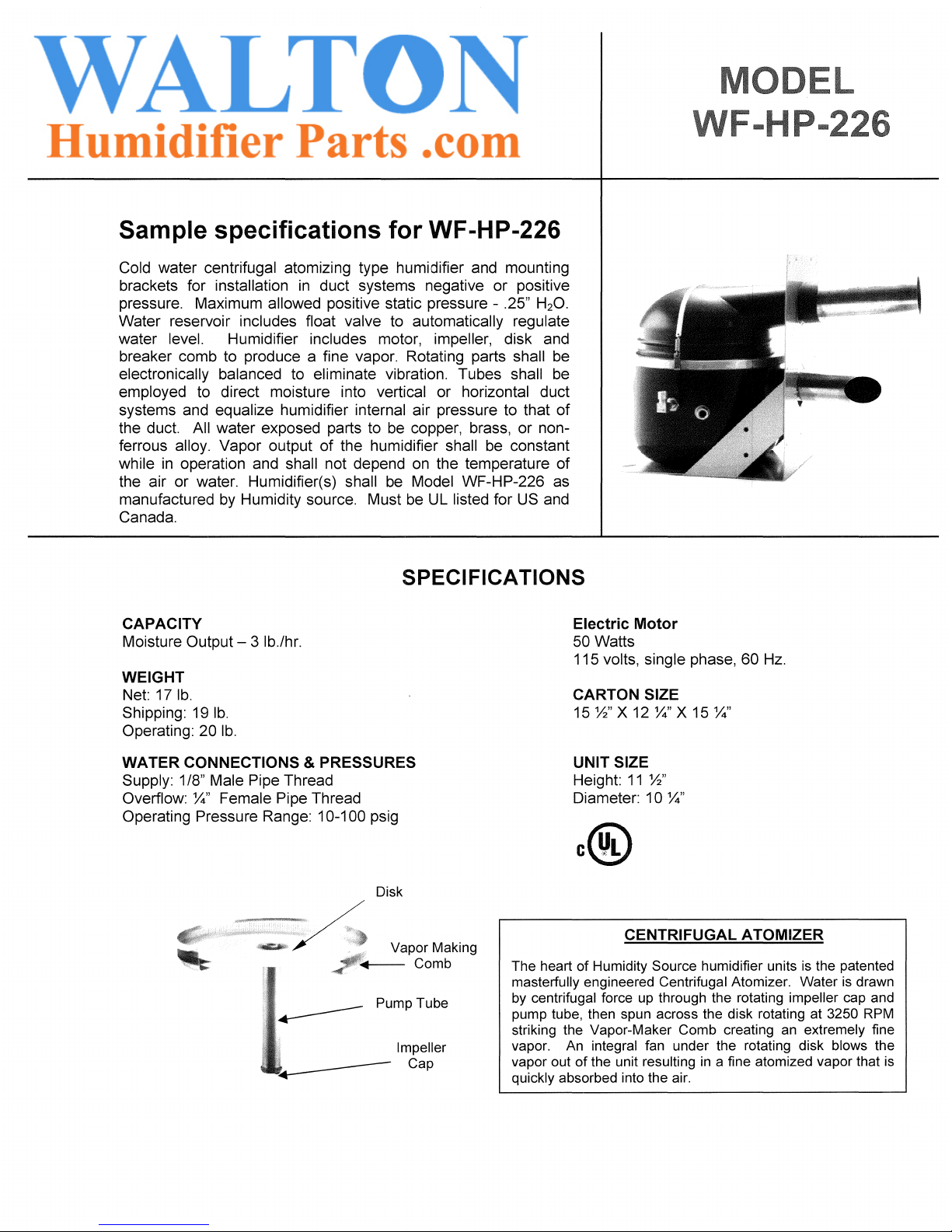
Disk
Vapor Making
7+---
Comb
Pump
Tube
Impeller
Cap
Electric Motor
50 Watts
115
volts, single phase, 60
Hz.
CARTON SIZE
15
Yz"
X 12
%"
X 15
%"
UNIT SIZE
Height:
11
Yz"
Diameter: 1 0
%"
CENTruFUGALATOM~ER
The heart of Humidity Source humidifier units
is
the patented
masterfully engineered Centrifugal Atomizer. Water is drawn
by
centrifugal force up through the rotating impeller cap and
pump tube, then spun across the disk rotating at
3250 RPM
striking the Vapor-Maker Comb creating an extremely fine
vapor. An
integral fan under the rotating disk blows the
vapor out
of
the unit resulting
in
a fine atomized vapor that
is
quickly absorbed into the air.
A
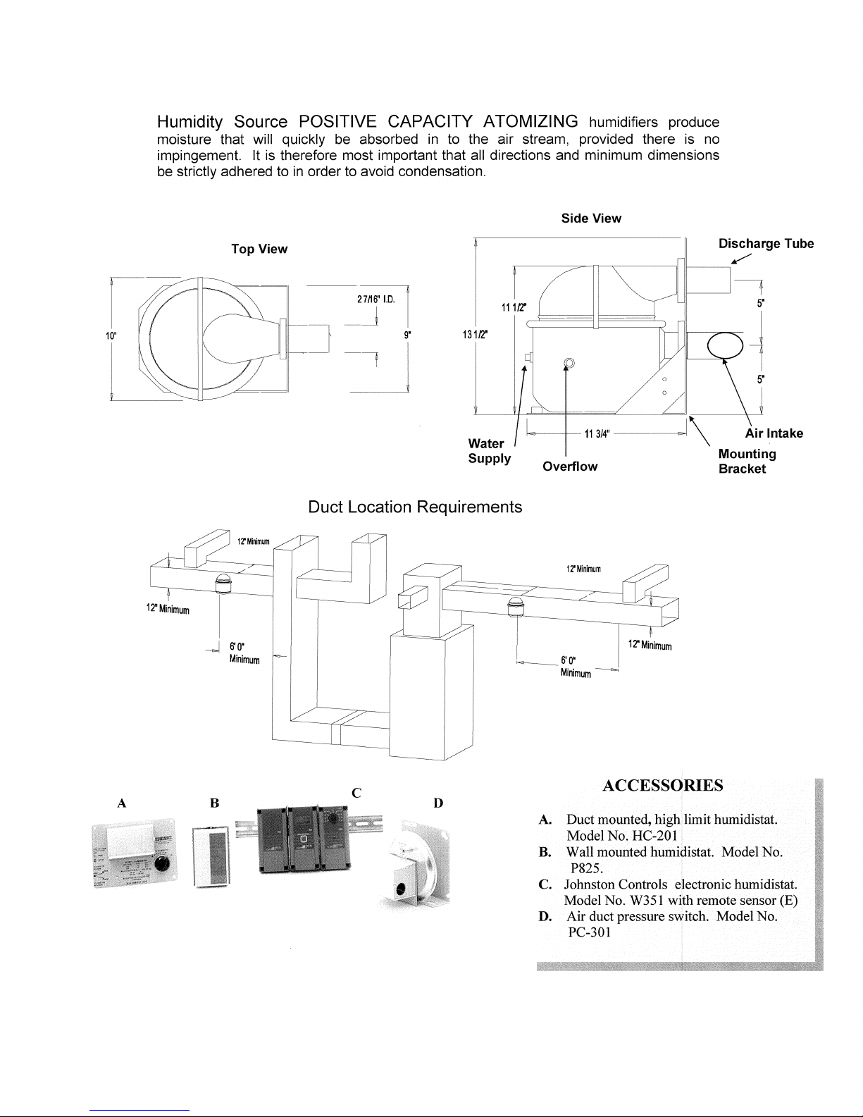
Humidity Source POSITIVE CAPACITY ATOMIZING humidifiers produce
moisture that will quickly
be
absorbed
in
to the air stream, provided there is
no
impingement. It
is
therefore most important that all directions and minimum dimensions
be
strictly adhered to
in
order to avoid condensation.
12'Minimum
Top View
-I
6'0'
Minimum
27/16"
1.0.
I
-~
_f
~
13112"
Water
Supply
Side
View
Discharge Tube
/"
11------;
~-+--11
314"
-------Is
I \
Air
Intake
Overflow
Mounting
Bracket
Duct Location Requirements
C
12'Minimum
__
6'0'
Minimum-
12'Minimum
ACCESSORIES
A. Duct mounted, high: limit humidistat.
Model No. HC-2011
B. Wall mounted humidistat. Model No.
P825.
C. Johnston Controls electronic humidistat.
Model No. W351 with remote sensor
(E)
D. Air duct pressure switch. Model No.
PC-301 !
 Loading...