


umidity Source |
MODEL |
H Quality, Selection, Support |
SW-2 |
Sample specifications for SW-2
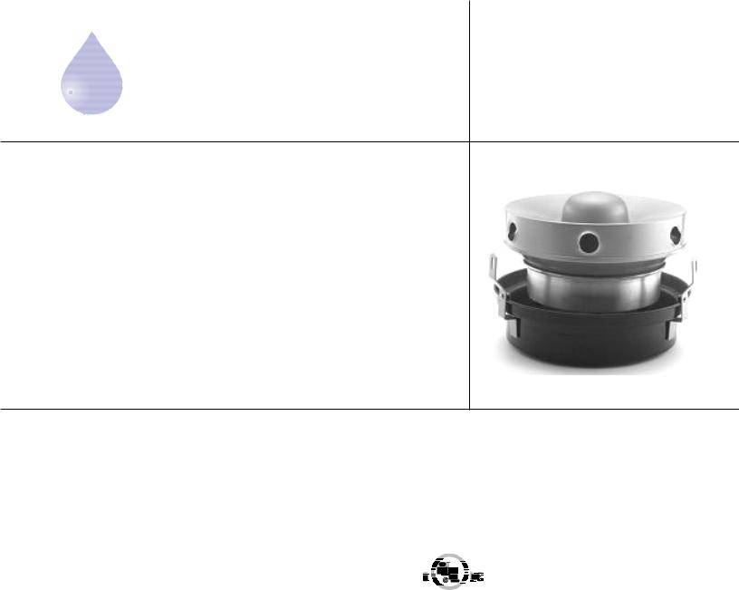
Humidifiers shall be of the high speed centrifugal atomizing type. Construction shall be of heavy gauge copper, brass and non-ferrous alloy. Heavy duty shaded pole motor with overload protection shall drive the centrifugal disc and pump assembly to draw water up from the seamless copper reservoir, against breaker combs, producing a finely atomized mist. Rotating parts shall be electronically balanced to eliminate vibration. An automatic float valve shall maintain water level in the reservoir.
Vapor output of the humidifier shall be constant while in operation and shall not depend on the temperature of the air or water.
Humidifier(s) shall be Model SW-2 as manufactured by Humidity
Source, LLC. Must be UL listed for US and Canada.
Support bracket optional
SPECIFICATIONS
CAPACITY |
Electric Motor |
||||||||||||
Moisture Output – 2 lb./hr. |
50 Watts |
||||||||||||
WEIGHT |
115 volts, single phase, 60 Hz. |
||||||||||||
|
|
|
|
|
|
|
|
|
|
|
|
|
|
Net: 10 lb. |
CARTON SIZE |
||||||||||||
Shipping: 11 lb. |
15 ½” X 12 ¼” X 15 ¼” |
||||||||||||
Operating: 15 lb. |
|
|
|
|
|
|
|
|
|
|
|
|
|
WATER CONNECTIONS & PRESSURES |
|
|
|
|
|
|
|
|
|
|
|
|
|
Supply: 1/8” Male Pipe Thread |
|
|
|
|
|
|
|
|
|
|
|
|
|
|
|
|
|
|
|
|
|
|
|
|
|
|
|
Overflow: ¼” Female Pipe Thread |
|
|
|
|
|
|
|
|
|
|
|
|
|
|
|
|
|
|
|
|
|
|
|
|
|
|
|
Operating Pressure Range: 10-150 psig |
|
|
|
|
|
|
|
|
|
|
|
|
|
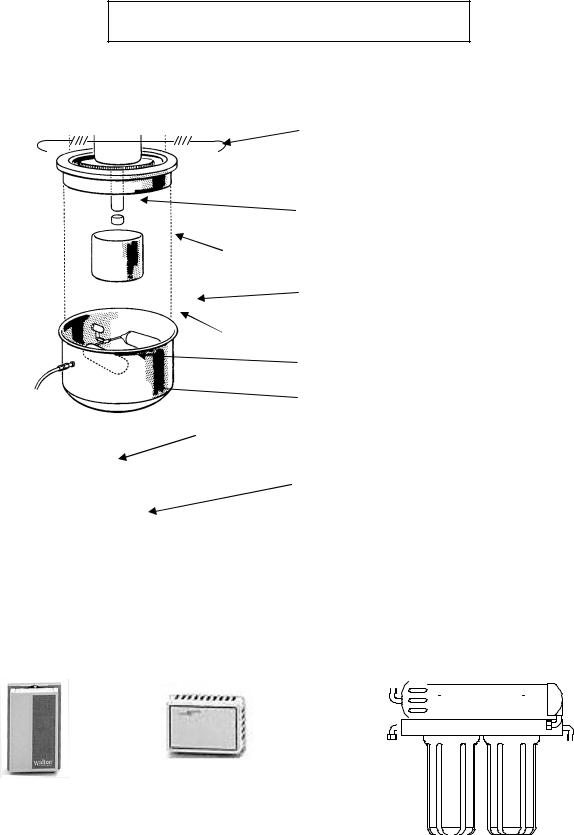
Disk
Vapor Making
Comb
Pump Tube
Impeller
Cap
CENTRIFUGAL ATOMIZER
Heart of the unit
The heart of Humidity Source humidifier units is the patented masterfully engineered Centrifugal Atomizer. Water is drawn by centrifugal force up through the rotating impeller cap and pump tube, then spun across the disk rotating at 3250 RPM striking the VaporMaker Comb creating an extremely fine vapor. An integral fan under the rotating disk blows the vapor out of the unit resulting in a fine atomized vapor that is quickly absorbed into the air.
1
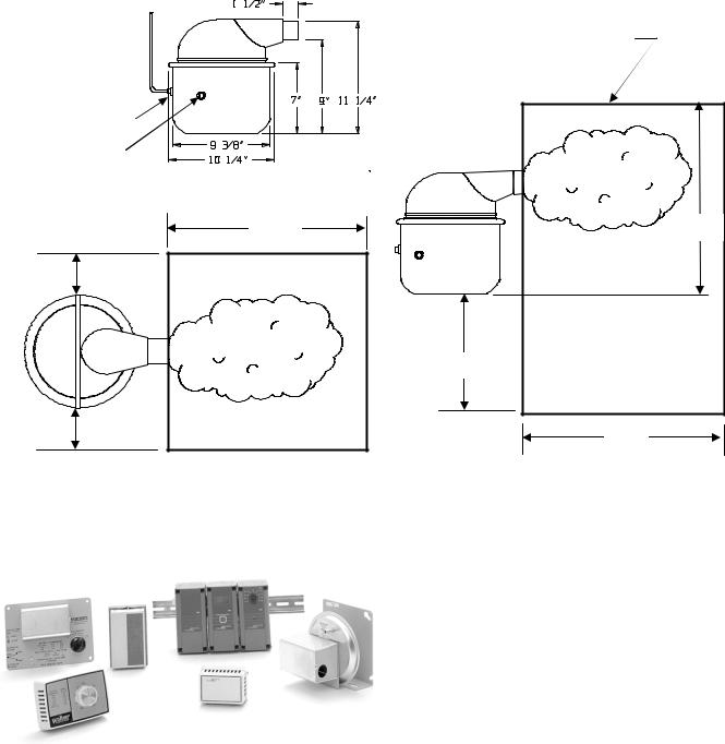
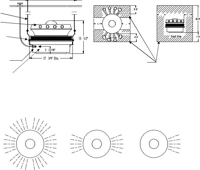
HUMIDITY SOURCE ATOMIZING humidifiers produce moisture that will quickly be absorbed in the air. However, it is very important that the humidifier be installed so that there is no chance of the moisture striking any object before it has been absorbed by the air. If any solid is hit with air containing suspended or unabsorbed moisture, condensation and dripping will result. It is therefore most important that all directions and minimum dimensions be strictly adhered to.
Water Supply
1/4” O.D. Tube
Water connection 1/8” MPT
Overflow
Connection
1/4” FPT
6’ 0”
24”
24”
No Obstruction Within
This Region To
Prevent
Wetting Objects
18” |
6’ 0” |
6’ 0” |
|
|
|
Top View |
|
|
|
Elevation |
|
|
|
|
NOTE: Drawings Not To Scale |
|||||
|
|
|
|
|
|
|
|
|
|
|
|
C |
|
|
ACCESSORIES |
|
|
|
|
|
|
|
|
|||
|
|
|
|
|
|
|
|
|
A |
|
B |
D |
|
|
A. Duct mounted, high limit humidistat. |
|
|
|
|
|
|
|
|
|||
|
|
|
|
|
|
|
Model No. HC-201 |
|
|
|
|
|
|
|
B. Wall mounted humidistat. Model No. |
|
|
|
|
|
|
|
|
C. |
P825. |
|
|
|
|
|
|
|
Johnston Controls electronic humidistat. |
|
|
|
|
|
|
|
|
D. |
Model No. W351 and remote sensor (E) |
|
|
|
|
|
|
|
|
||
|
|
|
E |
|
|
Air duct pressure switch. Model No. |
|
|
|
|
|
|
|
|
PC-301 |
|
|
|
|
|
|
|
|
|
|
|
|
|
|
|
|
|
|
||
|
|
|
|
|
|
|
|
|
|
|
|
Humidity Source, LLC |
|||||
|
|
|
||||||
|
|
|
90 Dayton Ave. Suite 58 Passaic, New Jersey 07055 |
|||||
|
|
|
TEL 973-916-1001 |
FAX: 973-916-0770 |
||||
2
umidity Source |
INSTALLATION & MAINTENANCE INSTRUCTIONS |
|
H Quality, Selection, Support |
|
|
|
|
|
MODEL SW-2
Your humidifier has been designed and engineered to give, with proper care, many years of trouble free service. Therefore, if this unit ceases to operate properly, we suggest you contact your local dealer. If we, at Humidity Source, can be of any assistance to you, please feel free to write, call or e-mail.
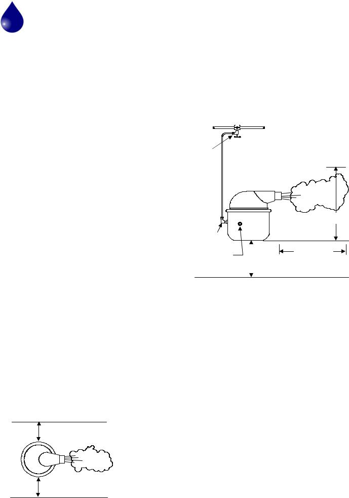
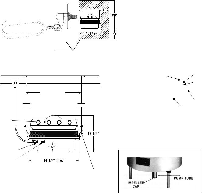
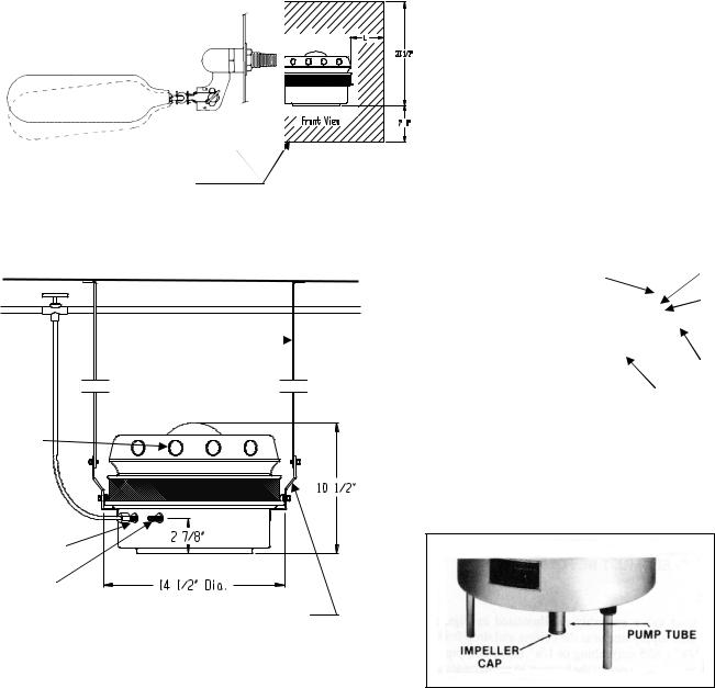
IMPORTANT
This space type humidifier is designed so that it may be shelf mounted. The shelf should be at least 18” (45.7cm) below the ceiling and 6 feet (1.8m) above floor. The directional vapor dome should be positioned to diffuse moisture without striking any obstructions closer than six feet and maintain 24” minimum between each side of the humidifier and any wall or obstruction.
PROCEDURE
Run a water supply line using 1/4” o.d. copper or plastic tubing or 1/8” pipe. Keep the line to the rear of the unit to avoid creating an obstruction.
Flush water feed lines before making final connection to avoid having cutting oil, pipe scale, or chips which may clog the float valve.
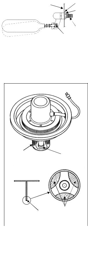
Turn on water valve and adjust water level to 1/2” below the overflow connection by adjusting the thumb screw as shown in Figure 1.
Adjustment is easily made using the adjusting thumb screw for higher or lower water level as illustrated.
SERVICE & REPAIR
Should this humidifier need service or repair some time in the future, return only atomizing unit direct to the factory.
CARE OF THE MACHINE
Due to air washing while the humidifier is in operation, a deposit of dirt and dust may settle in the bottom of the water reservoir and screen, and it is recommended that both be cleaned regularly.
24”
Top View
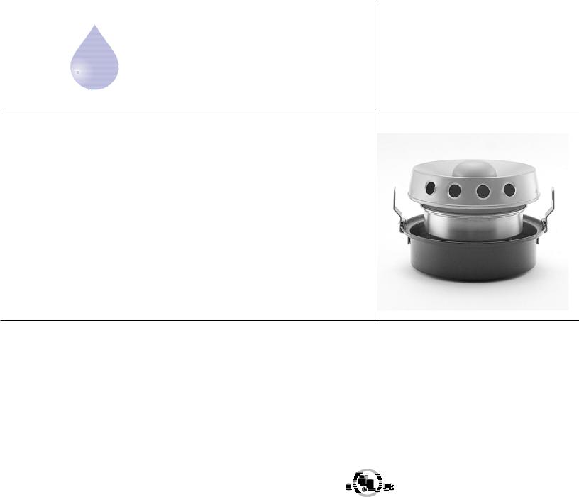
IN ROOM MOUNTED HUMIDIFIER
Periodically the atomizing unit should be taken from the reservoir and given a careful visual check. The pump tube should be spun by hand to make sure that it is free to revolve without binding. See maintenance instructions.
Typical Installation
Shut –off |
No obstruction within |
|
the dimensions indicated to |
||
valve |
||
prevent wetting objects. |
||
|
Ceiling
¼” water supply 
18”
¼” comp. |
|
|
connection |
|
|
water supply |
6’ Minimum |
|
¼” female pipe |
||
To Wall |
||
overflow connection |
6’ Minimum |
|
to drain |
To Floor |
WIRING
The atomizer motor draws .67 Amps at 115 Volts A.C. single phase and 60 Hz service.
Provide standard electric receptacle to receive electric cord from humidifier. Have the hot leg of service to this receptacle wired in series with the humidistat terminals and use a standard disconnect switch if required. See wiring diagram.
This humidifier may be run continuously or operated by means of a humidistat.
Our standard human hair element humidistat model P- 825 is correct for most applications maintaining up to 60% RH.
For humidors and other high humidity applications, or for more precise control, use the electronic humidistat model W351A. This model also has an optional digital display module to indicate the set point and the actual R.H. in the room.
24”
3
|
|
Reservoir Wall |
|
Mounting |
|
Float Valve Operation |
|
Washer |
|
|
|
|
||
|
Pressure Range |
|
|
Mounting |
|
10-150 psig |
|
|
|
|
|
|
Nut |
|
|
|
|
|
|
|
|
|
|
1/8” MPT |
|
|
|
Adjusting |
|
|
|
|
Thumb Screw |
|
|
|
|
|
|
Figure 1
Atomizing Unit
 Pump Tube
Screen
Impeller Cap
2-A
Sight into bottom of tube 
Remove impeller |
|
These openings |
|
must be clear |
|
cap |
|
|
|
|
|
2-B |
|
2-C |
|
|
|
|
FIGURE 2 |
|
OPERATION
Positive capacity atomizing humidifiers produce a mist that will quickly evaporate into the air if there is no impingement of water particles against barrier surfaces before the water particles against barrier surfaces before the water is completely absorbed. Strict attention to minimum clearance dimensions must be adhered to in order to avoid condensation.
MAINTENANCE
Unplug electric cord & remove dome. Carefully lift atomizing unit out of reservoir (Figure 2). Hold atomizing unit firmly and remove the perforated screen (2-A) by turning it slightly to the left until the four lugs are in line with the slots. To remove the impeller cap (2-B), hold a flat file or the back of a table knife flat against the side of the tube and gently tap the cap which is held in place by a pressed fit. After the cap has been removed, the inside of the tube is visible and it is simple matter to clean it with a piece of cloth on the end of a screwdriver or a small round brush.
There are three ports through which water makes its way from the pump tube to the top of the rotating disc (2-C). These ports should be cleaned out with the aid of a wire. See drawing on this page.
Replace the impeller cap by tapping it evenly back into place, using plastic handle on screwdriver.
Remove water from reservoir & rinse. Fill reservoir with white vinegar or other mild acid solution. Replace dome & atomizer on reservoir & block outlet of dome with plastic wrap & a rubber band. Run atomizer for ½ hour or until minerals are completely dissolved. If necessary, rinse with diluted chlorine bleach solution. Rinse with clean water and return to service. For hard water problems, see “demineralized water” below.
Inspect float valve assemble periodically, & replace when necessary, or every few years. Should this humidifier need service or repair some time in the future, return only atomizing unit direct to the factory.
DEMINERALIZED WATER
If your local water supply has a high mineral content, (call water company & ask for “total dissolved solids” or T.D.S.) This mineral will create tiny particles of airborne “white dust” when the mist evaporates in the air. To eliminate this dust, use an ion exchange or a reverse osmosis demineralizer. See Humidity Source data sheets for Reverse Osmosis demineralizing filters.
4
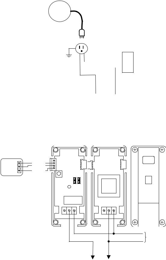
Wiring Diagram If Using P-825 Humidistat Installation
Humidifier
Receptacle
Humidity Source P-825
Wall Humidistat
 H
H
 L
L
 C
C
120 VAC
L2 L1
Neutral Hot
W351A Wiring Diagram If Using W351 On/Off Controller
W351 Humidistat
Electronic Sensor
COM |
COM |
PWR |
VDC |
OUT |
SEN |
Controller |
Power Module |
Digital Display |
W351A |
Y350R |
D351 |
120 VAC
To Humidifier
5
MODEL SW-2 REPLACEMENT PARTS
|
|
|
|
|
|
|
Description |
Part Number |
|
|
|
|
|
|
|
Dome Strap Assembly |
079590 |
|
|
|
|
|
|
|
Dome |
905026 |
|
|
|
|
|
|
|
Channel Rubber |
905582 |
|
|
|
|
|
|
|
||
|
|
|
|
|
|
|
Atomizing Assembly |
WF/525/9/2 |
|
|
|
|
|
|
|
Rubber Mounts (3) |
80096 |
|
|
|
|
|
|
|||
|
|
|
|
|
|
|
Impeller Cap |
905587 |
|
|
|
|
|
|
|
Cylindrical Screen |
905543 |
|
|
|
|
|
|
|
Float Valve Assembly |
079057 |
|
|
|
|
|
|
|||
|
|
|
|
|
|
|
Reservoir |
905608 |
|
|
|
|
|
|
|
|
|
|
|
|
|
|
|
|
|
|
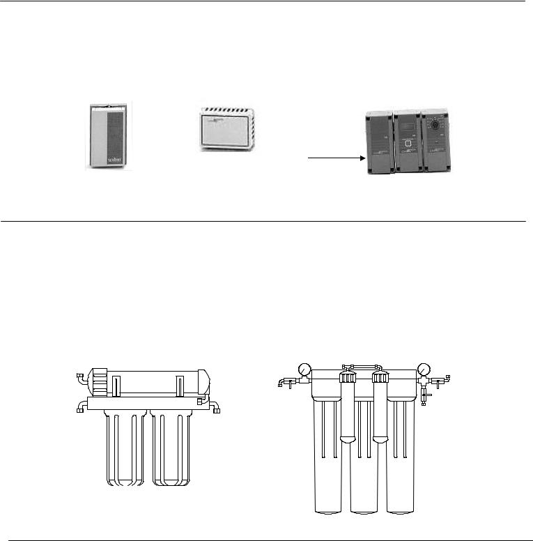
Humidifier Accessories
P-825 Humidistat |
W351 Humidistat |
Humidity Source Reverse Osmosis water |
||||||||||||||||||
Treatment systems. Sizes range from industrial |
||||||||||||||||||||
Human Hair Element |
Electronic Sensor |
capacities down to individual room units. |
||||||||||||||||||
|
|
|
|
|
|
|
|
|
|
|
|
|
|
|
|
|
|
|
|
|
|
|
|
|
|
|
|
|
|
|
|
|
|
|
|
|
|
|
|
|
|
|
|
|
|
|
|
|
|
|
|
|
|
|
|
|
|
|
|
|
|
|
|
|
|
|
|
|
|
|
|
|
|
|
|
|
|
|
|
|
|
|
|
|
|
|
|
|
|
|
|
|
|
|
|
|
|
|
|
|
|
|
|
|
|
|
|
|
|
|
|
|
|
|
|
|
|
|
|
|
|
|
|
|
|
|
|
|
|
|
|
|
|
|
|
|
|
|
|
|
|
|
|
|
|
|
|
|
|
|
|
|
|
|
|
|
|
|
|
|
|
|
|
|
|
|
|
|
|
|
|
|
|
|
|
|
|
|
|
|
|
|
|
|
|
|
|
|
For high humidity
Standard And/or close tolerances
Humidity Source LLC
90 Dayton Ave.Suite 58, Passaic, New Jersey 07055
Phone 973-916-1001 e-mail HumiditySource@aol.com
6
umidity Source |
MODEL |
H Quality, Selection, Support |
SF-5/SW-5 |
Sample specifications for SF-5/SW-5
Cold water centrifugal atomizing type humidifier and mounting brackets for installation overhead. Water level reservoir includes valve to automatically regulate water flow. Atomizer includes motor, impeller, disc and breaker comb to produce a fine vapor and introduce moisture with a small amount of air through the vapor dome to the surroundings. All water exposed parts to be copper, brass or non-ferrous alloy.
The SF5 includes an air filter to protect atomizing unit from dust, lint etc. in the small amount of primary air that passes through the atomizer. Must be UL listed for US and Canada.
SPECIFICATIONS
CAPACITY
Moisture Output – 5 lb./hr.
WEIGHT
Net: 25 lb.
Shipping: 28 lb.
Operating: 36 lb.
DIMENSIONS
Height: 10 ½”
Diameter: 14 ½”
WATER CONNECTIONS & PRESSURES
Supply: 1/8” Male Pipe Thread Overflow: ¼” Female Pipe Thread Operating Pressure Range: 10-100 psig.
Electric Motor
.76 amps
115 volts, 1 ph – 50/60 Hz.
3250 RPM
CARTON SIZE
Unit: 12” x 20” x 18”
Dome: 13 3/4” x 10 ¼” x 19 ¼”
Notes:
SF Models equipped with filters of a washable, replaceable filter media type. Proper dome selection must be made.
These specification are subject to change without Notice. Mounting brackets supplied with units.
7

Humidity Source ATOMIZING humidifiers produce moisture that will quickly be absorbed in to the air, However, It is very important that the humidifier be installed so there is on chance of the moisture striking any object before it has been absorbed in the air. If any solid object is hit with air containing suspended or absorbed moisture, condensation and dripping will result. It is therefore most important that all directions and minimum dimensions be strictly adhered to.
APPLICATION NOTES:
1.Allow minimum distance of un-obstructive space around humidifier for moisture to be absorbed into the air as shown in diagram.
2.Operation is by means of P-825 wall mounted humidistat with human hair sensing element. Order separately.
3.If water supply is hard, install a demineralizer in water in water line to prevent “white dust” from being formed.
4.When ordering, choose proper dome (see below).
Ceiling Line
Hanging straps by contractor
Dome ports
Hanging bracket  supplied

Water supply
1/8” male pipe thd.
Over flow
¼” female pipe thd.
Note: Drawing not to scale
Two way Dome shown
No obstruction within this region To prevent wetting object for
One and Two way Domes, L = 41” For Standard Dome, L = 6’ 0”
IMPORTANT: Select proper Dome to avoid condensation on obstructions.
Standard Dome |
Two way directional Dome One way Directional Dome |
Shelf mounted use |
|
For one way Dome |
|||
|
|
Humidity Source, LLC
90 Dayton Ave. Suite 58 Passaic, New Jersey 07055 TEL 973-916-1001 FAX: 973-916-0770
8

umidity Source |
|
INSTALLATION AND MAINTENANCE INSTRUCTIONS |
|
H Quality, Selection, Support |
|
|
MODEL SF-5 and SW-5
GENERAL INFORMATION
This space type humidifier is designed to be suspended from the ceiling or mounted on a shelf. Hanging brackets are provided but supports from the ceiling or shelf must be furnished by others.
The humidifier consists of two assemblies; the water reservoir which includes a float type water level valve with 1/8” male pipe thread connection and a safety overflow port and the atomizer assembly which is a delicately balanced, completely self-contained unit that rests in the water reservoir and supports the directional vapor distribution dome.
PROCEDURE
When selecting exact location for each humidifier be sure that the vapor discharge is approximately six feet from the any obstruction such as lights, pipes or beams. Vapor must also avoid touching humidifier wiring and supports. The following procedure is recommended.
1.Obtain the correct type of vapor distribution dome for each humidifier location.
2.At each location place the correct dome in the reservoir and install one hanging bracket above the water inlet valve, above the position of the water valve on the side of the tank. Then rotate and position the dome so that its vapor ports will avoid this bracket.
3.Place the other hanging brackets in a position which will give level, secure suspension and at the same time will avoid striking the hangers which are to be attached to these brackets.
4.After positioning the reservoir to avoid vapor touching any existing obstructions, locate points on the ceiling directly above the brackets and connect suspension straps or rods at these points. See Figure “B” for further details.
NOTE: ALL MINIMUM INSTALLATIONS DIMENSIONS AS SHOWN IN FIGURE “A” MUST BE FOLLOWED.
PLUMBING
Insert the float valve assembly as illustrated in Figure “C”. Run a water supply line near the
9
ceiling and drop a 1/4" tubing line ( or 1/8” pipe) from the supply line. Keep the drop very close to one of the hangers to avoid creating an obstruction.
Flush all water feed lines before making final connections to avoid clogging the float valve with foreign matter.
Adjust the position of float valve stem to establish a water level in the reservoir about 1/2” below the overflow fitting. See Figure “C” for location of adjusting screw.
Be sure that the water valve arm is directed toward the center of the reservoir when tightening the mounting nut.
FOR MODELS WITH FILTER
Place the filter in the reservoir with wide flange on top, and the notch directly above marker near water inlet position. Place atomizer assembly into this flange positioned so that the motor extension cord matches the notch in the flange. This avoids the possibility of atomizer legs interfering with the operation of the water regulating valve.
Place vapor dome over the atomizer assembly and run electric cord along one hanger to a female receptacle. Wiring to the receptacle should be through a humidistat control that will operate the humidifier. Refer to Figure “E” for wiring diagram.
Due to a certain amount of “air-washing” when the humidifier is operating, an accumulation of dust and dirt may settle at the bottom of the reservoir. It is therefore recommended that periodic inspection and cleaning be performed as necessary. Also the water drain plug or valve should be opened frequently and the water line flushed out. This periodic maintenance can greatly extend the life of the humidifier.
IMPORTANT:
IT IS NECESSARY TO KEEP THE RESERVOIR AND ATOMIZER UNIT CLEAN IN ORDER TO MAINTAIN FULL HUMIDIFIER CAPACITY AND NOT OVERLOAD THE MOTOR.
MAINTENANCE
As stated above, the water reservoir and pump tube must be kept clean and free of minerals, scale and dust. Periodically remove atomizer assembly and clean reservoir with white vinegar. Carefully remove impeller cap (see Figure “D”) and clean pump tube with pipe cleaner or test tube brush. Motors have sealed bearings and do not require lubrication.
SERVICE
Atomizer motors are sealed in a copper housing at the top of the atomizer assembly. DO NOT BREAK THIS SEAL. If for any reason a repair becomes necessary, carefully package the entire atomizer assembly and return intact to your installer, local distributor or Humidity Source, LLC. When ordering parts have model number and voltage available.
Positive Capacity Atomizing Humidifiers produce a fine vapor that will quickly evaporate in the air if there is no impingement of water particles against obstructions before absorption is complete. Strict attention to minimum clearance dimensions must be adhered to in order to avoid condensation.
Two Way Dome Shown
No obstacle within this region to prevent wetting objects
For one and two way domes, L = 41”
For standard dome, L = 6’ – 0” Figure A
Hanging straps
By contractor
Dome Ports
Water supply 1/8” MPT
Overflow
1/4" FPT
|
Brackets Supplied |
|
Figure B |
by Humidity Source |
|
GENERAL NOTES:
1.Water reservoir must be level.
2.Keep water supply piping close to hanging strap.
3.Use a humidistat for automatic operation.
4.Use Reverse Osmosis for poor quality water.
FLOAT VALVE
|
|
Reservoir Wall |
|
Mounting |
|
Float Valve Operation |
|
Washer |
|
|
|
|
||
|
Pressure Range |
|
|
Mounting |
|
10-150 psig |
|
|
|
|
|
|
Nut |
|
|
|
|
|
|
|
|
|
|
1/8” MPT |
|
|
|
Adjusting |
|
|
|
|
Thumb Screw |
|
|
|
|
|
|
Figure C
Figure D
10
Wiring Diagram For P-825 Humidistat
Humidifier
W351 Humidistat
Electronic Sensor
COM |
COM |
PWR |
VDC |
OUT |
SEN |
Receptacle
Humidity Source P-825
Wall Humidistat
 H
H
 L
L
 C
C
120 VAC
L2 L1
Neutral Hot
W351A Wiring Diagram – On/Off Control
Controller |
Power Module |
Digital Display |
W351A |
Y350R |
D351 |
120 VAC
To Humidifier
11
Humidifier Accessories
Humidistats, Sensors & Controls
P-825 Humidistat |
W351 Humidistat |
|
|||
Human Hair Element |
Electronic Sensor |
W351 ELECTRONICHUMIDITY |
|||
|
|
|
|
|
CONTROL With Digital Display |
|
|
|
|
|
|
|
|
|
|
|
|
|
|
|
|
|
|
For high humidity
Standard And/or close tolerances
Reverse Osmosis Demineralizers
Humidity Source Reverse Osmosis
water Treatment systems. Sizes range from industrial capacities down to individual room units.
|
RO-120 |
RO-24 |
RO-450 |
RO-900 |
Humidity Source LLC
90 Dayton Ave. Suite 58, Passaic, New Jersey 07055
Phone 973-916-1001 e-mail HumiditySource@aol.com
12
MODEL
H umidity Source SF-10/SW-10
Quality, Selection, Support
SF-10B/SW-10B
Sample specifications for SF-10/SW-10 & SF-10B/SW-10B
Cold water centrifugal atomizing type humidifier and mounting brackets for installation overhead. Water reservoir includes valve to automatically regulate water flow. Atomizer includes motor, impeller, disc and breaker comb to produce a fine vapor and introduce moisture with a small amount of air through the vapor dome to the surroundings. All water exposed parts to be copper, brass or non-ferrous alloy.
SF10 includes an air filter to protect atomizing unit from dust, lint etc. in the small amount of primary air that passes through the atomizer. Must be UL listed for US and Canada.
SPECIFICATIONS
CAPACITY
Moisture Output – 10 lb./hr.
WEIGHT
Net: 28 lb.
Shipping: 31 lb.
Operating: 40 lb.
WATER CONNECTIONS & PRESSURES
Supply: 1/8” Male Pipe Thread Overflow: ¼” Female Pipe Thread Operating Pressure Range: 10-100 psig.
Electric Motor
Model SF-10 & SW-10
1.15 amps, 115 volts, 1 ph – 50/60 hz. Model SF-10B & SW-10B
.55 AMPS, 220 volts, 1 ph – 50/60 hz.
Notes:
SF Models equipped with filters of a washable, replaceable filter media type. Proper dome selection must be made.
These specification are subject to change without Notice. Mounting brackets supplied with units.
13
Humidity Source ATOMIZING humidifiers produce moisture that will quickly be absorbed in to the air, However, It is very important that the humidifier be installed so there is on chance of the moisture striking any object before it has been absorbed in the air. If any solid object is hit with air containing suspended or absorbed moisture, condensation and dripping will result. It is therefore most important that all directions and minimum dimensions be strictly adhered to.
Hanging straps by contractor
Dome ports
Hanging bracket supplied
Water supply
1/8” male pipe thd.
Over flow
¼” female pipe thd.
Ceiling Line |
|
Note: Drawing not to scale |
||||||||||||||
|
|
|
|
|
|
|
|
|
|
|
|
|
|
|
|
|
|
|
|
|
|
|
|
|
|
|
|
|
|
|
|
|
|
|
|
|
|
|
|
|
|
|
|
|
|
|
|
|
|
|
|
|
|
|
|
|
|
|
|
|
|
|
|
|
|
|
|
|
|
|
|
|
|
|
|
|
|
|
|
|
|
|
|
|
|
|
|
|
|
|
|
|
|
|
|
|
|
|
|
|
|
Two way Dome shown
No obstruction within this region
To prevent wetting object for
One and Two way Domes, L = 41”
For Standard Dome, L = 6’ 0”
IMPORTANT: Select proper Dome to avoid condensation on obstructions.
Standard Dome |
Two way directional Dome |
One way Directional Dome |
Humidity Source, LLC
90 Dayton Ave. Suite 58, Passaic, New Jersey 07055 TEL 973-916-1001 FAX: 973-916-0770
14

umidity Source |
INSTALLATION AND MAINTENANCE INSTRUCTIONS |
H Quality, Selection, Support |
MODEL SF-10, SF-10B, and SW-10, SW-10B
GENERAL INFORMATION
This space type humidifier is designed to be suspended from the ceiling or mounted on a shelf. Hanging brackets are provided but supports from the ceiling or shelf must be furnished by others.
The humidifier consists of two assemblies; the water reservoir which includes a float type water level valve with 1/8” male pipe thread connection and a safety overflow port and the atomizer assembly which is a delicately balanced, completely self-contained unit that rests in the water reservoir and supports the directional vapor distribution dome.
PROCEDURE
When selecting exact location for each humidifier be sure that the vapor discharge is approximately six feet from the any obstruction such as lights, pipes or beams. Vapor must also avoid touching humidifier wiring and supports. The following procedure is recommended.
1.Obtain the correct type of vapor distribution dome for each humidifier location.
2.At each location place the correct dome in the reservoir and install one hanging bracket above the water inlet valve, above the position of the water valve on the side of the tank. Then rotate and position the dome so that its vapor ports will avoid this bracket.
3.Place the other hanging brackets in a position which will give level, secure suspension and at the same time will avoid striking the hangers which are to be attached to these brackets.
4.After positioning the reservoir to avoid vapor touching any existing obstructions, locate points on the ceiling directly above the brackets and connect suspension straps or rods at these points. See Figure “B” for further details.
NOTE: ALL MINIMUM INSTALLATIONS DIMENSIONS AS SHOWN IN FIGURE “B” MUST BE FOLLOWED.
PLUMBING
Insert the float valve assembly as illustrated in Figure “C”. Run a water supply line near the ceiling and drop a 1/4" tubing line ( or 1/8” pipe) from the
supply line. Keep the drop very close to one of the hangers to avoid creating an obstruction.
Flush all water feed lines before making final connections to avoid clogging the float valve with foreign matter.
Adjust the position of float valve stem to establish a water level in the reservoir about 1/2” below the overflow fitting. See Figure “C” for location of adjusting screw.
Be sure that the water valve arm is directed toward the center of the reservoir when tightening the mounting nut.
FOR MODELS WITH FILTER
Place the filter in the reservoir with wide flange on top, and the notch directly above marker near water inlet position. Place atomizer assembly into this flange positioned so that the motor extension cord matches the notch in the flange. This avoids the possibility of atomizer legs interfering with the operation of the water regulating valve.
Place vapor dome over the atomizer assembly and run electric cord along one hanger to a female receptacle. Wiring to the receptacle should be through a humidistat control that will operate the humidifier. Refer to Figure “E” for wiring diagram.
Due to a certain amount of “air-washing” when the humidifier is operating, an accumulation of dust and dirt may settle at the bottom of the reservoir. It is therefore recommended that periodic inspection and cleaning be performed as necessary. . Also the water drain plug or valve should be opened frequently and the water line flushed out. This periodic maintenance can greatly extend the life of the humidifier.
IMPORTANT:
IT IS NECESSARY TO KEEP THE RESERVOIR AND ATOMIZER UNIT CLEAN IN ORDER TO MAINTAIN FULL HUMIDIFIER CAPACITY AND NOT OVERLOAD THE MOTOR.
MAINTENANCE
As stated above, the water reservoir and pump tube must be kept clean and free of minerals, scale and dust. Periodically remove atomizer assembly and clean reservoir with white vinegar. Carefully remove impeller cap (see Figure “D”) and clean pump tube with pipe cleaner or test tube brush.
15
Motors have sealed bearings and do not require lubrication.
SERVICE
Atomizer motors are sealed in a copper housing at the top of the atomizer assembly. DO NOT BREAK THIS SEAL. If for any reason a repair becomes necessary, carefully package the entire atomizer assembly and return intact to your installer, local distributor or Humidity Source, LLC. When ordering parts have model number and voltage available.
Positive Capacity Atomizing Humidifiers produce a fine vapor that will quickly evaporate in the air if there is no impingement of water particles against obstructions before absorption is complete. Strict attention to minimum clearance dimensions must be adhered to in order to avoid condensation.
Two Way Dome Shown
No obstacle within this region to prevent wetting objects
For one and two way domes, L = 41” |
Figure A |
For standard dome, L = 6’ – 0” |
Hanging straps
 By contractor
Dome Ports
Water supply 1/8” MPT
Overflow
1/4" FPT
Brackets Supplied
by Humidity Source
Figure B
GENERAL NOTES:
1.Water reservoir must be level.
2.Keep water supply piping close to hanging strap.
3.Use a humidistat for automatic operation.
4.Use Reverse Osmosis for poor quality water.
FLOAT VALVE
|
|
Reservoir Wall |
|
Mounting |
|
Float Valve Operation |
|
Washer |
|
|
|
|
||
|
Pressure Range |
|
|
Mounting |
|
10-150 psig |
|
|
|
|
|
|
Nut |
|
|
|
|
|
|
|
|
|
|
1/8” MPT |
|
|
|
Adjusting |
|
|
|
|
Thumb Screw |
|
|
|
|
|
|
Figure C
Figure D
16
 Loading...