

Walton SF-5, SW-5 Installation And Maintenance Manual
GENERAL INFORMATION
This space type humidifier
is
designed to be
suspended from the
ceiling or mounted
on
a shelf.
Hanging brackets are provided but supports from the
ceiling or shelf must
be
furnished
by
others.
The humidifier consists
of
two assemblies; the water
reservoir which includes a
float type water level valve
with 1/8" male pipe thread connection and a safety
overflow port and the atomizer assembly which
is
a
delicately balanced, completely self-contained unit
that rests
in
the water reservoir and supports the
directional vapor distribution dome.
PROCEDURE
When selecting exact location for each humidifier be
sure that the vapor discharge
is
approximately six feet
from the any obstruction such as
lights, pipes or
beams. Vapor must
also avoid touching humidifier
wiring and supports. The
following procedure
is
recommended.
1.
Obtain the correct type
of
vapor distribution
dome for each humidifier
location.
2.
At each location place the correct dome
in
the
reservoir and
install one hanging bracket
above the water
inlet valve, above the position
of
the water valve
on
the side
of
the tank. Then
rotate and position the dome so that its vapor
ports
will avoid this bracket.
3.
Place the other hanging brackets
in
a position
which
will give level, secure suspension and at
the same time
will avoid striking the hangers
which are to
be
attached to these brackets.
4.
After positioning the reservoir to avoid vapor
touching any existing obstructions,
locate
points
on
the ceiling directly above the
brackets and connect suspension straps or
rods at these points.
See Figure
"B"
for further
details.
NOTE:
ALL MINIMUM INSTALLATIONS
DIMENSIONS AS SHOWN
IN
FIGURE "A" MUST
BE
FOLLOWED.
PLUMBING
Insert
the float valve assembly as illustrated
in
Figure
"C".
Run
a water supply line near the
ceiling and drop a 1/4" tubing line ( or 1/8" pipe)
from the
supply line. Keep the drop very close to
one of the hangers to avoid creating
an
obstruction.
Flush all water feed lines before making final
connections to avoid clogging the float valve with
foreign matter.
Adjust the position of
float valve stem to establish a
water
level
in
the reservoir about 1/2" below the
overflow fitting. See Figure
"c"
for location of
adjusting screw.
Be sure that the water
valve arm
is
directed toward
the center of the reservoir when tightening the
mounting nut.
FOR MODELS WITH FILTER
Place
the filter
in
the reservoir with wide flange
on
top, and the notch directly above marker near
water
inlet position. Place atomizer assembly into
this
flange positioned so that the motor extension
cord matches the notch
in
the flange. This avoids
the
possibility of atomizer legs interfering with the
operation
of
the water regulating valve.
Place
vapor dome over the atomizer assembly and
run
electric cord along one hanger to a female
receptacle. Wiring to the receptacle should
be
through a humidistat control that will operate the
humidifier. Refer to Figure
"E" for wiring diagram.
Due to a certain amount of
"air-washing" when the
humidifier
is
operating, an accumulation
of
dust
and dirt may settle at the bottom
of
the reservoir. It
is
therefore recommended that periodic inspection
and
cleaning
be
performed as necessary. Also the
water drain
plug or valve should
be
opened
frequently and the water line flushed out. This
periodic maintenance can
greatly extend the life of
the humidifier.
IMPORTANT:
IT IS NECESSARY TO
KEEP THE RESERVOIR
AND ATOMIZER UNIT CLEAN
IN
ORDER TO
MAINTAIN
FULL HUMIDIFIER CAPACITY AND
NOT OVERLOAD THE MOTOR.
MAINTENANCE
As stated above, the water reservoir and pump
tube must be kept
clean and free
of
minerals, scale
and dust. Periodically remove atomizer assembly
and clean reservoir with white vinegar. Carefully
remove impeller cap (see Figure "0") and clean
pump tube with pipe
cleaner or test tube brush.
Motors have
sealed bearings and do not require
lubrication.
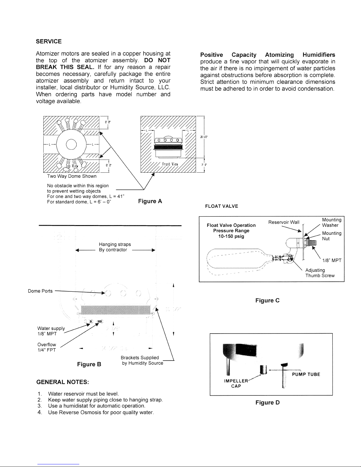
SERVICE
Atomizer motors are sealed
in
a copper housing at
the top of the atomizer
assembly.
DO
NOT
BREAK THIS SEAL. If for any reason a repair
becomes necessary,
carefully package the entire
atomizer
assembly and return intact to your
installer, local distributor or Humidity Source,
LLC.
When ordering parts have model number and
voltage available.
No obstacle within this region
to prevent wetting objects
For one
and
two way domes, L = 41"
For standard dome, L = 6' -
0"
Hanging straps
Figure A
By contractor
------1~.
/
DomePorts--------https://manualmachine.com/~~~~~C;
: =
~l
:."
"
~~
~/
watersupp~y
~
1/8"MPT
~./
Overflow
1/4" FPT
--
I
//
Brackets Supplied
Figure B by Humidity Source
GENERAL NOTES:
1.
Water reservoir must
be
level.
2.
Keep water supply piping close to hanging strap.
3.
Use a humidistat for automatic operation,
4. Use Reverse
Osmosis for poor quality water.
"
//
Positive Capacity Atomizing Humidifiers
produce a fine vapor that will quickly evaporate
in
the air if there is no impingement of water particles
against obstructions before absorption
is
complete.
Strict attention to minimum clearance dimensions
must
be
adhered to
in
order to avoid condensation.
FLOAT VALVE
Float Valve Operation
Pressure Range
10-150 psig
Figure C
J
Mounting
Washer
Mounting
Nut
Adjusting
Thumb Screw
/lJ
-r.~
PUMP TUBE
IMPELLERl
CAP ';
Figure D
 Loading...