

Walther VMS-13-EH-0.5, VMS-13-EH-0.3, Dosing Pen VMS-13-EH, VMS-13-EH-1.0, VMS-13-EH-1.5 Assembly Instructions Manual
Page 1
Rev. 1.2
Assembly Instructions – Dosing Pen VMS-13-EH
Page 1 of 20
Walther Systemtechnik GmbH – D 76726 Germersheim
Telefon: +49 (0)7274-7022-0 Telefax: +49 (0)7274-7022-91
http://www.walther-2000.de – info@walther-2000.de
Assembly Instructions
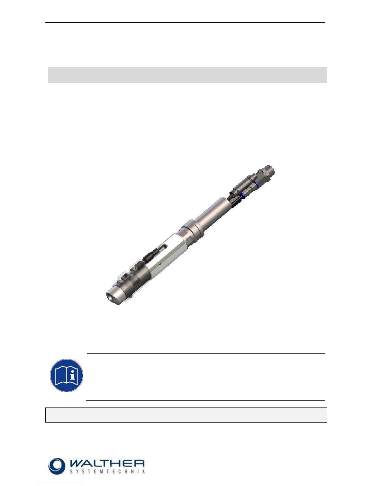
WALTHER-Dosing Pen© VMS-13-EH
Article Number: VMS-13-EH-0.3
VMS-13-EH-0.5
VMS-13-EH-1.0
VMS-13-EH-1.5
Fig.: WALTHER-Dosing Pen© VMS-13-EH
NOTE
Please read the Assembly Instructions carefully before first using the incomplete device and
strictly adhere to the instructions!
The incomplete device may only be worked with and worked on by persons who are familiar
with the assembly instructions and the current regulations for industrial safety and accident
prevention.
Always keep a translated version of the ‘original Assembly Instructions’ at the incomplete device!
The assembly instructions have to be close at hand any time!
Page 2

Rev. 1.2
Assembly Instructions – Dosing Pen VMS-13-EH
Page 2 of 20
Walther Systemtechnik GmbH – D 76726 Germersheim
Telefon: +49 (0)7274-7022-0 Telefax: +49 (0)7274-7022-91
http://www.walther-2000.de – info@walther-2000.de
Table of Contents
Page
EC DECLARATION OF INCORPORATION ....................................................................................................................... 4
1 INTRODUCTION ................................................................................................................................................. 5
1.1 TARGET GROUP OF THE ASSEMBLY INSTRUCTIONS ............................................................................................................ 5
1.2 LIST OF SIGNS AND SYMBOLS ....................................................................................................................................... 5
2 SAFETY............................................................................................................................................................... 5
2.1 GENERAL INFORMATION ............................................................................................................................................. 5
2.2 DANGERS FROM RESIDUAL ENERGY ............................................................................................................................... 5
2.3 WARRANTY AND LIABILITY ........................................................................................................................................... 5
2.4 CORRECT USE ........................................................................................................................................................... 6
2.5 INCORRECT USE ........................................................................................................................................................ 6
2.6 QUALIFICATION OF PERSONNEL .................................................................................................................................... 6
3 TRANSPORT ....................................................................................................................................................... 7
3.1 PACKAGING .............................................................................................................................................................. 7
3.2 TASKS BEFORE TRANSPORT .......................................................................................................................................... 7
4 DESCRIPTION OF FUNCTION .............................................................................................................................. 7
4.1 DESIGNATED PURPOSE ................................................................................................................................................ 7
4.2 DESCRIPTION AND OPERATING ELEMENTS ...................................................................................................................... 8
4.3 TECHNICAL DATA ....................................................................................................................................................... 8
4.4 TYPE LABEL .............................................................................................................................................................. 8
5 INITIAL START- UP .............................................................................................................................................. 9
5.1 MOUNTING AND INSTALLATION .................................................................................................................................... 9
5.2 WIRING DIAGRAM – MANUAL ACTUATION ART. NO.: 979297 .......................................................................................... 9
6 OPERATION ..................................................................................................................................................... 10
6.1 GENERAL INFORMATION ........................................................................................................................................... 10
6.2 OPERATION INSTRUCTIONS / OPERATING CONDITIONS .................................................................................................... 10
6.3 NEEDLE STROKE SETTINGS ......................................................................................................................................... 10
7 TAKING OUT OF SERVICE ................................................................................................................................. 11
7.1 SHORT INTERRUPTION .............................................................................................................................................. 11
7.2 LONG-TERM INTERRUPTION ....................................................................................................................................... 11
7.3 SHUTDOWN OF DEVICE ............................................................................................................................................. 11
8 MAINTENANCE AND REPAIR ............................................................................................................................ 11
8.1 GENERAL INFORMATION ........................................................................................................................................... 11
8.2 CLEANING .............................................................................................................................................................. 12
8.3 INSERTING NEW GASKET ELEMENTS ............................................................................................................................ 12
8.4 REPLACING NOZZLE (1), TEFLON-SEALING (5) AND NEEDLE (9) ...................................................................................... 12
8.5 SPARE PARTS .......................................................................................................................................................... 12
8.6 CUSTOMER SERVICE / SUPPORT .................................................................................................................................. 13
9 TROUBLESHOOTING ........................................................................................................................................ 13
9.1 GENERAL INFORMATION ........................................................................................................................................... 13
9.2 MALFUNCTIONS: ..................................................................................................................................................... 13
10 APPENDIX ........................................................................................................................................................ 14
10.1 SPARE PART DRAWING VMS-13-EH ...................................................................................................................... 14
10.1.1 Spare Part List for VMS-13-EH .............................................................................................................. 14
10.2 SPARE PART DRAWING VMS-13 ........................................................................................................................... 15
10.2.1 Spare Part List for VMS-13 ................................................................................................................... 16
10.3 SPARE PART DRAWING – MANUAL ACTUATION 979297.00Z000 ............................................................................... 17
10.3.1 Spare Part List 979297.00Z000 ............................................................................................................. 18
Page 3

Rev. 1.2
Assembly Instructions – Dosing Pen VMS-13-EH
Page 3 of 20
Walther Systemtechnik GmbH – D 76726 Germersheim
Telefon: +49 (0)7274-7022-0 Telefax: +49 (0)7274-7022-91
http://www.walther-2000.de – info@walther-2000.de
10.4 ARTICLE NUMBER FOR NOZZLES ............................................................................................................................ 18
10.5 ACCESSORIES ..................................................................................................................................................... 19
Page 4

Rev. 1.2
Assembly Instructions – Dosing Pen VMS-13-EH
Page 4 of 20
Walther Systemtechnik GmbH – D 76726 Germersheim
Telefon: +49 (0)7274-7022-0 Telefax: +49 (0)7274-7022-91
http://www.walther-2000.de – info@walther-2000.de
EC Declaration of Incorporation
in accordance with EU Machinery Directive 2006/42/EU, dated 17 May 2006, Appendix II B
We herewith confirm that the below mentioned incomplete device meets the basic requirements for safety
and health as stated in EU Machinery Directive 2006/42/EU for its design and construction as well as for the
configuration released by us on the market. This machine component will not be operated before it has been
determined that the incomplete system where the machine component will be installed also meets the
requirements of the Directive (2006/42/EG).
Manufacturer
Walther Systemtechnik GmbH
Hockenheimer Straße 3
D- 76726 Germersheim
Description
WALTHER-Dosing Pen, Article No. VMS-13-EH-0.3
VMS-13-EH-0.5
VMS-13-EH-1.0
VMS-13-EH-1.5
We also declare the conformity with other, product-relevant directives/guidelines:
Mach. Direct. 2006/42/EU App. I, Clause: 1.1.2, 1.1.3, 1.1.5, 1.1.6, 1.3.2, 1.3.3,
1.3.4, 1.5.9
EMC Directive 2014/30/EU, dated 26 February 2014
Applied harmonized standards, in particular:
DIN EN ISO 12100 Safety of Machinery – General Design Principles –
Risk Assessment and Risk Reduction (ISO
12100:2010)
In addition, we also confirm that the special documentation according to Appendix VII Part B has
been prepared.
The manufacturer, respectively his authorized representative obligates himself to submit this documentation
to the market surveillance authorities, if requested.
This EC Declaration of Incorporation becomes invalid if the incomplete device will be altered or changed
without consent of Walther Systemtechnik GmbH.
Authorized representative for Technical Documentation:
Stefan Hirl, Hockenheimer Straße 3, D- 76726 Germersheim
Germersheim, 10 May 2016
(Place, Date) (Stefan Hirl, Management)
Page 5
Rev. 1.2
Assembly Instructions – Dosing Pen VMS-13-EH
Page 5 of 20
Walther Systemtechnik GmbH – D 76726 Germersheim
Telefon: +49 (0)7274-7022-0 Telefax: +49 (0)7274-7022-91
http://www.walther-2000.de – info@walther-2000.de
1 Introduction
1.1 Target Group of the Assembly Instructions
Operating Personnel
Maintenance Personnel
1.2 List of Signs and Symbols
The assembly instructions warn users of operations which may put their health at risk.
The warnings are indicated by combinations of text and symbols as follows:
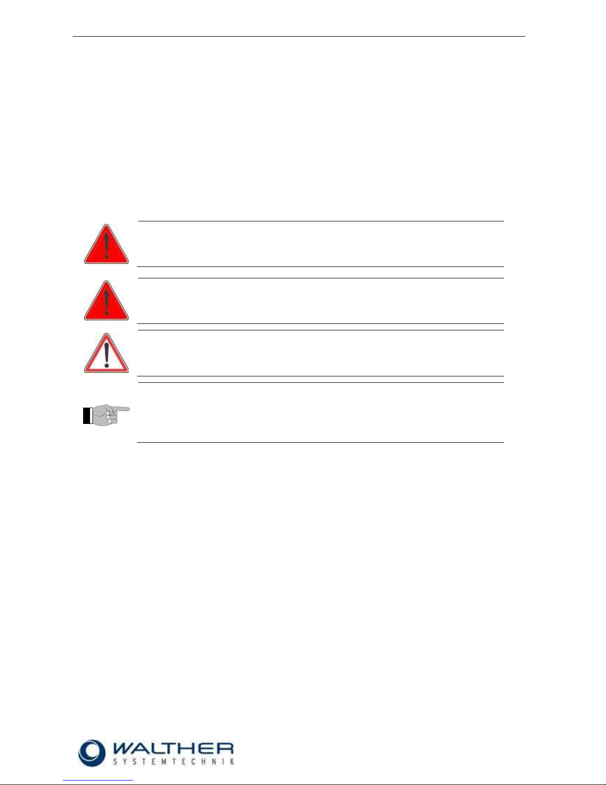
DANGER
Describes a potentially dangerous situation.
Death, grievous bodily harm or severe material damage WILL occur if the respective
measures of precaution have not been taken
WARNING
Describes a potentially dangerous situation.
Death, grievous bodily harm or severe material damage MAY occur if the respective
measures of precaution have not been taken.
CAUTION
Describes a potentially dangerous situation.
Slight injuries CAN occur if the respective measures of precaution have not been
taken. This signal word is also used to describe possible property damages.
IMPORTANT
Indicates tips for usage and other particularly useful information.
No dangerous situation.
2 Safety
2.1 General Information
The construction of the device is according to the latest technology and is absolutely reliable. The individual
components as well as the complete device are continuously checked by our quality management.
2.2 Dangers from Residual Energy
Please instruct the operating personnel on the respective measures to be taken against the occurrence of
mechanical, hydraulic, pneumatic and electric / electronic residual energies.
2.3 Warranty and Liability
According to the conditions laid down by the German Engineering Association (VDMA), Walther Systemtechnik GmbH has a guarantee of 12 months under normal European operating conditions on its own
parts (spare parts are excluded); or according to the conditions of the manufacturer.
This guarantee can only be granted by Walther Systemtechnik GmbH, if:
the user has thorough knowledge of the content of the assembly instructions;
the user follows the instructions and notes contained in the assembly instructions;
the user does not rebuild or make changes on parts of the device without prior consent of WST Sys-
temtechnik GmbH.
Page 6

Rev. 1.2
Assembly Instructions – Dosing Pen VMS-13-EH
Page 6 of 20
Walther Systemtechnik GmbH – D 76726 Germersheim
Telefon: +49 (0)7274-7022-0 Telefax: +49 (0)7274-7022-91
http://www.walther-2000.de – info@walther-2000.de
2.4 Correct Use
This device is a needle valve and will be used for processing materials which can be sprayed in continuous
or intermitting operation. Under no circumstances shall aggressive media such as acids, alkaline solutions,
detergents, chemicals or others be sprayed. If you are not sure, please contact the manufacturer if a certain
spray medium is suitable for this device.
2.5 Incorrect Use
Operating the device with insufficient knowledge about the operation, maintenance and care of the de-
vice.
Making changes, extensions or alterations on the device that may hamper its safety without the prior
consent of Walther Systemtechnik GmbH.
Operating the device with defective safety installations or not properly attached or malfunctioning safety
devices.
Using unsuitable materials.
Handling the device while energized
2.6 Qualification of Personnel
Only trained and instructed personnel may conduct work on the equipment.
The responsibilities of the personnel for assembly work, operation, repair work or maintenance work must be
clearly assigned to individuals!
Persons in training may work with the equipment only under supervision of an experienced person.
Personnel
Task
Instructed
Personnel
Personnel with Technical
Qualification
Specialist
Supervisor
Packaging, Transport
X
-
-
-
Commissioning
X
X
-
Operation
X
-
Troubleshooting, general
X
X
-
Troubleshooting
mechanical
-
X
-
-
Troubleshooting electrical
-
-
X
-
Setting up
-
X
-
-
Maintenance
-
X
-
-
Repair
-
X
X
-
Taking out of service,
Storage
-
X
X
-
Page 7

Rev. 1.2
Assembly Instructions – Dosing Pen VMS-13-EH
Page 7 of 20
Walther Systemtechnik GmbH – D 76726 Germersheim
Telefon: +49 (0)7274-7022-0 Telefax: +49 (0)7274-7022-91
http://www.walther-2000.de – info@walther-2000.de
3 Transport
3.1 Packaging
The type of packaging depends on the individual mode of shipping. If not separately contracted, the
packaging is in accordance with the rules and regulations of Walther Systemtechnik GmbH. This rule is in
accordance with the Federal Association for Packaging HPE.
3.2 Tasks before Transport
The following has to be done before transport:
Disconnect all power lines.
The actual transport of the incomplete device and its individual parts requires special care in order to prevent
damages from external forceful impact or careless on- and off-loading. Depending on the mode of
transportation, suitable transport and load securing has to be selected. The incomplete device will be aligned
and leveled by appropriate fastening elements.
4 Description of Function
The dosing pen VMS-13-EH is operated by a manual trigger/actuation. The spraying material will be supplied
from a pressure container or via a pump to the valve. The needle will be pulled back and releases the
material which is then discharged from the nozzle. The actual application image can be adjusted via the
nozzle or the nozzle extension, as well as the material pressure and the needle stroke settings.
4.1 Designated Purpose
CAUTION
The use of other media can cause functional failures, damages or even the destruction
of the device.
The VMS-13-EH dosing pen is a high-precision device which will be a long-term reliable tool if the following
notes are observed
The function of the needle is as follows:
Open by using the external controls and close after turn-off of external controls through the spring pressure.
Page 8

Rev. 1.2
Assembly Instructions – Dosing Pen VMS-13-EH
Page 8 of 20
Walther Systemtechnik GmbH – D 76726 Germersheim
Telefon: +49 (0)7274-7022-0 Telefax: +49 (0)7274-7022-91
http://www.walther-2000.de – info@walther-2000.de
4.2 Description and Operating Elements
4.3 Technical Data
General Data
Size (Length x Width x Height)
[mm]
ca.343 x 35 x 47
(actual length depends upon nozzle)
Energy Supply
Operating air pressure [bar]
3 - 6
Material pressure [bar]
max. 20 bar
Connection Manual Trigger
Control air [mm]
4
Material [mm]
6
Spray Head [mm]
G1/8“
Manual Actuation [Pin]
1 and 4
In the basic version, the WALTHER Dosing Pen comes without adapter nozzle. The adapter nozzle has to be
additionally selected and added! The WALTHER Dosing Pen will be delivered including an electric manual
actuation with accessories. The material connection is provided by a 6mm connector and control air by a
4mm PU hose.
4.4 Type Label
The type label has been etched into the casing. The serial number will be hammered into the type label.
Manual actuation
Valve body
Spray head
Electric manual
actuation with
accessories
Page 9

Rev. 1.2
Assembly Instructions – Dosing Pen VMS-13-EH
Page 9 of 20
Walther Systemtechnik GmbH – D 76726 Germersheim
Telefon: +49 (0)7274-7022-0 Telefax: +49 (0)7274-7022-91
http://www.walther-2000.de – info@walther-2000.de
5 Initial Start- up
The valves can be used in any position; the distance to the application area depends on the desired
application width.
5.1 Mounting and Installation
IMPORTANT
We recommend installing a maintenance unit to the control air.
Connect the WALTHER Dosing Pen VMS-13-EH to a pressure container or a pump via the material
connection (M6 IG); connect to the control air supply (min. 6 bar) via the hose connection (15). When using
an adapter nozzle, install the required attachment. Set material pressure at the container or the pump (max.
pressure: 20 bar). The material will now be released when you use the external controls.
5.2 Wiring Diagram – Manual Actuation Art. No.: 979297
Button connector to Pin1 and Pin4
Material connection „M“
Compressed air connection
„SL control air blue“
Connection
„manual actuation“
Page 10

Rev. 1.2
Assembly Instructions – Dosing Pen VMS-13-EH
Page 10 of 20
Walther Systemtechnik GmbH – D 76726 Germersheim
Telefon: +49 (0)7274-7022-0 Telefax: +49 (0)7274-7022-91
http://www.walther-2000.de – info@walther-2000.de
6 Operation
6.1 General Information
This device may only be operated if the safety-related equipment is permanently effective and not suspended during operation or altered in its intended effectiveness.
6.2 Operation Instructions / Operating Conditions
CAUTION
Never point the jet at people. The wearing of eye protection is strongly recommended.
The spraying process can create noise depending on the air and fluid pressures used.
Ear protection should be worn, if required.
WARNING
Danger caused by flammable, harmful fluid. Always follow the safety instructions on the
container or the safety data sheet for the fluid.
WARNING
Solvents and detergents from the chlorinated hydrocarbon group must not be used
because for example: 1,1,1 trichloromethane or methylene chloride can explosively
react with aluminum or galvanized parts.
The valves of the VMS-13-EH series generally operate with a control air pressure of 3 - 6 bar. Control air
pressure and material pressure should be closely correlated.
IMPORTANT
Accident prevention directions will be strictly followed when applying high material
pressures. Please strictly follow the following instructions when planning and
constructing application systems!
Each spraying valve must be equipped with its own pressure regulator for atomizing air.
In case several spraying valves are supplied by one and the same material pressure tank, these
valves must not spray simultaneously.
The supply route for the material between material pressure tank and spraying valve must not exceed
2 m.
If the pause time is a multiple of the spray time, the valve must be sprayed free in a separate location
or the spray valve should be operated several times to optimize the application.
After standstills of 15 min. and more, the valve must be sprayed free by pressing the switch 3 to 5
times.
For longer standstills, the material can remain in the valve, if it remains under pressure (no contact to
outside air).
6.3 Needle Stroke Settings
The quantity of the spray medium can be adjusted to the individual requirements by turning the adjustment
screw (13).
Function:
Right turn: Reducing quantity of the spray medium
Left turn: Increasing quantity of the spray medium
Page 11

Rev. 1.2
Assembly Instructions – Dosing Pen VMS-13-EH
Page 11 of 20
Walther Systemtechnik GmbH – D 76726 Germersheim
Telefon: +49 (0)7274-7022-0 Telefax: +49 (0)7274-7022-91
http://www.walther-2000.de – info@walther-2000.de
7 Taking out of Service
7.1 Short Interruption
A short interruption (15 min or more) has to be followed by a clear dosing/spraying.
IMPORTANT
Please follow the Operating Manual!
7.2 Long-term Interruption
The following has to be observed for a long-term interruption of the device/machine:
Depressurize material supply lines
Remove adapter nozzle (1) and clean with a special thinner and a soft cloth. Make sure that no cloth
fibers are left on the nozzle tip.
IMPORTANT
Please follow the maintenance guidelines!
7.3 Shutdown of Device
The following is important for a shutdown of the machine / device:
Clean dosing pen with a special thinner.
IMPORTANT
Please follow the maintenance guidelines!
8 Maintenance and Repair
8.1 General Information
The dosing pens of the VMS-13-EH series are high-quality precision devices which will not fail if treated
correctly and will operate almost maintenance-free. Always keep clean and observe minimum instructions to
maintain a long life of the valve. Always use clean and filtered material only. The control air must also be
clean and should be slightly oiled, if necessary. Maintenance also depends on the individual operating
conditions and the type of media used.
CAUTION
Before starting any maintenance or repair work, ensure that all air-operated tools are
depressurized and disconnected from the air supply.
Before opening the dosing pen it must be disconnected from the air and fluid supply.
Otherwise, ejected components can cause injuries.
We recommend oiling the dosing pen VMS-13-EH regularly at the mobile parts and greasing the threads –
particularly the nozzle thread- when exchanging nozzles and cleaning. Gasket (5) should be replaced after a
longer time of use.
Page 12

Rev. 1.2
Assembly Instructions – Dosing Pen VMS-13-EH
Page 12 of 20
Walther Systemtechnik GmbH – D 76726 Germersheim
Telefon: +49 (0)7274-7022-0 Telefax: +49 (0)7274-7022-91
http://www.walther-2000.de – info@walther-2000.de
8.2 Cleaning
IMPORTANT
Only use soft brushes for outside cleaning of the nozzle tips. Never use metal tools
with sharp edges.
Wash equipment thoroughly after use to remove residues and dirt, especially if needle (9) or adapter nozzle
(1) have to be exchanged. Use the thinner for sprayable media as detergent. A daily cleansing rinse will remove residues of the sprayable medium and clean almost all parts and channels which have been in contact
with the sprayable medium. Do not put the complete spray pistol into a thinner-bath as this will also remove
the lubricants.
8.3 Inserting new Gasket Elements
IMPORTANT
Gaskets and gasket holders can be damaged.
Do not use any sharp or pointed metallic implements for inserting the sealings!
8.4 Replacing Nozzle (1), TEFLON-sealing (5) and Needle (9)
Disconnect supply hoses (at M6 IG and 15) from device
Unscrew needle lock (12); extract spring (11)
Unscrew nozzle (1)
Use a soft tool to push back needle (9) through the needle sealing
Unscrew sealing screw (11) with slot screwdriver
You can easily exchange all elements now
Sequence for assembling:
Screw in sealing screw (11)
Screw in nozzle (1)
Insert needle (9) into the body through the sealing screw
Screw in needle lock (12)
8.5 Spare Parts
IMPORTANT
Only use original spare parts from the manufacturer!
Wrong or defective spare parts from other manufacturers can damage the device. If
other than original spare parts of the manufacturer will be used, all obligations from the
manufacturer or his sales partners, such as guarantees, service contracts etc will be
forfeited without further notice.
Page 13

Rev. 1.2
Assembly Instructions – Dosing Pen VMS-13-EH
Page 13 of 20
Walther Systemtechnik GmbH – D 76726 Germersheim
Telefon: +49 (0)7274-7022-0 Telefax: +49 (0)7274-7022-91
http://www.walther-2000.de – info@walther-2000.de
8.6 Customer Service / Support
Walther Systemtechnik GmbH
Hockenheimer Straße 3
D-76726 Germersheim
Germany
Phone ++49(0)7274-7022-0
Telefax ++49(0)7274-7022-91
Email info@walther-2000.de
Internet www.walther-2000.de
9 Troubleshooting
9.1 General Information
IMPORTANT
First check all supply lines for connection and serviceability.
In case of serious problems that cannot be resolved, please contact the Walther Systemtechnik GmbH
customer service.
9.2 Malfunctions:
Fault
Possible Cause
Action
Nozzle needle does
not open
Not enough control air supplied
Check if enough control air available (3 6 bar).
Leakages
Check if O-Rings are defective.
Needle is sticky within the needle sealing (9
/ 10).
Disassemble and clean.
Needle stroke is set too low.
Check if needle stroke is correctly set.
Nozzle is dripping
Needle (9) does not close properly because
nozzle (1) is loose
Fasten nozzle (1)
Page 14

Rev. 1.2
Assembly Instructions – Dosing Pen VMS-13-EH
Page 14 of 20
Walther Systemtechnik GmbH – D 76726 Germersheim
Telefon: +49 (0)7274-7022-0 Telefax: +49 (0)7274-7022-91
http://www.walther-2000.de – info@walther-2000.de
10 Appendix
10.1 Spare Part Drawing VMS-13-EH
10.1.1 Spare Part List for VMS-13-EH
Dwg No.
Art.-No.
Qty
Description
1
VMS-13
1
Walther-Dosing Pen
2
979297.00Z000
1
Electric Manual Actuation with accessories
Page 15

Rev. 1.2
Assembly Instructions – Dosing Pen VMS-13-EH
Page 15 of 20
Walther Systemtechnik GmbH – D 76726 Germersheim
Telefon: +49 (0)7274-7022-0 Telefax: +49 (0)7274-7022-91
http://www.walther-2000.de – info@walther-2000.de
10.2 Spare Part Drawing VMS-13
Page 16

Rev. 1.2
Assembly Instructions – Dosing Pen VMS-13-EH
Page 16 of 20
Walther Systemtechnik GmbH – D 76726 Germersheim
Telefon: +49 (0)7274-7022-0 Telefax: +49 (0)7274-7022-91
http://www.walther-2000.de – info@walther-2000.de
10.2.1 Spare Part List for VMS-13
Dwg No.
Art.-No.
Qty
Description
1 * 1
Nozzle (in the drawing: adapter nozzle 1.0 mm)
2
97640726
1
Gasket ring, Alu, ø10.8 x 6.5 x 1mm
3
97511406
1
Main body VMS-13, ø24 x 100mm, anodized
4
97910471
1
Hanging clamp, VMS-13 (optionally available)
5
97640004
1
Variseal 2.65 x 2.0 x 2.8
6
97640021
1
O-Ring 6.07 x 1.78 / Viton®
7
97810013
1
Sealing screw, diam. 11 x 21mm
8
97640026
1
O-Ring 2.90 x 1.78 / Viton®
9.1
97112293
1
Nozzle needle, KV, 0.2 – 1.5mm, 2 x 96.5mm
9.2
97710008
1
Piston, diam. 11.8 x 20.5mm
9.3
97610017
1
Threaded pin DIN 913 M3 x3
10
97640001
1
O-Ring 7.65 x 1.78 / Viton®
11
97820024
1
Pressure spring 1.2 x 21.5mm
12
97610567
1
Needle lock, normal, ø13.8 x 14mm, nickel-plated
13
97610558
1
Threaded pin DIN 913 M4 x25
14
97410006
1
Nut DIN 439 BM4
15
97221021
1
Plug-in nipple, brass, M5 - 4/3
* Article numbers can be found on the following pages.
IMPORTANT
Always indicate the inscribed serial numbers when ordering spare parts!
Page 17

Rev. 1.2
Assembly Instructions – Dosing Pen VMS-13-EH
Page 17 of 20
Walther Systemtechnik GmbH – D 76726 Germersheim
Telefon: +49 (0)7274-7022-0 Telefax: +49 (0)7274-7022-91
http://www.walther-2000.de – info@walther-2000.de
10.3 Spare Part Drawing – Manual Actuation 979297.00Z000
Page 18

Rev. 1.2
Assembly Instructions – Dosing Pen VMS-13-EH
Page 18 of 20
Walther Systemtechnik GmbH – D 76726 Germersheim
Telefon: +49 (0)7274-7022-0 Telefax: +49 (0)7274-7022-91
http://www.walther-2000.de – info@walther-2000.de
10.3.1 Spare Part List 979297.00Z000
Dwg No.
Art.-No.
Qty
Description
1
SMF-15-0056E002
1
Corrugated tube holder
2
PUN-4x0,75-SW
0,2m
Hose – polyurethane, black
3
PUN-4x0,75-BL
0,2m
Hose - polyurethane blue
4
MCM0074-054
1
Shrink hose 25,4 L=54mm
5
I-PACOF-17B-0800
1
Corrugated tube PACOF
6
I-BLNO-M207
1
Corrugated tube coupling, divisible
7
DIN913_M3X3
3
Threaded pin galvanized
8
979297
1
Finger switch
9.1
975165100657
1
Straight screw-in screw joint G1/4-6
10
97432241621
1
Straight connection 6-24162-1
11
97432230311
1
Screw-down holder for hose connector
12
97166080P
0,2m
High-pressure hose L800 NW4
13
970720411
1
Connector M6
14
252.22-ES
1
Bushing 1/4" VA
15
157B
1
2-wing hose clamp – hose outside 7-9mm
16
13968
1
Screw joint CRCN-M5-PK-4
17
136.0604
1
Straight connector
18
XSM-2426-20
2
Slide bearing
19
RV10GELRKÖED
1
Screw joint
10.4 Article Number for Nozzles
1
Adapter Nozzles „Standard“ (Length 31mm; IG G
1/8)
Article-No.
Description
97211587
Adapter Nozzle 0.3 mm
97211372
Adapter Nozzle 0.5 mm
97210984
Adapter Nozzle 1.0 mm
97211539
Adapter Nozzle 1.5 mm
1
Adapter Nozzles „Luer-Lock“ (M12 x 0.75),
complete
Article-No.
Description
97211915
Adapter Nozzle 0.2 mm
97211851
Adapter Nozzle 0.3 mm
97211997
Adapter Nozzle 0.5 mm
97211554
Adapter Nozzle 1.0 mm
97211909
Adapter Nozzle 1.5 mm
Page 19

Rev. 1.2
Assembly Instructions – Dosing Pen VMS-13-EH
Page 19 of 20
Walther Systemtechnik GmbH – D 76726 Germersheim
Telefon: +49 (0)7274-7022-0 Telefax: +49 (0)7274-7022-91
http://www.walther-2000.de – info@walther-2000.de
10.5 Accessories
Luer lock needles
97210152
Nozzle made of stainless steel, KV
97210603
Slit nozzle, rotary
979753
Adapter made of aluminium for foam
979756
Interchange parts made of foam
979752
Adapter made of aluminium for felt
979735
Interchange parts made of felt with plastic cap (size 15x6mm)
979735.01
Interchange parts made of felt with plastic cap (size 5x6mm)
979754.01
Interchange parts made of felt with plastic cap (size 3x3 mm)
979754.02
Interchange parts made of felt with plastic cap (size 5x5 mm)
979754.03
Interchange parts made of felt with plastic cap (size 10x6 mm)
252.33
Anschlussnippel G1/8 – G1/8
258.12
Dichtring G1/8
Page 20

Rev. 1.2
Assembly Instructions – Dosing Pen VMS-13-EH
Page 20 of 20
Walther Systemtechnik GmbH – D 76726 Germersheim
Telefon: +49 (0)7274-7022-0 Telefax: +49 (0)7274-7022-91
http://www.walther-2000.de – info@walther-2000.de
connection thread
97C00031
Brush made of horsehair 16 mm
1/8“
97C05008
Brush made of horsehair 28,5 mm
3/8“
979755
Felt pen
9713898
Brush made of horsehair 6,5 mm
1/8“
9713899
Brush made of horsehair 16 mm
1/8“
9712522
Brush made of perlon 6,5 mm to 70°C
1/8“
9712519
Brush made of perlon 16 mm to 70°C
1/8“
BT-SOFT.16
Brush tip needle BT16 Soft bristle
Luer lock
BT-SOFT.18
Brush tip needle BT18 Soft bristle
Luer lock
BT-SOFT.22
Brush tip needle BT22 Soft bristle
Luer lock
BT-STIFF.16
Brush tip needle BT16 Soft bristle
Luer lock
BT-STIFF.18
Brush tip needle BT18 Soft bristle
Luer lock
BT-STIFF.22
Brush tip needle BT22 Soft bristle
Luer lock
 Loading...