


S14
Table of contents
 Loading...
Operator’s Manual
Safety, Assembly, Operating, and Maintenance Instructions
Please Read and Save These Instructions
For Safety, Read All Safety and Operation
Instructions Prior to Operating Machine
Beginning S/N: 127922
Eective Date: 05.05.14
P/N 5000-28

Foreword
Thank you. . .for purchasing a Walker mower. Every effort has been made to provide you with the
most reliable mower on the market, and we are sure you will be among our many satised customers. If for any reason this product does not perform to your expectations, please contact your local
dealer. Every customer is important to us. Your satisfaction is our goal.
Please. . .read this manual thoroughly! This manual is to be used in conjunction with the engine
manufacturer’s manual for the specic engine on the mower model you have purchased. Before
you operate your new mower, please read this entire manual. Some of the information is crucial for
proper operation and maintenance of this mower - it will help protect your investment and ensure
that the mower performs to your satisfaction. Some of the information is important to your safety,
and must be read and understood to help prevent possible injury to the operator or others. If anything in this manual is confusing or hard to understand, please contact your local authorized dealer
or call our service department, at (970) 221-5614, for clarication before operating or servicing this
mower.
This manual covers Model S14 with the Subaru Robin, EX40 (14 HP) gasoline engine.
All shields and guards must be in place for the proper and safe operation of this machine.
Where they are shown removed in this manual, it is for illustration purposes only. Do not operate
this machine unless all shields and guards are in place.
Specications given are based on the latest information available at the time this manual was produced for a tractor with standard equipment. Optional equipment is available and may affect the
standard specications listed.
Walker Mfg. Co. is continually striving to improve the design and performance of its products. We
reserve the right to make changes in specications and design without thereby incurring any obligation relative to previously manufactured products.
Sincerely,
WALKER MANUF ACTURING COMP ANY
Bob Walker, President

Table of Contents
General Information ________________ 1
HIGHLIGHTED INFORMA TION _____________ 1
GLOSSARY ____________________________ 1
IDENTIFYING NUMBER LOCA TIONS ________ 1
ENGINE SERIAL NUMBER LOCA TION _______ 2
SERVICING OF ENGINE AND
DRIVETRAIN COMPONENTS ______________ 2
Specications ________________________ 3
ENGINE ________________________________ 3
ELECTRICAL SYSTEM ___________________ 3
TRANSMISSION _________________________ 3
BLADE DRIVE __________________________ 4
TIRE SIZE ______________________________ 4
TIRE PRESSURE ________________________ 4
DIMENSIONS (Tractor and Mower) _________ 5
GHS SYSTEM ___________________________ 5
MOWER DECK __________________________ 6
DRIVE BELTS ___________________________ 6
SEAT __________________________________ 6
FRAME/BODY CONSTRUCTION ___________ 6
Component Identication ___________ 7 Safety Instructions _________________ 10
BEFORE OPERA TING ___________________ 10
OPERATING ___________________________ 12
MAINTENANCE ________________________ 14
SAFETY , CONTROL, AND
INSTRUCTION DECALS _________________ 15
Assembly Instructions ______________ 18
SETUP INSTRUCTIONS __________________ 18
Tire Installation (T ractor) _______________ 18
Battery Service _______________________ 18
Wet Battery Service __________________ 18
Dry Battery Service ___________________ 18
Battery Charging _____________________ 19
Battery Installation ___________________ 19
Mower Deck Assembly _________________ 19
Deck Caster Wheels Installation _________ 19
Deck Discharge Chute Installation _______ 20
Deck Discharge Deector
Shield Installation ____________________ 20
PTO Shaft Guard Installation ___________ 20
Tilt-Up Roller Wheel Installation _________ 20
Mower Deck Installation on Tractor _______ 21
Deck Installation _____________________ 21
Deck Leveling _______________________ 22
PREOPERA TING CHECKLIST _____________ 23
Operating Instructions _____________ 25
CONTROL IDENTIFICA TION,
LOCA TION, AND FUNCTION _____________ 25
Ignition Switch _______________________ 25
Engine Choke ________________________ 25
Engine Throttle _______________________ 26
Forward Speed Control (FSC) ___________ 26
Front Body Latch Release ______________ 26
Steering Levers_______________________ 26
Blade Clutch (PTO) ____________________ 26
Parking Brake ________________________ 27
Transaxle Lockout Arms _______________ 27
Hourmeter ___________________________ 28
ST ARTING THE ENGINE _________________ 30
ADJUSTING GROUND
SPEED AND STEERING __________________ 30
ENGAGING THE BLADE DRIVE ___________ 32
STOPPING THE MACHINE _______________ 33
ADJUSTING CUTTING HEIGHT ____________ 34
TRANSAXLE LOCKOUTS ________________ 34
RECOMMENDA TIONS FOR MOWING ______ 35
RECOMMENDA TIONS FOR TIL T -UP DECK
OPERATION/TRANSPORT _______________ 37
GRASS HANDLING SYSTEM (GHS) ________ 38
General Information ___________________ 39
Clogging Checklist ____________________ 40
Using the Tilt-Up Deck _________________ 41
Using the GHS Catcher ________________ 41
Powerl
“Full” Signal Horn ____________________ 41
Cleaning the GHS Exhaust Screen _______ 42
Dumping the Catcher __________________ 42
T ailgate Dumping ____________________ 42
Using the Dump Bag __________________ 43
®
__________________________ 41

Table of Contents
Maintenance Instructions __________ 44
MAINTENANCE SCHEDULE CHART _______ 44
IMPORT ANT TIPS FOR CARE OF THE
SUBARU ENGINE _______________________ 45
Fuel System _________________________ 45
Starting/Stopping _____________________ 45
Cooling System ______________________ 45
Air Cleaner System ____________________ 45
Oil__________________________________ 45
LUBRICATION _________________________ 46
Engine Oil ___________________________ 46
Engine Break-In Oil ___________________ 46
Checking Engine Crankcase Oil Level ____ 46
Changing Engine Crankcase Oil _________ 47
Grease Fitting and Oil Point Lubrication __ 47
Mower Deck Gearbox Lubrication ________ 50
Mower Deck Spindle Lubrication ________ 50
Transaxle Lubrication _________________ 50
Transaxle Oil and Filter Change _________ 51
CLEANING ____________________________ 52
Engine Air Cleaner System _____________ 52
Donaldson Radialseal™ Air Cleaner ______ 52
Fuel Filter ___________________________ 54
Engine Cooling System ________________ 55
Cooling Air Intake Screen ______________ 55
Cylinder Head Cooling Fins ____________ 55
Grass Buildup in Mower Deck Housing ___ 56
GHS Blower __________________________ 56
GHS Exhaust Screen __________________ 56
Transaxle Housing ____________________ 57
CHECKING/SERVICING __________________ 57
Security of Air Filtration Components ____ 57
Battery ______________________________ 57
Electrolyte Level _____________________ 57
Cleaning the T erminals ________________ 58
Charging the Battery __________________ 58
Tire Pressure _________________________ 58
Wheel Nut T orque _____________________ 58
Sharpen Mower Blades ________________ 58
Drive Belts ___________________________ 60
Mower Deck Gearbox Oil Seals __________ 60
Spark Plug ___________________________ 60
Ignition _____________________________ 60
Fuel Lines and Clamps _________________ 60
Blade Brake Action ____________________ 60
Safety Switch System__________________ 61
Forward Speed Control Friction Lock _____ 61
REPLACING/REPAIRING _________________ 62
Drive Belts ___________________________ 62
Engine Belt _________________________ 63
PTO Drive Belt ______________________ 64
Ground Drive Belt ____________________ 65
Blade Overload Shear Bolts_____________ 66
PTO Shear Pin (If Equipped) ____________ 66
Mower Blades ________________________ 67
ADJUSTMENTS ________________________ 68
Transmission Control__________________ 68
Steering Lever Position Adjustment ______ 68
Steering Handles Adjustment ___________ 69
Neutral Position Adjustment ____________ 69
Full Forward Speed Adjustment _________ 71
Straight Tracking Adjustment ___________ 71
FSC Neutral Switch Adjustment _________ 71
Forward Speed Control
Friction Adjustment ___________________ 72
Blade Clutch (PTO) ____________________ 73
Clutch Engagement/Belt T ension ________ 73
Blade Brake Band Adjustment __________ 74
Tilt-Up Deck Adjustable Stop ____________ 75
GHS “Full” Signal Horn Adjustment ______ 76
Operator’s Notes _______________ 77
Warranty _____________________ 79

General Information
HIGHLIGHTED INFORMA TION
Walker Manufacturing recommends that any service
requiring special training or tools be performed by
an authorized Walker Mower dealer . There are several general practices to be aware of in the area of
safety. Most accidents associated with the operation or maintenance of a Walker Mower are caused
by disregarding basic safety precautions or specic
warnings. Such accidents, in most cases, can be
prevented by being aware of the dangers present.
Information of special importance has been highlighted in bold type in this manual. Refer to Safety
Instructions for the meanings of DANGER, WARN-
ING, CAUTION, IMPORTANT, and NOTE.
GLOSSARY
There are many terms that are either unique to this
equipment or that are used as acronyms. The following terms and their denitions will help while using this manual:
• DECK is the mowing attachment mounted on
the front of the tractor which includes the carrier
frame, deck housing, belt or gear drive components, and cutter blades.
• FORW ARD SPEED CONTROL (FSC) controls
the maximum forward speed of the tractor;
functioning as a cruise control.
• GRASS HANDLING SYSTEM (GHS
mowed material and deposits it in the catcher.
• GRASS-PAK
grass delivery spout (in the catcher) and activates the “full” signal horn when the grass
catcher is full.
®
SWITCH is mounted on the
®
) collects
• GROUND DRIVE refers to the dual transaxles
which drive the main wheels.
• LEFT HAND (LH) refers to the left-hand side of
the tractor when the operator is seated facing
forward in the tractor seat.
• POWER TAKE-OFF (PTO) transmits engine
power to run the cutter blades and GHS blower.
• POWERFIL
throughout the interior of the grass catcher by
an oscillating delivery spout.
®
spreads the mowed material
• RIGHT HAND (RH) refers to the right-hand side
of the tractor when the operator is seated facing
forward in the tractor seat.
• SIDE DISCHARGE (SD) discharges mowed
material from the right side of the mower deck.
• STEERING LEVERS steer the tractor by con-
trolling the two transaxles.
• TRACTOR is the prime mover , including the en-
gine, drivetrain, operator seat, and controls to
operate the mower.
• TRANSAXLE transmits and controls power
from the ground drive belt to the main drive
wheel.
• TRANSAXLE LOCKOUT ARMS release the
transaxles to permit freewheeling the tractor.
IDENTIFYING NUMBER LOCA TIONS
The tractor serial number plate is afxed to the tractor body just below the left rear corner of the seat.
The mower deck serial number plate is afxed
alongside the angle iron framing on the LH side of
the LH mower blade drive. Model and serial numbers are helpful when obtaining replacement parts
and maintenance assistance. For ready reference,
please record these numbers in the space provided.
Tractor Model No. ______________________
Tractor Serial No. ______________________
Deck Serial No. ______________________
Engine Model No. ______________________
Engine Serial No. ______________________
Date of Purchase ______________________
Fill In By Purchaser
1

General Information
Serial Number
Tractor Serial Number Location
SERVICING OF ENGINE AND DRIVETRAIN COMPONENTS
The detailed servicing and repair of the engine,
transaxles and gearboxes are not covered in this
manual. Only routine maintenance and general
service instructions are provided. For the service
of these components during the limited warranty
period, it is important to nd a local, authorized
servicing agent of the component manufacturer.
Any unauthorized work done on these components during the warranty period may void the
warranty. If you have any difculty nding an au-
thorized outlet or obtaining warranty service,
please contact our Service Department for assistance:
Serial Number
Mower Deck Serial Number Location
ENGINE SERIAL NUMBER LOCA TION
Refer to the engine manual that accompanies this
manual or the photo below for the location of the
engine serial number.
Serial Number
Walker Manufacturing Company
5925 E. Harmony Road
Fort Collins, CO 80528
1-970-221-5614
www.walkermowers.com
Service manuals are available for each of these
components from their respective manufacturers as
follows:
Subaru Engine Subaru Robin America Inc.
A division of Fuji
Industries, Ltd. Group
905 T elser Rd.
Lake Zurich, IL 60047
800-277-6246
www.subarupower.com
Transaxle Hydro-Gear
141 1 South Hamilton St.
Sullivan, IL 61951
877-728-7410
www.hydro-gear.com
Gearboxes (Deck) Peerless Gear
1555 South Jackson St.
Salem, IN 47167 USA
866-536-8310
www.peerlessgear.com
Engine Serial Number Location
2

Specications
MODEL S14
ENGINE
Manufacturer/Model Subaru Robin, EX40, 1 Cyl. (Air-Cooled)
Displacement cu. in. (cc) 24.65 (404)
Max. Power HP (kW) 14.0 (10.4) @ 3600 RPM
Governed RPM 3600
Max. Torque lb·ft (N·m) 19.9 (27.0) @ 2400 RPM
Idle RPM 1300
Spark Plug Type NGK BPR5ES
Spark Plug Gap in. (mm) .030 (0.75)
Crankcase Capacity qt (L) 1.35 (1.3)
Crankcase Lubricant
Fuel Tank Capacity gal (L) 1.9 (7.2)
Fuel
Cooling System Air Cooled
Air Cleaner Remote mounted Donaldson Radialseal
API SC/SD/SE/SF/SG/SH Grade Oil Only with 10W-30/10W-40
Viscosity or 40W Above 68° F (20° C) Only
Regular Grade Unleaded Gasoline (87 Octane Minimum,
10% Ethanol Maximum)
TM
(Walker P/N 5090-1 Primary/5090-3 Safety Filter)
ELECTRICAL SYSTEM
Battery 12 Volt, 300 CCA (Interstate SP-35)
Charging System Flywheel Alternator
Charging Output 13 Amp DC (Regulated)
System Polarity Negative Ground
Ignition Transistorized Electronic Magneto
Starter 12 Volt Electric Key and Solenoid Operated
Interlock Switches
Circuit Breaker Replaceable Fuse (20A)
TRANSMISSION
Manufacturer/Model Dual, Independent Hydro-Gear
Steering Hand Lever Control / Individual Wheel
Forward Speed Control
Service Brake Dynamic Braking through Transaxles
Parking Brake
Neutral Transmission Release by Manual Dump Valve
Ignition Lockout by Seat Switch, Transmission Neutral and Blade
Clutch
®
ZT3100 Integrated Transaxles
Precision Friction Lock Lever, Cruise Control, with
Neutral-Park Position
Internal Mechanical Cog Lock for each Transaxle
(Single Lever Control)
3

Specications
MODEL S14
TRANSMISSION (continued)
Final Drive Transaxle Direct to Drive Wheel
Transmission Fluid
Factory Service 20W-50 Multi-Viscosity Motor Oil (Minimum SL Grade Oil)
Transmission Oil Capacity oz (ml) 79 (2336)
Transmission Cooling Cooling Fan Mounted on Drive Pulley
Oil Filter Hydro-Gear
Ground Travel Speed
Forward MPH (km/h)
Reverse MPH (km/h)
BLADE DRIVE
PTO Shaft Sliding Spline Shaft with Two (2) High-Speed U-Joints
Blade Drive Clutch and Brake
®
P/N 52114 (Walker P/N 2026-6)
0-6.5 (0-10.5) Innitely Variable
0-5 (0-8) Innitely Variable
Manual Belt Tightener Clutch and Band Brake
[Stops Blades within Five (5) Seconds of Disengagement]
TIRE SIZE
Deck Caster 8 x 3.00-4 (Pneumatic 4-Ply, Optional Foamed Rubber)
Drive
Tailwheel 13 x 6.50-6 (Pneumatic 4-Ply)
TIRE PRESSURE PSI (KPA)
Deck Caster Wheel 20 (137)
Drive 15 (103)
Tailwheel 20 (137)
18 x 7.00-8 (Pneumatic 4-Ply, Standard)
18 x 8.50-10 (Pneumatic 4-Ply, Optional Low-Prole)
4

Specications
MODEL S14
DIMENSIONS (Tractor and Mower)
Length in. (cm)
Tractor Only 63.75 (162)
Tractor Wheel Base 43 (109)
Tractor with Tilted Deck
(Approximate)
Tractor with 36" Collection Deck
(DC36R-1)
Tractor with 42" Collection Deck
(DC42-1)
Width in. (cm)
Tractor Only (Outside Tire) 36 (91.5)
Tractor with 36" Collection Deck
(DC36R-1)
Tractor with 42" Collection Deck
(DC42-1)
Height in. (cm)
77 (196)
87 (221)
88.5 (225)
37.25 (95)
43.25 (110)
Tractor 46.75 (119)
Weight lb (kg)
Tractor Only 595 (270)
Tractor with 36" Collection Deck
(DC36R-1)
Tractor with 42" Collection Deck
(DC42-1)
GHS SYSTEM
Blower 12.5 in. Diameter, Three-Blade Paddle Wheel
Blower Brake
Max. Blower RPM 2900
Grass Catcher Capacity
gal / bu / L
Full Signal
Powerl
®
766 (347)
786 (356)
Band Brake [Works in Combination with PTO Clutch, Stops Blower
within Five (5) Seconds of PTO Disengagement]
65 / 7 / 246
Oscillating Vane Switch Mounted on Grass Delivery Spout Triggers
Horn Signal
Oscillating Delivery Spout Driven by 12 Volt Electric Gearmotor
Spreads Material throughout Interior of Catcher @ 35 Cycles/Min
5

Specications
MODEL S14
MOWER DECK
Recommended Cut Width
Cutting Height 1 to 4 in. (2.5 to 10 cm) in 1/2 in. (1 cm) Increments
Deck Suspension
DRIVE BELTS
Engine Walker P/N 5234-3
Ground Drive Walker P/N 5232-1
PTO Drive Walker P/N 5234-4
36 or 42 in. (91 or 107 cm)
(Collection, SD, Mulch)
Independent Torsion-Flex Frame with Caster Wheels and
Counterweight Springs
SEAT
FRAME/BODY CONSTRUCTION
Frame All Welded Unitized Steel Chassis
Body 14 Gauge Steel
Deck 11 Gauge Steel
GHS Catcher and Chutes Molded Cross-Linked Polyethylene (UV Stabilized)
Contour-Molded, with Nylon Backed Vinyl Cover and Integral
Foam Cushion
NOTE: The manufacturer reserves the right to make changes in specications shown herein at any time
without notice or obligation. The specications listed are for a standard conguration tractor, and may
change with the addition of optional equipment.
6

Component Identication
Grass Handling System
7.0 Bushel Catcher
NOTE: Control Identication
shown in Operating
Instructions section.
Tilt-Up Latch
Spring Clip
Anti-Scuff
Roller
Catcher Lift /
Dump Handle
Deck Support Arm
Deck Lift Handle
(Cutting Height Adjustment)
Deck Support Arm
Counterweight Spring
and Protective Cover
Deck Support Pins
and Height Adjustment
Hitch Pins
Tilt-Up
Deck Handle
Footrests
Tilt-Up Hook
(Not Visible)
Deck
Caster Wheels
Front View and Right Side View
7

Component Identication
Catcher Lift /
Dump Handle
Catcher Door
Gas Spring
(Not Visible)
Removable Grass
Catcher Screen
(Not Visible)
Catcher Door
Catcher
Air Exhaust
Catcher
Door Handle
Anti-Scuff
Roller
Left Hand
Drive Wheel
8
Mufer
Tailpipe
Rotating Engine
Screen
Rear View and Left Side View
T ailwheel Fork
and Wheel

Component Identication
Fuel T ank
Fuel T ank
Cap
Battery Cable
BatteryNegative (-)
Positive (+)
Battery Cable
Air Intake Hose
Donaldson
Air Cleaner
Tailpipe
Air Cleaner
Cover
Mufer
Heat Shield
PTO Clutch
Lever
RH Transaxle
Lockout Arm
RH Transaxle
Parking Brake
Lever
GHS Blower
LH Transaxle
Lockout Arm
LH Transaxle
Neutral Safety
Switch
T op View (Body Raised)
9

Safety Instructions - Before Operating
Pay particular attention to any information labeled
DANGER, WARNING, CAUTION, IMPORTANT,
and NOTE in this manual.
When you see the Safety Alert Symbol ( ), read,
understand, and follow the instructions. Fail ure to
comply with safety instructions may result in personal injury .
The seriousness or degree of importance of each
type of information is dened as follows:
DANGER
An IMMEDIATE hazard that WILL result in
severe personal injury or DEATH, if warning is ignored and proper safety precautions are not taken.
WARNING
A POTENTIAL hazard that COULD result in
severe personal injury or DEATH, if warning is ignored and proper safety precautions are not taken.
Walker Manufacturing cannot predict every potentially dangerous situation. Therefore, items labeled
as such in this manual do not cover all conceivable
situations. Any person using procedures, tools, or
control techniques not recommended by Walker
Manufacturing must take full responsibility for safety .
The Walker Rider Lawnmower has been designed
with many safety features to protect the operator from
personal harm or injury . However , it is necessary for
the operator to use safe operating procedures at all
times. Failure to follow safety instructions con-
tained in this manual may result in personal injury or damage to equipment or property .
If you have any questions concerning setup, operation, maintenance, or safety, please contact your
authorized Walker Mower dealer or call Walker
Manufacturing Company at (970) 221-5614.
BEFORE OPERA TING
1. Read and understand the contents of this
Operator’s Manual before starting and operating the machine. Become thoroughly famil-
iar with all machine controls and how to stop the
machine and disengage the controls quickly.
Replacement Operator’s Manuals are available
by sending the Model and Serial Number to:
Walker Manufacturing Company
5925 East Harmony Road
Fort Collins, CO 80528
10
CAUTION
Possible hazards or unsafe practices that
MAY result in MODERATE personal injury
or property damage, or machine damage, if
warning is ignored and proper safety precautions are not taken.
IMPORTANT: Identies mechanical information
demanding special attention, since it deals with the
possibility of damaging a part or parts of the machine.
NOTE: Identies information worthy of special at-
tention.
2. Never allow children to operate rider mower.
Do not allow adults to operate without proper
instruction.
3. Clear the area to be mowed of any foreign
objects which may be picked up and thrown by
cutter blades. Pick up all sticks, stones, wire,
and any other debris.
4. Keep everyone, especially children and pets, a
safe distance away from the area being mowed.
Do not mow with bystanders in the area.
5. Do not operate the machine barefoot or wearing
sandals, sneakers, tennis shoes, or similar
lightweight footwear. Wear substantial pro-
tective footwear.

Safety Instructions - Before Operating
6. Do not wear loose tting clothing that could get
caught in moving parts. Do not operate this machine while wearing shorts; always wear ade-
quate protective clothing, including long
pants. Wearing safety glasses, safety shoes,
and a helmet is advisable and required by some
local ordinances and insurance regulations.
7. Prolonged exposure to loud noise can cause
impairment or loss of hearing. Operator hear-
ing protection is recommended; particularly
for continuous operation of the GHS Model due
to blower noise level. Wear a suitable hearing
protective device, such as earmuffs or earplugs.
8. Keep all protective shields and safety de-
vices in place. If a protective shield, safety
device, or decal is damaged, unusable, or missing, repair or replace it before operating the
machine.
9. Be sure interlock switches are functioning
correctly, so the engine cannot be started unless the Forward Speed Control lever is in the
NEUTRAL-PARK position, and the PTO clutch
is in the DISENGAGED position. Also, the engine should stop if the operator lifts off the seat
with either the Forward Speed Control (FSC)
out of the NEUTRAL-PARK position or the PTO
clutch in the ENGAGED position.
12. The electrical system battery contains sulfuric
acid. Avoid any contact with skin, eyes, and
clothing. Keep the battery and acid out of reach
of children.
WARNING
The engine exhaust from this product
contains chemicals known to the State of
California to cause cancer, birth defects or
other reproductive harm.
10. Handle gasoline with care. Gasoline is highly
ammable and its vapors are explosive:
a. Use an approved fuel container.
b. Never add fuel to a running engine or hot
engine (allow hot engine to cool several minutes).
c. Keep matches, cigarettes, cigars, pipes,
open ames, or sparks away from the fuel
tank and fuel container.
d. Always ll the fuel tank outdoors using care.
Fill to about one inch from the top of the tank.
Use a funnel or spout to prevent spilling.
e. Replace the machine fuel cap and container
cap securely and clean up any spilled fuel
before starting the engine.
11. Never attempt to make any adjustments
while the engine is running, except where
specically instructed to do so.
11
Safety Instructions - Operating
1. Operate the mower only in daylight or in
good articial light with good visibility of the area
being mowed.
2. Sit on the seat when starting the engine and
operating the machine. Keep feet on the deck
footrests at all times when the tractor is moving
and/or mower blades are operating. Never op-
erate the tractor without a deck or implement installed.
3. For a beginning operator, learn to steer (maneuver) the tractor with a slow engine speed
before attempting any mowing oper ation.
Be aware that, with the front mounted mower
conguration, the back of the tractor swings to
the outside during turns.
DANGER
Do not mow around overhanging tree
branches or bushes at the same height as
the operator’s torso and head where inadvertent contact may cause injury.
7. Do not operate machine if the operator presence safety switch system is not working.
Verify proper operation by having the operator
lift off the seat with the engine running and moving two controls, one at a time; (1) Move the
FSC lever out of the NEUTRAL-PARK position,
and (2) Engage the PTO Clutch. Moving either
control should stop the engine immediately.
8. Do not run the engine in a conned area
without adequate ventilation. Exhaust fumes
are hazardous and can be deadly.
9. Do not carry passengers - maximum seating
capacity is one (1) person.
10. Watch for holes, rocks, and roots in the terrain
and for other hidden hazards. When mowing
tall grass, mow higher than desired to expose
any hidden obstacles. Then, clean the area and
mow to the desired height.
11. Avoid sudden starts or stops. Before back-
ing the machine up, look to the rear to be sure
no one is behind the machine. Watch carefully
for trafc when crossing or working near roadways.
4. Remember, for an emergency stop, the forward
motion of the tractor can always be stopped by
pulling the Forward Speed Control (FSC) into
the NEUTRAL-PARK position.
5. If either of the transmission drive belts break
during slope operation, the machine will free-
wheel down the slope. To maintain control,
immediately (1) Release the steering levers and
simultaneously (2) Move the FSC to the NEU-
TRAL-PARK position. When the machine is
stopped or moving slowly, engage the parking
brake.
NOTE: The emergency stop procedure is exactly t he sa me procedure used to normally stop
and park the machine.
6. Disengage the blade clutch and put the FSC in
the NEUTRAL-PARK position before starting
the engine (an ignition interlock switch normally
prevents starting of the machine if these controls are in the OPERATING position).
12. When moving forward, do not suddenly put the
tractor in reverse by rapidly pulling on the steering levers, especially when going downhill, as
this can lift the tractor tail wheel off the ground
and set up a bucking motion due to operator
overcontrol. If bucking does occur, immediately
stop the bucking action by pulling the Forward
Speed Control (FSC) lever into the NEUTRAL-
PARK position.
13. Disengage the blade drive when transporting
the machine across drives, sidewalks, etc. Nev-
er raise the mower deck while blades are
rotating.
DANGER
Do not mow or drive the tractor within
5 feet (1.5 meters) of an embankment or retaining wall with drop off.
12
Safety Instructions - Operating
14. The maximum recommended slope operating angle is 15 degrees or 26% grade. When
operating the machine on a slope, reduce speed
and use caution to start, stop, and maneuver.
To prevent tipping or loss of control of the machine, avoid sharp turns or sudden changes in
direction. Do not operate the machine on a
slope greater than 15 degrees.
15. Never adjust cutting height with the engine
running. Before adjusting cutting height or
servicing, disengage the blade clutch (PTO),
stop the engine, and remove the ignition key.
Wait for all movement to stop before getting off
the seat.
NOTE: A blade/blower brake should normally
stop drive line rotation within ve (5) seconds of
disengaging the PTO clutch.
16. For side discharge mower decks, do not oper-
ate with the grass deector shield removed.
Keep the deector in the lowest possible position.
17. When using the tilt-up deck, observe the fol-
lowing:
a. Do not move tractor with deck in tilt-up
position.
b. Never tilt body forward with deck in tilt-up
position.
18. Do not operate the machine with the grass
catcher in the DUMP position or with the
back door OPEN. Dangerous projectiles may
be thrown out of the discharge chute or the back
of the grass catcher.
19. Use care when closing the grass catcher
door. Keep ngers and hands away from the
hinge and pinch points when the door is being
closed. Also, keep ngers and hands clear of
the door frame. The door is held closed with
springs and the door may slam shut with considerable force.
20. In case of a clogged or plugged mower deck
or GHS catching system:
a. Disengage the blade clutch (PTO) and turn
the engine off before leaving the seat.
b. LOOK to make sure blade drive shaft and
blower drive pulley movement has stopped
before trying to unclog the system.
c. Disconnect the spark plug wire.
d. Never place hands under the deck or in the
GHS blower - use a stick or similar tool to
remove clogged material.
21. If the cutting blades strike a solid object or the
machine begins to vibrate abnormally,
immediately disengage the blade clutch
(PTO), stop the engine, and wait for all
moving parts to stop. To prevent accidental
starting, disconnect the spark plug wire.
Thoroughly inspect the mower and repair any
damage before restarting the engine and
operating the mower. Make sure cutter blades
are in good condition and blade nuts are torqued
to 60 lb·ft (81 N·m) for gear driven decks, and
blade bolts torqued to 70 lb·ft (90 N·m) for belt
driven decks.
22. Do not touch the engine or mufer while the
engine is running or immediately after stopping the engine. These areas may be hot
enough to cause serious burns.
23. When leaving the machine unattended, disen-
gage the blade clutch (PTO), stop the engine, and remove the key.
CAUTION
Use leg muscles and rm footing when lifting the catcher to dump; avoid bending at
the waist and using back muscles in order
to prevent back injury.
13

Safety Instructions - Maintenance
1. To prevent accidental starting of the engine
when servicing or adjusting the machine, remove the key from the ignition switch and disconnect the spark plug wire.
2. To reduce re hazards, keep the engine free
of grass, leaves, excessive grease, and dirt.
3. Keep all nuts, bolts, and screws tight to ensure
the machine is in a safe, working condition.
Check the blade mounting nuts frequently , making sure they are tight.
4. Perform only maintenance instructions de-
scribed in this manual. Unauthorized mainte-
nance operations or machine modications
may result in unsafe operating conditions.
5. If the engine must be running to perform a maintenance adjustment, keep hands, feet, and
clothing away from moving parts. Do not wear
jewelry or loose clothing.
6. Always use the proper engine service
manual when working on the engine.
Unauthorized maintenance operations or
modications to the engine may result in unsafe
operating conditions.
11. Use care when charging the battery or per-
forming maintenance on the battery and electrical system:
a. Make sure the battery charger is unplugged
before connecting or disconnecting cables
to the battery.
b. Charge the battery in a well-ventilated
space, so gases produced while charging
can dissipate. Make sure the battery vents
in the caps are open.
c. Keep sparks, ames, and smoking materi-
als away from the battery at all times. To
avoid sparks, use care when removing battery cables from posts.
d. Disconnect both battery cables before un-
plugging any wiring connectors or making
repairs on the electrical system.
IMPORTANT: Keep all applicable manuals immediately accessible to anyone who may operate or service this machine.
7. Altering the equipment or engine in any manner
which adversely affects its operation, performance, durability, or use will VOID the war-
ranty and may cause hazardous conditions.
8. Never attempt to disconnect any safety devices
or defeat the purpose of these safety devices.
9. Do not change the engine governor settings or
overspeed the engine. The governor has been
factory-set for maximum-safe engine operating
speed.
10. Use genuine factory replacement parts.
Sub stitute parts may result in product malfunction and possible injury to the operator and/or
others.
14
Safety Instructions
SAFETY, CONTROL, AND INSTRUCTION DECALS
Safety , Control, and Instruction Decals are installed on the machine;
if any are missing, illegible, or damaged, a replacement should be ordered and installed before
putting the machine into operation. The Decal Part Number is listed below and in the Parts Manual.
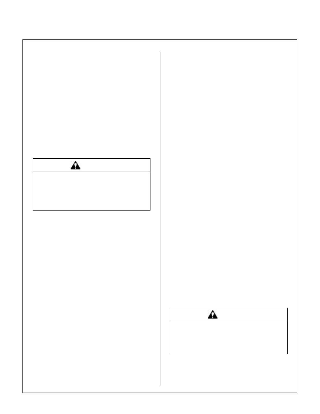
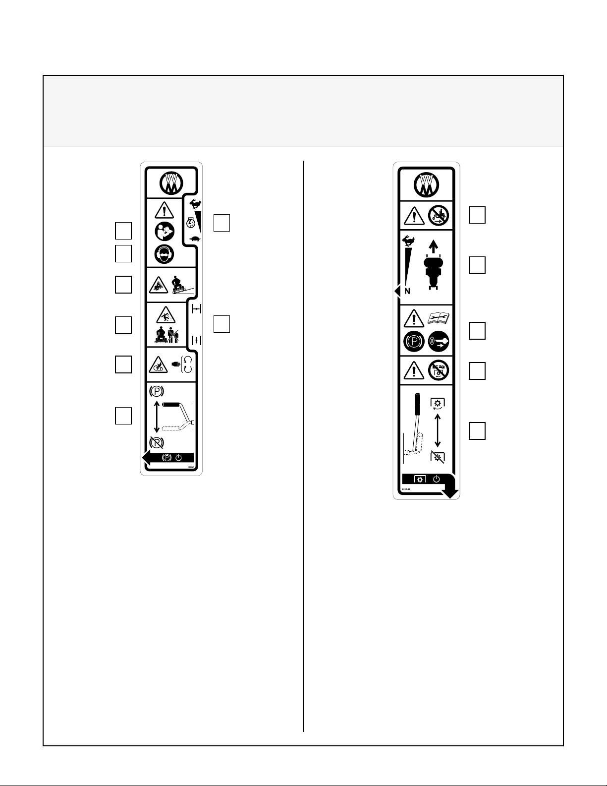
1.
2.
8600-4
Location: Adjacent to Blower Discharge
Chute through Body
Part Number: 8600-4
1. W arning - rotating impeller is a cutting/dismem-
berment hazard to ngers and hands.
• Never reach down into the blower discharge
chute.
2. Warning - thrown object hazard.
• Never engage the PTO with grass catcher
raised.
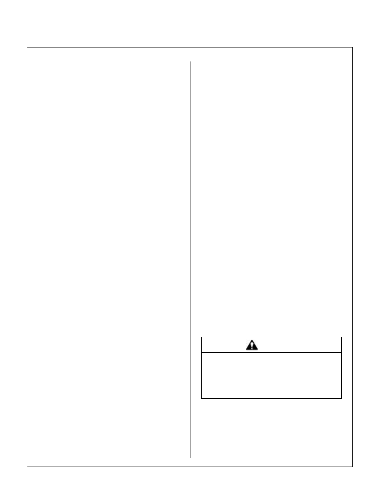
1.
8600 -12
Location: T op of Fuel T ank
Part Number: 8600-12
1. Warning – carbon monoxide (CO) poisoning
hazard.
• CO emitted by a running engine can be deadly .
• Do not operate indoors or in other enclosed
areas.
60 lb·ft (81 N·m)
1.
8600-9
Location: Gearbox Cover
(Gear Drive Decks Only)
Part Number: 8600-9
1. Tighten blade nuts on gear driven decks to
60 lb·ft (81 N·m).
Location: Rear of Grass Catcher Exhaust Screen
Part Number: 5869
1.
Location: Catcher Door Hinge Bar,
LH and RH Sides
Part Number: 8600-10
1. Caution - Pinch point.
• Keep all body parts clear when closing grass
catcher door.
9804-1
1.
Location: Chassis Member Behind Transaxles
Part Number: 9804-1
1. Neutral Lock
• Lift and move into slot to unlock transmission and allow machine to freewheel.
15
Safety Instructions
SAFETY, CONTROL, AND INSTRUCTION DECALS
Safety , Control, and Instruction Decals are installed on the machine;
if any are missing, illegible, or damaged, a replacement should be ordered and installed before
putting the machine into operation. The Decal Part Number is listed below and in the Parts Manual.
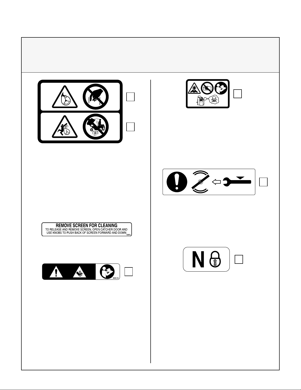
8600-28
Location: Each End of Mower Deck
Part Number: 8600-28
1. Warning – thrown object hazard.
• Keep bystanders away from the machine
when operating.
• Clear lawn of debris before operating.
• Keep any discharge deector in place and in
the lowest position.
2. Warning – rotating mower blades are a cutting/
dismemberment hazard to hands and feet.
• Keep all body parts away from rotating mower blades.
• Do not step on end of deck.
8600-14
Location: Deck Carrier Frame
Part Number: 8600-14
1.
2.
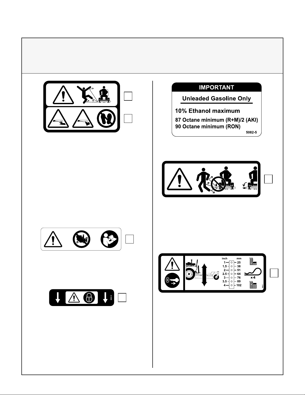
1.
Location: T op of Fuel T ank
Part Number: 5082-5
1.
5848-2
Location: Deck Discharge Shield
(SD Decks Only)
Part Number: 5848-2
1. Warning – thrown object hazard.
• Always keep the discharge shield in the lowest position when operating.
• Do not remove the discharge shield.
16
1. Warning – do not operate the machine with the
deck tilted up.
1.
Location: Deck Carrier Frame
Part Number: 8600-15
1. Warning – lock deck tilt-up hinge before operating the machine.
1.
Location: Deck Gearbox Cover
Part Number: 8600-7
1. Warning - stop engine and remove ignition key
before adjusting deck cutting height.
Safety Instructions
SAFETY, CONTROL, AND INSTRUCTION DECALS
Safety , Control, and Instruction Decals are installed on the machine;
if any are missing, illegible, or damaged, a replacement should be ordered and installed before
putting the machine into operation. The Decal Part Number is listed below and in the Parts Manual.
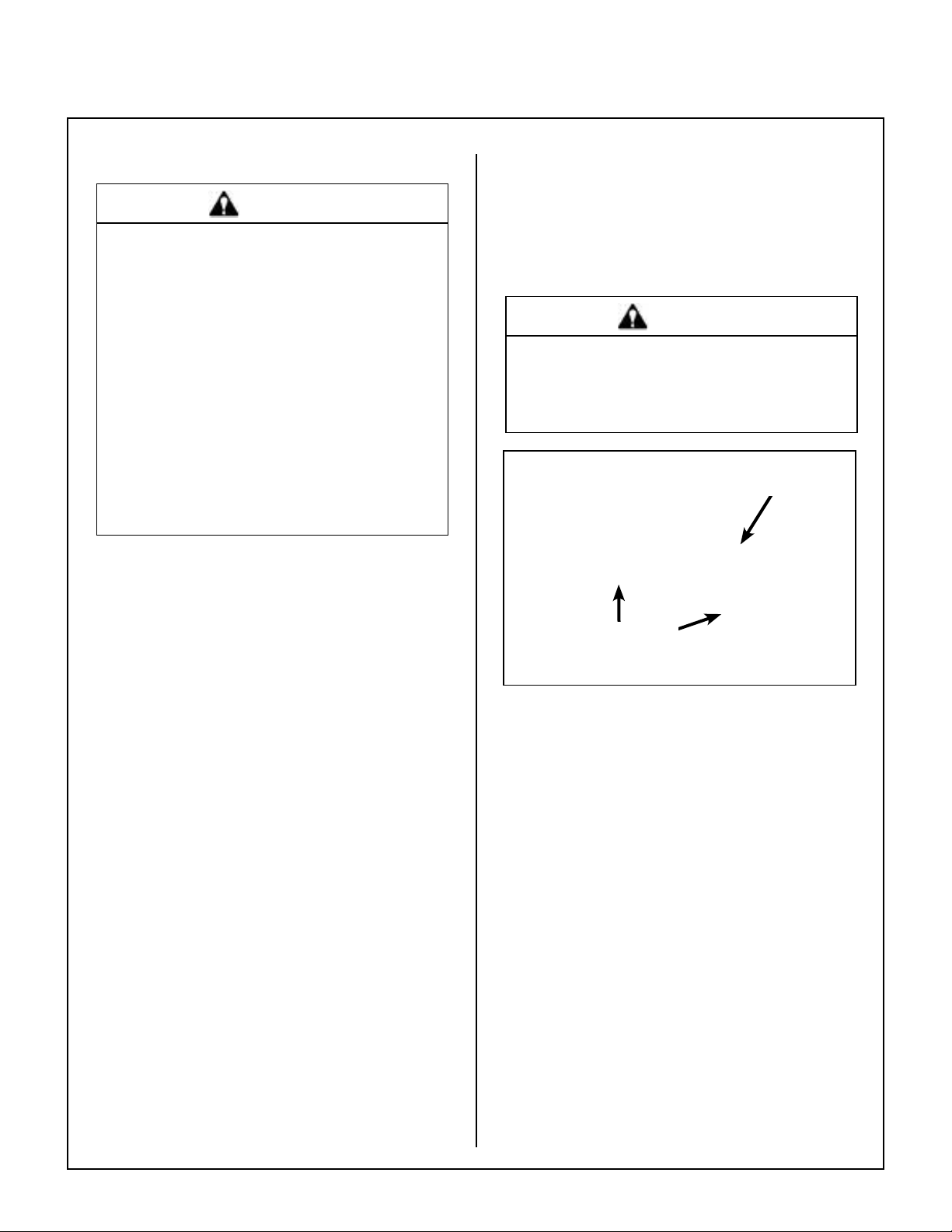
2.
3.
4.
5.
7.
8.
Location: LH Fender
Part Number: 8600-27
1. Throttle
2. Warning – read Operator’s Manual before operating the machine.
3. Warning – wear eye and ear protection when operating the machine.
4. Warning – roll-over hazard.
• Do not operate on slopes greater than 15
degrees.
5. Warning – thrown object hazard.
• Keep bystanders away from the machine
when operating.
6. Choke
7. Warning – entanglement hazard.
• Keep all guards in place while engine is running.
8. Parking brake
• Move lever forward to engage Parking
Brake; back to disengage.
<15°
1.
6.
1.
2.
1. 2.
Location: RH Fender
Part Number: 8600-26
1. Warning – do not operate the machine without a
deck or other implement attached.
2. Forward Speed Control
• Move lever forward to increase speed; back
to stop.
3. Warning – read Operator’s Manual before servicing or performing maintenance.
• Engage parking brake.
• Remove ignition key.
4. Warning – do not engage PTO clutch with PTO
shaft disconnected.
5. PTO Clutch Lever
• Move lever forward to engage PTO clutch;
back to disengage.
3.
4.
5.
17

Assembly Instructions
SETUP INSTRUCTIONS
Walker Mowers are shipped partially assembled to
our distribution network, and are typically assembled by the selling dealer. For any additional assembly besides the following, contact your Walker
dealer.
Tire Installation (T ractor)
• Install the drive tires using the eight (8) lug bolts
that are supplied with the owner’s packet of
materials. Bolts are torqued to 75 to 85 lb·ft
(102 to 115 N·m).
• Check and adjust the ination of the tires. The
tire ination recommendations are:
Drive = 15 PSI (103 kPa)
Tailwheel = 20 PSI (137 kPa)
Battery Service
Raise front mower body up for battery access (refer
to Front Body Latch Release in Operating Instruc-
tions). Check the battery for electrolyte level and
charge. The electrolyte level should be at the bottom of the vent wells [1/4 to 1/2 in. (6 to 13 mm)
above plates]. If the specic gravity is less than
1.225, the battery needs charging. If the battery has
been shipped dry, or is wet but needs service, refer
to the following instructions.
IMPORTANT: Make sure battery is securely mounted in the frame. A loose battery may cause damage
to the case resulting in acid leakage and severe damage to the machine. A hazard may be created by
damage to critical working parts and safety systems.
Wet Battery Service
If the battery has been shipped wet, but the electrolyte level is low or the battery needs to be charged
then:
Dry Battery Service
DANGER
Activating a battery can be dangerous.
The battery should be taken to a reliable
service station, battery store, or power
equipment dealer where a trained technician can activate the battery safely. DO
NOT attempt to activate the battery unless
you are experienced in battery service
work. The following activation and charging instructions are provided for use by a
trained battery technician.
DANGER
Battery electrolyte is a poisonous and corrosive sulfuric acid solution.
• Avoid spillage and contact with skin,
eyes, and clothing - causes severe burns.
• To prevent accidents, wear safety gog-
gles and rubber gloves when working with
electrolyte.
• Neutralize acid spills with baking soda
and water solution.
To ll (activate) battery with electrolyte (if battery has
been shipped dry):
1. Remove the battery protector plate, disconnect
the battery cables and lift the battery out of the
tray.
IMPORTANT: Battery must be removed from
the mower before lling with electrolyte.
18
1. Fill each battery cell with distilled water to the
bottom of the vent wells.
2. Charge battery. Refer to Battery Charging in
this section.
IMPORTANT: Obtain and use only battery
grade sulfuric acid electrolyte with a 1.265 specic gravity to activate the battery. DO NOT use
water or any other liquid during initial activation.
2. Remove the ller caps and carefully ll each cell
until the electrolyte is just above the plates.
3. After the battery is lled with electrolyte, replace
the ller caps and charge the battery. Refer to
Battery Charging.
Assembly Instructions
Battery Charging
DANGER
BA TTERIES PRODUCE EXPLOSIVE GASES
• Charge the battery in a well-ventilated
area, so that gases produced while charging can dissipate.
• Keep sparks, ames, and smoking mate-
rials away from the battery at all times.
• Make sure the battery cap vents are open
after the battery is lled with acid (check
manifold vent on each cap).
• Make sure the battery charger is un-
plugged before connecting or disconnecting cables to the battery.
1. Charge the battery at 15 amps for 10 minutes.
DO NOT exceed 20 amps maximum recom-
mended charging rate. Charge until specic
gravity is at least 1.250. Total charging time
should not exceed one (1) hour.
2. After charging the battery, adjust the electrolyte
level to the bottom of the vent wells [1/4 to 1/2 in.
(6 to 13 mm) above the plates].
Install the battery in the mower as shown in Battery
Installation photo. Connect the positive (+) rst and
then the negative (-) cable to the proper battery terminal [red cable and boot connects to the Posi-
tive (+) terminal]. Slide the rubber boot up and over
the battery post, making sure it covers the post completely to prevent an electrical short.
WARNING
Make sure the battery cap vents are open.
Improper venting of the battery COULD
cause a battery explosion.
(+) Battery Cable
Connection
Battery Clamp
Secured by
Wing Nut(s)
Battery Installation
IMPORTANT: DO NOT overll the battery.
Electrolyte will overow through the vented caps
onto parts of the machine and WILL result in severe corrosion.
3. Install battery.
Battery Installation
IMPORTANT: Make sure battery is securely mounted in the frame. A loose battery may cause damage
to the case resulting in acid leakage and severe
damage to the machine. A hazard may be created
by damage to critical working parts and safety systems.
Mower Deck Assembly
Deck Caster Wheels Installation
1. Remove the bolt, nut, axle spacer tube, and
spacer washers from each deck caster wheel
fork.
NOTE: Spacer washers are used only when
the optional semi-pneumatic deck wheels are
installed.
2. Fit the axle spacer tube through the wheel hub,
position the spacer washer on each side of the
hub (if used), and t the assembly into the wheel
fork.
3. Insert the 3/8-16 x 4-1/2 in. bolt through the
wheel fork with the bolt head to the outside and
install the 3/8-16 in. Keps nut.
19
Assembly Instructions
4. Tighten the bolt and nut until the axle spacer
tube bottoms against the inside of the wheel
fork (will not turn) while the wheel and spacer
washers (if used) spin freely without binding.
Axle Spacer
Tube
Spacer Washer
Axle Bolt
Deck Caster Wheel Installation
NOTE: If semi-pneumatic wheels are installed,
make sure the spacer washers t over the spacer tube and are not caught between the fork and
the end of the tube. The washers should move
freely on the axle spacer tube.
Deck Discharge Deector Shield Installation
(Side Discharge Models Only)
Attach the side discharge deector shield using two
(2) 3/8-16 x 1-1/4 in. bolts, 3/8-16 ESNA nuts, and
3/8 in. wave spring washers. The wave washers t
between the two hinging surfaces. Tighten the nuts
until the shield moves freely but is not loose.
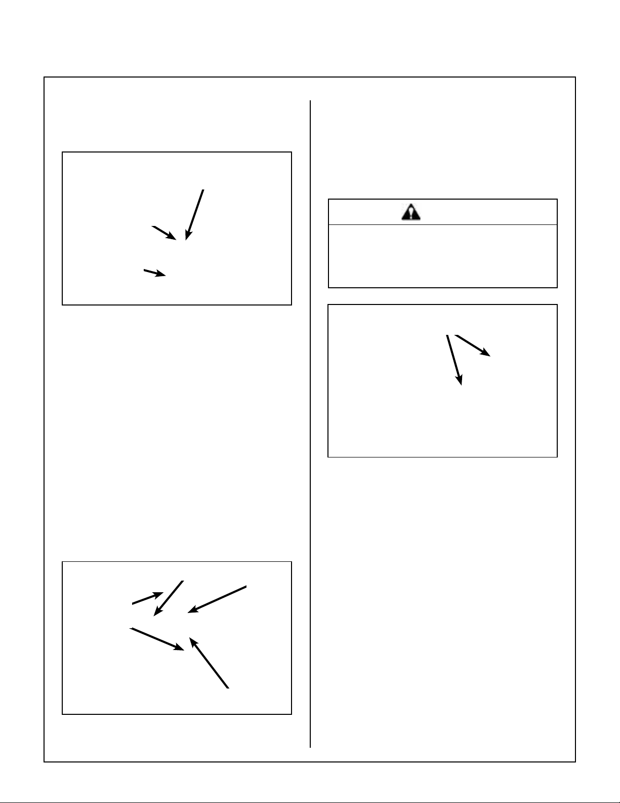
WARNING
DO NOT operate the machine without the
grass deector shield attached and in the
lowest possible position.
Attach Shield
5. Grease the caster wheel bearings and caster
pivot bearings - one grease tting for each
wheel and each pivot.
Deck Discharge Chute Installation (GHS Rear Discharge Models Only)
Mount the discharge chute hinge on top of the deck
discharge opening using two (2) 1/4-20 x 1/2 in. button head socket cap screws and 1/4-20 ESNA nuts.
Position the screws with the heads inside the chute
and the nuts on the outside. Attach spring for tilt-up
action from chute to bracket on deck.
Attach Guard
Carrier Frame
Tube Sockets
Nut on T op
Attach
Chute
Discharge Shield Installation
on Side Discharge Deck
PTO Shaft Guard Installation
Position the shaft guard as shown and mount with
two (2) 1/4-20 x 1/2 in. bolts.
Tilt-Up Roller Wheel Installation
Mount the two (2) tilt-up roller wheels on the brackets on the rear skirt of the deck housing using the
P/N 8490 axle bolt, 3/8 in. wave spring washer and
3/8-16 in. Whiz locknut. Tighten the axle bolt until
the wheel rolls freely, but is not loose.
20
Discharge Chute and PTO Shaft Guard
Installation on Rear Discharge Deck
Assembly Instructions
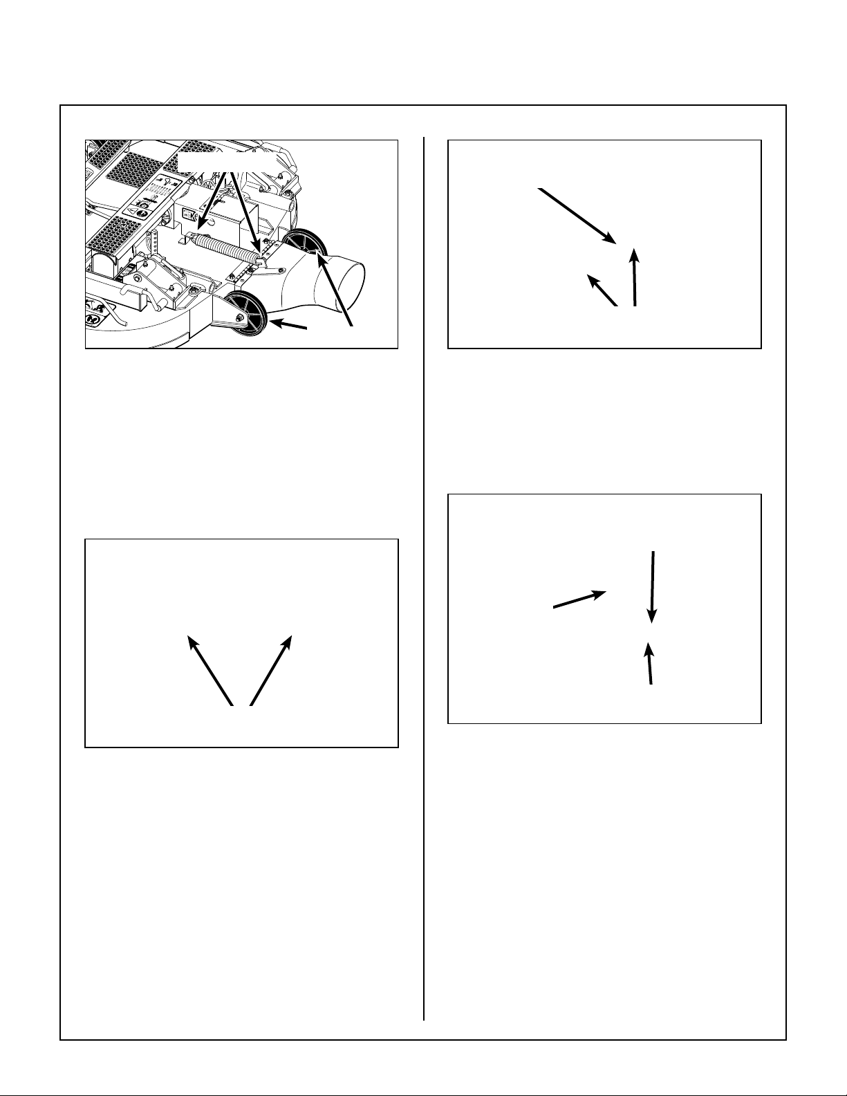
Attach Spring
Roller Wheels
Tilt-Up Spring and Roller Wheel
Installation on Rear Discharge Deck
Mower Deck Installation on Tractor
Deck Installation
1. Lightly grease each deck support arm (2) on the
tractor. Refer to Mower Deck Installation
photo for location of deck support arm.
PTO
Connection
Arrows on Shaft and Tube
(Used to Align When Sliding Together)
PTO Shaft Connection
4. Install the hitch pin through the hole on the end
of each support arm to lock the deck in place
(refer to Deck Counterweight Spring Installa-
tion photo). Two (2) hitch pins are included in
the Owner’s Packet of materials.
Spring T ension Adjustment Nut
Located Under Lower
Spring Hook (Not Visible)
Deck Support
Arms
Mower Deck Installation
2. Engage the deck carrier frame tube sockets on
the tractor support arms (refer to Discharge
Chute and PTO Shaft Guard Installation photo for socket location). Slide the deck onto the
support arms approximately 3 in. (76 mm).
3. Align and connect the splined PTO shaft and
socket halves, as shown in PTO Shaft Connec-
tion photo. The PTO shaft has a pilot end to
ease alignment of shaft; t shaft end into socket
and rotate shaft until the splines line up as indicated by arrows, then slide together.
Counterweight
Springs Clip
Onto Body
With Forward
Body Tilted Up
Hitch Pins Lock Deck
on Support Arms
Deck Counterweight Spring Installation
5. Raise mower body (instead of lifting the front of
deck) and clip the counterweight springs to the
receptacle on front of body. Lower the body to
tension the springs. (Refer to Deck Counter-
weight Spring Installation photo.)
6. With the counterweight springs connected, the
weight on the deck caster wheels should be
15 to 25 Ib (6.8 to 11.3 kg); this adjustment is
preset at the factory . If required, the spring tension can be adjusted by tightening or loosening
the elastic stop nuts located underneath the
lower spring hook, or contact your local dealer
if additional help is required. Refer to Deck
Counterweight Spring Installation photo.
21

Assembly Instructions
Deck Leveling
1. Position mower on a smooth, level surface. Set
the cutting height to the highest position - 4 in.
(102 mm) - for easy access under the deck to
measure blade height. Refer to ADJUSTING
CUTTING HEIGHT in Operating Instructions.
NOTE: A block of wood cut 4 in. (102 mm) high
is a convenient gauge to measure blade height
above ground during the leveling process.
WARNING
The machine must be shut off during this
procedure.
2. Check the side-to-side level. Rotate each
blade sideways and measure the distance
from blade tip to ground on each side. If measurements vary more than 1/8 in. (3 mm), add a
washer shim under the deck support pins on the
low side to level the deck.
3. Check the front-to-rear level. Rotate the blades
to point forward. Measure the distance from
blade tip to ground on the front and rear. The rear
of the blade should be 1/8 to 1/4 in. (3 to 6 mm)
higher than the front of the blade; shim the rear
(or front) deck support pins equally to achieve at
least 1/16 in. (2 mm) difference.
NOTE: The mower deck and support frame are
jig welded; within normal tolerances, very little, if
any, shimming should be required to level the
deck. Tire pressure will inuence the levelness
of the deck. Check the tire pressure as a possible cause of the deck not being level.
4 in. (102 mm)
Wood Block
Should not vary more
than 1/8 in. (3 mm)
side-to-side
Should be 1/8 in. (3 mm)
to 1/4 in. (6 mm) higher
at the rear of the blade
4 in. (102 mm)
Wood Block
22
Deck Leveling
Loading...