

Page 1

OWNER’S MANUAL
Safety, Assembly, Operating, and Maintenance Instructions
Model MT (20.0 / 25.0 HP)
(Covers Serial Numbers 95-21329 and on)
™
Please Read and Save These Instructions Effective Date: 08-14-98
For Safety, Read All Safety and Operation P/N 8000-1
Instructions Prior to Operating Machine Price $5.00
Page 2

Foreword
Thank you. . .for purchasing a Walker mower. Every effort has been made to provide you with the
most reliable mower on the market, and we are sure you will be among our many satisfied customers. If for any reason this product does not perform to your expectations, please contact us at (970)
221-5614. Every customer is important to us. Your satisfaction is our goal.
Please. . .read this manual thoroughly! T his manua l is to b e used in conj unction with the engine
manufacturer’s manual for the specific engine on the mower model you have purchased. Before you
operate your new mower, please read this entire manual. Some of the information is crucial for proper operation and maintenance of this mower - it will help protect your investment and ensure that the
mower performs to your satisfaction. Some of the information is important to your safety and must
be read and understood to help prevent possible injury to the operator or others. If anything in this
manual is confusing or hard to understand, please call our service department, at (970) 221-5614,
for clarification before operating or servicing this mower .
This manual covers Model MT with the K ohl er Com man d CH20 (20.0 HP) gasoline engine, or optional Kohler Command CH25 (25.0 HP) gasoline engine.
All shields and guards mu st be in place for th e proper and safe operatio n of this machine.
Where they are shown removed in this manual, it is for illustration purposes only. Do not operate
this machine unless all shields and guards are in place.
Specifications given are based on the latest information available at the time this manual was produced.
Walker Mfg. Co. is continually striving to improve the design and perfo rmance o f its products. We
reserve the right to make changes in specifications and design without thereby incurring any obligation relative to previously manufactured products.
Sincerely,
WALKER MANUFACTURING COMPANY
Bob Walker, President
Page 3

Table of Contents
General Information ________________ 1
HIGHLIGHTED INFORMATION _____________ 1
GLOSSARY ____________________________ 1
IDENTI FY ING NUMBER LOCATIONS________ 1
ENGINE SERIAL NUMBER LOCATION ______ 2
SERVICING OF ENGINE
AND DRIVETRAIN COMPONENTS __________ 2
Specifications _______________________ 3
ENGINE____________________ ____________ 3
ELECTRICAL SYST EM ___________________ 3
TRANSMISSION_________________________ 3
BLADE DRIVE ______________ ____________ 4
TIRE SIZE ______________________________ 4
TIRE PRESSURE ________________________ 5
DIMENSIONS (Tractor and Mower) ___ ______ 5
MOWER DECK__________________________ 5
CURB WEIGHT__________________________ 5
DRIVE BELTS________ ___________________ 6
GHS SYSTEM (Optional)__________________ 6
SEAT__________________________________ 6
FRAME/BODY CONSTRUCTION ___________ 6
Compo ne n t Identific a tion___________ 7
Safety Ins tructions _________________ 10
BEFORE OPERATING___________________ 10
OPERATING___________________________ 11
MAINTENANCE ________________________ 12
SAFETY, CONTROL,
AND INSTRUCTION DECALS________ _____ 14
Assembly In structions _____________ 16
SETUP INSTRUCTIO N S _________________ 16
Tire Installation (Tractor)__________ _____ 16
Battery Service_______________________ 1 6
Wet Battery Service
Dry Battery Service
Battery Charging
Battery Installation
Mower Deck Assembly ___________ _____ 17
Deck Caster Wheels Installation
Deck Discharge Chute Installation
Deck Discharge Shield Installation
PTO Shaft Guard Installation
Mower Deck Installation on Tractor ______ 18
Deck Installat ion
Deck Leveling
PREOPERATING CHECKLIST ____________ 21
__________________ 16
______________ _____ 16
________________ _____ 17
______________ _____ 17
_________ 17
_______ 18
_______ 18
___________ 1 8
_____________________ 18
_______________________ 20
Operating Instructions_____________ 24
CONTROL IDENTIFICATION,
LOCA T IO N, AND FUNCTION _____________ 24
Operating Controls ___________________ 24
Engine Choke
Engine Throttle
Forward Speed Control (FSC)
Steering Levers
Blade Clutch (PTO)
Parking Brake
Front Body Latch Release
Transmission Lockout Levers
Cold Start Lever (J ackshaft Drive B elt Release)
Instrument Panel _____________________ 28
Hourmeter
Voltmeter
Oil Pressure Warning Light
Over Temperature Warning Light
Ignition Switch
Light Switch (For Optional Lights)
Warning Horn
STARTING THE ENGINE_________________ 30
ADJUSTING GROUND
SPEED AND STEERING _________________ 31
ENGAGING THE MOWER________________ 32
STOPPING THE MACHINE_______________ 33
ADJUSTING CUTTING HEIGHT ___________ 34
TRANSMISSION LOCKOUT _______ _______ 34
RECOMMENDA TI ONS FOR MOWING ______ 35
RECOMMENDATIONS FOR TILT-UP DECK
OPERATION/TRANSPORT _______________ 36
GRASS HANDLING SYSTEM (GHS) _______ 37
General Information __________________ 38
Clogging Checklist ___________________ 39
Using the Tilt-Up Deck ________________ 40
Using the GHS Catcher________________ 40
Powerfil
“Full” Signal Horn
Cleaning the GHS Exhaust Screen ______ 40
Dumping the Catcher _________________ 41
Tailgate Dumping
Using the Dump Bag
Power Dump Option
________________ _______ 24
_______________ _______ 25
__________ 25
_____________________ 25
__________________ 25
________________ _______ 25
_____________ 26
___________ 26
__________________ _______ 29
___________________ _______ 29
____________ 29
________ 29
_______________ _______ 29
_______ 29
________________ _______ 29
®
___________________ _______ 40
____________________ 40
____________________ 41
_________________ 41
__________________ 42
_26
Page 4

Table of Contents
Maintenance Instructions__________ 44
MAINTENANCE SCHEDULE CHART _______ 44
IMPORTANT TIPS
FOR CARE OF THE KOHLER ENGINE _____ 45
Fuel System _______ _______ ___________ 45
Starting/Stopping _____________________ 45
Cooling System ______________________ 45
Air Cleaner System ___________________ 45
Oil _________________________________ 45
LUBRICATION _________________________ 46
Engine Oil _________ _______ ___________ 46
Engine Break-In Oil
Checking Engine Crankcase Oil Level
Changing Engine Crankcase Oil/Oil Filter
Grease Fitting and Oil Point Lubrication__ 47
Mower Deck Gearbox Lubrication _______ 50
DSD52 or DSD62 Mower Deck Lubrication 50
Tractor PTO Gearbox Lubrication _______ 51
Checking Gearbox Oil Level
Changing Gearbox Oil
Gear Axle Lubrication _________________ 51
Hydrostatic Transmission Fluid _________ 52
Checking Hydrostatic
Transmission Fluid Level
Changing Hydrostatic Transmission Fluid
CLEANING ____________________________ 53
Engine Air Cleaner System _____________ 53
Turbine Precleaner
Donaldson Radialseal™
Air Cleaner (Primary)
Kohler Air Cleaner (Secondary)
Foam Precleaner
Paper Element
Engine Coo ling System___________ _____ 57
Air Intake System
Cylinder Head Cooling Fins
Grass Buildup in Mower Housing________ 58
Non-Tilting Decks
Tilt-Up Decks
GHS Blower _________________________ 59
GHS Exhaust Scre e n__________________ 59
Hydrostatic Transmission Cooling Fins __ 60
CHECKING/SERVICING _________________ 60
Security of Air Filtration Components ____ 60
Battery______________________________ 60
Electrolyte Level
Cleaning the Terminals
Charging the Battery
Tire Pressure ___________________ _____ 61
Sharpen Mower Blades ________________ 61
Drive Belts __________________________ 62
Mower Deck Gearbox Oil Seals _________ 63
Spark Plugs ____________________ _____ 63
___________________ 46
____ 46
_46
____________ 51
________________ 51
______________ 52
__ 52
______________ _____ 54
_________________ 54
_________ 5 6
__________________ 56
____________________ 56
_______________ _____ 57
____________ 57
_______________ _____ 58
__________________ _____ 58
________________ _____ 60
________________ 61
__________________ 61
Fuel Lines and Clamps ________________ 63
Engine Starter _______________________ 63
Blade Brake Action ___________________ 63
REPLACING/REPAIRING ________________ 63
Drive Belts __________________________ 63
Engine PTO Drive Belt
Jackshaft Drive Belt
GHS Blower Drive Belt
Hydrostatic Ground Drive Belt
Fuel Filter _______ ____________________ 69
Blade Overload Shear Bolts ____________ 69
Mower Blades _______________________ 70
Mower Deck Gearbox Replacem en t______ 70
GHS Blower Assembly ________________ 71
GHS Blower Assembly Removal
Blower Wheel Removal
Blower Wheel Installation
GHS Blower Assembly Installation
ADJUSTMENTS________________________ 73
Safety Switches ______________________ 73
Seat Switch
_________________ _______ 73
FSC Neutral-Park Switch
PTO Switch
Tail Wheel Bearing Preload ______ _______ 73
Blade Clutch (PTO) ___________________ 74
__________________ _______ 73
Clutch Engagement/Belt Tension
Clutch Disengagement/Brake Action
Stop Block Eccentric Adjustment
Clutch Idler Pulley Travel Adjustment
Blade Brake Band Adjustment
Transmission Control _________________ 77
Set F orwar d Travel Limit (Stop)
Steering Lever End Play Adjustment
Neutral Function Adjustment
Straight Ground Travel Adjustment
Forward Speed Control Friction Lock____ 79
Tilt-Up Deck Adjustable Stop ___________ 80
Carburetor __________________________ 80
Engine Idle Adjustment
GHS “Full” Signal Horn
with Grass-Pak
®
Switch _______________ 81
________________ 65
__________________ 66
________________ 67
__________ 68
________ 71
_______________ 72
______________ 72
_______ 72
______________ 73
________ 74
_____ 75
________ 76
_____ 76
__________ 76
_________ 77
_____ 78
___________ 78
______ 79
_______________ 80
Troubleshooting
(When Horn Fails to Operate)
__________ 81
Adjustment
(When Horn Sounds at the Wrong Time)
ELECTRICAL SYS TEM__________________ 82
Circuit Breakers_________ _____________ 82
Wiring Diagram _________ ______ _______ 83
__ 82
Operator’s Notes______ _____________ 84
Warranty____________________ _______ 87
Page 5

General Information
HIGHLIGHTED INFORMATION
Walker Manufacturing recommends that any service requiring special training or tools be performed
by an authorized Walker Mower Dealer. There are
several general practices to be aware of in the area
of safety. Most accidents associated with the operation or maintenance of a Walker Mower are
caused by disregarding basic safety precautions or
specific warnings. Such accidents, in most cases,
can be prevented by being aware of the dangers
present.
Information of special importance has been highlighted in bold type in this manual. Refer to Safety
Instructions for the meanings of DANGER, WARN-
ING, CAUTION, IMPORTANT, and NOTE.
GLOSSARY
There are many terms t hat are ei the r uniqu e to t his
equipment or that are use d as acronyms. The following terms and their definitions will help while
using this manual:
• DECK is the mowing attachment mounted on
the front of the tractor which includes the carrier
frame, deck housing, blade drive gearboxes,
and cutter blades.
• FORWARD SPEED CONTROL (FSC) con-
trols the maximum forward speed of the tractor; functioning as a cruise control.
• GRASS HANDLING SYST EM (G HS
mowed materia l and deposits it in the catcher.
) collects
• POWER TAKE-OFF (PTO) transmits engine
power to run the cutter blades and GHS blower.
• POWERFIL
throughout the interior of the grass catcher by
an oscillating delivery spout.
spreads the mowed material
• RIGHT HAND (RH) refers to the right-hand side
of the tractor when the operator is seated facing
forward in the tractor seat.
• SIDE DISCHARGE (SD) mows but does not
collect the mowed material.
• STEERING LEVERS steer the tractor by con-
trolling the dual hydrostatic transmissions.
• TRACTOR is the prime mover, including the en-
gine, drive train, operator seat, and controls to
operate the mower.
• TRANSMISSION LOCKOUT releases the hy-
drostatic transmissions to permit freewheeling
the tractor.
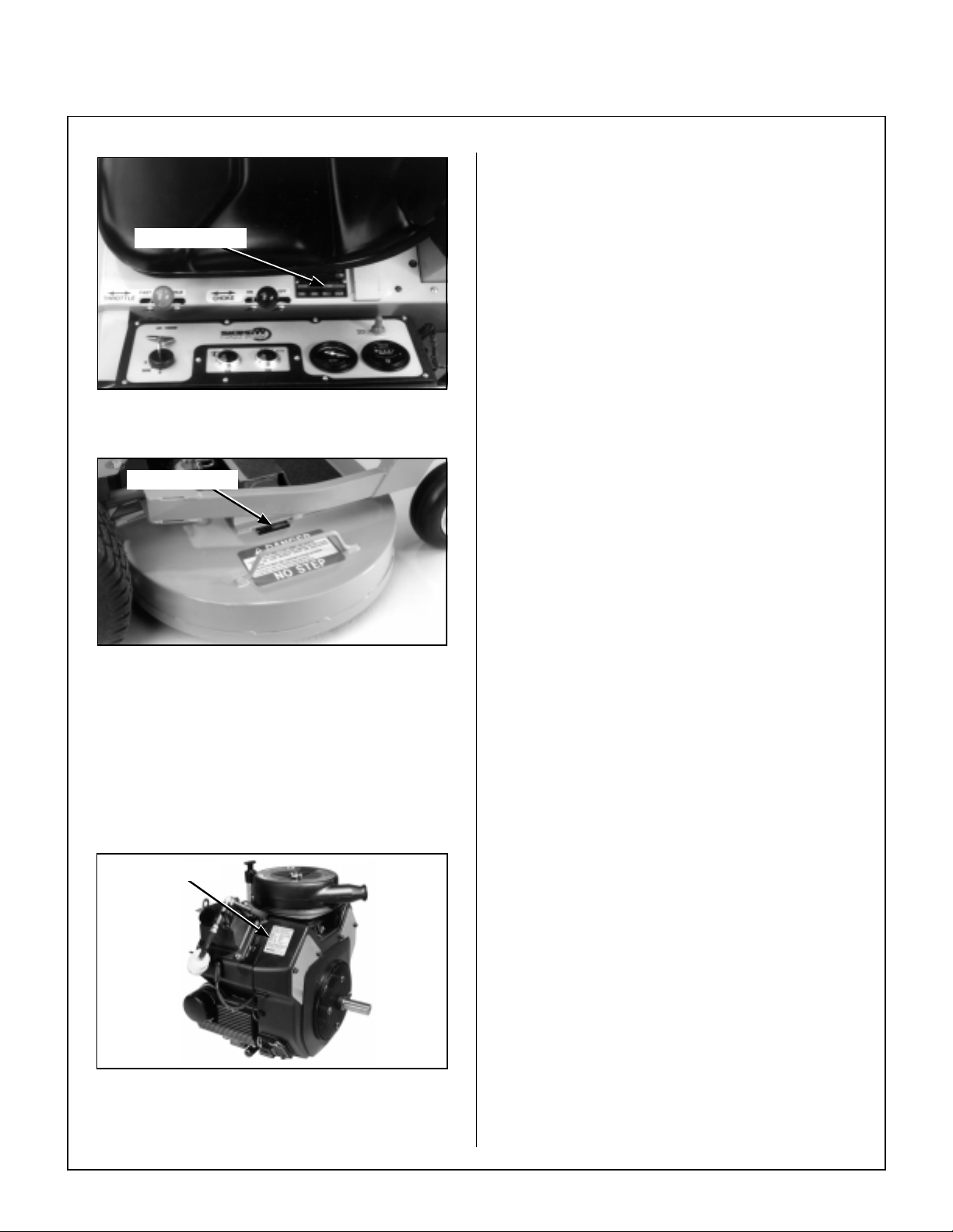
IDENTIFYING NUMBER LOCATIONS
The tractor serial number plate is affixed to t he tractor body just below the left rear corner of the seat.
The mower deck serial number plate is affixed
alongside the angle iron framing on the RH side of
the RH mower blade drive. Model and serial num bers are helpful when obtaining replacem ent parts
and maintenance assistance. For ready reference,
please record these numbers in the space provided.
• GRASS-PAK
grass delivery spout (in the catch er) and acti-
vates the “full” signal horn when the grass
catcher is fu ll.
SWITCH is mounted on the
• GROUND DRIVE refers to the dual hydrostatic
transmissions which drive the main wheels.
• HYDROSTATIC TRANSMISSION transmits
and controls power from the ground drive belt to
the main drive wheel.
• LEFT HAND (LH) refers to the left-hand side of
the tractor when the operator is seated facing
forward in the tractor seat.
Tractor Model No. _______________________
Tractor Serial No. ______________ _______ __
Deck Serial No. _______________________
Engine Model No. _______________________
Engine Serial No. _______________________
Date of Purchase _______________________
Fill In By Purchaser
1
Page 6
General Information
Serial Number
Tractor Serial Number Location
Serial Number
SERVICING OF ENGINE AND DRIVETRAIN
COMPONENTS
The detailed servicing and repair of the engine,
hydrostatic transmission, and gearboxes are not covered in this manual. Only routine maintenance and
general service instructions are provided. For the
service of these components during the limited warranty period, it is important to find a local, authori zed
servicing agent of the component manufacturer.
Any unauthorized work done on these components during t he warranty period may void the war-
ranty. If you have any dif ficulty finding an authorized
outlet or obtaining warranty service, please contact
our Service Department for assistance:
Walker Manufacturing Company
5925 E. Harmony Road
Fort Collins, CO 80528
1-970-221-5614
Service manuals are available for each of these
components from their respective manufacturers as
follows:
Mower Deck Serial Number Location
ENGINE SERIAL NUMBER LOCATION
Refer to the engine manual that accompanies this
manual for the location of the engine serial number .
For the mower model covered by this manual, an engine manual is available coverin g the Kohler CH20
and CH25 gasoline engines.
Serial Number
Kohler Engines Kohler Company
Kohler, WI 53044
Hydrostatic Eaton Cor por a tio n
Transmissions 15151 Highway 5
Eden Prairie, MN 55344
Gearboxes (Deck) Tecumseh Products Co.
900 North Street
Grafton, Wl 53024
Engine Seria l N um ber Location
Page 7

Specifications
3
MODEL
ENGINE
Manufacturer/Model Kohler CH20, 2 Cyl.,
Displacement 38.1 cu. in. (624 cc) 44.0 cu. in. (725 cc)
HP (@ 3600 RPM) 20.0 25.0
Max. RPM (No Load) 3750 3750
Governed RPM 3600 3600
Max. Torque [ft-lb (N
Idle RPM 1200 ± 75 1200 ± 75
Spark Plug Type Champion
Spark Plug Gap .030 in. (.76 mm) .030 in. (.76 mm)
Crankcase Capacity 2.1 qts (2.0 liters) 2.1 qts (2.0 liters)
Crankcase Lubricant API SF, SG, or SH Grade Oil
Fuel Tank Capacity 4.3 Gallons (16.3 liters) 4.3 Gallons (16.3 liters)
Fuel Regular Grade Unleaded
Cooling System Capacity Air Cooled Air Cooled
⋅m) @ RPM] 32 (43.4) @ 2500 39.5 (53.6) @ 2400
MT 20.0 HP MT 25.0 HP
Kohler CH25, 2 Cyl.,
Gasoline (Air Cooled)
RC12YC Champion RC12YC
Only with 10W-30 Viscosity
above 0° F (-18° C), or 5W-20
or 5W-30 Viscosity below 32° F
(0° C)
Gasoline (87 Oct ane)
Gasoline (Air Cooled)
API SF, SG, or SH Grade Oil
Only with 10W-30 Viscosity
above 0° F (-18° C), or 5W-20
or 5W-30 Viscosity below 32° F
(0° C)
Regular Grade Unleaded
Gasoline (87 Octane)
ELECTRICAL SYST EM
Battery 12 Volt, 35AH, 295 CCA 12 Volt, 35AH, 295 CCA
Charging System Flywheel Alternator Flywheel Alternator
Charging Output 1 5 Amp DC (Regulated) 15 Amp DC (Regulated)
System Polarity Negative Ground Negative Ground
Ignition Electronic Capacitive
Discharge
Start er 12 Volt Electric Ring-Gear
Type, Solenoid Shift
Interlock Switch Ignition Lockout by Seat
Switch, Transmission Neutral
and Blade Clutch
Circuit Breaker Manual Reset (30A) Manual Reset (30A)
TRANSMI SS I ON
Manufacturer/Model Dual Hydrostatic, Eaton
Model 7, Each Wheel
Independently Driven
Steering Hand Lever Control /
Individual Wheel
Forward Speed Control Precision Friction Lock Lever,
Cruise Control, with
Neutral-Park Position
Electronic Capacitive
Discharge
12 Volt Electric Ring-Gear
Type, Solenoid Shift
Ignition Lockout by Seat
Switch, Transmission Neutral
and Blade Clutch
Dual Hydrostatic, Eaton
Model 7, Each Wheel
Independently Driven
Hand Lever Control /
Individual Wheel
Precision Friction Lock Lever,
Cruise Control, with
Neutral-Park Position
Page 8

Specifications
MODEL
TRANSMI SS I ON (c on t inue d )
Service Brake Dynamic Braking through
Parking Brake Mechanical Pin Lock in
Neutral Transmission Release by
Final Drive Gear Drive Axle Gear Drive Axle
Transmission Fluid
Factory Servi ce SAE 30W Straight Vi sco sity
Alternate Transmission Fluid Mobil 1 Synthetic Motor Oil
Transmission Fluid Capacity 1 qt (1 liter) 1 qt (1 liter)
Transmission Cooling Cooling Fan Mounted on
Ground Travel Speed
Forward m.p.h. (km/h)
Reverse m.p.h. (km/h)
MT 20.0 HP MT 25.0 HP
Dynamic Braking through
Hydrostatic Transmission
Transmission Gear
Manual Dump Valve
Motor O il (Mobil DTE 18M
Hydraulic Oil Inst all ed at
Factory)
(5W30)
Drive Pulley
0-5 (0-8) Infinitely Variable
0-5 (0-8) Infinitely Variable
Hydrostatic Transmission
Mechanical Pin Lock in
Transmission Gear
Transmission Release by
Manual Dump Valve
SAE 30W Straight Viscosity
Motor Oil (Mobil DTE 18M
Hydraulic Oil Installed at
Factory)
Mobil 1 Synthetic Motor Oil
(5W30)
Cooling Fan Mounted on
Drive Pu lley
0-5 (0-8) Infinitely Variable
0-5 (0-8) Infinitely Variable
BLADE DRIVE
PTO Shaft Quick Disconnect Rectangular
Shaft with Two High-Speed
U-Joints
Blade Spindle Each Blade (2) Moun ts Direct
on Peerless Right Angle
Gearbox with Tee Gearbox
in Center Connected to PTO
Shaft (Complete Geared
Drive, Peerless Model 1000
Gearboxes)
Blade Drive Clutch and Brake Manual Belt Tightener Clutch
and Band Brake (Stops
Blades within Five (5)
Seconds of Disengagement)
Max. Blade Speed
[25 in. (64 cm) Blade]
@ 3600 RPM Engine
TIRE SIZE
Deck Caster Wheel 2.80/2.50-4 Pneumatic (4-Ply) 2.80/2.50-4 Pneumat ic (4-Ply)
Deck Caster Wheel (Optional) 8.25 x 2.75 Semi-Pneumatic 8.25 x 2.75 Semi-Pneumatic
Drive 18 x 9.50-8 (4-Ply) 18 x 9.50-8 (4-Ply)
Rear (Dual) 13 x 5.00-6 (4-Ply) 13 x 5.00-6 (4-Ply)
2400 RPM
[15700 FPM (4785 m/min)]
Quick Disconnect Rectangular
Shaft with Two High-Speed
U-Joints
Each Blade (2) Mounts Direct
on Peerless Right Angle
Gearbox with Tee Gearbox
in Center Connected to PTO
Shaft (Complete Geared
Drive, Peerless Model 1000
Gearboxes)
Manual Belt Tightener Clutch
and Band Brake (Stops
Blades within Five (5)
Seconds of Disengagement)
2400 RPM
[15700 FPM (4785 m/min)]
Page 9

Specifications
5
MODEL
TIRE PRESSURE
Deck Caster Wheel 20 PSI (137 kPa) 20 PSI (137 kPa)
Drive 15 PSI (103 kPa) 15 PSI (103 kPa)
Rear 20 PSI (137 kPa) 20 PSI (137 kPa)
DIMENSIONS (Tractor and Mower)*
Length 91 in. (231 cm) 91 in. (231 cm)
Width 49 in. (124 cm) 49 in. (124 cm)
Height 44 in. (1 12 cm) 44 in. (112 cm)
Wheel Base (Tractor) 4 2-1/4 in. (107 cm) 42-1/4 in. (107 cm)
Tread Width (Tractor) 29-3/4 in. (76 cm) 29-3/4 in. (76 cm)
MOWER DECK
Width of Cut SD/GHS 42 or 48 in. (107 or 122 cm) 42 or 48 in. (107 or 122 cm)
Cutting Height 1 to 4 in. (3 to 10 cm) 1 to 4 in. (3 to 10 cm)
Height Adjustment 7 Positions - 1/2 in. (1 cm)
Blade Size (Typical)
42 in. (107 cm) SD 22 in. (56 cm)
48 in. (122 cm) GHS 25 in. (64 cm)
Deck Suspension Torsion-Flex Frame with
MT 20.0 HP MT 25.0 HP
7 Positions - 1/2 in. (1 cm)
Increment Hitch Pins Installed
in Multi-Position Deck Support
2 in. (5 cm) Center Overlap
(Two Blades, CW Rotation)
2 in. (5 cm) Center Overlap
(Two Blades, Counter Rotate)
Caster Wheels and
Counterweight Springs
Increment Hitch Pins Installed
in Multi-Position Deck Support
22 in. (56 cm)
2 in. (5 cm) Center Overlap
(Two Blades, CW Rotation)
25 in. (64 cm)
2 in. (5 cm) Center Overlap
(Two Blades, Counter Rotate)
Torsion-Flex Frame with
Caster Wheels and
Counterweight Springs
CURB WEIGHT (Approximate)
SD Tractor Only 660 lb (299 kg) 665 lb (302 kg)
GHS Tractor Only 760 lb (345 kg) 765 lb (347 kg)
Tractor and Mower* 965 lb (438 kg) 970 lb (440 kg)
*Dimensions and weight shown are for 48 in. (122 cm) GHS Model (typi cal).
Dimensions for Tractor and Mower with 42 in. (107 cm) deck are:
Length = 88 in. (224 cm)
Width = 43 in. (110 cm)
For SD Models, subtract 7 in. (18 cm) from the height.
Deck weight for 48 in. (122 cm) Tilt-Up deck = 205 lb (93 kg). Deck sizes range from 42 to 62 in.
(107 to 157 cm), with corresponding deck weights ranging from 170 to 300 lb (77 to 136 kg).
Optional (9. 5 Bushel) Grass Catcher adds approx. 5 lb (2 kg) and 5 in. (13 cm) in Height
Page 10

Specifications
MODEL
DRIVE BELTS
Engine PTO Walker P/N 8230 Walker P/N 8230
Jackshaft Drive Gates 3VX355
Ground Drive, Micro-V Walker P/N 7248 Walker P/N 7248
Blower (GHS Model) Gates 3VX280
GHS SYSTEM (Optional)
Blower 4 x 10 x 1/4 in. (10 x 25 x 1 cm)
Blower Brake Band Brake (Works in Combi-
Max. Blower Speed 3 600 RPM 3600 RPM
Grass Catcher Capacity 65 Gallons (246 liters)/
Optional Grass Catcher
Capacity
Full Signal Oscillat ing Vane Switch
Powerf il
®
MT 20.0 HP MT 25.0 HP
Gates 3VX355
(or Walker P/N 6231)
(or Walker P/N 7234)
Three-Blade Paddle Wheel
(Driven by Mower Engine)
nation with PTO Clutch, Stops
Blower within Five (5) Seconds
of PTO Disengagement)
7.0 Bushels
76 Gallons (335 liters)/
9.5 Bushels
Mounted on Grass Delivery
Spout Triggers Horn Signal
Oscillating Delivery Spout
Driven by 12 Volt Electric
Gearmotor Spreads Material
throughout Interior of Catcher
@ 25 Cycles/Minute
(or Walker P/N 6231)
Gates 3VX280
(or Walker P/N 7234)
4 x 10 x 1/4 in. (10 x 25 x 1 cm)
Three-Blade Paddle Wheel
(Driven by Mower Engine)
Band Brake (Works in Combination with PTO Clutch, Stops
Blower withi n Five (5) Seco nds
of PTO Disengagement)
65 Gallons (246 liters)/
7.0 Bushels
76 Gallons (335 liters)/
9.5 Bushels
Oscillating Vane Switch
Mounted on Grass Delivery
Spout Triggers Horn Signal
Oscillating Delivery Spout
Driven by 12 Volt Electric
Gearmotor Spreads Material
throughout Interior of Catcher
@ 25 Cycles/Minute
SEAT
FRAME/BODY CONSTRUCTION
Frame All Welded Unitized Steel
Body 14 Gauge Steel 14 Gauge Steel
Deck 11 Gauge Steel 11 Gauge Steel
GHS Catcher and Chutes Molded Cross-Linked
NOTE: The manufacturer reserves the right to make changes in specifications shown herein at any time
without notice or obligation.
Contour-Molded, with Nylon
Backed Vinyl Cover and
Integral Foam Cushion
Chassis
Polyethylene (UV Stabi l ized)
Contour-Molded, with Nylon
Backed Vinyl Cover and
Integral Foam Cushion
All Welded Unitized Steel
Chassis
Molded Cross-Linked
Polyethylene (UV Stabilized)
Page 11
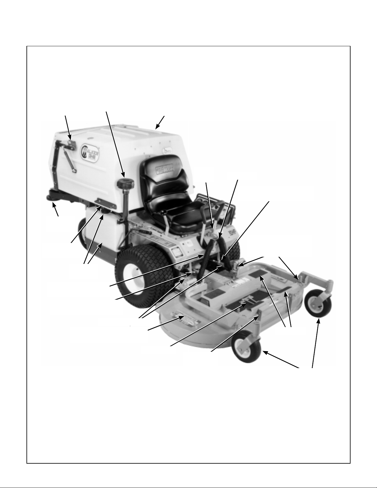
Component Identification
7
NOTE: Control Identification
shown in Operating
Instructions section.
Catcher Door
Safety Latch
Anti-Scuff
Roller
Catcher Lift /
Dump Handle
Fuel Tank
and Cap
Tu rbine
Precleaner
Grass Handling System
7.0 Bushel Catcher
Tilt-Up
Latch
Spring Clip
Transmission Control Rod
Adjustment Nut (LH)
Deck Support Pins
and Height Adjustment
Hitch Pins
Counterweight Spring
and Protective Cover
Transmission Control Rod
Adjustment Nut (RH)
Deck Support Arms
Deck Lift Handle
(Cutting Height Adjustment)
Footrests
Tilt-Up Hook
Tilt-Up
Deck Handle
Deck
Caster Wheels
Front View an d R ig ht Side View
Page 12
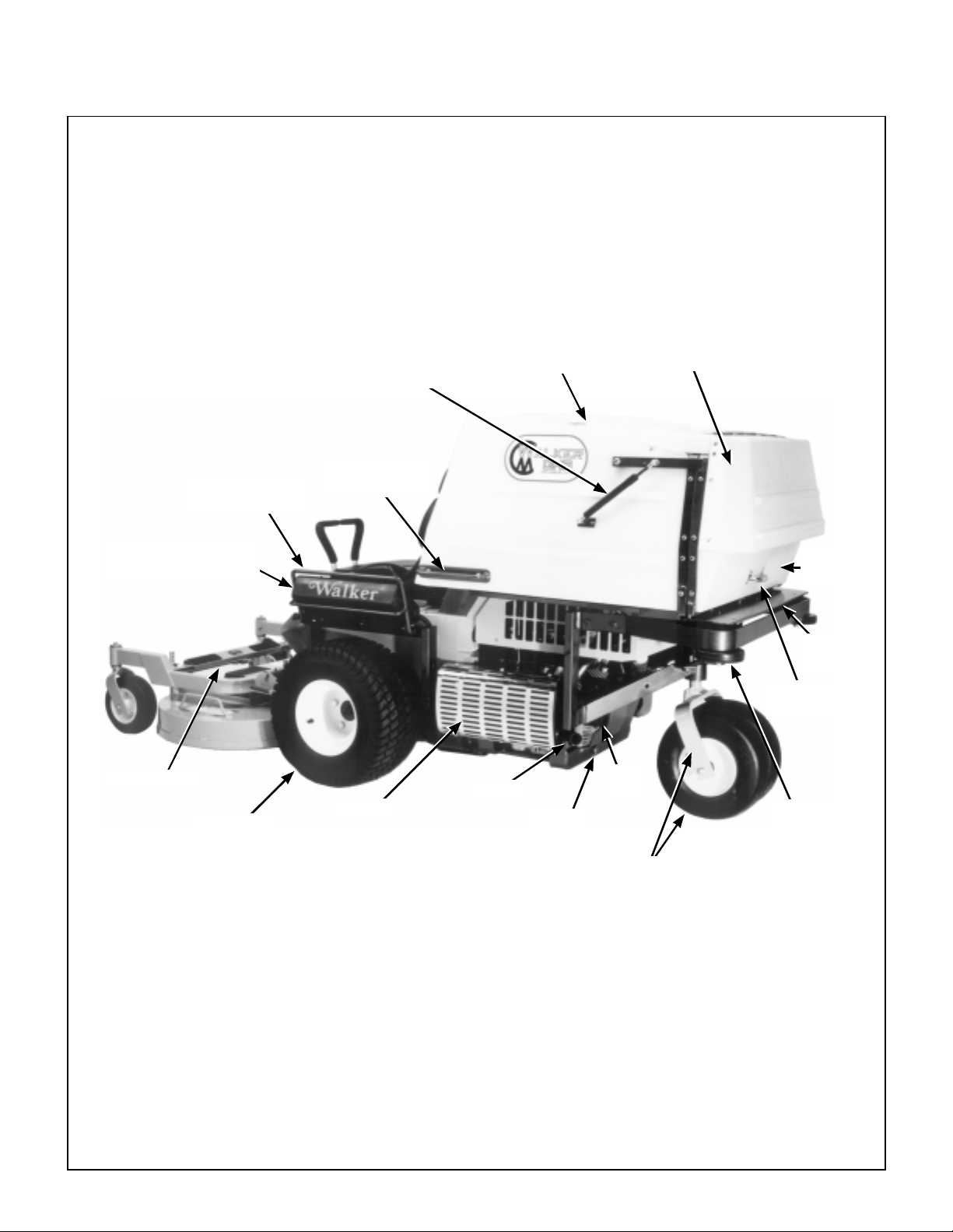
Component Identification
Instrument Panel
Guard
Instrument Panel Box
(Shock Mounted)
Deck Lift Rod
Left Hand
Drive Wheel
Catcher Door
Gas Spring
Catcher Lift /
Dump Handle
Muffler
Removable Grass
Catcher Screen
(Not Visible)
Tailpipe
Oil Drain
Plug
Catcher Exhaust
Deflector
Catcher
Door
Dump
Plate
Catcher
Door Handle
Oil
Filter
Anti-Scuff
Roller
Tailwheel Fork
and Wheels
Rear View and Left Side View
Page 13
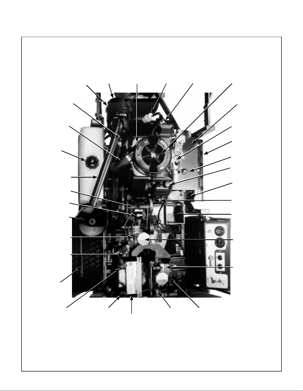
Component Identification
9
Donaldson Air Cleaner
(Primary Air Cleaner)
Air Restriction Indicator
(Not Visible)
Air In take Ho s e
(Primary to Secondary)
Fuel Tank
Precleaner
Tube
Jackshaft
PTO Gearbox
Dipstick
Turbine
Precleaner
Air Cleaner
Cover
Air Cleaner
Base P la t e
Fuel Filter
Fuel Pump
Engine Air Cleaner
(Secondary)
Muffler Gras s
Shield
Throttle and
Choke Linkage
Muffler Heat
Shield
Oil Dipstick/Oil Fill
Rubber Bumper
(Catcher Support)
Muffler
20 Amp Fuse
(Starter Solenoid)
GHS Blower
RH Transmission
Lockout Lever
30 Amp
Circuit Breaker
PTO
Clutch Lever
Positive (+)
Battery Cable
Negative (-)
Battery Cable
Neutral Safety
Battery
Top View (Engine Compartment)
Switch
RH Hydrostatic
Transmission
LH Hydrostatic
Transmission
LH Transmission
Lockout Lever
Page 14
Safety Instructions
Pay particular attention to any information labeled
DANGER, WARNING, CAUTION, IMPORTANT,
and NOTE in this manual.
When you see the Safety Alert Symbol ( ),
read, understand, and follow the in structions. Failure to comply with safety instructions may result in
personal injury.
The seriousness or degree of importance of each
type of information is defined as follows:
DANGER
An IMMEDIATE hazard that WILL result in
severe personal i njury or DEATH, if warning is ignored and proper safety precautions are not taken.
WARNING
A POTENTIAL hazard that COULD result in
sev ere pers onal inju ry or DEATH, if w arning is ignored and proper safety precautions are not taken.
Walker Manufacturing cannot predict every potentially dangerous situation. Therefore, items labeled
as such in this manual do not cover all conceivable
situations. Any person using procedures, tools, or
control techniques not recommended by Walker
Manufacturing must take full responsibility for safety.
The Walker Rider Lawnmower has been designed
with many safety features to protect the operator from
personal harm or injury. However , it is necessary for
the operator to use safe operating procedures at all
times . Failure to follow safety instructions con-
tained in this manual may result in personal injury or dama ge t o equipment or property.
If you have any questions concerning setup, operation, maintenance, or safety, please contact your
authorized Walker Mower Dealer or call Walker
Manufacturing Company at (970) 221-5614.
BEFORE OPERATING
1. Read and understand the contents of this
Owner’s Manual before starting and operating the machine. Become thoroughly f am iliar
with all ma chine controls and how to stop the
machine and disengage the controls quickly.
Replacement Owner’s Manuals are available
by sending the Model and Serial Number to:
CAUTION
Possible hazards or unsafe practices that
MAY result in MOD ERATE per sonal injury
or property damage, or machine damage, if
warning is ignored and proper safet y precautions are not taken.
IMPORTANT: Identifies mechanical information de-
manding spec ial at tention, s ince it de als wit h the pos sibili ty of damaging a par t or parts of th e m ach i ne.
NOTE: Identifies information worthy of special
attention.
Walker Manufacturing Company
5925 East Harmony Road
Fort Collins, CO 80528
2. Never allow children to operate rider mower.
Do not allow adults to operate without prope r
instructio n.
3. Clear the area to be mowed of any foreign
objects which may be picked up and thrown by
cutter blades. Pick up all sticks, stones, wire,
and any other debris.
4. Keep every one, espec ially ch ildren and pets, a
safe distance away from the area being mowed.
Do not mow with bystanders in the area.
5. Do not operate the machine barefoot or wearing
sandals, sneakers, tennis shoes, or similar lightweight footwear. Wear substantial protective
footwear.
10
Page 15

Safety Instructions
6. Do not wear loose fitting clothing that could get
caught in moving parts. Do not operate this
machine while wearing shorts; always wear
adequate protective cloth ing, including long
pants. Wearing safety glasses, safety shoes,
and a helmet is advisable and required by some
local ordinances and insurance regulations.
7. Prolonged exposure to loud noise can cause impairment or loss of hearing. Operator hearing
protection is recommended; particularly for
continuous operation of t he GHS M odel due to
blower noise level. Wear a suitable hearing protective device, such as earmuffs or earplugs.
8. Keep all protective shields and safety de-
vices in place. If a protective shield, safety
device, or decal is damaged, unusable, or missing, repair or replace it before operating the
machine.
9. Be sure interlock switches are functioning
correctly, so the en gine ca nnot be started unless the Forward Speed Control lever is i n the
NEUTRAL-PARK position, and the PTO clutch
is in the DISE NGAGED position. Also, the engine should stop if the operator lifts off the seat
with the PTO clutch in the ENGAGED position.
10. Handle gasoline with care. Gasoline is highly
flammable and its vapors are explosive:
a. Use an approved fuel container.
12. The electrical system battery contains sulfuric
acid. Avoid any c ontact with skin , eyes, and
clothing. Keep the battery and acid out of reach
of children.
OPERATING
1. Operate the mower only in daylight or in
good artificial light with good visibility of the area
being mowed.
2. Sit on the seat when starting the engine and
operating the machine. Keep feet on the deck
footrests at all times when the tractor is moving
and/or mower blades are operating.
3. For a beginning operator, learn to steer (ma-
neuver) the tractor with a slow engine speed
before attempting any mowing operation. Be
aware that, with the front mounted mower configuration, the back of the tractor swings to the
outside during turns.
4. Remember, for an emergency stop, the forward
motion of the tractor can always be stopped by
pulling the Forward Spee d Control (FSC) into
the NEUTRAL-PARK position.
5. Disenga ge the blade clutch and put the FSC in
the NEUTRAL-PARK position before starting
the engine (an ignition interlock switch normally
prevents starting of the machine i f these controls are in the OPERATING position).
b. Never add fuel to a running engine or hot
engine (allow hot engine to cool several
minutes).
c. Keep matches, cigarettes, cigars, pipes,
open flames, or sparks away from the fuel
tank and fuel container.
d. Always fill the fuel tank outdoors using care.
Fill to about one inch from the top of the tank.
Use a funnel or spout to prevent spilling.
e. Replace the machine fuel cap and container
cap securely and clean up any spilled fuel
before starting the engine.
11. Never attempt to make any adjustments
while the engine is running, except where specificall y instructed to do so.
6. Do not run the engine in a confined area with-
out adequate ventilation. Exhaust fumes are
hazardous and can be deadly.
7. Do not carry passengers - maximum seating
capacity is one (1) person.
8. Watch for holes, rocks, and roots in the terrain
and for other hidden hazards. When mowing tall
grass, mow higher than desired to ex pose any
hidden obstacles. Then, clean the area and
mow to the desired height.
9. Avoid sudden starts or stops. Before backing
the machine up, look to the rear to be sure no
one is behind the machine. Watch carefully for
traffic when crossing or working near roadways.
11
Page 16

Safety Instructions
10. Disengage the blade drive when transporting
the machine across drives, sidewalks, etc. Ne-
ver raise the mowe r deck while blades are
rotating.
11 . The maximum recommended side slope op-
erating angle is 20 degrees or 33% grade.
When operating the machine on a slope, reduce
speed and use caution to start, stop, and maneuver. To prevent tipping or loss of control of
the machine, avoid sharp turns or sudden
changes in direction.
12. Never adjust cutting height with the engine
running. Before adjusting cutting height or servicing, disengage the blade clutch (PTO), stop
the engine, and rem ove the ignition key. Wait
for all movement to stop before getting off the
seat.
NOTE: A blade/blower brake should normally
stop drive line rotation within five (5) seconds of
disengaging the PTO clutch.
13. For side discharge mower decks, do not oper-
ate with the grass d eflec tor ch ute rem ov ed.
Keep the deflector in the lowest possible position.
14. For tractors equipped with tilt-up deck, observe
the following recommendations:
17. In case of a clogged or plugged mower deck
or GHS catching system:
a. Disengage the blade clutch (PTO) and turn
the engine off before leaving the seat.
b. LOOK to make s ure blade drive shaft and
blower drive pulley movement has stopped
before trying to unclog the system.
c. Disconnect the spark plug wires.
d. Never place hands under the deck or in the
GHS blower - use a stick or similar tool to
remove clogged material.
18. If the cutting bl ades strike a solid o bject or the
machine begins to vibrate abnormally, immed i-
ately disengage the blade clutch (PTO), stop
the engine, and wait for all moving parts to
stop. To prevent accidental starting, discon-
nect the spark plug wires. Thoroughly inspect
the mower and repair any damage bef ore restarting the engine and operating the mower.
Make sure cutter bl ades are in good condition
and blade nuts are torqued to 60 ft-lb (81.3 N
19. Do not touch the engine or muffler while the
engi ne is ru nning or immediately after stopping
the engine. These areas may be hot enough to
cause serious burns.
⋅m).
a. Do not move tractor with deck in tilt-up po-
sition.
b. Never tilt body forward with deck in tilt-up
position.
15. For GHS equipped models, do not operate the
machine with the grass catcher in the DUMP
position or with the back door OP EN. Dan-
gerous projectiles may be thrown out of the discharge chute or the back of the grass catcher.
16. For GHS equipped models, use care when
closing the grass catcher door . Keep fingers
and hands away from the hinge and pinch
points when the door is being closed. Also,
keep fingers and hands clear of the door frame.
The door is held closed with springs and the
door may slam shut with considerable force.
20. When leaving the machine unattended, dis-
engage the blade clutch (PTO), stop the engine, and remove the key.
MAINTENANCE
1. To prevent accidental starting of the engine
when servicing or adjusting the machine, remove the key from the ign ition switch and disconnect the spark plug wires.
2. To reduce fire hazards, keep the engine free of
grass, leaves, excessive grease, and dirt.
3. Keep all nuts, bolts, and screws tight to en sure
the machine is in a safe, working condition.
Check the blade mounting nuts frequently, making sure they are tight.
12
Page 17

Safety Instructions
3
4. Perform only maintenance instructions de-
scrib ed in th is manua l. Unauthorized maintenance operations or machine modifications
may result in unsafe operating conditions.
5. If the engine must be running to perform a maintenance adjustment, keep hands, feet, and
clothing away from moving parts. Do not wear
jewelry or loose clothing.
6. Al ways u se the proper en gine service manual when working on the engine . Unautho-
rized maintenance operations or mo difications
to the engine may result in unsafe operating
conditions.
7. Altering the equipment or engine in any manner
which adversely affects its operation, performance, durability, or use will VOID the warran-
ty and may cause hazardous conditions.
8. Never attempt to disconnect any safety devices
or defeat the purpose of these safety devices.
9. Do not change the engine governor settings or
overspeed the engine. The governor has been
factory-set for maximum-safe engine ope rating
speed.
d. Disconnect both battery cables before
unplugging any wiring connectors or making repairs on the electrical system.
IMPORT ANT: Keep all applicable manuals
immediately accessible to anyone who may
operate or service this machine.
10. Use genuine factory replacement parts.
Substitute parts may result in product malfunction and possible injury to the operator and/or
others.
11 . Use care w hen charging the battery or per-
forming maintenance on the battery and electrical system:
a. Make sure the battery charger is unplugged
before connecting or disconnecting cables
to the battery.
b. Charge the battery in a well-ventilated
space, so gases produced whil e charging
can dissipate. Make sure the battery vents
in the caps are open.
c. Keep s parks, flames, and smoking materi-
als away from the battery at all times. To
avoid sparks, use care when removing battery cables from posts.
1
Page 18

Safety Instructions
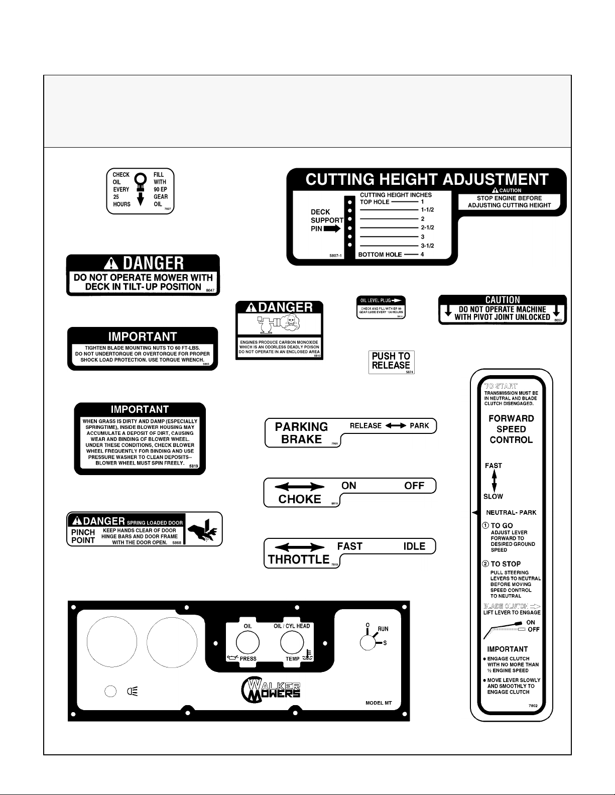
SAFETY, CONTROL, AND INSTRUCTION DECALS
Safety, Control, and Instruction Decals are installed on the machine;
if any are missing, illegible, or damaged, a replacement should be ordered and installed before
putting the machine into operation. The Decal Pa rt Number is l isted below and in the Parts Manual.
Each End of Mower Deck (5808)
Adjacent to Blower Discharge Chute
through Body (5804)
SD Deck Discharge Shield (5848)
On Body Adjacent to Clutch
Control Lever (5806)
Right Si de of Fro nt Body, Below
Front Body Latch Release (7820)
Hydrostat Oil
Front Body Adjacent to
RH Steering Lever (7818)
Engine Shroud (5855)
Rear of Grass Catcher Exhaust Screen (5869)
Rear Cross Member of Front Body (8825)
Reservoir (5810)
14
Page 19
Safety Instructions
5
SAFETY, CONTROL, AND INSTRUCTION DECALS
Safety, Control, and Instruction Decals are installed on the machine;
if any are missing, illegible, or damaged, a replacement should be ordered and i nstalled before
putting the machine into operation. The Decal Pa rt Number is listed below and in the Parts Manual.
Jackshaft Support Adjacent
to Dipstick (7827)
Deck Carrier Frame (8647)
Deck Gearbox Cover (5807-1)
Deck Carrier Frame (5865)
Top of Blower Housing (5819)
Catcher Door Hinge Bar,
LH and RH Sides (5868)
Gear Axle (5810-1)
On Engine (6810)
Catcher Safety Latch,
RH Side (5874)
Right Side, Below Operator Seat (7809)
Left Side of Operator Seat (8819)
Left Side of Operator Seat (7819)
Deck Carrier Frame (8653)
Instrument Panel (8823)
Fender, RH Side (7802)
1
Page 20
Assembly Instructions
SETUP INSTRUCTIO N S
Walker Mowers are shipped partially assembled.
After uncrating the tractor and mower de ck, initial
setup is required.
NOTE: During the proc es s of unp ac ki ng, any d amaged or missing parts should be noted and reported
to the delivering carrier im mediately (put in writing
within 15 days). The carrier will provide directions
for proceeding with a claim to receive compensation
for damage.
Tire Installation (Tractor)
• Install the drive tires using the eight (8) lug bolts
that are supplied with the owner’s packet of materials. Drive tires are 18 x 9.50-8, 4-ply; rear tires are
13 x 5.00-6, 4-ply.
• Check and adjust the inflation of the tires. The
tire inflation recommendations are:
Drive = 15 PSI (103 kPa)
Rear = 20 PSI (137 kPa)
Battery Service
Raise front mower body up for battery access (refer
to
Front Body Latch Release
tions). Check the battery for electrolyte level and
charge. The electrolyte level should be at the bottom of the vent wells [1/4 to 1/2 in. (6 to 13 mm)
above plates]. If the specific gravity is less than
1.225, the battery needs charging. If the battery
has been shipped dry, or is wet but needs service,
refer to the following instructions.
Wet Battery Service
If the battery has been shipped wet, but the electrolyte level is low or the battery needs to be charged
then:
1. Fill each battery cell with dri nking water to the
bottom of the vent wells.
2. Charge battery. Refer to
this section .
in Oper ating I nstruc -
Battery Charging
in
Dry Battery Service
DANGER
Activating a battery can be dangerous.
The battery should be taken to a reliable
service station, battery store, or power
equipment dealer where a tra ined techni cian can activate the battery safely. DO
NOT attempt to activate the battery unless
you are experienced in battery service
work. The following activation and charging instructions are provided for use by a
trained battery technician.
DANGER
Battery electrolyte is a poisonous and corrosive sulfuric acid solution.
• Avoid spillage and contact with skin,
eyes, and clothing - causes severe burns.
• To prevent accidents, wear safety gog-
gles and ru bber gloves when working with
electrolyte.
• Neutralize acid spills with baking soda
and water solution.
T o fill (activate) battery with electrolyte (if battery has
been shipped dry):
1. Remove the batte ry hold do wn bar, disconnect
the battery cables and lift th e batte ry out of the
tray.
IMPORTANT: Battery must be removed from
the mower before filling with electrolyte.
IMPORTANT: Obtain and use only battery
grade sulfuric acid electrolyte with a 1.265 specific gravity to activa te the ba ttery. DO NOT use
water or any other liq ui d duri ng ini t i al act ivation.
16
2. Remove the filler caps and carefully fill each cell
until the electrolyte is just above the plates.
Page 21
Assembly Instructions
7
3. After the battery is filled with electrolyte, replace
the filler caps and charge the battery. Refer to
Battery Charging
Battery Charging
.
DANGER
WARNING
Make sure the battery cap vents are open.
Improper venting of the battery COULD
cause a battery explosion.
BATTERIES PRODUCE EXPLOSIVE GASES
• Charge the battery in a well-ventilated
area, so that gases produced while charging can dis sipat e.
• Keep sparks, flames, and smoking mate-
rials away from the battery at all times.
• Make sure the battery cap vents are
open after the battery is filled with acid
(check manifold vent on each cap).
• Make sure the battery charger is unplug-
ged before connecting or disconnecting
cables to the battery.
1. Charge the battery at 15 a mps for 10 min utes.
DO NOT exceed 20 amps maximum recommended charging rate. Charge until specific
gravity is at least 1.250. Total charging time
should not exceed one (1) hour.
2. After charging the battery , adjust t he el ectrolyte
level to the bottom of the vent wells [1/4 to 1/2 in.
(6 to 13 mm) above the plates].
IMPORTANT: DO NOT overfill the battery.
Electrolyte will overflow through the vented caps
onto parts of the machine and WILL result in
severe corrosion.
Battery Clamp
Secured by
Wing Nut(s)
(+) Battery Cable
Connection
Battery Installation
Mower Deck Assembly
Deck Caster Wheels Installation
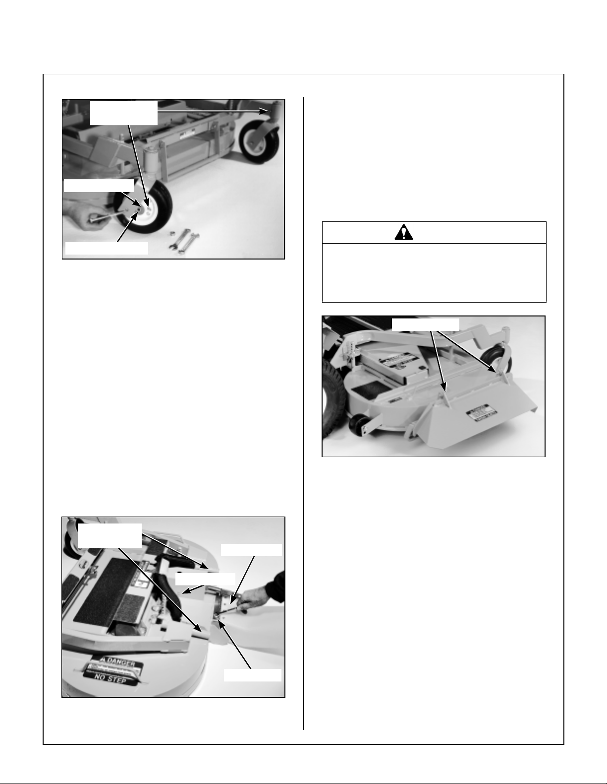
1. Remove the bolt, nut, axle spacer tube, and
spacer washers from e ach deck caster wheel
fork.
NOTE: Spacer washers are used only when
the optional semi-pneumatic deck wheels (8.25
x 2.75) are installed.
2. Fit the axle spacer tube through the wheel hub,
position the spacer washer on each s id e of the
hub (if used), and fit the assembly into the wheel
fork.
3. Install battery.
Battery Installation
Install the battery in the mower as shown in Battery
Installation photo. Connect the positive and negative cables to the proper battery terminal (red cable
and boot connects to the Positive (+) terminal).
Slide the rubber boot up and o ver the batte ry post,
making sure it covers t he post completely to p re-
vent an electrical short.
3. Insert the 3/8-16 x 4-1/2 in. bolt through the
wheel fork with the bolt head to the outside and
install the 3/8-16 in. Keps nut.
4. Tighten the bolt and nut until the axle spacer
tube bottoms against the inside of the wheel
fork (will not tu rn) while the wheel an d spacer
washers (if used) spin freely without binding.
1
Page 22
Assembly Instructions
Grease Fitting
Locations
Spacer Washer
Axle Spacer Tube
Deck Caster Wheel Installation
NOTE: If semi-pneumatic wh eels are i nst alled ,
make sure the spacer washers fit over the spac er
tube and are not caught between the fork and the
end of the tube. The washers shoul d move freely
on the axle spacer tube.
5. Grease the caster wheel bearings and caster
pivot bearings - one grease fitting for each wheel
and each pivot.
Deck Discharge Shield Installation (Side Discharge Models Only)
Attach the deck side discharge shield by posit ioning
the shield hinge lug in front of the deck mount and
fastening with two 3/8-16 x 1-1/4 in. bolts, 3/8-16
ESNA nuts, and 3/8 in. wave spring washers. The
wave washers fit between the two hinging surfaces.
Tighten the nuts until the shield moves freely but is
not loose.
WARNING
DO NOT operate the m achine witho ut th e
grass deflector chute attached and in the
lowest possible position.
Attach Shiel d
Deck Discharge Chute Installation (GHS Rear Discharge Models Only)
Mount the discharge chute hinge on top of the deck
discharge opening using the 1 /4-20 x 1 /2 in. socket
button head bolt and 1/4-20 ESNA nut. Position the
bolt with the head inside of the chute and the nut on
the outside.
Carrier Frame
Tube Sockets
Attach Chute
Attach G u ard
Nut on Top
Discharge Chute and PTO Shaft Guard
Installation on Rear Discharge Deck
Discharge Shield Installation
on Side Discharge Deck
PTO Shaft Guard Installation
Position the shaft guard as shown and mount with
two 1/4-20 x 1/2 in. bolts.
Mower Deck lnstallation on Tractor
Deck Install ation
1. Lightly grease each deck support arm (2) on the
tractor. Refer to Mower Deck Installation pho-
to on next page for location of deck support arm.
2. Engage the deck carrier frame tube sockets on
the tractor support arms (refer to Discharge
Chute and PTO Shaft Guard Installation
photo for socket location). Slide the dec k onto
the support arms: all the way if SD equipped
model, approximately 3 in. (76 mm) if GHS
equipped model.
18
Page 23
Assembly Instructions
9
NOTE: When installing the DSD52 or DSD62
Mower deck, make sure to retract the dolly
wheel after mounting the deck on the tract or.
3. If the deck is rear discharge (GHS equipped
model), the rear discharge chute will need to be
aligned and connected to the blower inlet during the last 2 in. (51 mm) of slid e act ion on th e
support arms.
NOTE: Raising the mower body may be helpful in fitting and guiding the deck chute into the
blower.
4. Install the hitch pin through the hole on the end
of each supp ort arm to lock the deck in place
(refer to Deck Counterweight Spring Installa-
tion photo). Two (2) hitch pins are included in
the owner’s packet of materials.
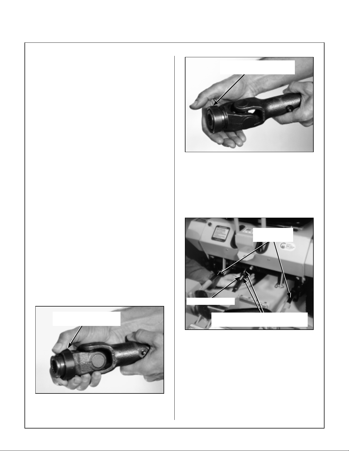
5. Connect the mower deck PTO drive shaft
assembly to the tractor with the splined quick
disconnect coupler. This coupler simplifies
shaft alignment and installation.
a. Use the arrows on the shaft and tube to
align and slide the PTO quick coupler onto
the deck rectangular shaft.
b. Reaching under the tractor, pull the ring
back on the coupler, slide onto the spline
shaft on the tractor, and release the ring.
Spring-Loaded Coupler Ring
In Fully Forward Position
Coupler Rin g “L oc ked” Position
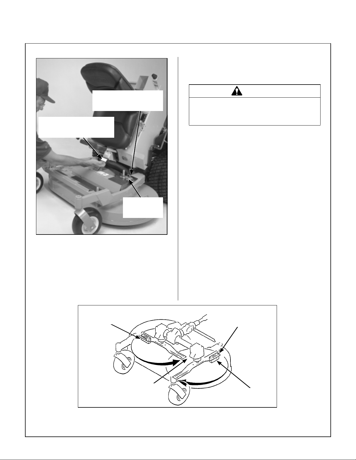
6. Raise the front mower body (instead of lifting
the front of deck) and clip the counterweight
springs to the receptacle on front of body.
Lower the front body to tension the springs.
(Refer to Deck Counterweight Spring Instal-
lation Photo.)
Grease Deck
Support Arms
IMPORTANT: To prevent damage to the mower,
make sure the PTO shaft assembly is securely
locked on the tractor, with the locking balls fully seated in the groove and the ring in the full forward position (refer to the Coupler Ring “Locked” Position
photo). After installation, pull on the shaft to check for
security .
Pull Back Spring-Loaded
Coupler Ring
Installing PTO Quick Coupler
PTO Connection
Arrows on Shaft and Tube
(used to align when sliding together)
Mower Deck Installation (PTO Shaft Connection)
7. With the counterweight springs connected, the
weight on the deck caster wheels should be
15 to 25 Ib (6.8 to 11.3 kg). Check this weight
by lifting on the front of the deck carrier frame.
If required, the spring tension can be adjusted
by tightening or loosening the elastic stop nuts
located underneath the lower spring hook.
Refer to Deck Counterweig ht Spring Inst alla-
tion photo.
1
Page 24
Assembly Instructions
NOTE: A block of wood cut 4 in . (102 mm) high
is a convenient gauge to measure blade height
above ground during the leveling process.
Spring Te nsion Ad justment
Nut Located Under Lower
Spring Hook (Not Visible)
Counterweight Springs Clip
Onto Body With Forward
Body Tilted Up
Hitch Pins
Lock Deck On
Support Arms
Deck Counterweight Spring Installation
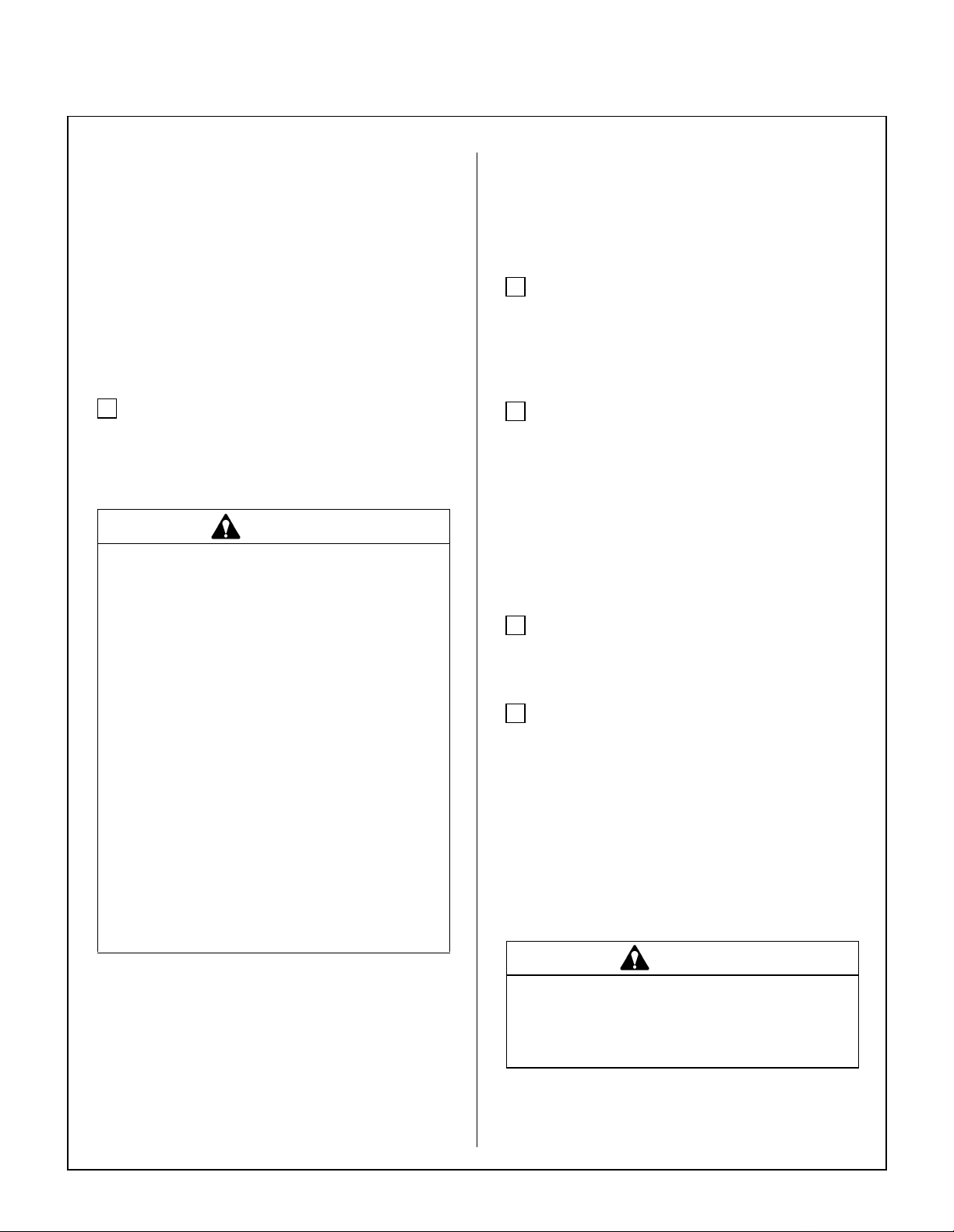
Deck Leveling
1. Position mower on a smooth, level surface. Set
the cutting height to the high est position - 4 in.
(102 mm) - for easy access under the deck to
measure blade height. Re fer to ADJUSTING
CUTTING HEIGHT in Operating Instructions.
WARNING
The machi ne must be shut off du rin g t hi s
procedure.
2. Check the side-to-si de level. Rotate each blade
sideways and measure the distance from blade
tip to ground on each side. If measurements
vary more than 1/8 in. (3 mm), add a washer
shim under the deck support pins on the low side
to level the deck.
3. Check the f ront-to-rear level. Rotate the blades
to po int forw ard. Measure the distance from
blade tip to ground on the front and rea r. The
rear of the blade should be 1/8 to 1/4 in. (3 to 6
mm) higher than the front of the blade; shim the
rear (or front) deck support pins equally to
achieve at least 1/8 in. (3 mm) difference.
NOTE: The mower deck and support frame
are jig wel ded; wit hin nor mal toler ances, very lit tle, if any, shimming should be required to level
the deck. Tire pressure will influence the levelness of the deck. Check the tire pressure as a
possible cause of the deck not being level.
4 in. (102 mm)
Wood Block
Should not vary more
than 1/8 in. (3 mm)
side-to-side
Deck Leveling
0
Should be 1/8 in. (3 mm)
to 1/4 in. (6 mm) higher
at the rear of the blade
4 in. (102 mm)
Wood Block
Page 25
Assembly Instructions
PREOPERATING CHECKLIST
Before operating the mower for the first time, and as
a routine before daily operations, it is important to
make sure the mower is properly prepared and
ready for operation. The following is a list of items to
be checked. (For a mower with frequent operation,
some of these items will not need to be checked every day, but the operator should be aware of the
condition of each.)
For proper fuels and lubricants refer to Specifica-
tions.
FI LL FU E L TANK
Fill the fuel tank using clean, fresh automotive
grade unleaded gasoline (87 octane rating mini-
mum).
DANGER
Handle gasoline with care. Gasoline is
highly flammable and its vapors are explosive. Use safe refueling procedures:
• DO NOT fill fuel tank with the engine run-
ning.
• If the engine is hot, allow to cool before
refueling.
IMPORT ANT: DO NOT mix oil with gasoline. Al-
ways use fresh, automotive grade gasoline. DO
NOT use premium, white, or high-test gasoline. DO
NOT use additives, such as carburetor cleaners, de-
icers, or moisture removing agents. DO NOT use
gasoline blended with methyl alcohol.
CHECK ENGINE CRANKCASE OIL LEVE L
Check the engine crankcase oil level before use and
after each 5 hours of cont inuou s operati on. Ref er
to LUBRICATION for
Oil Level
in Maintenance Instructions.
CHECK AND SERVICE ENGINE AIR CLEAN-
ER SYSTEM
Checking Engine Crankcase
• Check air restriction gauge to make sure there is
no red indication showing.
• Check condition, cleanliness, and security of the
complete air cleaner sy stem (clean primary air
filte r every 100 hours). For detailed proce-
dures, refer to CLEANING the Engine Air
Cleaner System in Main ten a nce Instru ct i on s .
ADJUST CARBURETOR (Initial S tart-up Only)
Refer to ADJUSTMENTS of Carburetor in Mainte-
nance Instructions.
CHECK ENGINE COOLING SYSTEM
• Use an approved fuel container .
• Fue l the mower outdoo rs.
• DO NOT smoke while refueling.
• Avoid spilling fuel; use a funnel or
spout.
• DO NOT overfill the fuel tank; fill up to
about 1 in. (25 mm) below the top of tank.
IMPORTANT: DO NOT perm it dirt or other foreign
matter to enter the fuel tank. Wipe dirt from around
the filler cap before removing. Use a clean fuel storage container and funnel.
Check that the engine cooli ng air intake screen is
free of obstruction by grass clippings or d ebris and
clean if required. Also, cylinder head cooling fins
should be inspected and cleaned if any build-up of
debris is noted [remove two (2) cylinder hea d access panels to inspect and clean].
Check performance of the cooling system by starting the engine, holding a hand adjacent to the cylinder heads, and feeling the cooling airflow.
DANGER
Make sure to keep hands clear of exhaust
pipe, muffler, and moving parts when
checking airflow.
21
Page 26
Assembly Instructions
C H ECK GEAR AX L E OIL LEVE L
Refer to Gear Axle Lubrication in Maintenance In-
structions.
INSPECT FOUR (4) DRIVE BELTS
Engine PTO Drive, Jackshaft Drive, Hydrostatic
Ground Drive, and GHS Blower Drive (if equipped).
CHECK HYDROSTATIC TRANSMISSION OIL
LEVEL
Refer to LUBRICATION for
Transmission Fluid
tions.
CH ECK BATTERY ELECTROLYTE LEVEL
Refer to CHECKING/SERVICING the Battery in
Maintenance Instructions.
CHECK FUNCTIONS OF INSTRUMENT PANEL
AND WARNING HORN
Turn the ignition key to the RUN position. Voltmeter,
Oil Pressure Light, and Warning Horn should all operate, indicating normal function.
CHECK TIRE PRESSURE
Deck Caster Wheel = 20 PSI (137 kPa)
Drive = 15 PSI (103 kPa)
Rear = 20 PSI (137 kPa)
Level
Checking Hydrostatic
in Maintenance Instruc-
Counterweight
Spring Clip
Deck Lift
Rod
Body
Bracket
Deck Secured in UP Position (Non-Tilting)
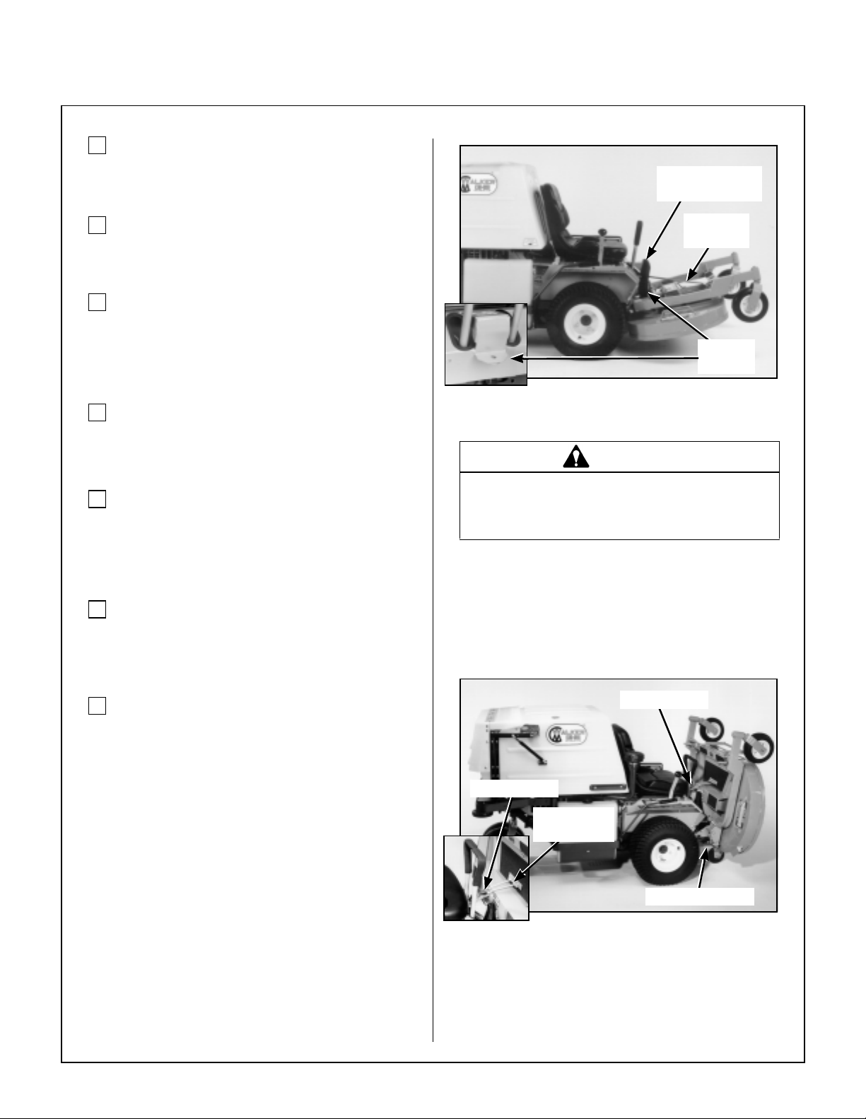
DANGER
Never operate c utter blades w ith deck in
raised position because it is hazardous.
If equipped, the tilt-up deck can be secured in the
raised position by unlocking the deck lock levers on
each side of the carrier frame and inserting the deck
hook into the tilt-up latch on the tractor body . Before
operating the tractor, make sure to re-engage the
deck lock levers after lowering th e deck to the normal operating position.
CHECK AND CLEAN GRASS BUILDUP UN-
DERNEATH MOWER DECK (and inside GHS
blower, if equipped)
Refer to CLEANING the GHS Blower in Mainte-
nance In st ruction s for blower cleaning information.
NOTE: Mower deck is secured in raised position for
cleaning and changing blad es by hookin g the deck
lift rod into the body bracket below the counterweight
spring clip. The rod is hinged and is stowed along the
footrest of the deck carrier frame. A hitch pin on the
end of the rod is used to secure it in pl ace with the
deck raised.
2
Tilt-Up Latch
Tilt-Up Hook
on Deck
Deck Secured in TILT-UP Position
Tilt-Up Latch
Deck Lock Lever
Page 27
Assembly Instructions
3
CAUTION
Do not operate machine with deck tilt-up
pivot joint unlocked.
DANGER
Do not operate the mower with deck in tiltup position. Do not move the tractor with
the deck in the tilt-up position.
CHECK MOWER BLADE CONDITION, SHARP-
NESS, AND SECURITY OF MOUNTING
The blade mounting nut should be tightened to
60 ft-lb (81.3 N⋅m). If blade sharpening is required,
refer to CHECKING/SERVICING for Sharpen
Mower Blades in Maintenance Instructions.
ADJUST MOWER CUTTING HEIGHT, IF RE-
QUIRED
Position the hitch pins in the four deck support pins.
Refer to the “Cutting Hei ght Adjustment” decal on
the deck gearbox cover.
PERFORM ANY ADDITIONAL PROCEDURES
called for on the MAINTENANCE SCHEDULE
CHART in Maintenance Instructions.
2
Page 28
Operating Instructions
CONTROL IDENTIFICATION, LOCATION, AND
FUNCTION
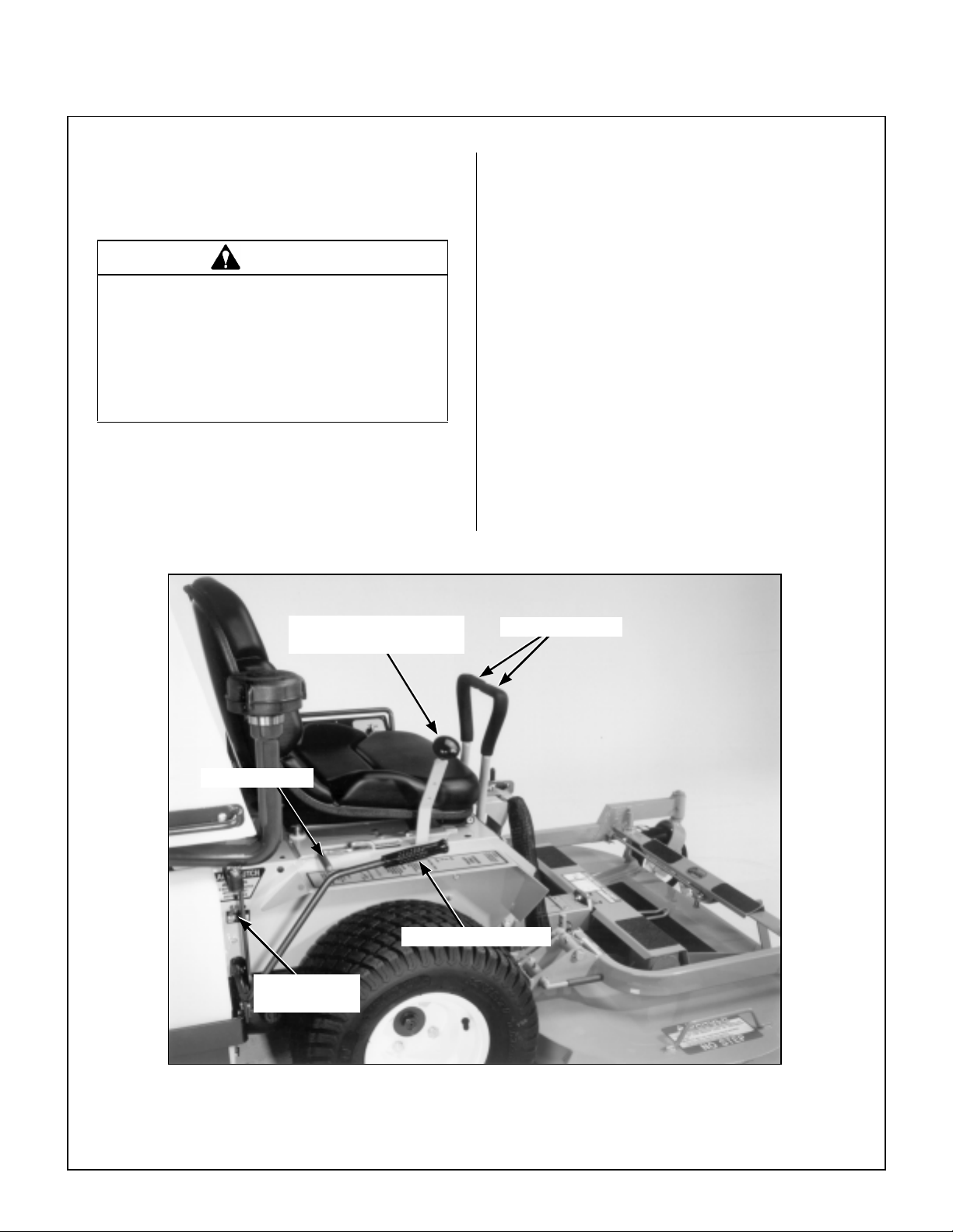
Operating Controls
CAUTION
Before operating the mo wer, become familiar with the location and function of all
operator controls. Knowing the location,
function, and operation of these controls
is important for safe and efficient oper ation of the mower.
Engine Choke
The choke control lever (black knob) is located on
the left side of the seat. To st art a cold engine, move
the choke control forward to the ON position. After
engine starts, move the choke control toward the
OFF position, keepi ng enough choke to allow the
engine to run smoothly as it warms up. As soon as
possible, move the choke to the OFF position. A
warm engine requires little or no choke for starting.
IMPORTANT: Make sure the choke is in the OFF
position during normal engine operation; running
with the choke in the ON po sition CAN damage the
engine.
Parking Brake
Front Body
Latch Release
Forward Speed Control
(FSC)
Blade Clutch (PTO)
Steering Levers
Operating Controls
4
Page 29

Operating Instructions
5
Choke Throttle
Steering Levers
Each drive wheel is controlled by its own independent steering lever, for both steering function and
FORWARD/REVERSE motion. The FSC lever sets
the maximum forward speed, and also sets the forward position of the steering levers. The steering levers operate only with a backward pulling
movement of the lever, which causes the drive
wheel for that lever to first slow down, stop, and then
reverse with a fu ll backward l ever stroke. The levers
are released to the FORW ARD position for “straight-
ahead” ground travel.
Choke and Throttle Location
Engine Throttle
The throttle control lever (red knob) is located on the
left side of the seat and is used to control engine
speed. Moving the lever forward to w a r d th e FAST
position incr eases eng ine speed; moving it back-
ward toward the IDLE position decreases engine
speed.
Forward Speed Control (FSC)
Forward Speed Control (FSC) has two functions:
One is to set forward travel speed, and the other is
to establish the NEUTRAL-PARK position. When
the FSC lever is moved into the FORWARD posi-
tion, a friction lock holds any forward speed setting
from 0 to 5 mph (0 to 8 km/h). The ground speed is
proportional to the lever position; the further the lever is advanced forward, the faster the tractor
moves. It is not necessary to hold the FSC in position since the friction lock maintains the selected lever position. Pulling back on the steering levers
overrides the FSC setting and slows or st ops forward travel. Releasing the steering levers allows
the tractor to resume forward travel at the speed set
by the FSC lever. T o stop and park the machine, the
FSC lever is moved backward to the NEUTRAL-
PARK position.
NOTE: Pushing forward on the steering levers will
not cause any change in tractor motion - there will
be no steering lever reaction and there will be no
machine damage.
Blade Clutch (PTO)
The blade clutch lever has two positions. Pulling the
lever UP en gages the PTO that drives the mower
blades. Pushing the lever DOWN d isengages the
PTO and engages the blade brake.
NOTE: On GHS equipped models, the Powerfil
motor and Grass-Pak® full signal switch are activated by engaging the blade clutch. Refer to Using the
GHS Catcher in this section for a complete description of GHS operation.
Parking Brake
The parking brake functions by locking a pin into the
hydrostatic transmission pinion gear teeth. Moving
the le ver FORWARD engages the parking brake;
moving the lever BACKWARD releases the brake.
IMPORT ANT: Stop the tractor completely before
engaging the parking brake. The parking brake uses
a positive mechanical lock similar to the PARK po-
sition on an autom otive automatic t ransmission. If
the tractor is moving when the brake is eng aged, it
will result in sudden stoppage a nd pos sibl e internal
damage to the axle drive.
®
NOTE: If pressure on the parking brake pin (e.g.
parked on a hill) m ak es i t impos sible to release the
parking brake with the parking brake lever, move the
mower gently forward or backward to release the
pin.
2
Page 30

Operating Instructions
Front Body Latch Release
The front portion of the tractor body hinges forward
for maintenance access and is latched down in the
OPERATING position. To raise the body, move the
latch release forward.
Front Body
Latch Release
Front Bo dy La tc h Re lease
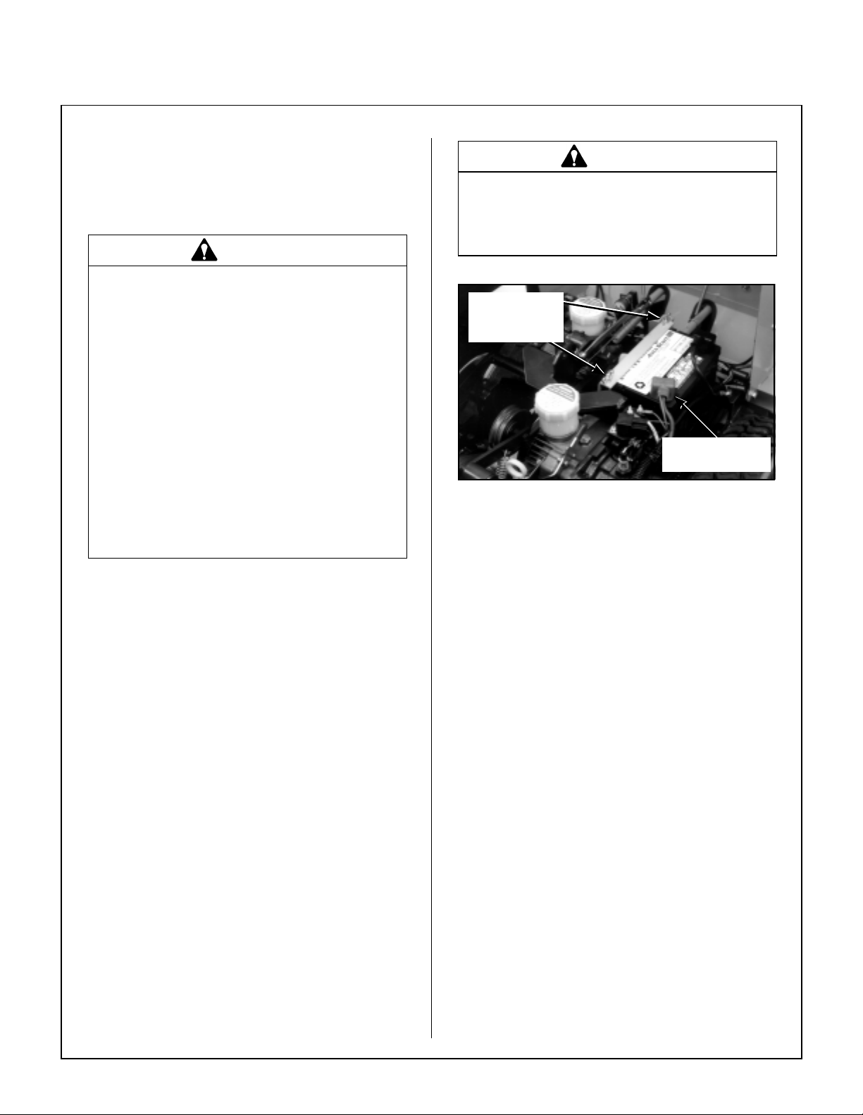
Transmission Lockout Levers
The transmission lockout levers disengage the hy drostatic transmissons. By lifting the lever on top of
the transmission and locking it into place with the
lockout cam, the hydros tatic transmiss ions are released to permit freewheeling. By releasing the cam
and lowe ring the lever, the transmissions are engaged for normal operation. The transmission lever
in the LOCKOUT position is used to enable moving
the machine without the engine running (e.g., for service). Refer to TRANSMISSION LOCKOUT in this
section for operating instructions.
NOTE: The transmission plunger on the side of the
transmission case (activated by the LOCKOUT LE-
VER) must be completely released during operation
of the mower, otherwise operation of t he transmission will be erratic.
Optional Cold Start Lever (Jackshaft Drive Belt Release)
The cold start lever is used for starting the machine
in cold weather [below 40° F (4° C)]. Pulling the lever UP dise ngages the jacks haf t drive belt. When
the jackshaft drive belt is released, the hydrostatic
transmissions are removed from the engine starter
cranking load.
Cold Start Lever
Disengaged
Optional Cold Start Lever
Normal Operating Position
Cold Start Lever
Engaged
Lockout
Levers
Transmission
Plunger
Optional Cold Start Lever
Lockout Lever Location
6
Cold Start Position
Page 31

Operating Instructions
7
The Forward Speed Control also Establishes the Neutral-Park Position of the Steering Levers
LEFT WHEEL
STEERING LEVER
RIGHT WHEEL
STEERING LEVER
FORWARD SPEED
CONTROL LEVER (FSC)
Forward Position
(No Control Change)
Neutral-Park
Position
Reverse Drive
Wheel Motion
Position
Full Forward
Ground Speed
Position
Intermediate
Ground Speed
Position
Neutral-Park
Position
Disengaged
Position
Engaged
Position
Fast
Throttle
Position
Idle
Position
BLADE CLUTCH (PTO)
Pull Up to Engage
Engaged
ON Position
OFF Position
CHOKETHROTTLE
Operating Controls (Top View from Drivers Point of View)
Position
PARKING
BRAKE
Disengaged
Position
2
Page 32

Operating Instructions
Instrume nt P ane l
This illustration shows the configuration of the
switches and indicators located on the instrument
panel.
Hourmeter Voltmeter
Light Switch
(Optional)
Oil Pressure
Warning Light
Over Temperature
Warning Light
Warning
Horn
Ignition
Switch
Instrument Pa ne l
8
Page 33

Operating Instructions
9
Hourmeter
The hourmeter displays operating time accumulated while the ignition switch is in the ON position.
Voltmeter
The voltmeter displays battery and charging system
voltage. An indication of low or high voltage (below
11.5 volts or above 15.5 volts) indicates an electri-
cal system failure. The cause of the failure should
be determined and corrected.
Oil Pressure Warning Light
The oil pressure warnin g li ght ind icates that engin e
oil pressure is below the safe operating range [below
3 to 5 PSI (21 to 34 kPa)]. This light (and warning
horn) will come on when the ignition is turned ON, but
should go off after th e eng ine is s tarted. I f the l ight
fails to come on when the ignition switch is turned ON,
it could indicate a burned out bulb. If the light comes
on during engine o peration, st op the engine imm ediately and correct the source of the problem before
further engine operation.
Ignition Switch
The ignition switch is used to start and stop the engine. The switch has three positions: “O” is the OFF
position, RUN is the position the key returns to after
starting, and “S” is the START position. When starting the engine, turn the key clockwise to the “S” position. Do not hold the key in the “S” position longer
than 10 seconds. If the engine does not start, return
the key to the “O” position for at least 60 seconds before making a restart attemp t. Prolonged cranking
can damage the starter motor and shorten battery
life. Release the key when the engine starts, and it
will return to the “RUN” position. To stop the engine,
rotate the key counterclockwise to the “O” position.
OFF
ON
IMPORTANT: Continued operation of the engine
with an illu minated oil pre ssure warning li ght MAY
cause severe engine damage (if a low oil pressure
condition exists).
Over Temperature Warning Light
The over temperature warning light indicates that
engine oil temperature and/or cylinder head temperature are above the safe operating limit and the en-
gine is ov erhea ting [above 3 05° F (152° C) oil or
450° F (232° C) cylinder head ]. If this light comes
on, there may be a problem with:
• Engine cooling system (material pack ed into cyl-
inder head cooling fins, clogged air int ake screen)
• Low oil level in crankcase
Stop the engine and correct the source of the problem before further operation.
IMPORTANT: Continued operation of the engine
with an illuminated over tempe rature warnin g light
MAY cause severe engine damage (if a high oil temperature or head temperature condition exists).
START
Ignit ion Swit c h
Light Switch (For Optional Lights)
Operates headlights (when installed).
Warning Horn
The warning horn sounds t o alert t he operator that
an unsafe engine condition is being indicated when engine temperature is too high or engine oil
pressure is too low. If the horn sounds, check the
indicator lights and correct the problem before further operation.
2
Page 34

Operating Instructions
STARTING THE ENGINE
CAUTION
Before operating the mower, read and understand all Safety Instructions and Operat-
ing Instructions.
WARNING
NEVER run the engine in an enclosed or
poorly ventilated area. Engine exhaust
contains carbon monoxide, an odorless
and deadly gas.
1. Before attempting to start the engine, make
sure the operator is in the seat, the Forward
Speed Control is in NEUTRAL-PARK position,
and the blade clutch and parking brake are
DISENGAGED.
Cold Start
Lever Engaged
Optional Cold Start Lever
2. Move the choke lever to the ON position and
move the throttle 1/4 to 1/2 open (toward
FAST). Turn the ignition s witch t o the S TART
position to start the engine. Release the key to
RUN position as soon as the engine starts.
NOTE: Release parking brak e to prev ent extra
load on the starter if the transmission neutral is
slightly out of adjustment.
CAUTION
A safety interlock switch system PREVENTS CRANKING the engine with either
the Forward Speed Control or the b lade
clutch ( PTO) ou t of ne utra l. If t he eng ine
cranks otherwise, the safety system is not
working and should be repaired or adjusted before operating the mower. DO
NOT disconnect safety switches; they are
for the operator’s protection.
NOTE: For s tarting in cold weather [below 40° F
(4° C)], use the optional cold start lever to release
the jackshaft drive belt and remove the hydros tatic
transmission from t he starter cranking load. After
the engine has b een s tarted and warmed up, lower
the lever to re-engage the jackshaft drive belt.
NOTE: The choke may not be required if the
engine is warm.
IMPORTANT: If the engine fails to start after
approximately 10 seconds of cranking, the engine should be checked before furt her cranking.
Turn the key to the OFF position and allow a
60 second cool-down period between starting
attempts. Failure to follow these guidelines can
damage the starter motor and shorten battery
life.
3. After the engine starts, make sure the oil pressure light goes off. If not, stop the engine immediately and find the cause of the problem. Make
sure the oil pressure light is off prior to engaging
the mower blades and beginning operation.
4. Gradually move the choke to the OFF position,
keeping enough cho ke on to allow the engine
to run smoothly as it warms up. As soon as
possible, move the choke to the OFF position.
0
Page 35

Operating Instructions
IMPORTANT: M ake sure the chok e is in the OFF
position during normal engine operation; running
with the choke in the ON position CAN damage the
engine.
ADJUSTING GROUND SPEED AND STEERING
IMPORTANT: If the DSD52 or DSD62 Mower
deck is installed on the tractor, make sure the dolly
wheel is retracted BEFORE moving.
CAUTION
Learn to START, STOP, and MANEUVER
the mower in a large, open area.
If the operator has not operated a machine with LEVER STEERING OR DUAL
HYDROSTATIC TRANSMISSIONS, steering and ground operation should be
learned and practiced until the operator is
completely comfortable handling the machine BEFORE ATTEMPTING TO MOW.
DANGER
Keep feet on foo trests all times w hen th e
machine is moving.
Beginning Recommendations are:
♦ Learn operation of the mower in an open
area away from buildings, fences, and ob structi ons. Learn ope ration on f lat ground
BEFORE operating on slopes.
♦ Start maneuvering the mower with SLOW
engine speed and SLOW Forward Speed
Control setting until familiar with all operating characteristics.
♦ Remember it is not necessary to hold the
steering levers forward (a unique Walker
feature); always PULL on the levers for
steering or for reverse motion of the mower.
♦ Learn to operate the mower with your left
hand on the s teering levers and right h and
on Forward Speed Control. The use of two
hands on the steering levers tends to cause
overcontrol.
♦ Learn to operate the steering lever s with
smooth action. Jerky movements are hard
on the transmission and lawn. For sharp
turns, do not allow the inside wheel to stop
and twist on the grass. Pull the steering lever controlling the inside wheel into reverse
for a smooth “ rolling” turn (one wh eel rolling forward while the other rolls back ward ).
1. Move the FSC out of NEUTRAL-PARK position
to the desired forward speed. DO NOT hold forward on steering levers. It i s not necess ary to
hold the FSC lever in position since a friction
lock maintains the selected lever position (and
forward travel speed).
NOTE: If the FSC lever will not stay in the
selected position, the friction lock needs to be
adjusted. Refer to ADJUST MENTS of Forward
Speed Control Friction Lock in Maintenance
Instructions.
2. Steer by pulling the lever on the side of desired
direction of turn, e.g. , pull the LH le ver to turn
left. To minim ize the p ossib ility o f overc ontr ol,
use only one hand on both steering levers.
♦ Practice maneuvering the mower until
you can make it go exactl y where you are
aiming.
♦ Remember, for an emergency stop, or in
case of loss of control, machine m ovement
can always be stopped quickly by pulling
the Forward Speed Control into the NEUTRAL-PARK position.
31
Page 36

Operating Instructions
Pull Steering
Levers With
Left Hand
Forward Speed Control
(FSC)
Keep Feet On Footrest
When Moving
Correct Operator Hand Position
on the Controls
3. Reverse direction of the mower by pulling both
levers backward.
NOTE: Smooth action on the steering levers
will produce smooth mower ope ration. Remember to keep the engine and ground speed slow
until learning the control response.
4. The FSC may be adjusted forward for faster
ground speed and ba ckward for slower ground
speed. When mowing, ground speed should be
adjusted to match the load on the cutter blades,
i.e., as the engine pul ls down in he avy cutting,
pull back on the FSC lever t o reduce ground
speed. Adjusting ground speed helps maintain
a balance between engine power and blade
speed for high-quality cutting action.
5. Stop ground travel by pulling both steering levers backward to the NEUTRAL position (tractor not moving) and then moving the FSC lever
to the NEUTRAL-PARK posit ion.
NOTE: If the tractor creeps forward or backward with the FSC lever in the NEUTRAL-P ARK
position, the transmission control needs to be
adjusted. Refer to ADJUSTMENTS of Trans-
mission Control in Maintenan ce Instru ct io ns .
ENGAGING THE MOWER
1. Set the engine throttle at about 1/3 speed. Do
not attempt to engage the blade clutch at
high engine speeds. This will dras tical ly sho rt-
en drive belt life. Use only moderate engine
speed when engaging the blade clutch.
2. Pull the blade clutch lever SLOWLY up to en-
gage the mower blades.
CAUTION
A safety interlock switch (seat switch) will
cause the engine to stop if the blade
clutch is engaged an d the operator i s no t
in the seat. The function of this switch
should be checke d by the operator raising off the seat and engaging the blade
clutch; the engine should stop. If the
switch is not working, it should be repaired or replaced before operating the
mower. DO NOT disconnect the safety
switches; they are for the operator ’s protection.
IMPORTANT: DO NOT engage the blade clutch
when transporting the mower across drives, sidewalks, loose materials, etc. DO NOT engage the
blade clutch with the PTO shaft disconnected
(the mower deck removed from tractor).
CAUTION
If the cutting blades strike a stationary object while mowing, stop the mower immediately, disconnect the spark plug wires,
lift the deck, and inspect the deck and
blades thoroughly for damage. Make sure
that the blade timing has not been disturbed (the blades should be at 90 degrees
to each other). Refer to REPLACING/REPAIRING the Blade Overload Shear Bolts
in Maintenance Instructions if blades are out
of time. Also, make sure the blade retaining nuts are torqued to 60 ft-lb (81.3 N⋅m).
2
Page 37

Operating Instructions
3
Engaged
Position
Blade Clut ch E ngaged
IMPORTANT: DO NOT disengage the blade
clutch with high engine speed (above 1/2 throttle) since the bra ke action on the bl ade dri ve will
cause premature wear of the brak e band.
WARNING
A brake stops the cutter blades (and blower on GHS equipped models) from freewheeling within five (5) seconds after
disengaging the clutch. If the brake system malfunctions and the blades do not
stop within five (5) seconds, the brake
should be adjusted or repaired before operating the mower. Refer to ADJUSTMENTS of Blade Clutch (PTO) in
Maintenance Instructions.
4. Turn the ignition switch OFF. When stopping
the engine, do not reduce the throttle below 1/2
speed. Since the engine is equipped with a
shutdown solenoid, stopping at low idle may
cause engine run-on or backfiring.
Disengaged
Position
Blade Clutch Disengaged
STOPPING THE MACHINE
1. Slow the engine to a fast idle; put the throttle in
the 1/2 throttle position.
2. Pull the steering levers to the NEUTRAL position and then mo ve t he F SC lever b ac kward t o
the NEUTRAL-PARK position.
3. Disengage the blade clutch.
WARNING
Remove the key from the ignition switch
when leaving the mower unattended. This
will prevent children and inexperienced
operators from s tarting the e ngi ne.
5. Engage the parking brake.
IMPORTANT: The hydrostatic transmissions
lock to prevent the mower from rolling f reely with
the engine stopped. However, if the mower is
parked on a slope, it is necessary to ENGAGE
the parking BRAKE to prevent the mower from
creeping. This is due to a small amount of slippage in the hydrost atic transmissions, especial ly
when transmissio n flui d is warm.
3
Page 38

Operating Instructions
ADJUSTING CUTTING HEIGHT
WARNING
The engine must be stopped before adjusting cutting height. Disengage the
blade clutch (PTO), stop the engi ne, and
remove the ignition key . Wait for all movement to stop before getting off the seat.
Cutting height is adjusted by positioning the four retainer hitch pins in a series of seven vertical holes on
the deck support pins. Lift handles have been provided on each end of the deck to assist in raising the
deck while positioning the hitch pins. Cutting
heights range from 1 in. (25 mm) [top holes] to 4 in.
(102 mm) [bottom hol es] in 1/2 in. (13 mm) increments.
Lift Handle
Deck Support
Pin
3. The mower will “freewheel” with the levers in the
LOCKOUT position. The levers must be in the
highest position to completely unlock the transmissions.
Lockout Lever
Plunger
Depressed
Lockout Lever - Freewheel Position
4. After moving the mower, release the locking
cam, placing the lever DOWN in the normal
OPERATING position. Make sure the transmission lockout plunger on the side of the t ransmission case (activated by t he lo ckout le ve r) is
completely released, otherwise the t ransmission operation will be erratic.
Cam in
LOCKOUT
Position
Lockout Lever
Hitch Pin
Cutting Height Adjustment
TRANSMISSION LOCKOUT
To mo ve the mower w ith th e engin e NOT running
(dead battery, maintenance, etc.), the hydrostatic
transmissions are unlocked (released).
1. Raise the front body.
2. Lift the transmission lockout lever on both the
RH and LH transmissions and secure into place
with the lo cking cam.
4
Plunger
Released
Lockout Lever - Normal Operating Position
Cam in
UNLOCKED
Position
Page 39

Operating Instructions
5
RECOMMENDATIONS FOR MOWING
IMPORTANT: Operate the engine at full speed
when mowing, to allow the engine to produce full
horsepower and to increase efficiency of the engine
cooling system.
• Keep the mower deck and discharge chute clean.
• Mow with sharp blades. A dull blade tears the
grass (resulting in poor lawn appearance) and uses
extra power (slowing the mowing speed).
• It is preferable to cut grass when it is dry and not
too tall. Mow frequently and do not cut grass too
short. (For best appearance, cut off 1/3 or less of
existing grass height.)
• When mowing, operate the engine at or near full
throttle for the best cutting action and performance
of the grass handling system (GHS). Mowing with a
lower engine RPM causes the mowing blade to not
cut clean and tear the grass. The engine is designed
to be operated at full speed.
• When mowing in adverse conditions (tall and/or
wet grass), mow the grass twice. Raise the mower to
the highest setting - 4 in. (102 mm) - for the first pass
and then make a second pass cutting to the desired
height.
• When using a side discharge mower deck, the
side discharge shield must not be removed and
must be kept in the lowest possible position to
deflect grass clippings and thrown objects downward. Orient the side discharge away from sidewalks or streets to minimize cleanup of clippings.
When mowing close to obstacles, orient the side discharge away from obstacles to reduce the chance of
damage to property by thrown objects.
Side Discharge Shield in Lowest Position
• When operating on a slope, red uce speed and
use caution to start, stop, and maneuver. Avoid
sharp turns or sudden changes in direction. The
maximum recommended side slope operating
angle is 20 degrees or 33% grade.
• Use a slow setting on the FSC for trimming
operations.
• Make sure the mower is leveled properly for a
smooth cut. Refer to
Instructions.
Deck Leveling
in Assembly
• Use an alternating stripe mowing pattern for
best appearance and vary the direction of the stripe
each time the grass is mowed to avoid wear patterns
in the grass.
• Avoid damage to the grass by slipping and skid-
ding of the drive tires. Use smoo th control mo vements of the steering levers since the hydrostatic
transmissions are “power boosted controls” and jerking the levers can easily slip the tires. For sharp
turns, do not allow the inside wheel to stop and twist
on grass; pull inside steering lever into reverse for a
smooth “rolling” turn (one wheel rolling forward while
the other rolls backward).
Maximum Recommended
Side Slope - Do Not Operate
on Steep Slopes
Maximum Recommend ed Side Slope
3
Page 40

Operating Instructions
RECOMMENDATIONS FOR TILT-UP DECK
OPERATION/TRANSPORT
To avoid potential deck and/or tractor damage while
using the tilt-up deck, the following recommendations are offered:
• Do not move the tractor with the deck in the tilt-
up position since both the roller wheels (on the back
of the deck) and the GHS discharge chute m ay be
damaged by moving the tractor. The tilt-up configuration should only be used when the tractor is
parked.
• The tractor body should never be tilted for-
ward with the deck in the tilt-up position. This can
cause the deck to unhook from the tracto r and fall
with considerable force, potentially c ausing dec k or
tractor damage and/or bodily injury.
• When transporting a tractor with the deck in th e
tilt-up position (on a truck or trailer), the deck
should be s ecured to the vehicle with a strap or
rope (stop vertical movement). This will prevent the
deck from bouncing on the rear roller wheels (causing breakage). This will also prevent the dec k from
unhooking from the tractor and falling, potentially
causing deck or tractor damage. Damage to other
items parked in front of the deck may also occur.
6
Page 41

Operating Instructions
7
GRASS HANDLING SYSTEM (GHS)
GHS Mode l On ly
Powerfil
Drive Motor
Actuator
Rod
“Full” Signal
Horn
®
Grass-Pak
Vane Switch
Catcher Door
Safety Latch
®
Exhaust Screen
(Removable)
Exhaust
Deflector
PTO and Blade
Gear Drive
Rear Discharge
Mower Deck
Delivery
Chute
PTO
Clutch
Body Chute
Blower
Deck
Discharge Chute
Dump Handle
Powerfil
Delivery Spout
Assembly
Catcher
Door
Catcher
Door Spring
Grass Catcher
®
GHS Flow and Components
3
Page 42

Operating Instructions
Gene r al Info r m a t ion
The Grass Handling System (GHS) consists of a
rear discharge mower deck connected to a 10 in.
(25 cm) blower and a rear mounted grass catcher
with 7.0 bushel (246 liters) capacity or optional 9.5
bushel (335 liters) capacity. The GHS blower operates any time the mower blade clutch is engaged
and moves grass through the rear discharge deck
chute into the grass catcher. Blower airflow is exhausted out the back of the grass catcher, through a
filtering screen. When the grass c atch er i s f ull and
needs to be emptied, a “full” signal horn alerts
the operator. When the “full” signal horn sounds, it
is important to stop mowing to prevent overfilling
and clogging of the blower system.
IMPORTANT: N ormally, the GHS blower operates
with no maintenance or cleaning required. However, under certain operating conditions, the inside
of the blower housing may accumulate a deposit of
dirt, c ausi ng wear an d bi ndi ng of the bl owe r whee l.
Normall y, dirt buil dup occu rs wh en mow in g a com-
bination of dirty and damp grass, especially in
the springtime. When operating in these conditions, check the blower wheel frequently for
binding and clean the blower housing as required.
Refer to CLEANING the GHS Blower in Mainte-
nance In st ruction s.
NOTE: In Autu mn, when usin g the GH S mower to
vacuum leaves, it is recommended to raise the
front of the mower deck 2 to 3 notches [1 to 1-1/2
in. (25 to 38 mm)] higher than the rear. This wil l
avoid “bulldozing” leaves, particularly when the
leaves are piled in a thick layer. To make this adjustment, the hitch pins in the two (2) front deck
support pins are re positioned 2 t o 3 notches higher
while leaving the rear pins in their original position.
DANGER
NEVER operate the GHS catcher with the
back door open. Objects may be thrown
out the back of the catcher with sufficient
force to cause seriou s injury to bystanders or pr operty dam age.
NOTE: Wh en a side discharge or m ulching mow-
er deck is installed on the GHS model, a blower
intake cover should be installed in the blower intake
tube. This cover “unloads” the blower and seals
the intake to effectively eliminate power loss and
blower noise when the blower is not being used.
Blower
Intake Cover
Blower Intake Cover
DANGER
ROTATING BLOWER BLADES
NEVER operate the GHS blow er with the
blower discharge chute uncovered (grass
catcher in the dump po sition) since dangerous projectiles may be thrown. NEVER
put hands into the bl ower di schar ge c hute
for any reason. Use a stick or similar instrument to remove any ma terial if clogging has occurred.
CAUTION
NEVER leave grass clippings in the grass
catcher after mowing. Damp clippings
generate heat as they decompose. This
MAY cause spontaneous combustion.
8
Page 43

Operating Instructions
9
Clogging Checklist In case of clog ging, there w ill be a distinct change
in the sound of the blower, i.e., the blower sound
will stop. Also, the mower deck will begin to leave a
trail of grass clippings. When this occurs, stop the
engine, disconnect the spark plug wires, and make
sure all movement has stopped before attempting to uncl og.
DANGER
NEVER place hands under the mower deck
or in the GHS blower discharge chute. Use
a stick or similar tool to remove any
clogged material.
Normally, any clogging w ill fir s t de v elop at the ba c k
of the mower deck in the discharge opening into the
blower chute. Clogging at this point does not indi-
cate a particular problem in this part of the
system, but is a symptom of something restricting the flow of material throughout the entire
system. The following list of items should be
checked if a pattern of clogging begins to develop.
All of these items are capable of causing clogging at
the back of the deck.
• Check to see if the RH and LH mower blades are
installed for the correct rotation - install blades so
the cutting edges move toward each other.
Blades Must Operate at
Right Angles (90 Degrees)
FORWARD
• Check the amount of flat section remaining at
blade tip. This is the area that is ground a way (removed) when the blades are sharpened. If too much
of the flat section is removed, the “air lift” performance or “shovel” effect of the blade deteriorates to
the point that discharge of grass clippings into the
blower chute is marginal. Replace cutter blades if
less than 3/4 in. (19 mm) flat section remains at the
blade tip.
• Check that the interior of the deck housing and
baffling is reasonably clean and free of grass and
dirt buildup. While some degree of material buildup
can be tolerated, a point is finally reached where the
flow of air and grass clippings is restricted.
NOTE: One condition that quickly causes a
buildup of material in the deck housin g is mowing
grass and/or weeds which are “juicy.” The material
collects under the deck with sticky , green juice. Clover and weeds are especially a problem. The mower deck will need to be cleaned frequently when operating in these conditions.
• Check the deck cutting height setting. When
working in thick, tall grass, lower deck settings
[1 to 2 in. (25 to 51 mm ) cu tting he ights] tend to
restrict airflow from moving into and under the
deck. Raising the deck cutting height will significantly increase airflow an d reduce clogging when
working in thick, tall grass .
• Check the interior of the chute connecting the
mower deck to the blower for smoothness and
freedom f rom ob s truction.
• Check the blower wheel for bent blades and
excessive clearance between the blade tip and the
blower housing. A clearance greater than 1/8 in.
(3 mm) will cause a significant loss of blower
performance.
• Check the blower discharge chute into the gras s
catcher for smoothness and freedom from obstruction.
Mounting Nut
Rear Discharge
Chute
Blade Rotation for GHS Mower Deck
(view from underneath)
Torque = 60 ft-lb
(81.3 N
⋅m)
• Check the elbow inside the grass catcher for a
buildup of material in the ra d iu s of the elbow. In
certain conditions (damp/dirty grass) a considerable “clump” of material can accumulate at this point,
greatly restricting material and airflow.
3
Page 44

Operating Instructions
• Check that the openings in the removable ai r
exhaust screen in the grass catcher are not
plugged. If the screen is clogged, refer t o Cleaning
the GHS Exhaust Screen in th is section.
Remember, anything that restri cts airflow or m aterial
flow along the entire path from the m ower deck to
the grass catcher can cause clogging.
Using the Tilt-Up Deck Refer to CLEANING of Grass Buildup in Mower
Housing for
Instructions.
Using the GHS Catcher
Powerfil
The GHS catcher has an oscillating grass delivery
spout (P OWERFIL
grass clippings throughout t he interior of the gras s
catcher (even when mowing wet, heavy grass). The
oscillati ng act ion m ay be c heck ed by tu rning the
ignition switch to the ON posit io n an d movi ng the
blade clutch to the ENGAGED position. The spout
should oscillate approximately 25 cycles per
minute.
NOTE: If the grass spout fails to oscillate, the clutch
switch should be chec ked for function (the switch
closure is adjustable).
®
“Full” Signal Horn
The GHS cat cher has a “full” signal horn to alert
the operator to dump the catcher when it is full (to
prevent overfilling and clogging) . The “full” signal
horn is activated by a vane switch (Grass-Pak
switch) mounted on the grass delivery spout. Oscillating action of the spout triggers the vane switch as
grass begins to fill in around the spout when the
catcher is almost full.
The “full” signal function may be checked by turning
the ignition swi tch ON, engaging the blade clutch
(engine not running), opening the catcher back door,
and triggering the Grass-Pak
oscillates. The ho rn shoul d sound a s the s witch is
moved in both directions.
Tilt-Up Decks
®
) which is designed to spread
in Maintenance
®
vane by hand as it
WARNING
DO NOT test the Grass-Pak® switch with
the engine running. Projectiles may be
thrown out of the grass delivery spout,
and COULD cause serious injury.
The “full” signal horn is designed to operate (sound)
when the grass catcher is almost full. The t iming of
the signal is ad justable by changing the position of
the vane on the G rass-Pak
coming on too soon (catcher not complete ly full) or
too late (grass clogging in catcher spout and delivery chute), refer to ADJUSTMENT S of GHS “Full”
Signal Horn in Maintenance Instructions.
NOTE: The horn signal should be adjusted to
sound BEFORE the catcher is completely full to
give the operator time to react and stop mowing. A n
indication the horn signal is coming on too late (delayed too much) is if grass clippings are falling out of
the grass catcher delivery chute when the catcher is
dumped.
Cleaning the GHS Exhaust Screen
To remove the grass catcher screen for cleaning,
open the catcher door, push forward and pull down
on the grass catcher screen knobs (on either side of
the screen), and slide the s creen out. Use a high
pressure washer or water spray and brush to clean
the screen.
Keeping the catcher exhaust screen clean and open
is essential to good performance of the catching
®
system. In some mowing con ditions, e.g., wet and
dirty, it will be necessary to clean the screen frequently to avoid clogging the m ower deck, blower,
and chutes due to airflow restriction.
Grass Catcher
Screen
®
switch. If the signal is
Removal
Knobs
Grass Catcher Screen Removal for Cleaning
0
Page 45

Operating Instructions
Dumping the Catcher
For dumping, the catcher e ith er tailgate dum ps int o
a disposal area or dumps into the optional dump
bag. The dump bag is a reusable nylon f abric ba g
designed to conveniently move grass clippings from
the catcher to a remote disposal area or container.
Tailga te Du m p ing
1. Open the back door by lifti ng on th e door handle.
NOTE: To prevent accidental door closure, a
safety latch locks the door open in the fully
opened position while the catcher is being
dumped.
2. Tilt the catcher back to dump by lifting on the
catcher lift handle on the low er front corner o f
the catcher.
3. Lower the catcher smoothly down to the normal
operating position. DO NOT allow the catcher
to drop down - the gas spring, that holds the
catcher in the raised position, is not a shock
absorber for lowering the catcher.
4. Close the door by holding the door handle
with the left hand and releasing the safety
latch on the door hinge mechanism with the
right hand. The safety latch is released by
pressing in on the top of the latch. Then,
smoothly close the door, working against the
spring pressure that holds the door closed.
DO NOT let the door slam shut by releasing
the do or bef ore it is c l osed.
Safety
Latch
Catcher Door Safety Latch
Using the Dump Bag (7.0 Bushel Catcher)
1. Open the back door by l ifting on the door ha ndle.
NOTE: To prev ent accidental door closure,
a safety latch locks the door open in the
fully opened position while the catcher is being dumped.
2. Orient the dump bag with one of the handle
straps on the bag opening facing up.
Tailgate Door
Handle
DANGER
PINCH POINT - SPRING LOADED DOOR
When lowering the door on the GHS
catcher, depress the safety latch on the
side of the catcher. BE VERY CAREFUL to
keep ha nds, finge rs, etc. ou t of the h inging mechanism and away from the door
frame as the door closes. The springs that
hold the door closed during operation are
very powerful, and the door can slam shut
with considerable force.
Hook Bag
on Bumper
Positioni ng Dump Bag on Ca tc her
41
Page 46

Operating Instructions
3. Hook the bottom of the bag over the rear
bumper while lifting on the handle strap.
DANGER
4. Tilt the catcher back to dump into the bag by lifting on the catcher lift handle on the lower
front corner of the catcher with the one hand
while continuing to ho ld up o n the bag stra p
with the other han d. Refer to photos for positioning the bag and dumping.
Catcher Lift/
Dump Handle
Dumping Catcher into Dump Bag
PINCH POINT - SPRING LOADED DOOR
When lowering the door on the GHS
catcher, depress the safety latch on the
side of the catcher. BE VERY CAREFUL
to keep hands, fingers, etc. out of the
hinging mechanism and away from the
door frame as the door closes. The
springs that hold th e door closed d uring
operation are very powerful, and the door
can slam shut with considerable force.
Power Dump Option
When equipped with the optional p ower dump system, the operator dumps the catcher while sitting in
the seat. A toggle switch operating a power ram is
used to raise and lower the catcher. The back door
automatically opens and closes during the dump
cycle.
Hold the toggle switch UP or DOWN to RAISE or
LOWER the catcher. When the catcher reaches the
full raised or lowered position, the power ram clutch
will make a ratcheting sound. Rel ease the toggle
switch as soon as this sound is heard. DO NOT op-
erate the ram with the clutch ratcheting for an
extended time as t his wi ll cause ex tra wear on the
clutch mechanism.
5. Lower the catcher smoothly down to the normal
CAUTION
operating position. DO NOT allow the catcher
to drop down - the gas spring, that holds the
catcher in the raised position, is not a shock
absorber for lowering the catcher.
6. Clos e th e door b y hol din g the do or ha ndl e w ith
the left hand and releasing the safety latch on
the door hi nge mech ani sm w ith t he ri ght ha nd.
The safety latch is released by pressing in on
the top of the latch. Then, smoo thly close the
door, working against the spring pressure that
holds the door closed. DO NOT let the door
slam shut by releasing the door before it is
closed.
2
The operator should be in the seat and
bystanders stay clear when the power
dump is operating. The power dump is
used ON LY for tai lgate dum ping. Do no t
attempt to use the optional dump bag or
any other ba g wi th th e power dump.
NOTE: If grass tends to hang up in the catcher af-
ter raising the catcher with the power dump, “jiggle”
the steering levers and make the tractor bounce a little to unstick the grass and make it sli de out of the
catcher.
NOTE: With the power dump mechanism in the
normal operating position (catcher down), the
catcher can be manually ra ised for access to the
engine and the catcher can be manually du m pe d .
Page 47

Operating Instructions
3
Cable Guide
Lift Channel
Power Dump
Ram Actuator
Grass Catcher
Door Actuator
Arm
Catcher Door
Gas Sp ring
Fork
Catcher Door
Cable Rod
Guide
Cable Assembly
Gas
Spring
Actuator Mount
Assembly
Dog Leg
Assembly
Rubber
Bumper
Power Dump Components
4
Page 48

Maintenance Instructions
CAUTION
Mainten ance proced ures requiring s pecial training or
tools should be performed by a trained technician .
MAINTENANCE SCHEDULE CHART - RECOMMENDED SERVICE INTERVALS - MODEL MT
Service Item
Check Engine Crankcase Oil Level x 46
Check/Clean Engine Air Cooling System* x 57
Check Security of Air Filtration Components x 60
Check Air Filter Restriction Gauge x 54
Clean Grass Buildup Under Deck x 58
Clean GHS Exhaust Screen* x 40
Clean GHS Blower* x 59
Service Mower Blades x 61
Check Functions of Instrument Panel and
Warning Horn
Lubricate Grease Fittings and Oil Points* x 47
Check PTO Gearbox Oil Level** x 51
Check Battery Electrolyte Level x 60
Check Hydrostatic Transmission Fluid x 52
Check Tire Pressure x 61
Check Drive Belts (Jackshaft, Engine PTO,
GHS Blower, Ground Drive)
Check Gearbox Oil Seals x 63
Check Turbine Precleaner* x 54
Check/Clean Primary Air Filter Element
Change Engine Crankcase Oil
Check/Adjust Blade Clutch (PTO)/
Brake Action
Check Oil Level in Gear Axle x 51
Clean Hydrostatic Transmission Cooling Fins x 60
Clean Engine Cooling Fins x 57
Check/Regap Spark Plugs x 63
Change Engine Oil Filter x 46
Check Fuel Lines and Clamps x 63
Check/Clean Secondary Air
Filter Element and Foam Precleaner
Replace Primary Air Filter Element
and Vacuator™ Valve
Replace Fuel Filter x69
Service Battery x60
Check/Adjust FSC Friction Lock x 79
Service Solenoid Shift Starter x 63
Change Gear Axle Oil
Change Hydrostatic Transmission Fluid
Replace Fuel Lines and Clamps x63
∆
∆∆∆
∆∆
∆
∆
∆∆∆
Daily
x22
25
Hours
x62
100
Hours
x54
x46
x74
200
Hours Yearly
x56
x54
Every
2Years
x51
x52
Ref.
Page
∗ More often in extremely dusty or dirty conditions (refer to notes about air cleaner element in
IMPORTANT TIPS FOR CARE OF KOHLER ENGINE)
∗∗ Change PTO gearbox oil after first 100 hours of operation (break-in period)
∆ Primary air cleaner is remote mounted Donaldson Radialseal™ unit, secondary air cleaner is
standard Kohler engine mounted unit, replace primary filter every year or after 6 cleanings
∆∆ Change engine oil and filter after first 5 hours of operation of a new engine (break-in period)
∆∆∆ Change every 2 years or 1000 hours
4
Page 49

Maintenance Instructions KOHLER TIPS
5
IMPORTANT TIPS FOR CARE OF THE KOHLER
ENGINE
Fuel System
• Fuel must be clean - free from water, dirt, and or-
ganic material.
• Change fuel filter on a regular basis and when
contamination is suspected or found in the fuel.
Starting/Stoppi ng
• For starting in cold weather [below 40° F (4° C)],
use the optional cold start lever to release the hydrostatic transmissions from the starter cranking load.
• Start engine with the throttle advanced off idle
(1/4 to 1/2 throttle). This will aid starting, especially
in cold weather.
• Keep the battery fully charged.
• Match crankcase oil viscosity to the ambient tem-
perature, allowing the engine to crank faster and
start easier.
• Use fast idle for stopping engine to avoid run-on
or backfiring.
Cooling System
• Keep engine air intake screen and cylinder head
fins free of grass clippings, chaff, and dirt. Inspect
intake screen and cooling fins for cleanliness and no
damage.
• Periodically remove two access panels in the en-
gine shroud to inspect and clean cylinder head cooling fins.
• Check performance of the cooling system by
starting the engine, holding a hand a djacent to the
cylinder head, and feeling the cooling airflow.
• Operate the engine at full speed when mowing.
This allows the engine to produce full horsepower
and move more cooling air through the engine cooling fins.
Air Cleaner System
• Use only Kohler and Donaldson air cleaner ele-
ments. Aftermarket elements may not seal in the air
cleaner housing, allowing dirt to enter the engine. Also, aftermarket filters often skimp on the filtration
media and require more frequent cleaning and replacement (see following instructions).
• Use the air flow restriction gauge to indicate the
need to service the primary air filter.
• Do frequently check the Tu rbine Precleaner for
free movement of the internal fan.
• DO NOT overservice or frequently “disturb” ei -
ther the primary or the secondary air fi lter. A dirty
air filter actually cleans better than a new one.
Changing and cleaning the air filter too often can actually reduce filter efficiency and increase the opportunity for traces of dust to enter the engine. For the
primary filter , wait until the element really needs servicing as indicated by the ai r flow res triction gauge.
The secondary air filter should be serviced yearly or
if there are indications that the primary filter has
failed.
• When the primary air filter element is removed or
replaced, make sure all dust is cleaned out of the
air cleaner ho usi ng an d ho se. Us e a dam p cloth
and wipe the interior of the canister and hose clean
(a little dirt left he re will be sucked into the engine
and reduce engine life). When the filter is reinstalled, make sure the element is h eld tight and
straight in the canister for proper seating and
sealing.
• Periodically check the air intake hose for cuts,
nicks, etc., an d the hose clam p s fo r ti ghtness.
DANGER
Oil
• Use only multi-viscosity oils as specified with the
Make sure to keep hands clear of exhaust
pipe, muffler, and moving parts when
checking airflow.
viscosity matching ambient temperatures for the engine operating conditions. This will aid starting in
cold weather and assure proper lubrication in hot
weather.
• Use only Kohler oil filters. Aftermarket filters
may not seal properly and/or have the incorrect
pressure relief valve for proper lubrication.
4
Page 50

Maintenance Instructions LUBRICATION
LUBRICATION
WARNING
DO NOT attempt to lubricate the machine
with the engine running. Disengage the
PTO clutch, shut o ff the machine, and remove the ignition key.
Proper lubrication is an important maintenance procedure. It reduces wear and makes the machine quieter and easier to operate.
Engine Oil
Engine Break-In Oil
No special break-in oil is required. Th e engine is
serviced with 10W-30, Service Class SG oil from the
factory . Change the oil after the initial engine break-
in period of 5 hours. Thereafter, change oil after
every 100 hours of operation.
3. Remove the dipstick, wipe off with a clean rag,
then reinsert the dipstick into the tube and press
all the way down.
4. Remove the dipstick again and check the oil level on the dipstick. The oil level should be within
the “Operating Range” on the dipstick (between
the “L” mark and the “F” mark).
IMPORTANT: DO NOT operate engine without
a sufficient oil supply in the cr ankcase. DO NOT
operate with the oil level below the “L” mark or
above the “F” mark on the dip st i ck .
5. If additional oil is needed, refer to Specifications
for proper crankcase lubricant. Fill up to, but
not above, the “F” mark on the dipstick.
IMPORTANT: DO NOT overfill the crankcase
(oil above “F” mark) as this CAN result in engine
overheating, loss of power, and possible engine damage.
Checking Engine Crankcase Oil Level
Check the engine crankcase oil level before use and
after each 8 hours of continuous operation.
IMPORTANT: The importance of checking and
maintaining the proper crankcase oil level cannot be
overemphasized. Check the oil level BEFORE
EACH USE.
1. Park the mower on a level surface with the en-
gine sto pped. A lso, make sure the engine is
cool and oil has had time to drain into the sump
[allow at l east five (5) minutes after stopping
the engine].
IMPORTANT: NEVER check or add oil with t he
engine running.
2. Before removing the dipstick, clean the area
around the dipstick to keep any dirt or debris out
of the engine.
Full Mark
Low Mark
Dipstick Operating Range
Changing Engine Crankcase Oil/Oil Filter
Change the engine crankcase oil after every 100
hours of operat ion and replace the oil filter every
other oil change (every 200 hours of operation).
6
Page 51

Maintenance Instructions LUBRICATION
7
1. Park the mower on a level surface with the en-
gine stopped. The eng ine oil should be warm
before draining. If not warm from operation,
start the engine and run a few minutes to warm
the oil.
2. Remove the dipstick and the oil drain plug and
drain the oil into a suitable container. Be sure to
allow ample time for complete drainage.
Oil Filter
Drain Plug
8. Fill the crankcase through the oil filler tube (dipstick opening) with new, clean oil. Use only
crankcase lubricants recomme nded by the e ngine manufacturer. Refer to
this manual or the engine owner’s manual. Use
the recommended oil viscosity for the expected
ambient temperature. Oil with the correct viscosity will aid starting in cold weather and assure proper lubrication in hot weather. Fill up
to, but not above, the “F” mark on the dipstick.
Crankcase capacity is 1.85 quarts (1.75 liters)
plus 1/2 pint (.24 liters) for the new oil filter.
IMPORTANT: Check the dipstick reading before adding the l ast 1/2 pint of oil and fill only to
the “ F ” mar k . DO NOT overfill the crankcase
(oil above “F” mark) as th is CAN re sult in engine overheating, loss of power, and possible
engine damage.
9. Start the engine and chec k f or oi l l eaks around
the oil filter . Stop the engine, recheck the oil level, and add oil if necessary. (When the engine
is first operated with a new oil filter , the oil level
drops slightly as the filter is filled with oil.)
Specifications in
Oil Drain/Oil Filter Location
3. Before removing the oil filter, clean the area
around the filter to kee p dirt and debris out of
the engine.
4. Remove the old oil filter and w ipe off the filter
mounting surface on the engine.
5. Apply a thin coating of clean oil to the rubber
gasket on the replacement oil filter.
IMPORTANT: Use ONLY oil filt ers from the engine manufacturer (Kohler 12-050-01). Aftermarket oil filters may not seal properly and/or
may not have the correct pressure relief valve
for proper lubric ation
6. Install the new oil filter on the engine. Turn the
filter clockwise until the rubber gasket contacts
the seali ng surface, then tighten an additional
1/2 turn.
7. Reinstall the drain plug. Make sure it is t ightened to 10 ft-lb (13.6 N
·m).
Grease Fitting and Oil Point Lubrication Lubricate the grease fittings and oil points after ev-
ery 25 hours of operat ion. Lubricate more often
when operating in dusty or di rt y conditio ns. Use
SAE general purpose lithi um or molybdenum ba se
grease for grease fittings and light machine oil (SAE
10) to lubricate oil points. Lubr icate the locations
shown in the Chassis and Deck Lubrication
Points illustration.
NOTE: PTO universal joints (on the deck and trac-
tor) require routine lubrication after every 8 hour s of
running time.
4
Page 52

Maintenance Instructions LUBRICATION
Ident Lubrication No.
No. Location Type Places
1 Deck Caster Wheel Fork Pivot Grease 2
2 Deck Caster Wheel Bearing Grease 2
3 Tee Gearbox, Deck Oil
4 Blade Drive Gearbox Oil
5 PTO Shaft Guard Hinge Oil 1
6 Universal Joint Shaft Assembly Grease
7 Pivot Assembly, Tilt-Up Deck Grease 4
8 Deck Support Arm Socket Grease 2
9 Body Hinge Point Oil 2
10 FSC Actuator Rod Pivot Pins Oil 2
11 FSC Lever Pivot Grease 1
12 FSC Lever Fork Grease 1
(Grease Slide Area)
13 (FSC) Friction Body Pivot Grease 1
14 Steering Lever Pivot Grease 4
15 Deck Roller Wheel Oil 2
16 Deck Support Arm Pivot G rease 2
17 Deck-to-PTO Coupling Grease 1
(Grease Slide Area)
18 Universal Joint Tube Assembly Grease
19 Universal Joint Quick Connect Grease 1
Spline (Grease Slide Area)
20 Parking Brake Lever Grease 1
21 Gear Axle Oil
22 Belt Tightener Pivot, Grease 1
Jackshaft Drive
23 Throttle Control Cable Ends Oil 2
24 Clutch Actuator Push Rod Grease 2
25 PTO Clutch Lever Pivot G rease 1
26 Belt Tightener Pivot, Grease 1
PTO Clutch
* 1
* 2
** 1
** 1
*** 2
Ident Lubrication No.
No. Location Type Places
27 Brake Actuator Rod and Brake Oil 3
Band Pivot Pins (Clevis)
28 Brake Actuator Pivot Grease 1
29 Anti-Scuff Roller Wheel Oil 2
30 Catcher Hinge Point Oil 2
31 Rear Wheel Bearings Grease 2
32 Engine Oil Oil
33 Choke Control Cable Ends Oil 2
34 Belt Tightener Pivot, Grease 1
Blower Drive (GHS Model Only)
35 Belt Tightener Pivot, Grease 1
Ground Drive
36 PTO Gearbox Dipstick Oil
37 Hydrostatic Drive Oil
38 Choke Control Pivot Oil 1
39 Throttle Control Pivot Oil 1
40 Discharge Chute Hinge Oil 1
*** 1
*** 1
*** 2
* Gearboxes are permanently lubricated and
sealed requiring no scheduled lubrication.
Oil level should be checked only when an oil
leak is noted. Refer to Mower Deck Gear-
box Lubric at ion in this sect io n.
** Grease every eight (8) hours.
*** Refer to Gear Axle Lubrication, Engine
Oil, Tractor PTO Gearbox Lubrication, and
Hydrostatic Transmission Fluid in this sec-
tion.
NOTE: DGHS42 Tilt-Up Deck is shown f or reference.
For other Deck Lubrication Points, Refer to
Deck and Carrier Frame Illustrated Parts
Manual.
8
Page 53

Maintenance Instructions LUBRICATION
9
Chassis and Deck Lubrication Points
4
Page 54

Maintenance Instructions LUBRICATION
Mower Deck Gearbox Lubrication
NOTE: These instructions apply to all mower decks
with gear-driven blades. Refer to DSD52 or DSD62
Mower Deck Lubrication in this section for the
DSD52 or DSD62 deck with belt-driven blades.
The mower deck gearboxes (tee gearbox and blade
drive gearboxes) are connected as a unitized assembly , and oil flows freely between them. The gearboxes are permanently lubricated (oil filled) and sealed
requiring no scheduled lubrication. However, the
gearbox oil seals should be checked every 25 hours
for indication of an oil leak ; particularly the lower
seals on the blade drive gearboxes should be inspected, since they operate in a dirty environment. If
an oil leak is noted, repl ace t he oi l seal and rel ubricate the gearbox assembly as follows:
1. Remove gearbox cover (footrest). Deck orientation should be the normal operating position.
Blade Drive
Gearboxes
NOTE: In case the gearboxes are completely
drained of oi l, appro ximately 5 fl. oz. (15 cl) of oi l
per gearbox is required to refill the gear drive
assembly.
NOTE: Since the gearboxes are conn ect ed as
a unit by connector tubes, it is necessary to add
oil slowly. Allow a few minutes after adding oil
for the oil to flow throughout the assembly and
the oil level to stabilize before reassembly.
IMPORTANT: DO NOT overfill the d eck gearboxes. The gearbox assembly is not vented,
and overfilling with oil will cause excessive pressure and result in oil l eaks .
5. Check condition of the cover gasket and replace
if worn or damaged. Reinstall gearbox cover
plates; torque screws to 24 in-lb (2.7 N
DSD52 or DSD62 Mower Deck Lubrication
There are several special lubrication requ irements
for the DSD52 or DSD62 mower deck in addition to
the requirements detailed in the Chassis and Deck
Lubrication illustration. Lubricate the locations
shown in the Blade Spindle Lubrication and Gear-
box, Dolly Wheel, and U-Joint Lubrication photos
and check and maintain oil in the belt drive gearbox.
⋅m).
Tee
Gearbox
Mower Deck Gearboxes
(shown with gearbox cover removed for clarity)
2. Clean the area around the individual ge arbox
cover plates to prevent contaminants from entering the gearcase.
3. Remov e the screws securing the cover plates
on the blade drive gearboxes.
4. Check the level of lubricant in the gearboxes. If
the lubricant is low, add SAE E.P. (Extreme
Pressure) 90W oil until the oil level is up to (submerges) the horizontal shaft in the gearbox
(shaft parallel to cover plate).
1. Lubricate the blade spindles every 25 hours
with two (2) shots of SAE general purpose lithium or molybdenum base grease.
Blade
Spindles
Blade Spi ndl e Lubrication
0
Page 55

Maintenance Instructions LUBRICATION
2. Check the oil level in the belt drive gearbox every 100 hours (or sooner if a visible oil leak has
developed). With the deck in the normal operating position, remove the level plug in the side
of the gearcase. Add SAE E.P . (Extreme Pressure) 90W oil to maintain the oil level to the
plug. If the oil level is low , check the gearbox for
any indication of an oil leak. If an oil leak is noted, the gearbox will need to be removed and rebuilt.
3. Lubricate the dolly wheel pivot every 25 hours
with general purpose grease.
4. Lubricate the U-Joint i n the drive shaft every
8 hours with SAE general purpose lithium or
molybdenum base grease.
Jackshaf t
Dipstick
PTO
Gearbox
Belt Driv e
Gearbox
Dolly Wheel
Pivot
U-Joint
Gearbox, Dolly Wheel, and U-Joint Lubrication
Tractor PTO Gearbox Lubrication
Checking Gearbox Oil Level
Check the gearbox oil level every 25 h ours, and if
necessary, add oil [SAE E.P. (Extreme Pressure)
90W gear lube] to maintain oil level to the FULL
mark on the dipstick.
IMPORTANT: DO NOT overfill the PTO gearbox to
avoid oil leakage out of the dipstick standpipe.
Level Plug
Dipstick Location, Tractor PTO Gearbox
Changing Gearbox Oil
The tractor PTO gearbox is oil filled and vented. No
scheduled oil change is required. However , changing the oil after the first 100 hour break-in period
will extend gearbox life and is recommended.
1. Remove the drain plug in the bottom of the
gearcase, drain the oil, and reinstall the plug.
2. Refill the gearbox through the dipstick standpipe usi ng 7 to 8 fl. o z. (21 to 24 cl) of SAE E.P.
(Extreme Pressure) 90W gear lube.
3. Check t hat the oil level is at th e FULL mark on
the dipstick. DO NOT overfill.
Gear Axle Lubri c at i on
• The gear axle oil lubrication is SAE 80W-90 (API
GL-5) gear lube.
• Check the axle oil level after every 100 hours of
operation by removing the oil level plug. If additional
oil is needed, remove the breather vent on top of axle and fill until oil is at the level plug.
If the oil level is low, check the gearbox for any indication of an oil leak. If an oil leak is noted, the gearbox will need to be removed and rebuilt.
• Change axle oil every 1000 hours or two (2)
years.
51
Page 56

Maintenance Instructions LUBRICATION
Hydrostatic Transmission Fluid
Checking Hydrostatic Transmission Fluid Level
Hydrostatic transmission fluid level should be
checked every 25 hours of machine operation. It is
preferable to check the fluid level when fluid is
cold . Check fluid level as follows:
1. Park the mower on a level surface. Stop the
engine and wipe dirt and contaminants from
around the reservoir cap and air bleed plug.
IMPORTANT: Before removing the reservoir
cap, clean any dirt from around it. Any dirt or c ontaminants entering the tra nsmission will ac celerate wear and eventually cause loss of power to
the drive wheels.
2. Remove the reservoir cap and chec k the level
of the fluid. The reservoi r has a flui d level COLD
mark and HOT mark. The reservoir oil level
should ALWAYS be at or above the COLD
mark and NEVER above the HOT mark.
Reservoir Cap
Hot Level
b. If no fluid leaks from around the air bleed
plug:
* Slowly add fluid into the reservoir until
fluid starts to leak from around the plug.
(Transmissions are serviced from the
factory with Mobil DTE 18M hydraulic
oil. When it is neces sary to add fluid,
refe r to Specifications for the proper flu-
id. Any of the listed fluids may be
used.)
* As soon as there is fluid leaking from
around the air bleed plug, tighten the
plug and fill the reservoir to the COLD
level mark. Wipe any excess oil off of
the transmission housing.
IMPORTANT: DO NOT overfill the transmission
reservoir . This will result in oil leaking out of the reservoir cap vent when the transmission warms up. It
is preferable to add fluid to the transmission when it
is cold and make sure the o il is not above or b e-
low the COLD leve l m a rk .
IMPORTANT: The transmission reservoir has a
fine mesh screen in the bottom to trap dirt and foreign particles from entering the transmission. When
filling the reservoir, fluid will flow quite slowly
through this screen; so it is essential that there is fluid at the bleed plug before the transm ission is co nsidered full.
Cold Level
Air Bleed Plug
Transmission Reservoir
and Air Bleed Plug Location
3. If the fluid is below t he COLD mark (or the transmission is not performing properly), loosen the
air bleed plug (located on t he top of transmission case next to the plastic reservoir).
a. If a small amount of fluid leaks from around
the air bleed plug:
* The transmission is full of fluid.
* Tighten the plug an d f ill t he reservoir to
the COLD level ma rk .
IMPORTANT: Any attempt to remove or in any way
alter the filtering screen in the transmission reservoir
could cause damage to the transmission and will
VOID any transmission warranty.
Changing Hydrostatic Transmission Fluid
The hydrostatic fluid should be changed every 1000
hours or two (2) years . A lso, the fluid should be
changed if the natural color of the fluid has become
blac k or mil ky (indicating possible overheating or
water contamination of fluid). The transmission may
be refilled using any of the fluids listed in
Specifications. The fluid is changed as follows:
1. Park the mower on a level surface and stop the
engine.
2. Remove the lower drain plug and the air bleed
plug. Allow the fluid to drain out.
IMPORTANT: Clean any dirt from around the
plugs and reservoir cap before removing them.
2
Page 57

Maintenance Instructions LUBRICATION/CLEANING
3
3. Reinstall the lower drain plug, making sure the
rubber O-ring on the plug is in place and in
good condition.
4. Refill the transmission through the air bleed
plug hole until it is as full as possible.
IMPORTANT: Avoid fluid contamination when
filling the reservoir. Use clean container, spout,
funnel, etc. when pouring the f luid into the reservoir .
5. Rotate the transmission input shaft about five (5)
revolutions to allow any trapped air to escape.
6. Before installing the air bleed plug, fill the reservoir with fluid allowing a small amount to l eak
out of the air bleed plug hole.
Turbine
Precleaner
Precleaner
Tube
Donaldson Air
Cleaner (Primary)
7. Install the air bleed plug and fill the reservoir to
the COLD level line.
CLEANING
Engine Air Cleaner System
There are three main components in the engine air
cleaner system: a turbine precleaner, a Donaldson
Radialseal™ air cleaner, and the standard Kohler
engine air cleaner. Each component is checked,
cleaned and maintained on a different schedule
based on the filtering action required. Working as
the primary air filter, the Donaldson is serviced
more frequently than the s econ dar y Kohler engine
air filter. Each component is serviced as follows:
Air Cleaner
Cartridge
Donaldson Air
Cleaner Cover
Vacuator™
Valve
Wing Nut
Air Intake
Hose
Air Restriction
Gauge
Foam Precleaner
Hose
Clamp
Air Cleaner
Cover
Wing Nut
Element
Cover
Air Cleaner
Base Plate
Engine
Air Cleaner
Cover Seal
Seal
Paper
Element
Engine
Air Cleaner
(Secondary)
Engine Air Cleaner System Components
5
Page 58

Maintenance Instructions CLEANING
Turbine Precleaner
The turbine precleaner is mounted on a remot e air
intake tube connected to the Donaldson air cleaner .
A spinning fan driven by the intake airflow separates
dust from the air, giving the initial stage of air cleaning. Dust particles are exhausted through a single
small vent in the side of the housing. Since no dust
is trapped, the precleaner operates without cleaning. The only maintenance required is to check the
operation of the internal fan every 100 hours. Verify
operation:
1. Look into the exhaust ven t while shin ing a l ight
into the intake.
2. Start the engine and watch the fan begin to spin
as the throttle is advanced.
If the fan is not spinning, service or replace the precleaner as required.
Donaldson Radialseal™ Air Cleaner (Primary)
A remote mounted Donaldson Radialseal™ air
cleaner provides the primary air filtering function
(ahead of the standard Kohler eng ine air cleaner).
The paper filter element slides over an outlet tube inside the air cleaner canister with radial sealing ac-
tion, eliminating the possibi lity of dust leaks due to
improper filter installation. Intake design, internal
baffling, and a Vacuator™ valve provide dust separation and automatic precleaning action. Daily or
frequent servicing of the air cleaner is not required.
Use the air restriction gauge on the air cleaner outlet
to indicate when the air filter needs servicing -- a red
flag will appear when the filter is overly restrictin g
airflow into the engine.
IMPORTANT: Use only Donaldson air filter e lements for replacement (Donaldson P822686 or
Walker 5090-1). Aftermarket filters may not seal
properly or filter efficiently.
Cover
Canister
Vacuator™
Valve
Radialseal™
Filter Element
Cover Latch
Air Cleaner Components
(shown with cover being removed)
IMPORT ANT: The Donaldson air cleaner uses a dry
paper-type air filter element. NEVER apply oil to the
paper element.
Push Button to Reset
Indicator After Service
Air R e stri ctio n
Gauge
Air Restriction Gauge Location
Clean and inspect the pape r element after every
100 hours of service and replace the element yearly or after six (6) cleanings (or when dirt y or dam -
aged). More frequent cleaning may be required
when operating in extremely dusty conditions as indicated by the air restriction gauge. Service the air
cleane r a s follows:
4
Page 59

Maintenance Instructions CLEANING
5
1. Release the top and bottom cover latches and
remove the air cleaner c over. Wash the cover
and Vacuator™ valve. Check that these components are in good condition. The V acuator™
valve is subject to wear and deterioration and
should be replaced yearly or when damaged.
The lips of the valve should close and fit together; any cracks, deformation, or wear in the valve
is cause for replacement.
2. Remove the filter element by pulling it out of the
canister. There will b e some initial resi stance
as the filter seal breaks loose and slides off of
the outlet tube. Gently move the end of the fil-
ter up and down and side to side or twist to loosen the seal. Us e gentle action to m inimize the
amount of dust dislodged as the filter is removed.
3. Clean the filter element using low pressure
compressed air [less t han 100 PSI (689 k Pa)].
Blow out the filter from the interior of the element while turning the element.
NOTE: Washing the element in water or cleaning solution is not recommended. Replace the
element if it does not clean up with compressed
air .
4. Use a bright light inside the element to inspect
for damage. Check the element very carefully
for pin holes or other damage that will allow
dirt to leak through the paper media. Replace
element if necessary.
5. Check the condition and resilience of the radial
sealing surface (inside of the open end) of the
filter. Replace the filter if any cracks, tears, or
other damage to the sealing surface are noted.
8. Insert and seat the filter element carefully into
the canister, applying pressure at the o uter rim
of the filter; not at the flexible center. Make sure
the filter element is completely i n place before
installing the cover.
IMPORTANT: DO NOT use the cover latches
to force the filter into the canister -- the cover
should fit on with no extra force.
NOTE: DO NOT use petroleum based lubricants on the sealin g surfaces of the filter; use t alcum powder or dry silicone lubricants if required
for filter installation.
Canister
Outlet Tube
Radialseal™
Filter Element
Radial Sealing
Surface
Air Filter Element Replacement
9. Install the cover with the word “TOP” properly
oriented to the top of the canister. Give the cover a slight twist as it reaches the canister to
make sure the tab inside the cover goes into a
slot, otherwise the cover will not fit properly.
Make sure both the top and bottom cover latches are securing the cover in place.
10. Check the air intake hose for cuts, nicks, etc.,
and the hose clamps for tightness.
6. Use a clean, damp cloth and wipe the interior of
the air cleaner canister clean. Use special care
to clean both the inside and outside surfaces
of the outlet tube.
IMPORTANT: Any dust left on the inside of the
outlet tube will go into the engine and cause
wear.
7. Check the outside surface of the outlet tube for
smoothness and cleanness (this is the sealing
surface).
11. Reset the air restriction indicator (press but ton
on top).
5
Page 60

Maintenance Instructions CLEANING
Kohler Air Cleaner (Secondary)
NOTE: The Kohler Air Cleaner should onl y be s erviced more often than a yearl y interval if there are
indications that the Dona ldson Radialseal (primary) has failed.
• Foam Precleaner
An oiled, foam precleane r surrounds the paper element of the Kohler engine air cleaner system. Clean
and re-oil the foam precleaner yearly or more often
in dusty or dirty conditions.
1. Unscrew the air cleaner cover mounting nut and
remove the air cleaner cover.
2. Remove the foam precleaner by sliding it off the
paper element.
IMPORTANT: Repla ce the foam precleaner if
necessary. Use ONLY Kohler replacement part
#24-083-02.
3. Wash the foam precleaner in warm water with
detergent. Rinse thoroughly and sq ueeze out
excess water (do not wring). Allow the precleaner to air dry.
4. Saturate the foam with clean engine oil.
Squeeze to distribute and remove excess oil.
5. Reinstall the precleaner by sliding it over the paper element.
6. Reinstall the air cleaner cover and mounting nut.
1. Unscrew the air cleaner cover mounting nut and
remove the air cleaner cover and rubber seal on
the air cleaner stud.
2. Remove the foam precleaner from the paper element. Replace if necessary.
3. Unscrew the element cover mounting nut and
remove the element cover an d the paper element.
4. Use a bright light and inspect the inside of the
element for dirt or damage. Check very carefully for pin holes or other damage that will allow
dirt to leak through the paper . Replace the element if necessary .
5. Check the condition and resil ience of the element gaskets. If the gaskets have hardened or
cracked or if there is ev idence of a gas ket not
seating evenly, replace the element.
6. Check the air cleaner base plate. Make sure it is
secure and not bent or damaged. Check the
condition of the rubber seal on the air clean er
stud. Also, check the element cover for damage. Replace any damaged components.
7. Reinstall the paper element, cover, mounting
nut, and foam precl eaner. Tighten, but do not
overtighten, the mounting nut (tighten 1/2 to 1
turn after contacting the cover).
NOTE: A light coating of grease on the filter
gaskets is recommended to enhance sealing
and prevent dust leaks.
• Paper Element
The Kohler engine uses a dry, high density paper air
filter element. Check the element (located under the
foam precleaner) yearly or more often in dusty or
dirty conditions. Replace the element if it is dirty,
bent, or damaged.
IMPORTANT: Use ONLY Kohler part #47-083-03.
Aftermarket filters may not seal properly or filter efficiently.
IMPORTANT: K ohler does not recommend cleaning the paper element and reinstalling. DO NOT
wash the element or use pressurized air to clean as
this will da mage the element . NEVER apply oil t o
the paper element.
6
8. Check the security of the elem ent. Mak e sure
the element is positioned properly and sealed
tightly against the air cleaner base plate and element cover.
9. Reinstall the rubber seal on the stud, the air
cleaner cover, and mounting nut.
Page 61

Maintenance Instructions CLEANING
7
Rubber
Seal
Air Filter Reinstallation
Engine C ool i ng S ys te m
Paper Element Gasket -
Lightly Grease to
Improve Sealing Action
Air Cleaner Base Plate
(Check Sealing Surface)
DANGER
Make sure to keep hands clear of exhaust
pipe, muffler, and moving parts when
checking airflow.
Every 100 hours, inspect and clean the cooling fins
(more often when operating in extremely dusty, dirty
conditions). Remove the two (2) cooli ng fin acc ess
panels in the engine shroud and clea n the cooling
fins and external surfaces using compressed air.
Make sure to reinstall the access panels before operating the engine.
NOTE: Some Kohler engines have not been
equipped with the cooling fin access panels. Kohler
kit #25-755-21 installs the panels if they are missing.
Engine Cooling
Fin Access Panels
Kohler Engine
Shroud
Air Intake System
To prev ent engine overheating and pos sib le engin e
damage, clean grass clippings, chaff, and dirt from
the rotating engine air intake screen after every 8
hours of op eration . In certain mowing conditions
(dry grass, leaves, tree “cotton”, etc.), it may be necessary to check and clean the screen several times
each day to prevent engine overheating.
CAUTION
Operating the engine with a blocked air
intake screen, dirty or plugged cooling
fins, and/or cooling shrouds removed will
cause engine damage from over heating .
Cylinder Head Cooling Fins
It is essential for performance and longevity of the
air-cooled engine to keep the c yli nder hea d c ooling
fins clean and free of obstruction. After every 8
hours of op eration, check the performance of the
cooling system by starting the engine, holding a
hand adjacent to the cylinder head, and f eeling the
cooling airflow. If there is little or no airflow, clean the
cooling fins as described below.
Engine Air
Intake Screen
Engine Air Intake Screen
and Coolin g Fi n A ccess Panel s
Cylinder
Head
Check Airflow
with Hand
Cooling System Airflow
5
Page 62

Maintenance Instructions CLEANING
Grass Buildup in Mower Housing
Non-Tilting Decks
DANGER
Before raising or removing the mower
deck for cleaning, stop the engine, remove the ignition key, and disconnect the
spark plug wires.
1. Raise the deck and secure it in the UP position
by hooking the deck lift rod into the body bracket
below the counterweight s prin g cli p. The rod is
hinged and is stowed along the footres t of the
deck carrier frame. A hitch pin on the end of the
rod is used to secure it in place with the deck
raised.
DANGER
NEVER operate cutter blades with the
deck in the raised position.
NOTE: While some degree of material buildup
in the mower deck housing can be tolerated, a
point is finally reached where cutting quality
deteriorates and clogging begins to occur
because of too much bui ldup on the baff ling and
housing.
Tilt-Up Dec ks
DANGER
Before raising or removing the mower
deck for cleaning, stop the engine, remove the ignition key, and disconnect the
spark plug wires.
1. Raise the deck lock lever handl e on each side
of the carrier frame and pull out to release carrier frame for tilting action.
2. Using the carrier frame lift handle, raise deck to
the TILT -UP position and insert the deck ho ok
into the tilt-up latch on the tractor body.
Counterweight
Spring Clip
Deck Lift
Rod
Body
Bracket
Deck Secured in UP Position
-2. Clean grass buildup underneath the deck using
a pressure washer (and scraper if required).
NOTE: If the buildup is severe, it may be eas ier
to clean the deck by removing the deck assembly from the tractor and standing the deck as-
sembly on its “nose”.
Tilt-Up Latch
Tilt-Up Latch
Tilt-Up Hook
on Deck
Deck Lock Lever
Deck Secured in TILT-UP Position
DANGER
Do not operate the mower with deck in tiltup position. Do not move the tractor with
the deck in the tilt-up position.
3. Clean grass buildup underneath the deck using
a pressure washer (and scraper if required).
8
Page 63

Maintenance Instructions CLEANING
9
NOTE: While some degree of material buildup
in the mower deck housing can be tolerated, a
point is finally reached where cutting quality
deteriorates and clogging begins to occur
because of too much bui ldup on the ba ff ling and
housing.
4. Lower the deck to the normal operating position
and re-engage the deck lock levers.
CAUTION
Do not operate machine with deck tilt-up
pivot joint unlocked.
GHS Blower
Normally , the GHS blower operates with no maintenance or cleaning. However, when mowing gras s
that is dirty and damp (especially springtime mowing), a deposit of dirt may accumulate inside the
blower housing, causing wear and binding of the
blower wheel. When o perating in the se c onditions,
inspect the blower frequently for dirt buildup.
NOTE: A visual clue of binding of the blower wheel
is the blower blade tips are polished from rubbing
on dirt.
IMPORTANT: With the belt removed, t he bl ower wheel must spin freel y . Any bi nding or drag-
ging of the wheel is an indication of dirt
buildup. This buildup must be cleaned to
avoid abrasive wear of the blower blades, excessive power loss and eventual loss of blower
performance (cl ogging).
2. Use a pressure washer or water spray, and direct the spray inside the blower housing against
the blower blades. Water pressure will cause
the blower wheel to begin to spin and the combination of s pinning act ion and water w ill eff ec tively wash the inside of the housing. Spray may
be directed against the blower blades vertically
and horizontally to cause rotation in both directions for thorough washing action. Wash blow-
er until the blower wheel spins freely in both
directions.
3. Reinstall the GHS blower drive belt by reversing
the removal procedure.
Belt Tightener
Idler Pulley
Blower
Drive Pu lley
Chassis
Frame Hook
When a dirt deposit is found, use a high pressure
washer or water spray to clean the inside of the
housing as follows:
DANGER
Before attempting to wash the blower,
stop the engine, remove the ignition key,
and disconnect the spark plug wires.
1. Remove the GHS blower d rive belt by un hook ing the belt tension spring from the hook on the
chassis frame (located above the blower pulley). Lift the belt tightener idler pulley up and roll
the belt off of t he blower pulley . The belt should
be clear of the blower pulley, allowing free
movement of the blower wheel.
GHS Blower
Drive Belt
Blower
Pulley
Collapse Blower Belt Tightener
to Remove GHS Blower Drive Belt
GHS Exhaust Screen
Refer to Cleaning the GHS Exhaust Screen in Operating Instructions.
Belt
Tens ion Spring
5
Page 64

Maintenance Instructions
CLEANING/
CHECKING/SERVICING
Hydrostatic Transmission Cooling Fins
Keeping the cooling fins on the hydrostatic transmissions clean and free of obstruction is es sential to
avoid overheating the transmission fluid and shortening transmission life. The cooling fins shoul d be
checked every 100 hours; and cleaned if necessary.
To clean the fins, use compressed air and/or a pressure washer. The cooling fins extend all the way
around the housing -- the fins underneath need to be
clean as well as the more visible fins above. Also,
pay close attention to the area under the drive pulley.
IMPORT ANT : In case an oil leak develops on the
input shaft, the cooling fan blowing dusty air and oil
on the transmission will quickly pack the cooling
fins with oily dirt. If this condition occurs, repl ace
the seal immediately to avoid overheating and damaging the transmiss ion. The input shaft assembly
and seal are easily replaced without removing the
transmission from the machine.
An additional procedure in maintaining transmission
cooling is to inspect the cooli ng fans. Repl ace the
fan(s) if blades are missing or damaged.
CHECKING/SERVICING
DANGER
To prevent accidental starting of the engine when servicin g or adjusting the machine, remove the key from the ignition
switch and disconnect the spark plug
wires.
Security of Air Filtration Components
NOTE: The following inspection is only an exter-
nal inspe ction and should be done without “dis-
turbing” the filtration components.
On a daily basis, visually inspect the external condi-
tion of the complete air cleaner system. The following items should be inspected:
1. Check the security of the engine air cleaner
cover and inspect it for damage and make sure
it seals properly with the engine baseplate. Improper sealing may be caused by a bent baseplate.
Cooling Fan
Cooling Fins
Hydrostatic Transmission Cooling Fins
2. Check the Donaldson Radialseal™ air cleaner
canister for damage. Make sure the cover is in
place and the cover latches are secure - do not
run the engine without the air cleaner cover in
place and secure.
3. Inspect both air intake hoses for cracks, ni cks,
cuts, etc., and check the hose clam ps for t ightness.
Battery
NOTE: F or initial ba ttery se rvice du ring setu p, re-
fer to Battery Service in Assembly Instructions.
Electrolyte Level
The battery electrolyte level shoul d be chec ked after every 25 hours of operat ion. To check electro-
lyte level:
1. Remove battery cell filler caps.
2. Check the electrolyte level. If the level is below
the bottom of the vent well, fill with drinking water to the bottom of the vent wells [1/4 to 1/2 in.
(6 to 13 mm) above the plates].
0
Page 65

Maintenance Instructions
CHECKING/SERVICING
3. Replace filler caps.
IMPORT ANT: DO NOT overfill the battery. Electro-
lyte will overflow through the vented caps onto parts
of the machine and WILL result in severe corrosion.
Cleaning the Terminals
If battery terminals are corroded, remove batter y
from the mower. Using a wire brush, remove corrosion with a solution of one part baking soda and
four parts water. Rinse with clean water. Coat the
terminals with petroleum jelly or terminal p rotector
spray to retard further corrosion.
Charging the Battery
Check the battery charge by measuring the specific
gravity of electrolyte; if specific gravity is less than
1.225, the battery will need to be charged as follows:
1. Charge the battery at 15 a mps for 10 min utes.
DO NOT exceed 20 amps maximum recommended charging rate. Charge until specific
gravity is at least 1.250. Total charging time
should not exceed one (1) hour.
2. After charging the battery, use drinking water to
adjust the electrolyte level to t he bottom of the
vent wells [1/4 to 1/2 in. (6 to 13 mm) above the
plates].
DANGER
Tire Pressure
Inflate tires to pressures shown below:
Deck Caster Wheel = 20 PSI (137 kPa)
Drive = 15 PSI (103 kPa)
Rear = 20 PSI (137 kPa)
Sharpen Mower Blad es Check mower blade(s) for straightness, sharp-
ness, condition of the cutting edge, and balance
every 10 hours of operation (or more often when
mowing abrasive type grass or operating on sandy
soils). Replace blades if worn, bent, cracked, or
otherwise damaged (refer to REPLACING/RE-
PAIRING the Mower Blades in this section). Use the
following procedure to check and sharpen blades:
NOTE: Keep blades sharp - cutting with dull
blades not only yie lds a poor mowing job but sl ows
the cutting speed of the mower and causes ext ra
wear on the engine and blade drive by pulling hard.
1. Stop the engine, remove ignition key, and disconnect the spark plug wires before raising the
mower deck to service blades.
2. Raise the deck and secure it in ei ther the UP position using the deck lift rod (non-tilt deck) or in
the TILT-U P position. Refer to CLEANING the
Grass Buildup in Mower Housing in this section for deck raising instructions.
BATTERIES PRODUCE EXPLOSIVE
GASES
• Charge the battery in a well -ventilated
area, so that gases produced while charging can dis sipat e.
• Keep sparks, flames, and sm oking ma-
terials away from the battery at all times.
• Make sure the battery cap vents are open
(check manifold vent on each cap).
• Make sure the battery charger is un-
plugged before connecting or disconnecting cables to the battery.
DANGER
NEVER operate cutter blades with the
deck in the raised position.
3. Check the blades f or strai ghtn ess by marking
the blade tip position inside the deck housing,
and then rotating the opposite end of the blade
to the same position and comparing. If the difference in blade tip tr ack is more than 1/8 in.
(3 mm), the blade is ben t and shoul d be replaced.
61
Page 66

Maintenance Instructions CHECKING/SERVICING
6. Check blade balance by positioning the blade
WARNING
DO NOT try to straigh ten a blade that is
bent. NEVER weld a broken or cracked
blade. ALWAYS replace with a new blade
to assure safety.
4. If the blade cutting edge is dull or nicked, it
should be sharpened. Remove blades for
sharpening by grasping the end of the blade using a rag or a thick, padded glove, while loosening and removing the nut, lock washer, and flat
washer that mounts the blade.
5. Grind cutting edge at the same bevel as the
original. Sharpen only the top of the cutting
edge to maintain sharpness.
NOTE: Blades can be sharpened with an electric blade sharpener , conventional electric grinder , or a hand file.
horizontally on a blade balancer or use a nail or
shaft through the center hole. If either end of the
blade rotates downward, grind (rem ove) metal
on that end until the blade will balance. The
blade is properly balanced when neither end
drops. Balance of a blade is generally maintained by removing an equal amount of material
from each end of the blade when sharpening.
Blade Balancer
CAUTION
ALWAYS wear eye protection and gloves
when sharpening a blade.
Sharpen at
Original 30° Angle
30°
Sharpen on Underside
Mower Blade Profile For Sh arp ening
Intersection
Wea r Area
Wing
Do Not Grind or
Tip
Blade Balanced on Magnetic
Wall-Mounted Balancer
7. Mount the blade with wing tips pointing up into
the housing. Reinstall the blade, washer, lock
washer, and nut. Tighten the nut to 60 ft-lb
(81.3 N
NOTE: When reinstalling blades on GHS models,
remember, the blades turn toward each other
(counter-rotate) and the RH and LH blade cannot be
switched. Check for proper blade rotation before installing blades on the deck. Ref er to Blade Rota-
tion for GHS Mower Deck illustration shown in
Clogging Checklist in Operating Instructions for
correct blade rotation.
Drive Belts
Raise the body and inspect the condition of the
four (4) belts (3 belts on SD models) every 25 hours
of operation - engine PTO drive, jackshaft drive, hydrostatic ground drive, and GHS blower drive. If the
belts show signs of cracking or deteriorating, the
belts should be replaced. R efer to REPLACING/
REPAIRING the Drive Belts in this section.
⋅m).
2
Page 67

3
Maintenance Instructions
CHECKING/SERVICING/
REPLACING/REPAIRING
Mower Deck Gearbox Oil Seals
The mower deck gearbox seals should be inspected
every 25 hours for evidence of oil leaking; particularly the lower oil seal on the bl ade drive gearbox. This seal is protected by the trash guard on the
blade hub and seal protector plate on the housing,
but is still vulnerable to seal damage due to operating in an adverse environment. The mower blade
must be removed for inspection of the seal, so it is
recommended to inspect the gearbox seals when
blades are removed for sharpening. If an oil leak
is noted, the seal shoul d be replaced and the gearbox assembly relubricated. Refer to Mo wer Deck
Gearbox Lubrication in this section.
Spar k Plugs
Every 200 hours of operation, remove the spark
plugs, inspect, clean, and reset the gap (or replace
with new plugs). Before removing the spark plugs,
clean the area around the base of the plugs to keep
dirt and debris out of the engine. Clean spark plugs
with a wire brush. DO NOT use an abrasive grit type
cleaner. If the electrodes are burned short or pitted,
replace plugs with Champion
equivalent). Check spark plug gap with a wire-type
feeler gauge and set the gap at 0.030 in. (.76 mm).
Reinstall and tighten to between 18 and 22 ft-lb
(24.4 to 29.8 N
⋅m).
type RC12YC (or
Check the function of the cutter blade brake (and
blower brake on GHS models) by engaging the blade
clutch (PTO), operating the engine at full throttle, then
disengaging the clutch and measuring how quickly
the blades stop. Watch the rotation of the blade drive
shaft and blower pulley as a visual indication that
movement has stopped. If the brake is working
properly, all rot ation will stop five (5) seconds after disengageme nt of the clutch. If the brake sys-
tem malfunctions - blades do not stop in five (5)
seconds - adjust or repair the brake before operating
the mower. Refer to ADJUSTMENTS of Blade
Clutch (PTO) in this section.
REPLACING/REPAIRING
DANGER
To prevent accidental starting of the engine when replacing parts or repairing the
machine, remove the key from the ignition
switch and disconnect the spark plug
wires.
IMPORTANT: ALWAYS use genuine factory re-
placement parts. Substitute parts CAN result in
product malfunction and possible injury to the operator and/or others.
Fuel Lines and Clamps
Every year, inspect the fuel supply line from the tank
to engine for deterioration or damage. Also, inspect
the fuel line clamps for tightness. Good preventive
maintenance calls for complete replace-ment of fuel
lines and clamps every two (2) years.
Engine Sta rter
Yearly or every 500 hours disassem ble and c lea n
the solenoid shift starter. Refer to the Kohler Service
Manual for this procedure or conta ct an a uthorized
Kohler engine dealer to perform this service.
Blade Brake Action
WARNING
It is important to check and maintain blade
brake action for safe operation of the machine.
Drive Belts
Ther e a r e four (4) individual belts on GHS models
or three (3) belts on SD models:
• Jackshaft Drive Belt
• Engine PTO Drive Belt (3 Groove Power Band)
• GHS Blower Drive Belt (GHS Model Only)
• Hydrostatic Ground Drive Belt
The belts may be removed and replaced usi ng the
procedures described on the following pages.
6
Page 68

Maintenance Instructions REPLACING/REPAIRING
Jackshaft Drive Belt
Engine PTO
Belt
Hydrostatic Ground
Drive Belt
GHS Blower Belt
(GHS Model Only)
Belt L ocations
4
Page 69

Maintenance Instructions REPLACING/REPAIRING
5
Engine PTO Drive Belt (3 Groove Power Band)
1. To re move the engine PTO drive belt:
a. Remove the jackshaft drive belt from its
idler pulley (by pushing down on idler pulley) and let the belt drop down out of the
way.
NOTE: Step (a) is not essential to removing
the PTO belt, but it makes more room to work
with the PTO belt.
b. Push the clutch idler pulley down (until the
PTO belt tightener stop block contacts the
frame) and then shift the belt off the idler
pulley (to the inside).
Pull UP to Engage
c. Raise the clutch lever (engage position) to
lift the clutch idler away from the belt.
d. Next remove the belt from the engine pul-
ley and then the PTO drive pulley.
2. Install the PTO drive belt by reversing the remov al procedure.
IMPORTANT : Make sure the belt is installed
inside the four (4) belt guide pins.
Refer to ADJUSTMENTS of Blade Clutch
(PTO) in this section to check and make the fol-
lowing adjustments:
a. Clutch engagement for proper belt tension
b. Clutch disengagement and brake action
Clutch
Linkage
PTO Belt Tightener
Stop Block
PTO Belt
Tighte ner Arm
Blade Clutch Lever
in the DOWN Position
Belt Guides
(Bottom Guide Not Visible)
Engine
PTO Belt
Belt
Guide
Engine
Pulley
Clutch Idler
Pulley
Belt
Guid e
PTO Drive
Pulley
Engine PTO Drive Belt Removal
6
Page 70

Maintenance Instructions REPLACING/REPAIRING
Jackshaft Drive Belt
b. Relax the belt by depressing the spring-
1. To remove the jackshaft drive belt:
loaded idler arm.
a. Remove the engine PTO drive belt, as
described in previous section.
Push Idler Pulley Down to R e lax Belt
Jackshaft
Jackshaft Drive Belt
Tens ion Spring
Jackshaft Drive Belt (Disengaged)
c. Roll the belt off the jackshaft pulley and
remove.
Idler Pulle y
Engine
Pulley
2. Reverse the removal procedure t o replace the
jackshaft drive belt.
Idler Arm
Jackshaft
Jackshaft Drive Be lt
Tens ion Spring
Jackshaft Drive Belt (Engaged)
Engin e
Pulley
6
Page 71

Maintenance Instructions REPLACING/REPAIRING
7
GHS Blower Drive Belt
1. Remove the GHS blower d rive belt by un hook ing the belt tension spring from the hook on the
chassis frame (located above the blower pulley). Lift the belt tightener idler pulley up and roll
belt off the pulleys.
Blower Drive
Pulley
GHS Blower
Drive Belt
Belt Tightener
Idler Pulley
(Disengaged)
GHS Blower Drive Belt Assembly (Disengaged)
Blower Drive Belt Spring Removal
2. Reverse the procedure to install the GHS blower drive belt and spring.
Blower
Pulley
Chassis
Frame Hook
Spring
Removed
Spring
Attached
Idler Pulley
(Engaged)
GHS Blower Drive Belt Assembly (Engaged)
6
Page 72

Maintenance Instructions REPLACING/REPAIRING
Hydrostatic Ground Drive Belt
1. To re move the hydro static ground drive belt:
a. Raise the spring-loaded belt tightener arm
and idler pulley to relax belt.
Belt Tightener Arm
Idler Pulle y
Hydrostatic
Ground Drive Belt
b. Slide belt off pulleys, then release the idler.
Jackshaft
Transmission
Drive Pulley
Spring
Hydrostatic Ground Drive Belt Assembly (Disengaged)
2. Reverse the procedure to install the hydrostatic
ground drive belt.
Belt Tightener Arm
Idler Pulley
Hydrostatic
Ground Drive Belt
Spring
Hydrostatic Ground Drive Belt Assembly (Engaged)
8
Page 73

Maintenance Instructions REPLACING/REPAIRING
9
Fuel Filter
Model MT is equipped with an in-line fuel filter. Visually inspect the filter periodically, and replace the
filter yearly.
In-Line
Fuel Filter
Fuel Filter Location
IMPORTANT: Replace the fuel filter only in a clean
area where the fuel line and connections will not be
contaminated by any dust and dirt.
Turn Valv e
Clockwise to Close
Fuel Shut-Off Valve and Filter
Blade Overload Shear Bolts
NOTE: Shear bolts are not used on the DSD62
mower deck.
The cutting blade is keyed to the blade hub by two
(2) shear bolts (10-24 x 5/8 in. stainless steel machine screws). These bolts are designed to shear
and protect the blade drive gearbox from damage if
the blade encounters a shock load.
DANGER
Gasoline is extremely flam m able an d can
be highly explosive. To minimize danger:
• Use only an approved fuel container for
gasoline.
• DO NOT allow open flames or sparks
near the machine while performin g maintenance or refueling; DO NOT smoke
while working with fuel.
• Wipe up spilled gasoline immediately
and completely.
1. Close the fuel tank shut-off valve.
2. Expand and slide cla mps on either side of the
filter away from filter and pull fuel lines off filter.
3. Replace filter.
4. Open fuel tank shut-off valve.
Cutting Blade
Shear Bolts
Cutting Blade Shear Bolts
NOTE: Tightening the 5/8-18 blade mounting nut
to 60 ft-lb (81.3 N⋅m) is also important for proper
shock load protection. It is important to not overtighten the mounting nut since this defeats (over-
rides) the function of the shear bolts.
If these bolts shear, remove the blade and install new
bolts. Refer to CHECKING/SERVICING in this section for Sharpen Mower Blades which describes the
blade removal and installation procedure.
6
Page 74

Maintenance Instructions REPLACING/REPAIRING
After reinstalling the blad e, check b lade timing by
moving blades through one (1) complete revolu-
tion. Make sure blade tips pass clear of each other.
If timing is incorrect, refer to Mower Deck Gearbox
Replacement in this section. Mower Blades
Mower blades are removed and remounted as described in Sharpen Mower Blades instructions.
During the course of sharpening and inspecting
mower blades, if there are any of the following con-
ditions of wea r or damage, blades should be replaced for reasons of safety and performance of the
machine:
• An excessive amount of the flat section of the
blade has been ground away (removed) when the
blade is sharpened . Replace the blade wh en less
than a 3/4 in. (19 mm) flat section remains at the
blade tip.
• Examine ends of the blade carefully, especially
the intersection where the flat section of the blade
turns up to form the “wing tip” (refer to Mower Blade
Profile for Sharpening illustration in Sharpen
Mower Blades instructions). Since sand and abra-
sive material can wear metal away in this area, the
blade should be replaced wh en metal thickness
has worn to 1/16 in. (1.6 mm) or less.
DANGER
When blades are operated over sandy
soil, and if blades are a llowed to wear, a
“slot” may be worn into the wing tip of
blade. Eventually a piece of the blade may
break off creating a serious po tential for
injury or damage .
DO NOT try to strai ghten a blade that is
bent. NEVER weld a bro ken or cracked
blade. ALWAYS replace with a new blad e
to assure safety.
Reinstall the blades following procedure from Sharpen Mower Blades instructions. If blades are re-
placed, always use Walker original equipment
blades to ensure safety and optimum performance.
The quality and performance of replacement blades
offered by othe r manufact urers cannot be g uar-
anteed, they could be dan gerous.
ALWAYS use genuine factory replacement parts. Substitute part s CAN result in
product m alfunction and possible injur y
to the operator.
Mower Deck Gearbox Replacement
NOTE: Deck gearbox(es) may be changed with
the deck mounted on the tractor. However , the deck
may be removed from the tractor making the overall
job of removing the gearbox assembly easier. Refer
to
Deck Install ation
verse the procedure to remove the deck.
T o replace the mower deck gearbox(es), use the fol-
lowing procedure:
1. Remove mower bl ades. Refer to proc edure in
Sharpen Mower B lade instructions.
WARNING
CAUTION
in Assembly Instructions and re-
• Check the blades for straightness by marking
blade tip position inside the deck hous ing and then
rotating the opposite end of the blade to the same
position and comparing. If the difference in blade tip
track is more than 1/8 in. (3 mm), the blade is bent
and should be replaced.
• Inspect the blade surface, especially in formed
areas, for cracks. Replace the blade if an y cracks
are found.
0
2. Remove gearbox cover (two machine screws)
and PTO shaft guard (two 1/4-20 bolts).
3. Remove two (2) 3/8-16 mounting bolts from
each blade drive gearbox and lift the entire
gearbox assembly from the deck (including
PTO drive shaft).
4. Remove the screws securing the cover plates
on the gearboxes and remove t he cov ers. Remove all covers to be sure oil is completely
drained from all gearboxes.
Page 75

Maintenance Instructions REPLACING/REPAIRING
NOTE: With oil flow throughout the unitized
gear drive assembly; if one gearbox has internal
damage or excessive wear, the remaining gearboxes and connector tubes should be com pletely disassembled a nd thoroug hly flus hed out wi th
solvent before reassembly.
5. Drain and properly dispose of oil.
6. Remove the four (4) bolts mounting the gearbox
to the connector tube and s lide the gearbox off
the splined drive shaft coupling.
7. Install the new gea rbox on the spl ine coupling
of the drive shaft. Establish correct timing of
the blade drive gearboxes by setting flats on
the output shaft at 90 degrees when connecting
the gearbox(es) to the spline c oupling. Make
sure the timing is correct before proceeding
with assembly.
(Shown with Gearbox Cover Remo ved for Clarity)
Mower Deck Gearboxes
GHS Blower Assembly (and/or Blower Wheel)
GHS Blower Assembly Removal
Mower Deck
Gearboxes
Connector Tubes
8. Reinstall the four (4) bolts mounting the gearbox
to the connector tube but do not tighten them
at this time; leave connector tube bolts fingertight.
9. Position the gear drive assembly on the deck
and install the 3/8-16 bolts mounting the entire
assembly. Leave the mount bolts finger-tight.
10. Torque all the connector tube bolts to 80 in-lb
(9 N
⋅m); then tighten the deck mount bolts.
NOTE: This fastener t ightening sequen ce aligns
the gearbox assembly wit h the deck housing and
eliminates the possibility of mounting the unitized
assembly in a bind.
11. Fill gearbox assembly with oil. Refer to Mower
Deck Gearbox Lubri cation in this section for
instructions.
12. Reassemble remaining items onto deck to complete in stalla t ion. After installing bla des, check
that the blade timing is correct by moving the
blades through o ne (1) complete revolution.
Make sure blade tips pass clear of each other.
1. Remove the mower deck. Refer to
lation
in Assembly Instructions and reverse the
procedure to remove the deck.
Skid Bar
Mounting Bolts
Blower Assembly
Remove Skid Bar for
GHS Blower Removal
2. Remove the blower facepl ate by removing six
(6) 1/4-20 nuts.
Deck Instal-
Skid Bar
3. Remove the GHS blower drive belt. Refer to
REPLACING/REPAIRING the Drive Belts in
this section for instructions.
71
Page 76

Maintenance Instructions REPLACING/REPAIRING
4. Remove the blower assembly from the chass is
as follows:
a. Remov e the blower skid bar by removing
front and rear mounting bolts from the skid
bar (underneath the blower) and removing
the bolt connecting the blower housing to
the skid bar.
b. Remove the blower belt tightener idler arm
assembly by removing the pivot bolt.
c. Remove two (2) bolts mounting the bl ower
housing to the frame.
d. Lower the blower assembly straight down
out of the chassis frame and remove.
Blower Wheel Removal
When required, replace the blower wheel using the
following procedure:
Wheel Puller
Hooked to Lugs
on Bearing Housing
1. Loosen blower pulley set screws and remove
the pulley using a wheel puller.
2. Remove the locking collar from the back bearing (closest to the pulley) by loosenin g the set
screw and rotating the collar counterclockwise
(use punch to drive).
3. Press blower wheel out of the housing using a
wheel puller hooked to lugs on the bearing housing. The bearings have been secured in the
housing with a retaining compound - Loctite
RC/680, and considerable force will be required to break this bond. After the bearings
have “broken loose” from the housing, only light
pressure should be required to remove the
wheel assembly out of the housing.
NOTE: It may or may not be possib le to remove
the front bearing from the blower wheel without
damaging it. If the bearing is damaged, it will
need to be replaced along with the wheel.
Pressing Blower Wheel Out of Housing
Blower Wheel Installation
1. T o instal l the blower wheel, reverse the removal procedures. The front be aring is mounted
on the blower wheel shaft, secured by a locking
collar. D riv e t he locking co llar c lockwise wi th a
punch, and tighten the set screw.
®
2. Press blower wheel and front bearing into the
blower housing. Use Loctite
compound on the outer bearing race and inside
the bearing housing.
3. Press the rear bearing into place, using Loctite
on both the outer bearing race and the housing.
4. Install the locking collar on the rear bearing and
install the blower pulley to complete the blower
assembly. Torque the blower pulley set screws
to 250 in-lb (28.3 N
⋅m).
®
RC/680 retaining
®
GHS Blower Assembly Installation
Reinstall the blower assembly into the mower using
the reverse procedures of
Removal
.
GHS Blower Assembly
2
Page 77

3
Maintenance Instructions ADJUSTMENTS
ADJUSTMENTS
DANGER
If the engine must be runn ing to perfo rm
a maintenance adjustment, keep hands,
feet, and cl othing from moving parts. DO
NOT wear jewelry or loose clothing.
Safety Switches
There are three (3) safet y interlock s witches on th e
trac to r . Use t he p a nel n ut s o n th e swi t ch bo dy t o p osition the switch for proper activation of the switch.
The adjustment procedure for each switch is:
Seat Switch
Adjust switch position in body panel to achieve a
1/32 to 1/16 in. (.79 mm to 1.59 mm) air gap between
the switch plunger and seat frame with no weight on
the seat. Test for proper operation.
FSC Neutral-Park Switch
1. Place the FSC in NEUTRAL-PARK position.
2. Adjust s witch t o the point where the s tarter engages when the ignition switch is turned to the
start position.
3. Adjust switch position forward an additional 1/2
to 1 turn of the panel nuts.
NOTE: If the switch cannot be adjusted forward
enough to achieve proper function, it may be
necessary to bend the switch mounting bracket
slightly.
PTO Switch
With the PTO engaged, adjust switch to achieve a
1/64 to 1/32 in. (.40 mm to .79 mm) gap (plunger extension) between the switch body and the actuator
plate.
Tail Wheel Bearing Preload
Preload the tail wheel bearings by tightening the axle nut until the wheel begins to tighten as it turns (not
spin freely), then loosen the nut 1/2 to 1 turn. The
wheel should spin freely without excessive end play.
Lock the axle nut with the set screw in the nut.
7
Page 78

Maintenance Instructions ADJUSTMENTS
Blade Clutch (PTO)
Clutch Engagement/Belt Tension
The clutch engagement and PTO belt tension are
adjusted using the clutch actuator rod. Initially, after
installing a new PTO belt, after 10 hours and every
100 hours thereafter, check and adjust for the two
dimensions in the clutch actuator rod as shown in the
PTO Clutch Engaged and PTO Clutch Disengaged illustrations.
Clutch
Actuator Rod
Adjust the bolt head clearance [1/4 in. to 3/8 in.
(6.35 mm to 9.53 m m)] first (clutch engaged ), then
adjust uncompressed spring length (clutch disengaged). The spring must be adjusted to an uncompressed overall length of 2-1/8 in. (54 mm). If
adjustments are needed more frequently than every
100 hours to maintain the linkage dimensions, it may
suggest problems with pulley wear or belt misalignment.
1/4 in. to 3/8 in.
(6.35 mm to 9.53 mm)
PTO Belt
Tighte ner Arm
Locknut
Spring
Compressed
Blade Clutch
Lever Engaged
PTO Clutch Engaged
4
Page 79

Maintenance Instructions ADJUSTMENTS
5
Clutch Disengagement/Brake Action
WARNING
It is important to check and maintain
blade brake action for safe operation of
the machin e.
Adjustment
Nut
2-1/8 in. (54 mm)
The declutched or disengaged position of the
blade clutch idler pulley is adju stable and is set to
give belt release without excessive slack and to
apply the blade brake. The blade brake is activated
by the brake actuator rod linkage to the clutch idler
pulley mechanism. The brake is designed to stop
the blades within five (5) seconds after disengaging
the clutch.
Spring Overall Length
Knuckle
Joint
Blade Clutch
Idler Pulley
Spring
Uncompressed
Blade Clutch
Lever Disengaged
PTO Clutch Disengaged
7
Page 80

Maintenance Instructions ADJUSTMENTS
Use the following procedures to check and adjust
clutch disengagement and brak e actio n:
Pulley
Travel
Stop Block Eccentric Adjustment - Step 1
Use the stop block attached to PTO belt tighte ner
arm to set the bottom position of the clutch idler pulley in the disengaged position. The stop block
should contact the chassis to stop the clutch id ler
pulley from moving further down in the d isengage d
position . If the s top block is no t contacting the
chassis in the disengaged position, it will be necessary to loosen the brake band adjustment nut.
The stop block is an “eccentric” block that will allow
four adjustment positions from 5/16 in. (8 mm) to
11/16 in. (17 mm).
Stop
Block
Stop Block
Contacting Frame
Clutch Idler Pulley Travel Adjustment
Engage
Disengage
1 in. to 1-1/2 in.
(25 mm to 38 mm)
11/16 in. (17 mm)
7/16 in.
(11 mm)
PTO Belt Tightener Stop Block Adjustments
9/16 in.
(14 mm)
5/16 in.
(8 mm)
Clutch Idler Pulley Travel Adjustment - Step 2
Adjust the stop block to give 1 in. (25 mm) to 1-1/2
in. (38 mm) pulley travel from “clutch engaged” to
“clutch disengaged”. T o check and adjust the pulley
travel, first engage the clutch, then measure the distance the pulley moves down as the clutch is disengaged and the stop block contacts the frame.
Blade Brake Band Adjustment - Step 3
After the pulley travel is set, make the following adjustment as needed:
1. Adjust the blade brake band, using the adjustment nut until there is a gap of a pproximately
1/8 in. (3 mm) between the PTO belt tightener
stop block and chassis. If there are not enough
threads on the brake band for adjustment,
lengthen the brake actuator rod.
Blade Brake Band
Adjustment Nut
Brake Actuator
Rod
NOTE: The importance of this adjustment is if the
pulley travel is excessive and the bolt develops too
much slack, the belt will derai l when dis engaged.
Blade Brake Band Adjustment
6
Page 81

Maintenance Instructions ADJUSTMENTS
7
Blade Clutch
Idler Pulley
Stop Block
PTO Belt Tightener
Chassis
Blade Brake Band Adjustment
NOTE: The length of t he actuator rod is adjusted
by disconnecting the b ottom clevis and shortenin g
or lengthening accordingly. The standard pre-set
length of the actuator rod is set at the factory at
8-1/4 in. (209 mm).
1/8 in.
(3 mm)
2. After adjustments are complete, check blade
brake action as described in CHECKING/SER-
VICING the Blade Brake Action in this section.
If blades do not stop within five (5) seconds,
check the following:
a. Recheck 1/8 in. (3 mm) gap between s top
block and chassis.
b. Make sure clutch and brake linkage are
working freely (no binding).
c. Check the brake band lining.
d. Check the brake drum on the pulley. If
excessive wear is present, it will be neces-
sary to replace worn parts.
Transmission Control
IMPORTANT: The proper adjustment of the trans-
mission control stops is essential for efficient operation and life of the transmission. These stops are
properly adjusted at the factory and s hould onl y require readjustment if the transmission or related
control linkage is removed or changed.
NOTE: It would not be unusual for a new machine,
after initial 5 or 10 hours of operation, to begin to not
travel straight (this is due to the break-in of the
transmissions). In this case, proceed to
Ground Travel Adjustment - Step 4
.
Straight
8-1/4 in.
(209 mm)
Brake Actuator Rod Adjustment
Locknuts
Bottom
Clevis
IMPORT ANT: The following adjustment procedures are sequential. Check and adj us t eac h func tion in the order given.
Set F orwar d Travel Limi t (S t op) - Step 1
1. Move the Forward Speed Control (FSC) lever to
the most FORWARD posit io n.
2. Check clearance of the RH and LH steering lever actuator arms with the frame and adjust for-
ward stop bolt so each lever clears the frame
by at least 1/16 in. (1.6 mm). Clearance of the
arm to the frame should be checked while ap-
plying pressure back on the arm to remove
any slack in the linkage.
7
Page 82

Maintenance Instructions ADJUSTMENTS
3. Tighten the jam nut on the forward travel stop
adjusting bolt.
CAUTION
Steering Lever
Actuator Arms
Forward Travel
Stop Bolt
Steering
Adjustment Nut
Forward Speed Control Stop
and Steering Lever Adjustment
Steering Lever End Play Adjustment - Step 2
1. Position the FSC lever to the m os t FORWARD
position.
2. Loosen the adjustment nut on each steering lever actuator until end play develops between
the lever actuator and the adjustm ent nut (sliding on transmission control rod).
3. Hold the actuator back as shown (against the
spring pressure) and tighten the nut to the point
where the end play is removed and then tight-
en two additional turns.
IMPORTANT: If t he adjustment nut is too loose
(end play exists) excessive loads are placed on
transmission internal control stops. If the adjust-
ment nu t is to o tigh t (preferred condition), the maximum forward travel speed is reduced.
NEVER attempt to disconnect an y safety
devices or defeat the purpose of these
safety devices.
FSC Act uator
Clevis
LH Steering Lever
(For Orientation)
Neutral Function Adjustment
3. If drive wheels are moving, stop the engine and
adjust the FSC neu tral stop by adjusting the
FSC actuator clevis (see Neut ral Fu ncti on A d-
justment photo for clevis location). If the drive
wheels are moving backward, remove the cotter
pin and clevis pin and screw the clevis forward.
If the drive wheels are moving forward, screw
the clevis backward. Restart the e ngine and
check for wheel movement (several “trial and error” adjustments may be required). At this point
it may not be possible to adjust both wheels
stationary since the differential adjustment has
not been made. (This is covered by the
Ground Travel Adjustment
case, the neutral adjustment should be made for
one wheel stationary and the other moving for-
ward slightly.
Neutral
Safety Switch
- Step 4.)
Straight
In this
Neutral Function Adjustment - Step 3
1. Move the FSC lever to the NEUTRAL-PARK
position (rear travel limit).
2. Start the engi ne (operate first at idle and then
normal operating speeds) and check for move-
ment of the drive wheels.
NOTE: If the engine will not st art, check and ad-
just the neutra l safet y switc h (see it em 4 below).
8
4. Check and adjust the neutral safety sw itch
for closure and function with the FSC in neutral
(the engine will not start when the switch is
open). Use panel nuts on the switch body to
adjust switch position for closure in neutral. Refer to adjustment description for Safety Switch-
es in this section.
Page 83

Maintenance Instructions ADJUSTMENTS
9
Straight Ground Travel Adjustment - Step 4
1. Sit in the seat, start the engine (operate at normal speed), and with the FSC in the NEUTRAL-
PARK position check for forward movement
of either drive wheel (if either wheel moves
backward, refer back to
justment
steering lever adjustment nut on the side of
the mower with the wheel moving forward
until wheel movement stops.
2. Check for straight ground tr ack on a level sur-
face (with han ds off the steering levers). Set
the FSC at several different speeds and observe if the mower moves in a straight line (use
cement joint or other line on the groun d for reference).
NOTE: The final tracking adjustment is made
with the mower moving, since the adjustme nt is
quite sensitive and is more easily “fine tuned”
when moving.
3. If travel is not straight, tighten the adjustment
nut that is on the same si d e of the mower as
the wheel that is moving too fast, e.g., the
mower tr acks to the r ight, indi cating t he LH wheel
is moving t oo fas t, tight en the LH adjustm ent nut .
- Step 3
and readjust). Tight en the
Neutral Function Ad-
Forward Speed Control Friction Lock The FSC friction lock is adjusted to hold the select-
ed forward speed when the steering levers are
moved and yet the friction is not too heavy to ma ke
moving the control difficult (too much friction).
The procedure for chec king and adjusting the FS C
friction lock is as follows:
FSC Act uator
Friction Washer
Friction
Adjustment Nut
Forward Speed Control Friction Lock
1. Place the FSC in the full FORWARD posit ion
and pull both steering levers back; the FSC lever should not move. If the FSC lever moves
back when the steerin g le vers are p ulled back,
the friction ne eds to be increased.
End Wrench on Adjustment Nut
Straight Ground Travel Adjustment
2. With the steering levers held back, move the
FSC lever back from the FORWARD position.
With a proper amount of fri ction adjusted, the
FSC lever should move back with a slight
amount of resistance (friction). If the FSC lever
movemen t is “stiff”, the friction needs to be
decreased.
3. The FSC friction is increased or decreased by
tightening or loosening the friction adjust-
ment nut. Loosen or tighten the nut and check
the control function until conditions of both
steps 1 and 2 (above) are met.
7
Page 84

Maintenance Instructions ADJUSTMENTS
Tilt-Up Deck Adjustable Stop
When the carrier frame hinge joint is properly adjusted, the deck lock levers should move in and out of the
engaged and disengaged positions freely. All four
hitch pins used for height adjustment should sit flush
on the washers above the deck pin bushing. On a
level surface, if any pin is sticking up (likely the front
pins), tighten the opposite side or loosen the existing
side to lower the pin. Adjustments are made by loosening the jam nut and tightening or loosening the set
screws on the Deck Mount Pivot Brackets. Retighten the jam nut when the adjustment is complete.
Jam Nut
Set Screw
The fixed main jet carburetor is designed t o deliver
the correct fuel-to-air mixture to the engine under all
operating conditions. The high idle is set at the factory and cannot be a djusted. The low idle m ixture
screw is also set at the factory and normally do es
not need adjustment. The only adjustment normally
made to the carburetor is to set the idle speed.
However, if the engine exhibits any of the following
symptoms, it may be necessary to adjust or service
the carburetor: black, sooty exhaust smoke; lack of
power; engine miss or backfire; hard t o start; rough
running; stalls at low idle speed.
NOTE: Due to the technical requi rements of modern carburetors, refer to the K ohler Se rvice M anual
or contact an authorized Kohler engine deale r for
carburetor adjustments and service not described in
this section.
CAUTION
ALWAYS use the proper engine service
manual when working on the engine. Unauthorized maintenance operations or
modifications to the engine MAY result in
unsafe operating conditions.
Tilt-Up Deck Adjustable Stop
Carburetor
CAUTION
DO NOT change the engine governor settings or overspeed the eng ine. The governor has been factory set for maximu m
safe engine operating speed.
Since the carburetor m ain je t is non-adjustabl e, for
operation above 5000 ft (1,524 m ) abov e sea level,
it may be necessary to change the carburetor main
jet for best fuel economy and power . Contact an authorized Kohler dealer to change the carburetor
main jet.
Engine Idle Adjustment
IMPORTANT: Some emission certified engines
may not have an adjustable idle mixture needle
valve; it is fixed from the factory and the adjustable
screw is "capped". In this case, only the idle speed
is adjustable and only Step 4 of the instructions below applies.
1. Gently close the idle mixture needle valve by
turning it clockwise until it bottoms lightly.
IMPORTANT: The needle valve and carburetor
seat may be damaged by turning the adjust-
ment screw too tight.
0
Page 85

Maintenance Instructions ADJUSTMENTS
2. Preliminary Setting: Turn the idle mixture needle valve out (counterclockwise) 1-1/2 turns
from the closed position. This initial adjust-
ment will allow the engine to be started and
warmed up prior to the final adjustment.
Low Idle Mixture
Needle Valve
(May be Non-Adjustable)
Idle Speed
Screw
Carbure tor A dj ust me n t
Fixed Main Jet Under
Shutdown Solenoid
GHS “Full” Signal Horn with Grass-Pak
If the GHS “full” signal horn is not sounding or is not
adjusted to sound when the catcher is full, the following troubleshooting an d adjustment instructions
apply:
®
Switch
Troubleshooting (When Horn Fails to Operate)
1. Check the horn.
a. Disconnect the two wires from the Grass-
b. Turn the ignition switch ON and move the
c. If the horn does not sound, the horn is bad
d. If the horn does sound, proceed to step 2.
®
Pak
switch electric connector plug and
make a jumper wire connection between
these wires (bypassing switch).
blade clutch to the ENGAGED position
(engine not running) to make the horn
sound.
and needs to be replaced.
DANGER
The engine must be running to adjust the
carburetor for engine idle. To guard
against injury, keep hands, feet, face, and
other parts of body away from the muffler/
exhaust pipe, other hot parts of the engine,
and moving or rotating parts of the engine.
3. Start the engine and allow it to warm up by running at 1/2 throttle for approximately five (5)
minutes. The engine must be warm before
making final settings.
4. Move the throttle to the idle position. Adjust idle
speed for 1200 rpm (± 75 rpm) by adjusting the
idle speed screw. Check the idle speed using a
tachometer.
5. With the engine idling, adjust the idle mixture by
turning the idle mixture needle valve in (slowly)
from the preliminary s etting until engi ne spee d
decreases and then back out approximately 3/4
to 1 turn to obtain the best low speed performance.
6. Recheck idle speed after the final idle mixture
adjustment.
2. Check the Grass-Pak
a. Reconnect the wires to the Grass-Pak
switch electric connector plug.
b. Turn the ignition switch ON and move the
blade clutch to the ENGAGED position
(engine not running).
c. Open the catcher back door and trigger the
Grass-P ak
®
switch.
®
vane by hand as it oscill at es.
WARNING
PINCH POINT - SPRING LOADED DOOR
When lowering the door on the GHS catcher, depress the safety latch on the side of
the catcher as the door closes. The springs
that hold the door closed during operation
are very powerful, and the door CAN slam
shut with considerable force.
d. The horn should sound as the switch is
moved in both d irectio ns. If the horn does
not sound, the switch is bad and needs to
be replaced.
®
81
Page 86

Maintenance Instructions
ADJUSTMENTS/
ELECTRICAL SYSTEM
WARNING
DO NOT test the Grass-Pak® switch with
the engine running. Projectiles CAN be
thrown out of the grass delivery spout and
CAN cause serious injury to byst anders or
property dam a g e .
Grass-Pak
Vane Switch
Checking the Grass-Pak® Switch
®
Adjustment
Screw
Advance
Grass-Pak
ELECTRICAL SYS TEM
For troubleshooting, refer to Wiring Diagram.
IMPORTANT: Disconnect both battery cables be-
fore unplugging any wiring connectors or making repairs on the electrical system.
IMPORTANT: Disconnect the battery cables before
unplugging and removing the instrument panel.
®
Switch Vane Adjustment
Delay
Adjustment (When Horn Sounds at the Wrong Time)
Very little, if any, adjustment to the Grass-Pak
switch is required. However, to fine tune the timing
of the full signal, the vertical position of the switch
vane is adjustable approximately 3/4 in. (1.9 mm).
1. Loosen the screw mounting the vane on the
switch and adjust the position of the vane as follows:
a. Move the vane UP to delay the signal.
b. Move vane DOWN to advance the signal.
2. Retighten the screw.
NOTE: It will not be possible to adjust the switch to
give a signal at the precise instant the catcher is full
for a wide variety of mowing condit ions. F or exam ple, wet h eavy grass will f ill the catche r differently
than dry, fluffy grass, causing the signal to come on
a little sooner or later than usual. Primarily, the
switch should be adjusted to give the “full” signal
with a little advance warning before overfilling
and cl oggi ng of the grass delivery chute begins (regardless of mowing conditions).
Circuit Breakers
®
A master circuit breaker is mounted on a bracket behind the battery. The circuit breaker may have either
the manual or automatic reset function -- both types
have been used. See Circuit Breaker Location
photo.
30 Amp
Circuit Breaker
Circuit Breaker
Mounting Bracket
Circuit Breaker Location
2
Page 87

3
Maintenance Instructions ELECTRICAL SYSTEM
Wiring Diagram - Mo del MT
8
Page 88

Operator’s Notes
4
Page 89

5
Operator’s Notes
8
Page 90

Operator’s Notes
6
Page 91

7
LIMITED WARRANTY
FOR
WALKER
COMMERCIAL RIDER MOWER
1. WHAT THIS WARRANTY COVERS, AND FOR HOW LONG:
Walker Ma nufactur ing compan y will, at its o ption, re pair or replac e, without charge, an y part cover ed by this w arranty
which is found to be defective in material and/or workmanship within one (1) year* after date of sale to the original retail
purch aser un less t he p roduct is use d for rental purpos es, in whic h case this w arra nty is limite d to ninety (90) days. At
Walker’s request, customer will make the defective part available for inspection by Walker and/or return the defective part
to Walker, transportation charges prepaid. All parts and components of the Walker Mower are covered by this warranty
except the follow ing compo nents which are warranted separ ately by their respective manufacturers:
Kohler Engine
Kubota Engine
Kawasaki Engine
Eaton H yd r au li c Tran s mi ss ion
Peerless Gearboxe s
Battery
Tires
The available warranties covering these items are furnished with each mower. Walker does n ot assume any warranty obligation, liability or modification for these items, which are covered exclusively by the stated warranty of the respective manufact urers noted above.
* An exte nded three (3) year warranty is offered on the Walker P/N 6200 Gear Axle Assembly.
2. WHAT THIS WARRANTY DOES NOT COVER:
A. This warranty does not cover defect s caused by depreciation or damage caused by normal wear, accide nts, improper
maintenance, improper use or abuse of the product, alterations, or failure to follow the instructions contained in the
Owner’s Manual for operation and mainten ance.
B. The customer shall pay any charges f or making service calls and/or for transporting the mower to and from the plac e
where the inspec tion and/or warranty work is perform ed.
3. HOW TO OBTAIN SERVICE UNDER THIS WARRANTY:
Warranty service can be arranged by contacting the dea ler where you purchased the mower or by contacting Walker Manufacturing Company, 5925 East Harmony Road, Ft. Collins, CO 80528. Proof of the date of purchase may be required to
verify warranty coverage.
4. WARRANTY LIMITATION:
A. THERE IS NO OTHER EXPRESS WARRANTY. ANY WARRANTY THAT MAY BE IMPLIED FROM THIS
PURCHASE INCLUDING MERCHANTABILITY AND FITNESS FOR A PARTICULAR PURPOSE IS HEREBY
LIMITED TO THE DURATION OF THIS W ARRANTY AND TO THE EXTENT PERMITTED BY LAW ANY AND ALL
IMPLIED WARRANTIES ARE EXCLUDED. Some states do not allow limitations on how long an implied warranty
lasts, so the above limitations may not apply to you.
B. WALKER WILL NOT BE LIABLE FOR ANY INCIDENTAL, CONSEQUENTIAL, OR SPECIAL DAMAGES AND/OR
EXPENSES IN CONNECT ION WITH THE PURC HASE OR USE OF T HE MOWER. Some states do not allow the
exclusion or limitation of incidental or consequential damages, so the above limitation(s) or exclusion(s) may not
apply to you.
C. O n ly the warranty exp r e ss ed in this lim ited warra nty shal l apply an d no dealer, di s tr ib ut or, or individu al is author i ze d
to amend, modify, or extend this warranty in any way. Accordingly, additional statements such as dealer advertising
or presentations, whether oral or wr itten, do not constitute warranties by Walker, and should not be relied upon.
D. This war ranty gives you specific legal rights, and you may also have other rights whi c h vary from state to s tate.
8
Page 92

Lwa
104
LpA
96
OPERATOR
0.8g
Sound - Model MT20
Sound Test
Sound test conducted was in accordance
with 79/113/EEC and was performed on 22
March 96 under the conditions listed:
General Condition: Clear
Temperature: 50 (F)
Wind Speed: < 5 mph (< 8 kmh)
Humidity: 52%
Barometric Pressure: 24.9" HG (759 mm Hg)
o
10 (C)o
Lwa
106
LpA
95
OPERATOR
Sound - Model MT25
Sound Test
Sound test conducted was in accordance
with 79/113/EEC and was performed on 22
March 96 under the conditions listed:
General Condition: Clear
Temperature: 50 (F)
Wind Speed: < 5 mph (< 8 kmh)
Humidity: 52%
B a ro m e t r ic P re s s u r e: 2 4 . 9 " H G (7 59 m m H g )
o
10 (C)o
Vibration - Model MT20 Vibration - Model MT25
Vibration Level
Vibration levels at the op erators handles
were measured in the vertical, lateral, and
longitudinal directions using calibrated vibration test equipment.
T ests were performed on 22 March 96 under
the conditions listed:
0.7g
Vibration Le vel
Vibration levels at the operators handles
were measured in the vertica l, lateral, and
longitudinal directions using calibrated vibration test equipme nt.
T es t s we r e per f orme d o n 2 2 M arch 96 un de r
the conditions li sted:
General Condition: Clear
General Condition: Clear
o
Temperature: 50 (F)
Temperature: 50 (F)
Wind Speed: < 5 mph (< 8 kmh)
Wind Speed: < 5 mph (< 8 kmh)
Humidity: 52%
Humidity: 52%
Barometric Pressure : 24.9" HG (759 mm Hg)
Barometric Pressure: 24.9" HG (759 mm Hg)
o
10 (C)o
10 (C)o
General Condition: Clear
Temperature: 50 (F)
Wind Speed: < 5 mph (< 8 kmh)
Humidity: 52%
Barometric Pressure: 24.9" HG (759 mm Hg)
o
10 (C)o
WALKER MFG . CO. • 5925 E. HARMONY ROAD, FORT COLLINS, CO 80528 • (970) 221-5614
FORM NO. 101298 PRINTED IN USA ©1998 WALKER MFG. CO
 Loading...