

Page 1

ILLUSTRATED
PARTS MANUAL
Model MDD (20.9 HP Diesel)
TM
Effective Date: P/N 7000-9
03-01-06
Page 2

KEY TO ABBREVIATIONS USED IN THIS MANUAL
Abbreviation What it Represents
º (Dimension) ....................................................................................................................................Degrees (Angle)
" (Dimension) ....................................................................................................................................................inches
(-) ...................................................................................................................................................Negative (Polarity)
(+).................................................................................................................................................... Positive (Polarity)
AT................................................................................................................................................................ All-Terrain
CCW ..............................................................................................................................................Counter-clockwise
Conn. ..........................................................................................................................................................Connector
CW.............................................................................................................................................................. Clockwise
D ...................................................................................................................................................................Diameter
DGHS......................................................................Deck, Grass Handling System (number refers to size in inches)
DML ............................................................................................... Deck, Mulching (number refers to size in inches)
DSD ..................................................................................... Deck, Side Discharge (number refers to size in inches)
DU................................................................................................................................................... Garlock (Bearing)
ESNA (Fastener)........... ... ... ... .... ... ... .......................................... ... .... ... ... ... .................................Nylon Insert Locknut
FSC........................................................................................................................................ Forward Speed Control
GA.....................................................................................................................................................................Gauge
gal. .....................................................................................................................................................................gallon
GHS .......................................................................................................................................Grass Handling System
GR (Fastener)................................................................................................................................................... Grade
HP...........................................................................................................................................................Horse Power
HT .......................................................................................................................................................... Heat-Treated
ID ..............................................................................................................................Identification or Inside Diameter
L....................................................................................................................................................................... Length
LH ..........................................................................................................Left Hand (orientated with operator on seat)
LP...............................................................................................................................................................Low Profile
mm (Dimension).........................................................................................................................................millimeters
MS (Fastener).....................................................................................................................................Machine Screw
NS (as part number)................................................................................... Item is not sold by Walker Manufacturing
OD................................................................................................................................................... Outside Diameter
oz. ......................................................................................................................................................................ounce
PFH (Fastener) ............................................................................................................................... Phillips Flat Head
P/N..........................................................................................................................................................Part Number
PPH (Fastener)................................ ... .... ... ... ..................................................................................Phillips Pan Head
PTH (Fastener) .............................................................................................................................Phillips Truss Head
PTO.....................................................................................................................................................Power Take-Off
QKS ..........................................................................................................................................................Quick Slide
qt.........................................................................................................................................................................quart
RH....................................................................................................... Right Hand (orientated with operator on seat)
SAE (Fastener) ....................................................................................................... Society of Automotive Engineers
SBH (Fastener)................................ ... .... ... ... .....................................................................Socket Button Head (Bolt)
SD.......................................................................................................................................................Side Discharge
SFH (Fastener) ................................................................................................................................Slotted Flat Head
SHC (Fastener)................... ... .... ... ... .......................................... ... .... ... ... ... ..................................... Socket Head Cap
SHL (Fastener) ................................................................................................................................... Shoulder (Bolt)
SM (Fastener).............................................................................................................................Sheet Metal (Screw)
S/N....................................................................................................................................................... Serial Number
Spg............................................................................................................................
SQH (Fastener)...................................................................................................................................... Square Head
SS (Fastener).......................................................................................................................................Stainless Steel
ST (Fastener).............................................................................................................................Self-Tapping (Screw)
Term...............................................................................................................................................................Terminal
V...........................................................................................................................................................................Volts
........................................Spring
NOTE: In some instances, combinations of abbreviations may be used (e.g. PPHMS - Phillips Pan Head Machine Screw).
Use only genuine Walker® replacement parts. Effective Date 03-01-06
Page 3

ILLUSTRATED PARTS LIST
Section of Mower Covered Page Section of Mower Covered Page
Decals
Tractor Decals ........... ... ... ........................................ 2
Body / Chassis Assemblies
Body / Chassis Assembly (GHS Models) ................ 4
Rear Body Assembly (GHS Models) ....................... 6
Body Assembly (SD Models) .................................. 8
Tractor Components
Main Component Power Transmission
(GHS Models) .............................. .... ... ... ... .... .. 10
(SD Models) .................................................... 12
Engine Group ........................ .... ... ... ... .... ... ............14
Air Intake And Exhaust Group ............................ .. 16
Radiator Group ............................... ... .... ... ... ... .... .. 18
Hydrostatic Ground Drive Assemblies ..................20
Steering Control Assemblies ................................. 22
Throttle Control Assemblies ............ ... .... ... ... ... .... .. 24
Parking Brake Assembly .................... .... ... ... ... .... .. 26
GHS Group ........................................................... 28
GHS Powerfil
GHS 7.0 Bushel Catcher &
Exhaust Deflector Assemblies .............................. 32
GHS 9.5 Bushel Catcher Assembly ...................... 34
Instrument Panel Assembly .................................. 36
®
Assembly ......................................30
Options and Kits
Power Deck Lift Kit ................................................ 44
Armrest Kit / Touch-Up Paint / Comfort Seat Kit ... 46
Suspension Seat Kit / Light Kit............................... 48
Power Dump Kit
(7.0 Bushel GHS Models Only) ...................... 50
(9.5 Bushel GHS Models Only) ...................... 52
Hi-Dump Kit ........................................................... 54
Hi-Dump Kit - Hydraulic ........................................ 56
No Catch Deflector Kit / Tail Weight Kit ................ 58
Spread Tail Wheel Axle Kit / Speed Up Kit............ 60
Tail Wheel Lock Kit ............................................... 62
Wide Tail Wheel / All-Terrain Tire Kit &
Tire Chain Set ....................................................... 64
Maintenance
Lubrication Points ................................................. 66
Wiring Schematic .................................................. 68
Warranty
Limited Warranty ................................................... 69
Electrical Components
Electrical Assembly ............ ... .... ... ... ... .... ... ... ... .... .. 38
Electrical Assemblies
(GHS 7.0 / 9.5 Bushel Components) ..............40
Electrical Connectors ............................................42
Effective Date 03-01-06 Use only genuine Walker® replacement parts.
1
Page 4

TRACTOR DECALS
I T E M P A R T D E S C R I P T I O N L O C AT I O N N O . N O .
NO. NO. REQ’D. GHS REQ’D SD
Walker Product Decals
1 7802 RH Fender Body, RH Side near Seat 1 1 2 5856 Made in USA Body, Spring Bracket 1 1 3 5803 Walker Manufacturing Logo Body 1 1 4 5813-1 Powerfil 5 5801 GHS 7.0 / 9.5 Bushel Catcher (one on each side) 2 0 6 5800 Walker Mower (4 x 7-1/2) Utility Bed (one on each side) 0 2 7 5806 Blade Clutch Body, RH Side 1 1
Danger Decals Warning Decals Caution Decals
8 5804 Blower Blade Warning Body near Body Chute 1 0 9 7818 Warning, Read Manual Body 1 1
10 5868 Danger, Pinch Point 7.0 / 9.5 Bushel Catcher Mounting Frame Assembly 2 0
Maintenance Decals
®
7.0 / 9.5 Bushel Catcher, Front 1 0
(one on each side)
11 7809 Parking Brake Body, RH Side below Seat 1 1 12 8400-6 Danger, Body Latch Body 1 1 13 7819 Throttle Body, LH Side 1 1 14 NS Sealed Reservoir Hydrostatic Drives (one on each) 2 2 15 5810-1 Axle Oil Level Gear Axle Drive Assemblies (one on each) 2 2 16 5819 Blower Maintenance Blower Housing 1 0 17 6875 PTO Alignment Arrow Universal Joint Tube Assembly 1 1 18 7827 Oil Level Jackshaft Support 1 1 19 5874 Push to Release 7.0 / 9.5 Bushel Catcher Safety Latch 1 0 20 8825 Front Body Closure Rear Cross Member, Body 1 1 21 5869 Removable Screen 7.0 / 9.5 Bushel Catcher Removable Screen 1 0 22 NS Caution (19426-87881 Kubota) Radiator 1 1 23 NS Caution (19426-87903 Kubota) Air Cleaner Cover 1 1
Option Decals
24 7633 Power Dump Switch Body 1 0 25 8555 Tail Wheel Lock FSC Lever Assembly - Switch Mount Bracket 1 1 26 8654 Power Deck Lift Body, RH Side 1 1
*
8500-8 No Catch Deflector 7.0 / 9.5 Bushel No Catch Deflector, LH Side 1 0
(Refer to 7.0 / 9.5 Bushel No Catch Deflector Kit Listing)
* Option Decals applied only to units with corresponding Options installed.
NOTE: All parts requiring decals are shipped with decals applied.
Use only genuine Walker® replacement parts. Effective Date 03-01-06
2
Page 5

TRACTOR DECALS
6
23
25
1
7
12
9
15
11
26
14
18
20
15
6
22
SD Model
GHS Model
3
17
Refer to Decks
Parts Manual
for Deck Decals
1
9
24
2
26
15
2
25
14
3
13
4
7
12
11
18
16
15
20
8
13
19
10
5
21
10
23
22
5
17
Refer to Decks
Parts Manual
for Deck Decals
Effective Date 03-01-06 Use only genuine Walker® replacement parts.
3
Page 6

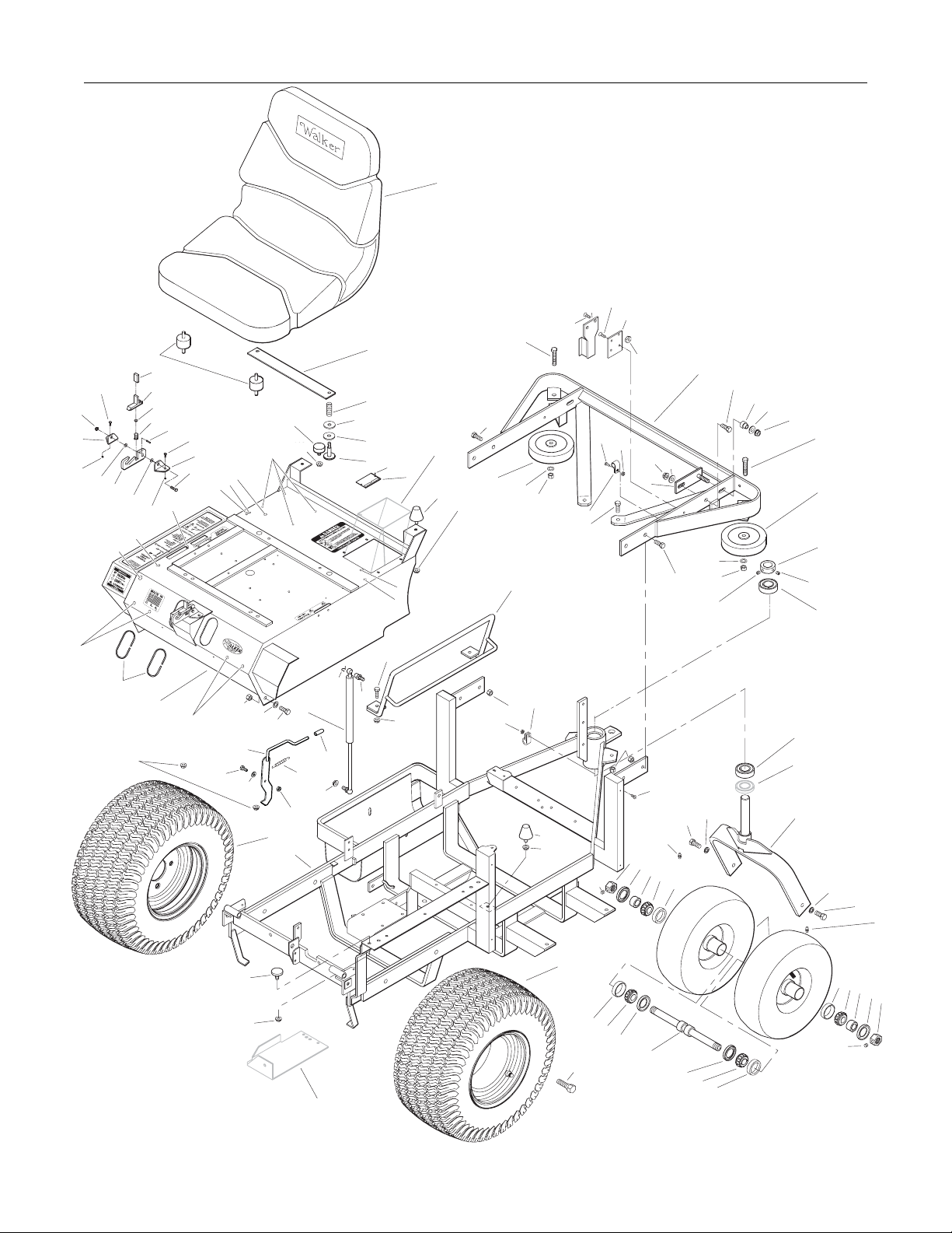
BODY / CHASSIS ASSEMBLY (GHS MODELS)
ITEM PART DESCRIPTION NO.
NO. NO. REQ’D
Seat Assembly
1 5103 Seat 1 2 7203 Seat Spring Plate 1 3 7223 Compression Spring (1/2 x 1) 2 4 7845 Rubber Bumper (1.375 OD x .63) 2 5 7846 Washer (3/8 ID x 1-1/4 OD x 1/8) 2 6 7204 Shoulder Bolt, Seat Mount 2 7 7440-5 Shock Mount (1-1/4 x 3/4) 2
Rear Bumper Assembly (GHS Models Only)
8 NS Recovery Tank Mount 1
(19449-72502 Kubota)
9 7047-5 Mount Plate 1 10 7516-7 7.0 / 9.5 Rear Bumper 1 11 7516-5 Catcher Pivot Bushing 2 12 5162 Roller Wheel (5" Rubber) 2 13 7517-2 Catcher Pivot Plate 2 14 5832 Cable Clamp (1/2) 2
Body Assembly
15 NS Body ID Plate 1 16 5845 Rubber Bumper (1.50 OD x 1.25) 4 17 7422 Panel Guard 1 18 5989-4 Dome Plug (3/8) 4 19 5989-3 Dome Plug (5/16) 2 20 7146 13mm Ball Stud 2 21 7844 Rubber Bumper (1.25 OD x .25) 1 22 7147 Spring Clip 2 23 7145 Gas Spring Assembly 1
(Includes Items # 20 & 22)
24 7222 Extension Spring (1/4 x 3) 1
25 7383-2 Body Latch Hook 1
26 7854 Plastic Tip, Red 1
27 5989-9 Dome Plug (1/4) 8
28 7100 Front Body 1
29 5180 Edge Molding, Lever Opening 2
30 5989-55 Dome Plug (1/2) 1
31 5989-5 Dome Plug (7/16) 1
Tilt-Up Latch Assembly
32 5847 Plastic Tip 1 33 5744-20 Spring Arm, Tilt-Up Latch 1 34 5744-10 Spring Pivot Bushing 1 35 5744-15 Compression Spring (3/8 x 5/8) 1 36 5744-13 Mount Angle, LH 1 37 5744-12 Hook, Tilt-Up Latch 1 38 5744-14 Mount Angle, RH 1
Chassis Assembly
39 5267-1 Retainer Collar (1") 1 40 5270-1 Pivot Bearing 2
41 7420 Tail Wheel Fork 1 42 5830-3 Grease Fitting (45 Degree) 2 43 8039 Nut, Tail Wheel Axle 2 44 8037-1 Seal, Outer (1-3/4 x 1-1/8) 2 45 8038-1 Spacer, Tail Wheel Axle 2
***
(Includes Item # F413)
*
ITEM PART DESCRIPTION NO.
NO. NO. REQ’D
46 8037 Bearing Cone (3/4 ID) 4 47 8037-2 Bearing Race 4 48 8035 Tail Wheel & Tire (13 x 5.00-6) 2
(With Bearing Race)
7035-1 Tail Wheel Tire (13 x 5.00-6)
8036 Tail Wheel & Hub (6 x 3.25) **
(Includes Items # 41 & 47)
7420-20 Dual Tail Wheel & Tire Assembly
(Includes Items # 43-46 & 48-50)
49 8768-2 Seal, Reverse Lip 2
50 8038 Tail Wheel Axle (3/4 x 10-3/8) 1
51 7070 Wheel & Tire (18 x 9.5-8) 2
7070-1 DriveTire (18 x 9.5-8)
5070-4 Wide Wheel (8 x 7) **
52 7300-5 Chassis Frame 1
Fasteners
F002 10-24 Keps Nut 2
F004 1/4-20 Keps Nut 6
F005 1/4-20 ESNA Nut 1
F009 5/16-18 Whiz Locknut 13
F012 3/8-16 Keps Nut 8
F013 3/8-16 Whiz Locknut 2
F014 3/8-16 ESNA Nut 4
F020 5/16-18 ESNA Nut 1
F026 10-24 x 1/2 PPHMS 2
F029 1/4-20 x 1/2 Hex Bolt 2
F031 1/4-20 x 5/8 Hex Bolt 1
F034 5/16-18 x 3/4 Hex Bolt 2
F038 3/8-16 x 1 Hex Bolt 6
F040 3/8-16 x 1-1/2 Hex Bolt 2
F042 3/8-16 x 2-1/4 Hex Bolt 2
F050 1/4 SAE Washer 1
F051 3/8 SAE Washer 2
F059 3/8 Wave Spring Washer 2
F093 5/16-18 x 1 Hex Bolt 1
F104 1/4-20 x 3/4 PFH Bolt 4
F151 3/8-16 x 7/8 Hex Bolt 2
F157 1/2-20 x 1-1/4 Wheel Lug Bolt 8
F205 5/16-18 x 1/4 Set Screw, Knurl Point 2
F206 #2 x 3/16 Drive Pin 2
F218 7/16 Split Lock Washer 2
F219 7/16-14 x 1-1/4 Hex Bolt 2
F227 3/8 x 1-1/4 x 1/8 Plastic Washer 2
F241 .375 x .875 x .10 Washer 4
F341 Coil Roll Pin (7/64 x 9/16) 1
F342 5/16 Conical Washer 2
F413 5/16-24 x 5/16 Set Screw 2
**
**
**
* Rear Bumper Assembly for SD Models is not shown here.
Refer to BODY ASSEMBLY (SD MODELS), Page 8.
** Service Part Only
*** Complete Tilt-Up Latch Assembly Kit available by ordering
kit # 5747.
Use only genuine Walker® replacement parts. Effective Date 03-01-06
4
Page 7
F020
38
F004
F029
F342
BODY / CHASSIS ASSEMBLY (GHS MODELS)
1
F104
8
9
F104
F004
F026
F002
F013
13
F014
17
14
F038
F241
F038
10
F059
F014
F413
F151
11
F241
F012
F042
12
39
F413
40
F009
F038
12
F042
F059
F227
2
3
F206
18
19
Refer to
GHS Group
15
16
5
6
7
32
33
34
35
F341
F029
36
F093
18
19
37
F342
18
F004
31
30
18
4
F009
27
27
F005
23
24
F009
22
26
Refer to
Electrical
Assembly
29
F009
28
F014
F031
25
F050
21
F009
F051
F040
51
52
27
F034
20
F009
F002
F012
14
F012
F026
F218
F219
16
F009
F205
51
47
46
F157
42
43
44
45
46
47
49
50
49
46
47
Effective Date 03-01-06 Use only genuine Walker
40
Refer to
Power Dump
Kit Assemblies
41
F218
48
47
F205
®
replacement parts.
F219
42
46
45
44
43
5
Page 8

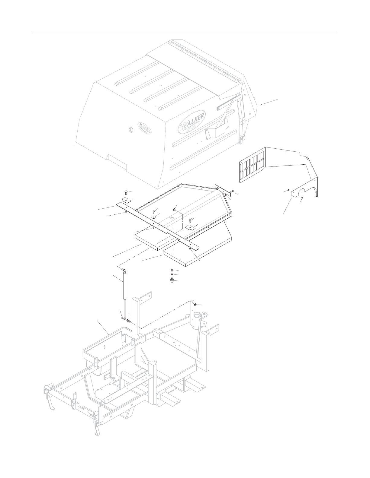
REAR BODY ASSEMBLY (GHS MODELS)
ITEM PART DESCRIPTION NO.
NO. NO. REQ’D
Rear Body Assembly (GHS Models)
1 8515-10 Catcher Reinforcing Plate 2 2 7515-2 Catcher Support Frame 1 3 7190-2 Insulation Foam Pad, RH 1 4 7190-1 Insulation Foam Pad, LH 1 5 7145 Gas Spring Assembly 1
(Includes Items # 6 & 7)
6 7147 Spring Clip 2
7 7146 13mm Ball Stud 2
8 5845 Rubber Bumper (1.50 x 1.25) 1
9 7105-5 Rear Body Panel 1
ITEM PART DESCRIPTION NO.
NO. NO. REQ’D
Fasteners
F002 10-24 Keps Nut 6
F004 1/4-20 Keps Nut 5
F009 5/16-18 Whiz Locknut 4
F025 10-24 x 3/8 PPHMS 6
F031 1/4-20 x 5/8 Hex Bolt 2
F032 1/4-20 x 3/4 Hex Bolt 1
F178 1/4 x 1 Fender Washer 1
F390 1/4-20 x 7/8 Carriage Bolt 2
NOTE: Rear Bumper Assembly for GHS Models is not shown
here. Refer to BODY / CHASSIS ASSEMBLY (GHS
MODELS), Page 4.
NOTE: Decals for this assembly are not shown here. Refer to
TRACTOR DECALS, Page 2 for Decal listing and place-
ment information.
Use only genuine Walker® replacement parts. Effective Date 03-01-06
6
Page 9
REAR BODY ASSEMBLY (GHS MODELS)
Refer to
GHS 7.0 Bushel Catcher &
Exhaust Deflector Assemblies
or GHS 9.5 Bushel Catcher Assembly
2
F004
Refer to
Body / Chassis Assembly
(GHS Models)
F390
1
F032
F004
3
5
6
4
7
F178
F009
F009
F009
8
F390
1
F004
F009
F031
F004
F002
F025
9
Effective Date 03-01-06 Use only genuine Walker
®
replacement parts.
7
Page 10

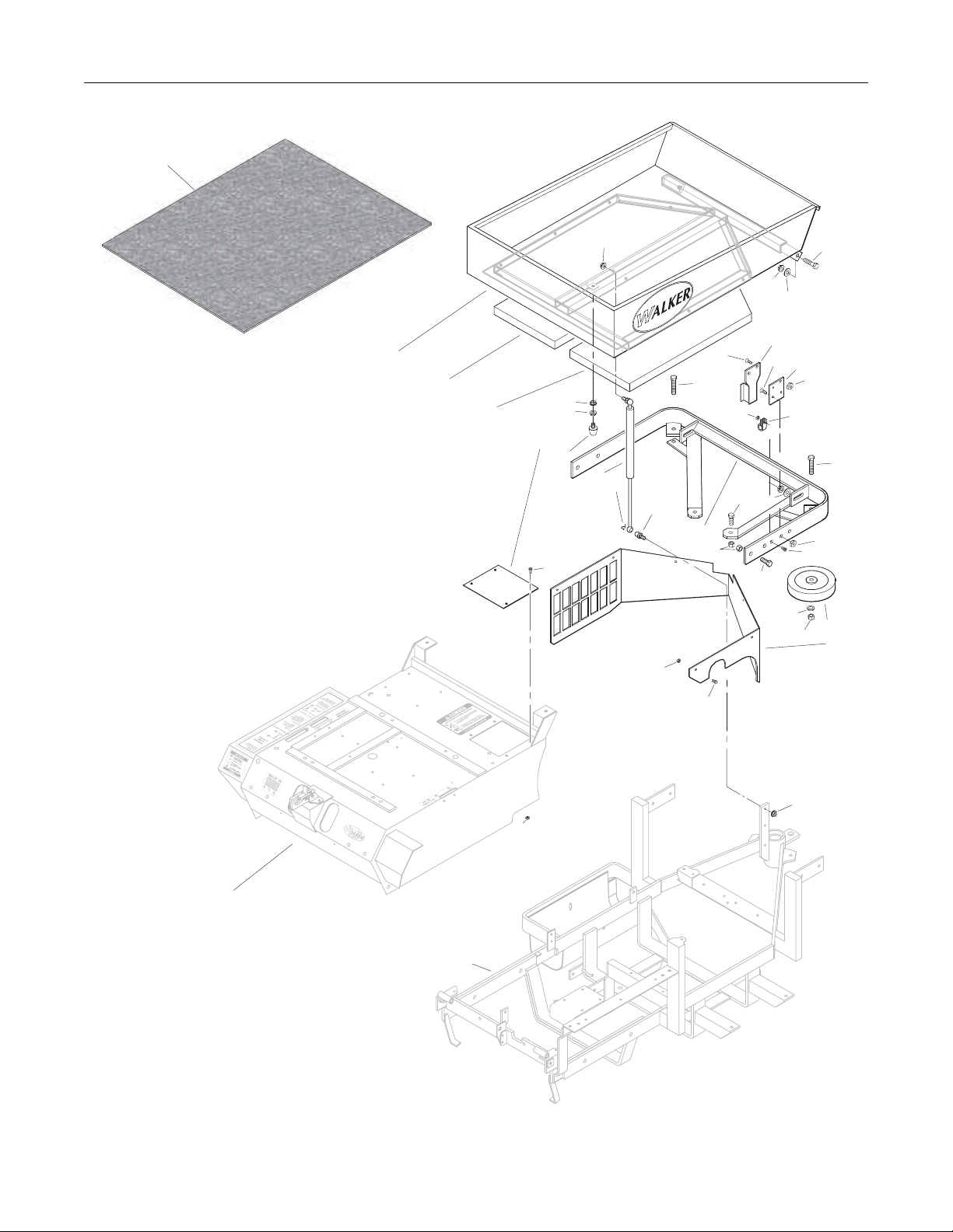
BODY ASSEMBLY (SD MODELS)
ITEM PART DESCRIPTION NO.
NO. NO. REQ’D
Utility Bed Assembly
1 8650-10 Bed Liner (21.5 x 27.5) 1 2 7650-3 Utility Bed (Includes Item # 1) 1 3 7190-2 Insulation Foam Pad, RH 1 4 7190-1 Insulation Foam Pad, LH 1
Rear Bumper Assembly (SD Models)
5 7153-3 Cover Plate 1 6 5845 Rubber Bumper (1.50 x 1.25) 1 7 7145 Gas Spring Assembly 1
(Includes Items # 8 & 9)
8 7147 Spring Clip 2
9 7146 13mm Ball Stud 2
10 7521-5 Rear Bumper 1 11 NS Recovery Tank Mount 1
(19449-72502 Kubota)
12 7047-5 Mount Plate 1 13 5832 Cable Clamp (1/2) 2 14 5162 Roller Wheel (5" Rubber) 2 15 7105-5 Rear Body Panel 1
ITEM PART DESCRIPTION NO.
NO. NO. REQ’D
Fasteners
F002 10-24 Keps Nut 11
F004 1/4-20 Keps Nut 4
F009 5/16-18 Whiz Locknut 4
F012 3/8-16 Keps Nut 6
F013 3/8-16 Whiz Locknut 4
F014 3/8-16 ESNA Nut 2
F025 10-24 x 3/8 PPHMS 6
F026 10-24 x 1/2 PPHMS 1
F038 3/8-16 x 1 Hex Bolt 6
F040 3/8-16 x 1-1/2 Hex Bolt 2
F042 3/8-16 x 2-1/4 Hex Bolt 2
F051 3/8 SAE Washer 4
F059 3/8 Wave Spring Washer 2
F104 1/4-20 x 3/4 PFH Bolt 4
F128 10-24 x 3/8 PTHMS 4
NOTE: Refer to BODY / CHASSIS ASSEMBLY (GHS MODELS),
Page 4 for all common parts used on both models.
Use only genuine Walker® replacement parts. Effective Date 03-01-06
8
Page 11
BODY ASSEMBLY (SD MODELS)
1
F009
F013
F002
F038
11
F104
F013
F051
F038
2
3
5
F009
F009
F128
6
7
8
9
F002
4
F104
F042
10
F012
F051
F059
F014
F040
12
F004
13
F042
F004
F026
14
15
F025
F002
Refer to
Body / Chassis Assembly
(GHS Models)
Refer to
Body / Chassis Assembly
(GHS Models)
Effective Date 03-01-06 Use only genuine Walker
F009
®
replacement parts.
9
Page 12

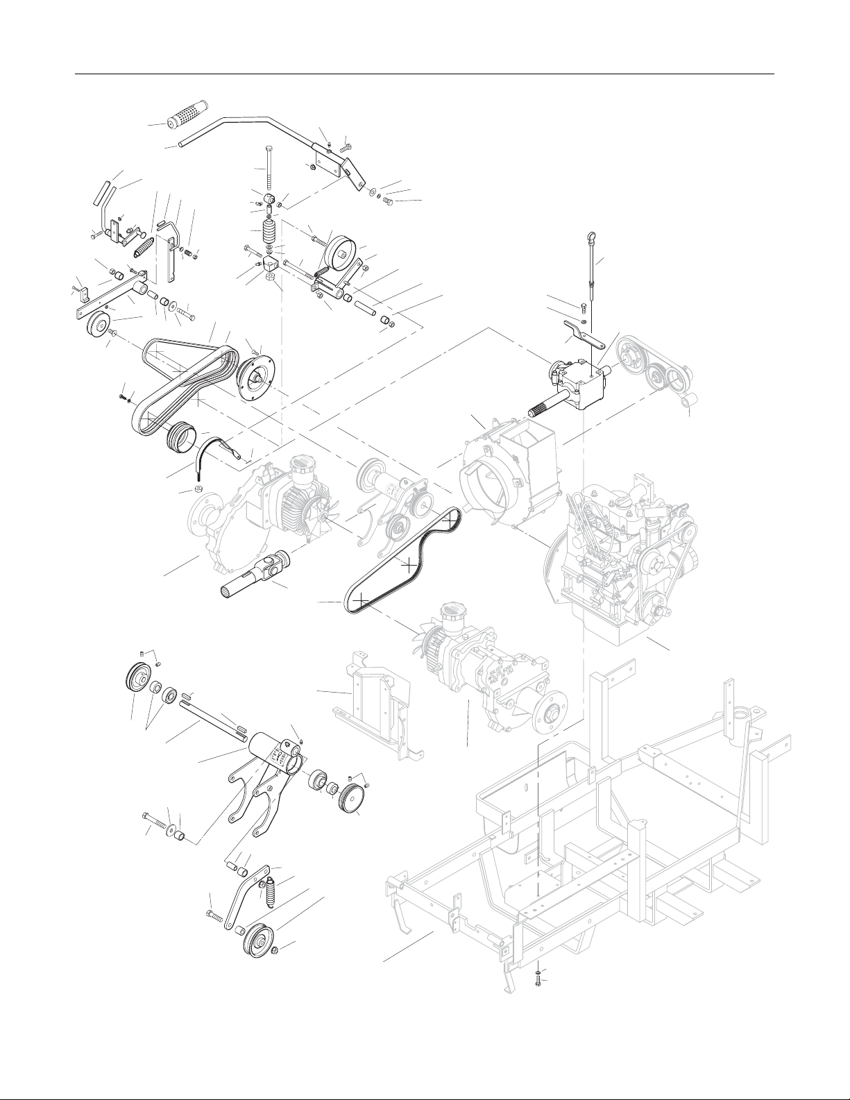
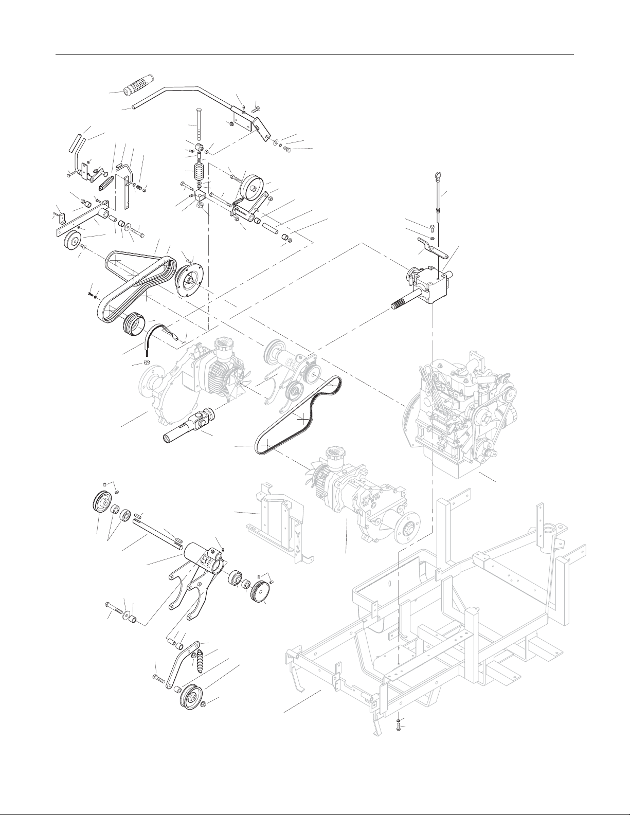
MAIN COMPONENT POWER TRANSMISSION (GHS MODELS)
ITEM PART DESCRIPTION NO.
NO. NO. REQ’D
Clutch Lever Assembly
1 5830 Grease Fitting 4 2 5229 Extension Spring (1/2 x 2-1/4) 1 3 7243 Clutch Idler Pulley 1 4 7368-2 PTO Belt Tightener (1.75 TAB) 1 5 7201-3 DU Bearing 6 6 7201-6 Inner Race (3-5/8) 1 7 7303-9 Clutch Actuator Block 1 8 7226 Compression Spring (3/4 x 2-1/2) 1 9 7380 Knuckle Joint 1
10 5830-3 Grease Fitting (45 Degree) 1 11 7303-7 Clutch Actuator Rod 1 12 7378 Pivot Bearing (7/16 x 9/16) 1 13 7358 Clutch Lever 1
(Includes Items # 1 & 14)
14 7860 Handle Grip 1
PTO Drive Shaft Assembly
15 7050-1 Dipstick, Gearbox 1 16 7377-1 Brake Band Guide 1 17 7050-11 PTO Gearbox / Flange Pulley 1 18 7248 Ground Drive Belt, Micro-V 1 19 7275-16 Universal Joint Tube Assembly / Spline 1 20 7303-2 Brake Band (13-5/8) 1 21 7236-1 PTO Drive Pulley (4-1/2 / 3V) 1
(Includes Items # F168 & F226)
22 7237-30 Engine Pulley (Flywheel Mount) 1
(Includes Item # F221)
23 7230 Engine PTO Belt 1 24 6231 Drive Belt (3VX355) 1
Jackshaft Assembly
25 7240-3 Jackshaft Drive Pulley (4.15/3V) 1
(Includes Items # F067 & F171)
26 5268 Bearing with Collar (3/4) 2 27 7273 Jackshaft (3/4 x 8-7/8) 1 28 7393-7 Hydro Jackshaft Mount 1
7394-1 Hydro Jackshaft Mount Assembly
(Includes Items # 1, 5, 26-28 & 30)
29 5841 Retainer Washer (3/8 x 1-1/4) 1 30 7201-4 Inner Race (1-1/2) 2 31 7349-50 Idler Arm 1 32 7349-2 Extension Spring (3/4 x 4) 1 33 6325-3 Spacer Bushing (9/16) 1 34 5245 Idler Pulley (3") 1 35 7241-2 Transmission Drive Pulley (3-1/4/MV) 1
(Includes Items # F067 & F171)
*
ITEM PART DESCRIPTION NO.
NO. NO. REQ’D
Ground Drive Release Assembly
36 7245-1 Idler Pulley (3/8 Groove) 1 37 7374 Ground Drive Release Arm 1 38 7390 Idler Arm Guide 1 39 7406-1 Handle Grip, Red 1 40 7376 Handle, Ground Drive Release 1
(Includes Item # 39)
41 5221 Extension Spring (3/4 x 4) 1
42 7854 Plastic Tip, Red 1
43 7375 Spring Arm, Ground Drive Idler Release 1
(Includes Item # 42)
44 7225 Compression Spring (7/16 x 1/2) 1
Fasteners
F002 10-24 Keps Nut 1
F004 1/4-20 Keps Nut 2
F005 1/4-20 ESNA Nut 2
F009 5/16-18 Whiz Locknut 3
F012 3/8-16 Keps Nut 4
F013 3/8-16 Whiz Locknut 2
F029 1/4-20 x 1/2 Hex Bolt 1
F041 3/8-16 x 1-3/4 Hex Bolt 1
F042 3/8-16 x 2-1/4 Hex Bolt 2
F047 3/8-16 x 4-1/2 Hex Bolt 1
F050 1/4 SAE Washer 1
F060 AN960516 Washer 2
F061 1/4 Internal Star Lock Washer 1
F067 3/16 x 3/16 x 1 Key 2
F069 3/32 x 1/2 Cotter Pin 1
F108 3/8-16 x 2 Hex Bolt 1
F116 1/4-20 x 1-1/4 Hex Bolt 1
F167 5/16-18 Hex Nut 1
F168 5/16 Split Lock Washer 10
F171 5/16-18 x 3/8 Set Screw 4
F178 1/4 x 1 Fender Washer 1
F187 1/4-20 x 1-1/2 Hex Bolt 2
F221 M8 x 1.25 x 16 PFH Bolt 5
F226 5/16-18 x 7/8 Hex Bolt 6
F245 3/8-24 x 7/8 SFH Cap Screw 1
F252 10-24 x 3/4 PFHMS 1
F255 5/16-18 x 1-1/2 Hex Bolt 2
F275 5/16-18 x 2 Hex Bolt 1
F288 5/16-18 ESNA Jam Nut 1
* Service Part Only
Use only genuine Walker® replacement parts. Effective Date 03-01-06
10
Page 13
F252
38
F187
F012
5
F245
F116
F002
F226
MAIN COMPONENT POWER TRANSMISSION (GHS MODELS)
12
F060
F060
F288
F167
F009
F041
1
F047
2
F009
F255
F012
3
F012
F178
F061
F029
4
5
6
5
Refer to
GHS Group
F226
F168
16
39
F004
14
1
37
F168
13
40
41
42
43
44
F005
F050
F042
36
30
5
29
11
9
10
9
8
F275
1
7
24
23
F221
22
21
F069
15
17
Refer to
GHS Group
20
F005
Refer to
Hydrostatic Ground
Drive Assemblies
F171
25
26
27
29
5
F042
28
F067
F108
F067
Refer to
Hydrostatic Ground
Drive Assemblies
1
30
5
31
F013
19
18
Refer to
Engine Group
Refer to
F171
26
26
35
32
33
34
Hydrostatic Ground
Drive Assemblies
F013
Refer to
Body / Chassis Assembly
(GHS Models)
F168
F226
Effective Date 03-01-06 Use only genuine Walker
®
replacement parts.
11
Page 14

MAIN COMPONENT POWER TRANSMISSION (SD MODELS)
ITEM PART DESCRIPTION NO.
NO. NO. REQ’D
Clutch Lever Assembly
1 5830 Grease Fitting 4 2 5229 Extension Spring (1/2 x 2-1/4) 1 3 7243 Clutch Idler Pulley 1 4 7368-2 PTO Belt Tightener (1.75 TAB) 1 5 7201-3 DU Bearing 6 6 7201-6 Inner Race (3-5/8) 1 7 7303-9 Clutch Actuator Block 1 8 7226 Compression Spring (3/4 x 2-1/2) 1
9 7380 Knuckle Joint 1 10 5830-3 Grease Fitting (45 Degree) 1 11 7303-7 Clutch Actuator Rod 1 12 7378 Pivot Bearing (7/16 x 9/16) 1 13 7358 Clutch Lever 1
(Includes Items # 1 & 14)
14 7860 Handle Grip 1
PTO Drive Shaft Assembly
15 7050-1 Dipstick, Gearbox 1 16 7377-1 Brake Band Guide 1 17 7050-11 PTO Gearbox / Flange Pulley 1 18 7248 Ground Drive Belt, Micro-V 1 19 7275-16 Universal Joint Tube Assembly / Spline 1 20 7303-2 Brake Band (13-5/8) 1 21 7236-1 PTO Drive Pulley (4-1/2 / 3V) 1
(Includes Items # F168 & F226)
22 7237-30 Engine Pulley (Flywheel Mount) 1
(Includes Item # F221)
23 7230 Engine PTO Belt 1
24 6231 Drive Belt (3VX355) 1
Jackshaft Assembly
25 7240-3 Jackshaft Drive Pulley (4.15/3V) 1
(Includes Items # F067 & F171)
26 5268 Bearing with Collar (3/4) 2
27 7273 Jackshaft (3/4 x 8-7/8) 1
28 7393-7 Hydro Jackshaft Mount 1
7394-1 Hydro Jackshaft Mount Assembly
(Includes Items # 1, 5, 26-28 & 30)
29 5841 Retainer Washer (3/8 x 1-1/4) 1
30 7201-4 Inner Race (1-1/2) 2
31 7349-50 Idler Arm 1
32 7349-2 Extension Spring (3/4 x 4) 1
33 6325-3 Spacer Bushing (9/16) 1
34 5245 Idler Pulley (3") 1
35 7241-2 Transmission Drive Pulley (3-1/4/MV) 1
(Includes Items # F067 & F171)
*
ITEM PART DESCRIPTION NO.
NO. NO. REQ’D
Ground Drive Release Assembly
36 7245-1 Idler Pulley (3/8 Groove) 1 37 7374 Ground Drive Release Arm 1 38 7390 Idler Arm Guide 1 39 7406-1 Handle Grip, Red 1 40 7376 Handle, Ground Drive Release 1
(Includes Item # 39)
41 5221 Extension Spring (3/4 x 4) 1
42 7854 Plastic Tip, Red 1
43 7375 Spring Arm, Ground Drive Idler Release 1
(Includes Item # 42)
44 7225 Compression Spring (7/16 x 1/2) 1
Fasteners
F002 10-24 Keps Nut 1
F004 1/4-20 Keps Nut 2
F005 1/4-20 ESNA Nut 2
F009 5/16-18 Whiz Locknut 3
F012 3/8-16 Keps Nut 4
F013 3/8-16 Whiz Locknut 2
F029 1/4-20 x 1/2 Hex Bolt 1
F041 3/8-16 x 1-3/4 Hex Bolt 1
F042 3/8-16 x 2-1/4 Hex Bolt 2
F047 3/8-16 x 4-1/2 Hex Bolt 1
F050 1/4 SAE Washer 1
F060 AN960516 Washer 2
F061 1/4 Internal Star Lock Washer 1
F067 3/16 x 3/16 x 1 Key 2
F069 3/32 x 1/2 Cotter Pin 1
F108 3/8-16 x 2 Hex Bolt 1
F116 1/4-20 x 1-1/4 Hex Bolt 1
F167 5/16-18 Hex Nut 1
F168 5/16 Split Lock Washer 10
F171 5/16-18 x 3/8 Set Screw 4
F178 1/4 x 1 Fender Washer 1
F187 1/4-20 x 1-1/2 Hex Bolt 2
F221 M8 x 1.25 x 16 PFH Bolt 5
F226 5/16-18 x 7/8 Hex Bolt 6
F245 3/8-24 x 7/8 SFH Cap Screw 1
F252 10-24 x 3/4 PFHMS 1
F255 5/16-18 x 1-1/2 Hex Bolt 2
F275 5/16-18 x 2 Hex Bolt 1
F288 5/16-18 ESNA Jam Nut 1
* Service Part Only
Use only genuine Walker® replacement parts. Effective Date 03-01-06
12
Page 15
F252
38
F187
F012
5
F245
F116
F002
F226
39
F004
MAIN COMPONENT POWER TRANSMISSION (SD MODELS)
12
F060
F060
F288
F167
F009
F041
1
F047
2
F009
F255
F012
3
F012
F178
F061
F029
4
5
6
5
F226
F168
16
14
1
37
F168
13
40
41
42
43
44
F005
F050
F042
36
30
5
29
11
9
10
9
8
F275
1
7
24
23
F221
22
21
F069
15
17
20
F005
Refer to
Hydrostatic Ground
Drive Assemblies
F171
25
26
27
29
5
F042
F067
28
F067
F108
Refer to
Hydrostatic Ground
Drive Assemblies
1
30
5
31
F013
19
18
Refer to
Engine Group
Refer to
F171
26
26
35
32
33
34
Hydrostatic Ground
Drive Assemblies
F013
Refer to
Body / Chassis Assembly
(GHS Models)
F168
F226
Effective Date 03-01-06 Use only genuine Walker
®
replacement parts.
13
Page 16

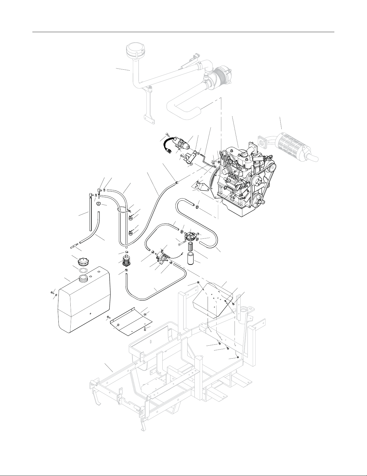
ENGINE GROUP
ITEM PART DESCRIPTION NO.
NO. NO. REQ’D
Engine Assembly
1 7929 Actuating Solenoid 1 2 7343 Solenoid Mount 1 3 7305 Solenoid Linkage Rod 1 4 NS Kubota Diesel Engine 1
(D 722 Kubota)
5 7341 Throttle Cable Mount Bracket 1
Fuel Tank Assembly
6 5083-2 Tank Tube Elbow 1 7 5879-3 Hose Clamp (1/2) 2 8 7015-14 Hose (1/4 x 16-1/2) 1
9 5975-3 Cable Tie (50# x 7") 1 10 7833 Cable Clamp (7/8 x 1/4) 2 11 7015-12 Hose (3/16 x 32) 1 12 5879-2 Hose Clamp, Silver (7/16) 2 13 7840-2 Hose Clamp (1/4 to 5/8) 6 14 7015-16 Hose (5/16 x 14-1/2) 1 15 NS Fuel Filter (19204-43010 Kubota) 1 16 7015-17 Hose (5/16 x 25-1/2) 1 17 7021 Fuel Filter (15231-43560 Kubota) 1 18 7389 Splash Guard 1 19 7048 Trash Guard 1 20 7015-15 Hose (5/16 x 17-1/2) 1 21 NS Fuel Pump (12691-52031 Kubota) 1 22 7020 Fuel Filter (In-Line) 1 23 8046-8 Fuel Tank, 5 Gallon, Diesel 1
(Includes Items # 25 & 28)
24 5082-2 Fuel Cap Seal
25 7082 Fuel Tank Cap, Diesel *
(Includes Item # 24)
*
ITEM PART DESCRIPTION NO.
NO. NO. REQ’D
26 5020-2 Fuel Filter, In Tank 1 27 5086 Fuel Line (In Tank P/U) 1 28 5083-1 Bushing, Rubber 29 7046-1 Fuel Return Tube 1
Fasteners
F002 10-24 Keps Nut 4
F003 1/4-28 Hex Nut 1
F004 1/4-20 Keps Nut 6
F009 5/16-18 Whiz Locknut 2
F027 10-24 x 5/8 PPHMS 3
F029 1/4-20 x 1/2 Hex Bolt 5
F031 1/4-20 x 5/8 Hex Bolt 5
F050 1/4 SAE Washer 1
F061 1/4 Internal Star Lock Washer 1
F069 3/32 x 1/2 Cotter Pin 1
F079 A/A66D Aluminum Pop Rivet 2
F091 5/16-18 x 5/8 Hex Bolt 1
F182 5/8 x 1/4 x 1/8 Washer 2
F233 M8 x 1.25 x 16 Hex Bolt 2
F235 5/16-18 x 2-1/2 Hex Bolt 1
*
* Service Part Only
NOTE: Refer to ELECTRICAL CONNECTORS, Page 42 for iden-
tification of all Electrical Wiring Service Parts.
NOTE: Decals for this assembly are not shown here. Refer to
TRACTOR DECALS, Page 2 for Decal listing and place-
ment information.
Use only genuine Walker® replacement parts. Effective Date 03-01-06
14
Page 17
Refer to Air Intake
& Exhaust Group
ENGINE GROUP
2
1
Refer to Air Intake
4
3
& Exhaust Group
F061
F029
F031
F182
12
F091
6
7
12
28
29
27
26
25
24
23
7
22
13
11
8
9
F079
10
F079
10
13
F002
19
21
20
F004
13
14
F235
F002
F004
13
F002
F003
F009
F069
F050
F233
5
13
15
F009
13
16
17
15
18
F027
F029
F029
F004
Refer to
Body / Chassis Assembly
(GHS Models)
F031
F029
F031
F002
Effective Date 03-01-06 Use only genuine Walker
®
replacement parts.
15
Page 18

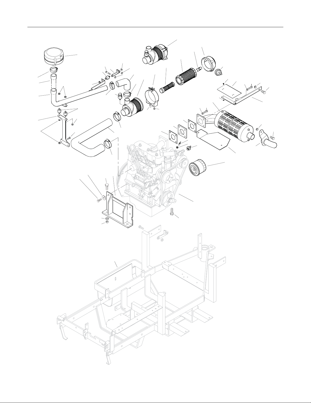
AIR INTAKE AND EXHAUST GROUP
ITEM PART DESCRIPTION NO.
NO. NO. REQ’D
Precleaner Assembly
1 7026-2 Remote Precleaner (Includes Item # 5) 1
2 7440 Shock Mount (1.0 OD x .75) 3
3 7028-20 Rear Precleaner Mount 1
4 7027 Elbow, Precleaner 1
5 7840 Hose Clamp (1-5/16 to 2-1/4) 3
6 5088-10 Air Cleaner Assembly
(Includes Item # 15)
7 5088-1 Air Cleaner Band 1
8 5090-3 Safety Filter Insert 1
9 5090-1 Air Cleaner Cartridge 1
10 5088-5 Air Cleaner Draw Latch 2 11 5088-11 Air Cleaner Cap 1 12 5090-2 Vacuator Valve 1 13 6029 Hose Clamp (2-1/2) 1 14 7016 Air Intake Hose 1 15 5091-10 Air Flow Indicator & Nipple 1 16 7031 Tube Support Arm 1 17 7028-3 Precleaner Tube, SD 1 18 7028-2 Precleaner Tube, GHS 1
Exhaust Assembly
*
ITEM PART DESCRIPTION NO.
NO. NO. REQ’D
Fasteners
F002 10-24 Keps Nut 2
F009 5/16-18 Whiz Locknut 10
F012 3/8-16 Keps Nut 1
F025 10-24 x 3/8 PPHMS 2
F038 3/8-16 x 1 Hex Bolt 2
F091 5/16-18 x 5/8 Hex Bolt 2
F217 7/16-14 Hex Nut 4
F218 7/16 Split Lock Washer 4
F219 7/16-14 x 1-1/4 Hex Bolt 4
(GHS Models use only 3)
F226 5/16-18 x 7/8 Hex Bolt 1
F239 7/16-14 x 1-1/2 Hex Bolt 1
F249 M10 Split Lock Washer 8
F253 M8 x 1.25 x 35 GR 8 Bolt 3
F255 5/16-18 x 1-1/2 Hex Bolt 2
F311 M10 x 1.25 x 20 Hex Bolt 8
F327 M8 x 1.25 x 40 GR8 Hex Bolt 1
*
**
***
* Two (2) F009 and two (2) F035 fasteners are reused from
Clutch Lever Assembly. Refer to MAIN COMPONENT POWER
TRANSMISSION (GHS OR SD MODELS), Pages 10 or 12.
19 7437-1 Exhaust Manifold Shield 1 20 NS Spring Washer (04512-50080 Kubota) 4 21 7437-6 Engine Brace 1
(Includes Items # 19, F002 & F025)
22 NS Muffler (15262-12110 Kubota) 1
23 NS Muffler Gasket (15371-12370 Kubota) 2
24 7034 Spacer, Muffler 1
25 7354 Motor Mount 2
26 7306-15 Water Temperature Sender 1
27 7306-12 Temperature Sender Adapter 1
28 7306-13 Oil Pressure Switch 1
29 7023 Oil Filter (15841-32429 Kubota) 1
30 7047-2 Manifold Heat Shield 1
31 7013-2 Tail Pipe 1
** One (1) F012 and one (1) F038 fastener are reused from
Rear Bumper Assembly. Refer to BODY / CHASSIS ASSEMBLY (GHS MODELS), Page 4.
*** GHS Models Only
Use only genuine Walker® replacement parts. Effective Date 03-01-06
16
Page 19
5
18
17
16
F009
F009
1
2
F009
F255
AIR INTAKE AND EXHAUST GROUP
6
9
8
23
24
F009
F038
2
F009
3
15
5
5
F009
4
F009
5
13
14
6
F091
7
F009
23
11
10
12
F025
19
20
F002
22
F253
20
26
27
28
30
29
F327
31
F009
21
F012
F226
F038
F311
F249
25
F219
F218
F217
Refer to
Body / Chassis Assembly
(GHS Models)
Refer to
Engine Group
F239
(GHS Models Only)
Effective Date 03-01-06 Use only genuine Walker
®
replacement parts.
17
Page 20

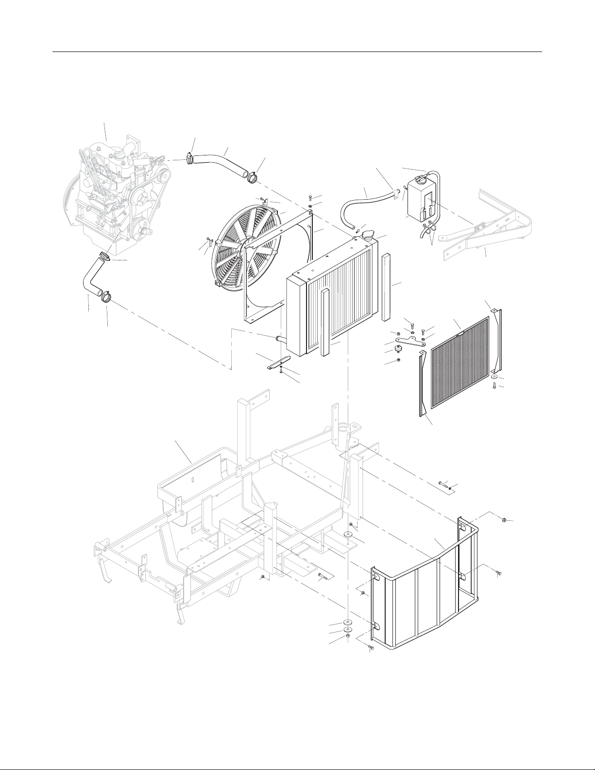
5$',$725*5283
,7(0 3$57 '(6&5,37,21 12
12 12 5(4·'
5DGLDWRU$VVHPEO\
+RVH&ODPSWR
8SSHU5DGLDWRU+RVH
+RVH&ODPSWR
)DQ0RXQW7DE/+
5DGLDWRU&RROLQJ)DQ
)DQ%ODGH5HSODFHPHQW
,QFOXGHV,WHPV))
)))
5DGLDWRU)DQ6KURXG
16 5HFRYHU\7DQN+RVH&ODPS
.XERWD
5HFRYHU\7DQN+RVH
16 &RRODQW5HFRYHU\7DQNDQG+RVH
.XERWD
&DEOH7LH[
5DGLDWRU
5DGLDWRU&KDQQHO6HDO[[
5DGLDWRU%UDFH
6KRFN0RXQW2'[
5DGLDWRU6FUHHQ
6FUHHQ&KDQQHO
5DGLDWRU*XDUG
5HWDLQHU:DVKHU[
5XEEHU:DVKHU[[
'HEULV6KLHOG6KURXG
)DQ0RXQW7DE5+
/RZHU5DGLDWRU+RVH
,7(0 3$57 '(6&5,37,21 12
12 12 5(4·'
)DVWHQHUV
) .HSV1XW
) (61$1XW
) [+H[%ROW
) [+H[%ROW
) ,QWHUQDO6WDU/RFN:DVKHU
) [)HQGHU:DVKHU
) %HOOHYLOOH:DVKHU66
) [+H[%ROW
) [37+06
) [:KL]/RFN%ROW
) 7KUXVW:DVKHU
) 6SULQJ5LQJ
) )HQGHU:DVKHU
6HUYLFH3DUW2QO\
127( 'HFDOV IRU WKLV DVVHPEO\ DUH QRW VKRZQ KHUH 5HIHU WR
75$&725'(&$/6 3DJH IRU 'HFDOOLVWLQJDQGSODFH
PHQWLQIRUPDWLRQ
8VHRQO\JHQXLQH:DONHUUHSODFHPHQWSDUWV (IIHFWLYH'DWH
18
Page 21
Refer to
Engine Group
5$',$725*5283
1
2
3
F129
4
5
F031
F061
6
Refer to
Body / Chassis Assembly
(GHS Models)
8
7
11
9
7
9
3
22
3
Refer to
Body / Chassis Assembly
(GHS Models)
F129
21
F029
F061
F004
F004
13
14
F004
19
12
20
F061
F029
10
Refer to
Body / Chassis Assembly
15
F090
(GHS Models)
16
F073
F029
F061
F004
12
F029
F061
16
17
F004
F090
F014
F004
19
18
F031
F031
(IIHFWLYH'DWH 8VHRQO\JHQXLQH:DONHUUHSODFHPHQWSDUWV
19
Page 22

HYDROSTATIC GROUND DRIVE ASSEMBLIES
ITEM PART DESCRIPTION NO.
NO. NO. REQ’D
Transmission Lockout Assembly
1 5028-3 Transmission Lockout Assembly
(Includes Items # 2-5, F023, F027 & F081)
2 5847 Plastic Tip 2 3 5057 Lockout Cam 2
(Includes Item # F081)
4 5028-5 Lockout Lever 2 5 5027-5 Lockout Mount 2
Ground Drive Assemblies
6 6209-1 Bridge Assembly 1 7 5832 Cable Clamp (1/2) 1 8 7394-7 Throttle Cable Mount Bracket 1
9 6243-2 Hydro Fan, CCW 1 10 5025 Hydrostatic Drive, CCW (700-042) 1 11 6206-1 Air Vent Valve 12 6200-9 Gear Axle Drive Assembly 2
(Includes Items # 11 & 13)
13 6207-12 Pipe Plug (1/4 NPTF) 4
14 5126 Cable Retainer 1
(Uses existing bolt on
Gear Axle Drive Assembly)
15 6233-1 Pinion Gear 2
16 6234 Spacer, Pinion Gear 2
17 6201 O-Ring Seal 2
18 7244 Hydro Pulley (3-7/8/MV) 2
(Includes Items # F064 & F359)
19 6243-1 Hydro Fan, CW 1
20 5026 Hydrostatic Drive, CW (700-041) 1
Deck Support Arm Assemblies
21 6430-10 Outboard Mount, LH 1 22 6430-2 Deck Support Arm, LH 1
(Includes Item # 26)
23 5775-2 Hitch Pin (# 6) 2
24 6430-1 Deck Support Arm, RH 1
(Includes Item # 26)
25 6430-9 Outboard Mount, RH 1
26 5830 Grease Fitting 2
27 6840-1 Support Arm Bushing (2-1/16) 2
*
*
ITEM PART DESCRIPTION NO.
NO. NO. REQ’D
Transmission Repair Parts
28 5025-5 Input Shaft
29 5025-8 Bearing, Input Shaft *
30 5025-7 Snap Ring *
31 5025-2 Seal, Input Shaft *
32 5022 Reservoir to Casting Gasket *
33 5024 Reservoir Cap and Gasket *
34 5023 Transmission Reservoir Kit *
35 5023-1 Rubber Bladder *
36 5025-6 O-Ring & Plug Assembly *
37 5025-3 Seal, Control Shaft *
Fasteners
F012 3/8-16 Keps Nut 1
F023 10-24 ESNA Nut 2
F026 10-24 x 1/2 PPHMS 1
F027 10-24 x 5/8 PPHMS 2
F036 1/4-20 x 1/2 SBH Screw 2
F038 3/8-16 x 1 Hex Bolt 4
F040 3/8-16 x 1-1/2 Hex Bolt 4
F043 3/8-16 x 3 Hex Bolt 7
F051 3/8 SAE Washer 2
F053 7/16 Internal Star Lock Washer 4
F063 3/8 Internal Star Lock Washer 14
F064 1/8 x 1/2 Woodruff Key (#3) 6
F081 A/A45D Aluminum Pop Rivet 2
F160 External Snap Ring (.669 Shaft) 2
F178 1/4 x 1 Fender Washer 2
F194 7/16 x 1-1/4 x 1/8 Washer 2
F200 7/16-20 x 3 Grade 8 Bolt 2
F244 7/16-20 x 3/4 Hex Bolt 2
F262 3/8-16 x 4 Hex Bolt All Thread 1
F359 5/16-18 x 5/16 Set Screw 4
(Unbrako Knurl Point)
F416 3/8-16 x 4 Socket Head Cap Screw 1
*
* Service Part Only
Use only genuine Walker® replacement parts. Effective Date 03-01-06
20
Page 23

HYDROSTATIC GROUND DRIVE ASSEMBLIES
F038
F063
25
28
F200
33
32
31
30
29
12
13
F160
13
F053
15
F244
F053
34
35
36
30
F026
37
11
F012
F064
16
17
18
26
7
20
F036
F178
9
27
F012
8
F051
F051
F359
F359
F064
F359
F064
F359
18
6
F043
Refer to
Main Component Power
Transmission (GHS Models)
5
F262
F416
19
F178
F036
10
F063
F023
11
1
F081
F027
2
3
4
12
14
13
F053
F200
16
F064
15
F244
F160
F063
23
24
23
F194
F194
22
21
27
26
17
F053
Effective Date 03-01-06 Use only genuine Walker
F043
13
®
replacement parts.
F040
F063
21
Page 24

STEERING CONTROL ASSEMBLIES
ITEM PART DESCRIPTION NO.
NO. NO. REQ’D
Transmission Spring Assemblies
1 6199-10 Transmission Spring Assembly (RH)
(Includes Items # 2-8, F003,
F287, F320 & F352)
2 5552 Ball Joint (1/4-28) 2 3 5192-1 Spring Plunger (Male) 2 4 5194 Plunger Sleeve 2 5 5193 Washer (3/4 x 1 x .085) 2 6 6191 Spring Slide (4-3/4) 1 7 5195-2 Compression Spring (1 x 6-3/8) 2 8 6196 Spring Slide Cap 1
9 5197 J-Bolt 1 10 5191 Spring Slide (3-5/8) 1 11 5199-10 Transmission Spring Assembly (LH)
(Includes Items # 2-5, 7, 9, 10,
F003, F146, F287 & F352)
Steering Lever & FSC Assemblies
12 5214-2 Ball Joint (5/16-24) Nylon Lined 2 13 5173 FSC Actuator Rod 1 14 5172 Bearing, Nylon (.255 ID x .379 OD x .250) 1 15 5142-2 FSC Actuator Cam 1 16 5830 Grease Fitting 6 17 6212 Transmission Control Arm, RH 1 18 5141 FSC Friction Washer (1-1/2 x 3/8 x 1/16) 2 19 5140-15 FSC Friction Body 1
(Includes Item # 16)
20 5142-7 FSC Key W/Stop 1
5140-13 FSC Control Assembly
(Includes Items # 16, 18-20, F192 & F193)
21 5850-2 Handle Grip, Foam (5-1/2) 2
22 5212-2 Transmission Control Arm, LH 1
23 5213-2 Control Rod, LH (6") 1
24 5223 Extension Spring (1/4 x 5-1/2) 2
25 5450 D-Clip 2
26 5463 Steering Lever Actuator 2
27 5214-1 Bearing (.320 x .438 x .250) 2
28 5391-3 Steering Lever Support 1
29 5217 Pivot Pin, Steering Lever 1
30 5451-3 Steering Lever Assembly, LH / Adjustable 1
(Includes Items # 16, 21, 36,
F188, F198 & F345)
5451-5 Steering Lever Arm, LH / Adjustable
31 5219 Extension Spring (3/4 x 6-3/4) 1
32 5280 Clevis (1/4) 1
33 5281-5 Clevis Pin (1/4 x 0.80) 1
34 5470-1 Speed Control Stop 1
*
*
*
*
ITEM PART DESCRIPTION NO.
NO. NO. REQ’D
35 5450-3 Steering Lever Assembly, RH / Adjustable 1
(Includes Items # 16, 21, 36,
F188, F198 & F345)
5450-5 Steering Lever Arm, RH / Adjustable
36 5453-10 Steering Lever Handle / Adjustable 2
(Includes Items # 21 & F345)
37 5862 FSC Knob 1
38 7170 FSC Lever Assembly 1
(Includes Item # 16)
39 5975-3 Cable Tie (50# x 7") 1
40 5213-1 Control Rod, RH (15") 1
Fasteners
F003 1/4-28 Hex Nut 3
F004 1/4-20 Keps Nut 8
F007 5/16-18 Jam Nut 1
F008 5/16-24 Keps Nut 2
F009 5/16-18 Whiz Locknut 1
F010 5/16-24 ESNA Nut 2
F012 3/8-16 Keps Nut 2
F024 5/16-24 Jam Nut 2
F029 1/4-20 x 1/2 Hex Bolt 2
F032 1/4-20 x 3/4 Hex Bolt 4
F034 5/16-18 x 3/4 Hex Bolt 1
F050 1/4 SAE Washer 3
F051 3/8 SAE Washer 2
F064 1/8 x 1/2 Woodruff Key (#3) 2
F068 1/8 x 1 Cotter Pin 1
F069 3/32 x 1/2 Cotter Pin 1
F093 5/16-18 x 1 Hex Bolt 1
F146 1/4-20 Jam Nut 1
F182 1/4 x 5/8 x 1/8 Washer 2
F183 .312 x .700 x .074 Washer 2
F186 5/64 x 1/2 Cotter Pin 1
F188 1/4-20 Self-Locking Nut 4
F192 3/8-24 Self-Locking Nut 1
F193 3/8 Belleville Spring Washer 3
F198 .250 x .625 x .040 Washer, SS 2
F287 1/4-28 Keps Nut 2
F320 1/8 x 3/4 Split Spring Pin 1
F345 1/4-20 x .770 Knurled Bolt 4
F352 5/32 x 1 Heavy Duty Roll Pin 2
F401 .504 x .751 x .030 Washer 1
*
* Service Part Only
Use only genuine Walker® replacement parts. Effective Date 03-01-06
22
Page 25

Refer to
Electrical Assembly
STEERING CONTROL ASSEMBLIES
1
37
38
F032
16
Refer to
Hydrostatic Ground
Drive Assemblies
F004
F401
F345
F004
27
16
35
F182
F051
F012
F003
2
F352
3
4
5
6
F287
9
5
7
F146
19
18
20
F193
F192
21
F345
23
24
25
16
F320
7
3
F064
8
2
F287
11
12
F008
10
4
F352
F003
22
F024
F051
F012
21
36
F004
F004
40
32
29
F029
F183
F010
34
39
F198
F188
24
25
16
33
26
F007
F093
F186
F003
31
28
F032
F004
F050
F034
13
F068
F024
14
F032
F050
30
F008
15
F009
F188
16
F069
36
F198
16
12
F064
17
18
Refer to
Body / Chassis Assembly
(GHS Models)
F010
26
F182
F183
27
F004
Effective Date 03-01-06 Use only genuine Walker
®
replacement parts.
23
Page 26

THROTTLE CONTROL ASSEMBLIES
ITEM PART DESCRIPTION NO.
NO. NO. REQ’D
Throttle & Choke Control Assemblies
1 5832 Cable Clamp (1/2) 2 2 7220 Throttle Cable 1 3 NS 10-32 Jam Nut 2 4 5150 Ball Joint (10-32) 2 5 5108-7 Control Lock Tab 1 6 5108-10 Friction Washer (.125) 1 7 5108-1 Control Lever, Throttle 1 8 5108-5 Throttle Control Knob, Red 1
9 5108-11 Friction Washer (.062) 1 10 5108-8 Control Bracket (Diesel) 1 11 7108 Control Assembly
(Includes Items # 5-7, 9, 10 & F201)
12 7112 Throttle Control and Cable Assembly
(Complete Control and Cable Assembly)
(Includes Items # 2, 4, 8, 11 & F232)
*
*
ITEM PART DESCRIPTION NO.
NO. NO. REQ’D
Fasteners
F002 10-24 Keps Nut 4
F005 1/4-20 ESNA Nut 1
F025 10-24 x 3/8 PPHMS 4
F201 1/4 Belleville Spring Washer 2
F232 10-32 Keps Nut 2
* Service Part Only
NOTE: Decals for this assembly are not shown here. Refer to
TRACTOR DECALS, Page 2 for Decal listing and placement
information.
Use only genuine Walker® replacement parts. Effective Date 03-01-06
24
Page 27

THROTTLE CONTROL ASSEMBLIES
Refer to
Body / Chassis Assembly
(GHS Models)
Refer to
Engine Group
F002
F232
F025
10
9
8
7
6
5
F005
F201
1
F002
1
2
F002
F232
4
3
F002
12
F025
3
4
11
Effective Date 03-01-06 Use only genuine Walker
®
replacement parts.
25
Page 28

PARKING BRAKE ASSEMBLY
ITEM PART DESCRIPTION NO.
NO. NO. REQ’D
Parking Brake Assembly
1 7406-1 Handle Grip, Red 1
2 7406-8 Parking Brake Lever (4-1/4) 1
3 7406-2 Lever Mount 1
4 5830 Grease Fitting 1
5 7407 Clevis Pin (3/16 x 1/2) 2
6 7404 Brake Actuator Arm 2
7 7405 Pin, Transmission Lock 2
8 7402 Clevis 2
9 7408 Compression Spring (1/2 x 3/4) 2 10 7415 Rubber Dust Shield (5/8 x 3/8 x 1/32) 2 11 5567-3 O-Ring Seal (1/4 x 3/8) 4 12 7403 Plunger Bushing, Gear Axle 2 13 7404-1 Brake Actuator Mount 2 14 7412 Clevis Pin (3/16 x 5/8) 2 15 5833 Cable Clamp (1/4) 2 16 7410 Brake Control Cable, LH (25.5") 1 17 7409 Brake Control Cable, RH (20.5") 1 18 7401-3 Cable Mount Bracket 1 19 7401-1 Cable Pull Rod 1 20 5552 Ball Joint (1/4-28) 1
ITEM PART DESCRIPTION NO.
NO. NO. REQ’D
Fasteners
F003 1/4-28 Hex Nut 1
F004 1/4-20 Keps Nut 6
F029 1/4-20 x 1/2 Hex Bolt 5
F032 1/4-20 x 3/4 Hex Bolt 1
F054 AN960616 Washer 2
F072 1/4 “E” Retainer Ring 2
F086 #10 SAE Washer 4
F109 1/8 x 5/8 Roll Pin 2
F111 1/8 x 3/4 Cotter Pin 1
F112 5/8 x 1-1/4 x .03 Washer 2
F127 1/16 x 1/2 Cotter Pin 4
F261 AN960616L Washer 5
F287 1/4-28 Keps Nut 1
Use only genuine Walker® replacement parts. Effective Date 03-01-06
26
Page 29

PARKING BRAKE ASSEMBLY
1
Refer to
Body / Chassis Assembly
(GHS Models)
17
F111
F127
F112
F086
2
F032
F004
F086
3
F127
F072
F109
F029
6
7
9
10
11
12
13
F261
5
8
4
F261
F054
F086
F127
F086
6
7
F109
9
10
11
20
19
F029
18
16
F029
15
F004
F004
F029
15
F003
F287
5
F072
8
F261
F054
14
F004
F112
14
F127
Refer to
Hydrostatic
Ground Drive
Assemblies
Effective Date 03-01-06 Use only genuine Walker
12
13
®
replacement parts.
27
Page 30

GHS GROUP
ITEM PART DESCRIPTION NO.
NO. NO. REQ’D
Delivery Chute Assembly
When Optional 9.5 Bushel Catcher Assembly is purchased,
Item # 6 is replaced by P/N 8511-1 (Delivery Chute Assembly, 9.5).
1 5515-2 Elbow Delivery Spout 1
2 5592-13 Backing Plate, Grass-Pak
3 5592-12 Mount Plate, Grass-Pak
4 5578 Rear Clip, Chute Mount 1
5 5577 Side Clip, Chute Mount 2
6 7511-1 7.0 Delivery Chute W/Clips 1
(Includes Items # 4, 5, 7, F362 & F411)
8511-1 9.5 Delivery Chute W/Clips
(Includes Items # 4, 5, 7, F362 & F411)
7 5578-10 Front Clip, Chute Mount 1
8 7530-4 Body Chute (10.5 Blower) 1
Blower Belt Tightener Assembly
9 7238-6 Blower Drive Pulley 1
(Includes Items # F075, F114 & F231)
10 7234-1 Blower Belt (Micro-V) 1 11 7239-1 Blower Pulley (Micro-V) 1
(Includes Items # F067, F075 & F114)
12 7364-2 Torsion Spring 1 13 7201-3 DU Bearing 2 14 5830-3 Grease Fitting (45 Deg.) 1 15 7364-1 Blower Belt Tightener Arm 1 16 7201-4 Inner Race (1-1/2) 1 17 5841 Retainer Washer (3/8 x 1-1/4) 1 18 5245 Idler Pulley (3") 1
Blower Assembly
19 5268 Bearing W/Collar (3/4) 2 20 7542 Blower Assembly (10.5") 1
(Includes Items # 19, 21-26, F004,
F050, F131, F168, F246 & F414)
21 7542-2 Back Plate (10.5 Blower) 1 22 7545-2 Blower Output Shaft (10.5 Blower) 1 23 7545 Blower Wheel (10.5") 1 24 7542-4 Blower Scroll (10.5 Blower) 1 25 7542-3 Faceplate (10.5 Blower) 1 26 7526 Intake Tube (10.5 Blower) 27 5595-2 Intake Cover/GHS 1 28 7833 Cable Clamp (7/8 x 1/4) 1 29 7528-2 Skid Bar (10.5" Blower) 1
®
Switch 1
®
Switch 1
***
*
**
ITEM PART DESCRIPTION NO.
NO. NO. REQ’D
Fasteners
F002 10-24 Keps Nut 8
F004 1/4-20 Keps Nut 8
F009 5/16-18 Whiz Locknut 1
F012 3/8-16 Keps Nut 3
F025 10-24 x 3/8 PPHMS 2
F026 10-24 x 1/4 PPHMS 2
F029 1/4-20 x 1/2 Hex Bolt 3
F034 5/16-18 x 3/4 Hex Bolt 1
F039 3/8-16 x 1-1/4 Hex Bolt 1
F040 3/8-16 x 1-1/2 Hex Bolt 1
F042 3/8-16 x 2-1/4 Hex Bolt 1
F050 1/4 SAE Washer 1
F054 AN960616 Washer 1
F067 3/16 x 3/16 x 1 Key 1
F074 1/4-20 x 3/8 Set Screw 2
F075 5/16-18 x 1/2 SQH Set Screw 2
F079 A/A66D Aluminum Pop Rivet 6
F090 1/4-20 x 2-1/2 Hex Bolt 1
F102 10-24 x 1-1/2 PTHMS 2
F114 5/16-18 x 5/8 SQH Set Screw 2
F128 10-24 x 3/8 PTHMS 4
F131 5/16-18 x 1/2 Hex Bolt 3
F132 1/4-20 x 2-3/4 Hex Bolt 1
F168 5/16 Split Lock Washer 3
F217 7/16-14 Hex Nut 1
F218 7/16 Split Lock Washer 1
F231 1/4 x 3/4 Woodruff Key (# 806) 1
F246 1/4-20 x 1/2 PTHMS 1
F281 7/16-14 x 1-3/4 Hex Bolt 1
F362 A/A62D Alum. Pop Rivet (3/16D x 13/32L) 2
F411 3/16 Bulbex Rivet 6
F414 1/4-20 x 5 Grade 5 Hex Bolt 5
F415 1/4-20 x 6 Grade 5 Hex Bolt 1
* Service Part Only
** Plugs Blower when GHS is not in use. Furnished only with
Mulching Decks, SD Decks used on a GHS Tractor, Rotary
Broom Attachment and Snowblower Attachment.
*** For use on GHS 7.0 Bushel Catcher Assembly. When
Optional 9.5 Bushel Catcher Assembly is purchased, this part
is replaced by P/N 8511-1 (Delivery Chute Assembly, 9.5).
Refer to Optional GHS 9.5 BUSHEL CATCHER ASSEMBLY,
Page 34.
NOTE: Refer to ELECTRICAL CONNECTORS, Page 42 for iden-
tification of all Electrical Wiring Service Parts.
Use only genuine Walker® replacement parts. Effective Date 03-01-06
28
Page 31

GHS GROUP
F029
Refer to
Electrical Connectors
F025
1
6
5
F411
Refer to
GHS Powerfil
Assembly
20
F168
F415
F131
28
F050
F004
24
F132
23
F362
7
8
F002
F128
F004
22
F090
F074
19
F246
F411
F411
Refer to Main
Component Power
Transmission
(GHS Models)
F054
18
F040
F042
F074
19
F004
21
5
F012
F079
4
13
17
F102
2
F026
F002
F002
F002
10
F075
9
F231
F067
F012
12
13
14
15
16
Refer to
Body / Chassis Assembly
(GHS Models)
Refer to
Electrical Assemblies
(GHS 7.0 / 9.5 Bushel
Components)
3
F114
F075
11
25
F414
26
27
F217
F034
F039
29
F009
F012
F218
F281
Effective Date 03-01-06 Use only genuine Walker
®
replacement parts.
29
Page 32

GHS POWERFIL® ASSEMBLY
ITEM PART DESCRIPTION NO.
NO. NO. REQ’D
GHS Powerfil® Assembly
1 5557 Motor Mount, Powerfil
2 5551-3 Bearing Cap, Powerfil
®
®
1
1
3 5551-1 Pivot Bearing (#S3PP) 2
4 5552 Ball Joint (1/4-28) 2
5 5518-2 Pivot, Delivery Spout 1
6 5517-2 Pivot Mount 1
7 5558-1 Powerfil
8 5553-3 Bushing, Powerfil
9 5558-2 Powerfil
5549 Actuator Rod Assembly
®
Push Rod 1
®
®
Actuator Rod 1
Actuator 4
*
(Includes Items # 4, 7-10, & F003)
10 5553-1 Compression Spring (1/2 x 2) 2
11 5554 Actuator Arm 1
12 5519-3 Motor Mount Nut (5/8-24)
*
13 5519-2 Motor Mount Washer * 14 5519 Actuator Motor (12/24V) 1
(Includes Items # 12 & 13)
15 5977 Grommet (1/2 x 7/8 x 1/16) 1
ITEM PART DESCRIPTION NO.
NO. NO. REQ’D
Fasteners
F002 10-24 Keps Nut 14
F003 1/4-28 Hex Nut 3
F025 10-24 x 3/8 PPHMS 2
F054 AN960616 Washer 1
F085 3/16 Rivet Backup Washer 1
F101 10-24 x 1-1/4 SHC Screw 1
F109 1/8 x 5/8 Roll Pin 1
F129 10-24 x 1/2 PTHMS 10
F261 AN960616L Washer 1
F287 1/4-28 Keps Nut 1
* Service Part Only
Use only genuine Walker® replacement parts. Effective Date 03-01-06
30
Page 33

F101
GHS POWERFIL® ASSEMBLY
15
F025
F085
14
13
12
F003
11
F003
4
8
F002
10
F002
8
1
2
3
9
F261
Refer to
Electrical Assemblies
(GHS 7.0 / 9.5 Bushel Components)
F002
F129
8
10
F002
3
F287
4
F025
F054
F109
Refer to
GHS 7.0 Bushel Catcher
& Exhaust Deflector Assemblies
or GHS 9.5 Bushel Catcher Assembly
F002
5
Refer to
GHS Group
8
F003
7
6
Effective Date 03-01-06 Use only genuine Walker
®
replacement parts.
31
Page 34

GHS 7.0 BUSHEL CATCHER & EXHAUST DEFLECTOR ASSEMBLIES
ITEM PART DESCRIPTION NO.
NO. NO. REQ’D
Upper Baffle Screen Assembly (Removable)
1 7509-3 Channel Bottom 2 2 7505 Mustache Spring 2 3 7507 Screen Seal (27-1/2) 1 4 7856-1 Edge Molding (26") 1 5 7509-2 Channel Top 2 6 7512-2 Removable Screen (3/16 Hole) 1
(Includes Items # 7, F025 & F190)
7 7506 Knob (10-24) Threaded Insert 2
8 7509-4 C-Channel 1
Exhaust Deflector Assembly
9 7504-3 Hinge (27") 1
10 7504-1 Exhaust Deflector (Two Piece Set) 1
7504 Exhaust Deflector Kit
11 7504-8 Deflector Mount Doubler 2
GHS 7.0 Bushel Catcher Assembly
12 5583 Handle 1 13 5588 Rubber Bumper (.75 x .50) 2 14 7522 Side Strap, Door (7.0) 2 15 7610 Catcher Dump Plate 1 16 7610-1 Dump Plate Slide 2 17 7513-2 7.0 Mounting Frame Doubler 1 18 5281-5 Clevis Pin (1/4 x 0.80) 2 19 7503 7.0 Mounting Frame 1
(Includes Item # 21)
20 5522-1 Hinge Backup Plate, LH 1 21 7503-9 Pivot Bushing (5/16 x 5/8) 2 22 7510-1 7.0 Bushel Catcher, Including Door 1
7502-1 7.0 Catcher, Without Powerfil
(Includes Door & Deflector)
7502-2 7.0 Catcher (With Powerfil
(Includes Door & Deflector)
23 7514-10 7.0 Door Frame 1 24 5155-12 5/16 Ball Stud 2 25 5147 Spring Clip 4 26 5155-2 Gas Spring Cover 2 27 5155 Gas Spring Assembly / Catcher Door 2
(Includes Items # 24, 25, 29 & F049)
28 5524-1 Flanged Hinge Bearing 2 29 5155-13 3/4 Ball Stud 2 30 5523-6 Gas Spring Plate 2 31 7532 Handle, Catcher Lift 2
7534 Catcher Handle Kit
(Includes Items # 31, 32, F004 & F172)
32 7533 Backing Plate, Handle 2 33 5155-15 Box Support, Gas Spring 2
®
®
) *
**
*
*
*
ITEM PART DESCRIPTION NO.
NO. NO. REQ’D
34 7557-10 7.0 Wire Harness Channel 1 35 5976 Grommet (3/8 x 11/16) 1 36 5976-2 Grommet (3/16 x 3/4) 1 37 5522-2 Hinge Backup Plate, RH 1 38 7508 Safety Latch 1 39 7584 Reinforcing Strap 2 40 7514-1 Backup Plate, Catcher Door 1
5598 Optional Dump Bag (Not Shown)
May be ordered as an option. Contact your Walker dealer. Not
used with Power Dump Option.
Fasteners
F002 10-24 Keps Nut 27
F004 1/4-20 Keps Nut 16
F009 5/16-18 Whiz Locknut 2
F020 5/16-18 ESNA Nut 2
F025 10-24 x 3/8 PPHMS 4
F026 10-24 x 1/2 PPHMS 8
F027 10-24 x 5/8 PPHMS 4
F035 5/16-18 x 1-1/4 Hex Bolt 1
F037 10-24 x 5/8 PTH Screw 2
F049 5/16 SAE Washer 4
F069 3/32 x 1/2 Cotter Pin 2
F079 A/A66D Aluminum Pop Rivet 18
F085 3/16 Rivet Backup Washer 15
F129 10-24 x 1/2 PTHMS 14
F137 3/8-16 x 1/2 x 2 SHL Bolt 2
F172 1/4-20x3/4 Carriage Bolt 4
F188 1/4-20 Self Locking Nut 18
F190 #10 Internal Star Lock Washer 2
F195 1/4-20 x 3/4 PPHMS SS 8
F196 1/4-20 x 1 PPHMS SS 3
F198 .625 x .250 x .040 Washer, SS 5
F228 # 6 x 1/2 PPHSM Set Screw 2
F230 1/4-20 x 1-1/4 PPHMS SS 1
F242 1/4-20 x 7/8 PPHMS SS 11
F252 10-24 x 3/4 PFHMS 1
F255 5/16-18 x 1-1/2 Hex Bolt 1
F329 .260 ID x 1.939 OD Washer 2
F330 3/16 D x 21/32 Rivet, SS 2
F340 Rivet, Aluminum 4
F351 Aluminum Pop Rivet 6
* Service Part Only
** This screen can be replaced by P/N 7512-3 Removable
Screen (3/4" hole) for improved air flow performance in wet
conditions.
Use only genuine Walker® replacement parts. Effective Date 03-01-06
32
Page 35

GHS 7.0 BUSHEL CATCHER & EXHAUST DEFLECTOR ASSEMBLIES
F255
28
F049
38
F027
29
F129
F002
F129
4
3
2
F002
1
F025
24
F049
F252
19
21
22
30
F009
33
23
F085
F002
F020
37
F002
6
5
F025
F190
22
F196
F242
F195
20
40
21
F002
10
14
F242
22
F340
F079
F340
F002
2
F069
18
F129
23
F228
17
16
F195
F329
F004
F004
F330
19
8
F025
F079
39
5
F188
F196
1
16
F129
F027
F085
7
13
F228
15
9
F230
F188
F002
F198
F079
12
F085
F079
F037
F085
F037
10
11
F002
F195
F195
19
23
F020
36
Refer to
GHS Powerfil
Assembly
F002
28
F009
33
F004
31
32
30
F172
F027
29
F002
F049
F035
27
F085
25
F026
F137
F129
F129
F002
35
F002
F002
F002
34
Effective Date 03-01-06 Use only genuine Walker
F049
24
®
25
F085
26
replacement parts.
33
Page 36

GHS 9.5 BUSHEL CATCHER ASSEMBLY
ITEM PART DESCRIPTION NO.
NO. NO. REQ’D
GHS 9.5 Bushel Catcher Assembly
May be ordered as a factory-installed option. Contact your Walker
dealer.
1 8514-11 9.5 Door Frame 1 2 8510-1 9.5 Bushel Catcher, Including Door 1
8502-1 9.5 Catcher, Without Powerfil
(Includes Door & Deflector)
8502-2 9.5 Catcher, With Powerfil
(Includes Door & Deflector)
3 7514-1 Backup Plate, Catcher Door 1
4 5588 Rubber Bumper (.75 x .50) 2
5 8516 Side Strap, Door / 9.5 2
6 5583 Handle 1
7 5522-1 Hinge Backup Plate, LH 1
8 7503-9 Pivot Bushing (5/16 x 5/8) 2
9 8503-2 Mounting Frame 1
(Includes Item # 8)
10 5155-12 5/16 Ball Stud 2 11 5147 Spring Clip 4 12 5155 Gas Spring Assembly / Catcher Door 2
(Includes Items # 10, 11, 15 & F049)
13 5155-2 Gas Spring Cover 2 14 5524-1 Flanged Hinge Bearing 2 15 5155-13 3/4 Ball Stud 2 16 5523-6 Gas Spring Plate 2 17 7533 Backing Plate, Handle 2 18 7532 Handle, Catcher Lift 2 19 5155-15 Box Support, Gas Spring 2 20 8117 9.5 Wire Harness Channel 1 21 5976 Grommet (3/8 x 11/16) 2 22 5522-2 Hinge Backup Plate, RH 1 23 7508 Safety Latch 1 24 7584 Reinforcing Strap 2 25 5281-5 Clevis Pin (1/4 x .080) 2 26 8513-3 9.5 Mounting Frame Doubler 1
®
®
*
*
ITEM PART DESCRIPTION NO.
NO. NO. REQ’D
Fasteners
F002 10-24 Keps Nut 21
F004 1/4-20 Keps Nut 22
F009 5/16-18 Whiz Locknut 2
F020 5/16-18 ESNA Nut 2
F026 10-24 x 1/2 PPHMS 8
F027 10-24 x 5/8 PPHMS 4
F035 5/16-18 x 1-1/4 Hex Bolt 1
F037 10-24 x 5/8 PTH Screw 2
F049 5/16 SAE Washer 4
F069 3/32 x 1/2 Cotter Pin 2
F079 A/A66D Aluminum Pop Rivet 18
F085 3/16 Rivet Backup Washer 15
F129 10-24 x 1/2 PTHMS 4
F172 1/4-20 x 3/4 Carriage Bolt 4
F188 1/4-20 Self Locking Nut 20
F195 1/4-20 x 3/4 PPHMS SS 8
F196 1/4-20 x 1 PPHMS SS 3
F198 .625 x .250 x .040 Washer, SS 5
F230 1/4-20 x 1-1/4 PPHMS SS 1
F242 1/4-20 x 7/8 PPHMS SS 15
F252 10-24 x 3/4 PFHMS 1
F255 5/16-18 x 1-1/2 Hex Bolt 1
F329 .260 ID x 1.939 OD Washer 2
F330 3/16 D x 21/32 L Rivet, SS 2
F351 Aluminum Pop Rivet 6
* Service Part Only
NOTE: Refer to ELECTRICAL CONNECTORS, Page 42 for iden-
tification of all Electrical Wiring Service Parts.
Use only genuine Walker® replacement parts. Effective Date 03-01-06
34
Page 37

F255
14
F049
15
23
F027
GHS 9.5 BUSHEL CATCHER ASSEMBLY
Refer to GHS 7.0 Bushel Catcher
& Exhaust Deflector Assemblies
2
1
F002
1
F085
F002
F020
22
9
9
24
F079
25
F079
F069
26
F004
F329
F330
F195
F196
F004
F004
F004
F242
F196
2
7
8
10
F049
F252
8
2
16
19
F009
F002
F242
3
F188
F027
F002
4
F085
5
F188
Refer to GHS 7.0 Bushel Catcher
& Exhaust Deflector Assemblies
9
F198
F230
5
F188
F195
1
F079
6
F242
F002
F009
F351
17
F020
F049
14
F035
F027
16
15
F085
11
F172
18
F002
F026
F129
F037
F129
F037
F002
F002
21
20
21
F002
F351
19
F004
Refer to
GHS Powerfil
Assembly
Effective Date 03-01-06 Use only genuine Walker
F049
10
11
F085
12
13
®
replacement parts.
35
Page 38

INSTRUMENT PANEL ASSEMBLY
ITEM PART DESCRIPTION NO.
NO. NO. REQ’D
Instrument Panel Assembly
1 7307-2 Instrument Panel Cover (Optional)
7396-1 Instrument Panel Assembly 1
(Includes Items #2-5, 7-17, 26-28
F228, F250 & F251)
2 7307 Panel Frame 1
3 7823-4 Decal, Instrument Panel 1
4 7307-6 Panel Faceplate 1
5 7386 Panel Gasket 1
6 7960-6 Ignition Key (1 Set)
7 7960-5 Ignition Switch (with Keys) 1
(Includes Item # 6)
8 8996-2 Red Indicator Light Assembly 2
(Includes Items # 19 & 20)
9 7941-3 Boot, Circuit Breaker 2
10 7941-5 Circuit Breaker (7 Amp) 1 11 7941-2 Circuit Breaker (10 Amp) 1 12 8990-1 Hourmeter (SenDec) 1 13 5995 Toggle Switch (Off-On) 1 14 5995-2 Switch Boot 1 15 7306-14 Water Temperature Gauge 1 16 8997 Voltmeter Gauge 1 17 7947-3 Wire Harness, Instrument Panel 1 18 5975-1 Cable Tie (18# x 3-3/4") 2 19 8996-4 Red Indicator Lens 2
**
*
ITEM PART DESCRIPTION NO.
NO. NO. REQ’D
20 8996-3 Indicator Bulb
(Replacement for P/N 8996-2)
21 7307-1 Shock Mount (1.0 x .25) 3
22 7391 Panel Box Mount Plate 2
23 7385-1 Panel Box W/Graphic 1
24 7977-1 Grommet (1/8 x 1-1/16) 1
25 7307-16 Lining, Panel Box (1/8) 1
26 8536 Warning Horn 1
27 6941 Relay Switch (30/40 Amp) 3
28 7947-8 Jumper Wire 1
Fasteners
F002 10-24 Keps Nut 1
F004 1/4-20 Keps Nut 6
F025 10-24 x 3/8 PPHMS 1
F228 #6 x 5/8 PPH SMS, SS 8
F238 J Clip, Instrument Panel C15520-6A 8
F250 6-32 x 3/8 PPHMS 2
F251 6-32 Keps Nut 2
*
* Service Part Only
** May be ordered as an option. Contact your Walker dealer.
NOTE: Refer to ELECTRICAL CONNECTORS, Page 42 for iden-
tification of all Electrical Wiring Service Parts.
Use only genuine Walker® replacement parts. Effective Date 03-01-06
36
Page 39

F250
INSTRUMENT PANEL ASSEMBLY
1
F228
2
3
4
DETAIL H
ORG/
WHT
YEL/
RED
27
F025
DETAIL B
RED
RED
RED
To Wiring
Harness
PUR
YEL/RED
BLU
BLK
F002
DETAIL A
BLU
GRA
27
26
DETAIL C
ORG
RED
BLU
To Wiring
Harness
B
27
26
RED
RED
RED
RED
A
DETAIL D
PUR
F251
28
BLU
YEL/
RED
6
GRA
RED
RED
7
C
F004
5
YEL/GRN
8
RED
RED
RED
RED
RED
RED
RED
RED
D
9
DETAIL E
10
ORG
RED
GRA
YEL
BLU/RED
RED
RED
BLKBLK
BLK
RED
RED
BLK
DETAIL G
GRA
DETAIL F
RED
BLKBLK
12
9
11
F
E
F251
14
GRA
13
G
15
16
H
16
15
DETAIL I
I
17
J
BLU/RED
25
22
18
24
DETAIL J
PUR
PUR
RED
RED
RED
ORG/WHT
BLK
YEL/GRN
YEL/GRN
GRA
YEL
F238
23
END VIEWS ARE SHOWN FROM BACK OF PLUG
22
21
F004
8
Effective Date 03-01-06 Use only genuine Walker
19
20
8
19
®
replacement parts.
37
Page 40

ELECTRICAL ASSEMBLY
ITEM PART DESCRIPTION NO.
NO. NO. REQ’D
Battery Assembly
1 5975-1 Cable Tie (18# x 3-3/4") 5 2 5933 Battery Terminal Insul., Red (+) 1 3 5844 Battery Hold-Down Bar 1 4 5839 Hook Bolt 2 5 6392 Battery Protector Plate 1 6 7390-1 Battery Pan 1 7 7910 Battery (12V/340CCA/Dry) 1 8 5932 Battery Terminal Insul., Black (-) 1 9 6923 Battery Cable (-) 1
Harness Assembly
10 5975-3 Cable Tie (50# x 7") 4 11 5833 Cable Clamp (1/4) 1 12 5942-4 PTO Safety Switch (NO) 1 13 7940-9 Wire Harness 1 14 5832 Cable Clamp (1/2) 5 15 7944 7.0 Wire Harness 1
8950 9.5 Wire Harness 1*
16 7938 Lead Wire (Battery Charge) 1 17 7306-10 Switch (235 Deg., 1/4-18 NPT) 1 18 7306-11 Switch (205 Deg., 3/8-18 NPT) 1 19 6941 Relay Switch 30/40 Amp (NC) 2 20 7433 Resistor, Ceramic / .4 OHM 1 21 7833 Cable Clamp (7/8 x 1/4) 2 22 7948-2 Time Delay Harness 1 23 7948-1 Time Delay Module 1 24 7428-1 Fan Control Module W/P Plug 1 25 5942-5 Safety Switch (NO) 1 26 5941-5 Safety Switch (NO) 1 27 7203-6 Riser Plate, Seat Switch 1 28 5977-6 Grommet (1 x 1-1/4) 1 29 5975-5 Wire Clip, Self-Mount 3 30 7943 Battery Cable (+) 1 31 8941 Circuit Breaker (30 Amp) 1
(Auto Reset/Sealed)
32 7857-10 Breaker, Mount Bracket 1
33 7941 Circuit Breaker (40 Amp) 1
(Auto Reset/Sealed)
34 7940-5 Circuit Breaker Jumper 1
*
ITEM PART DESCRIPTION NO.
NO. NO. REQ’D
Fasteners
F002 10-24 Keps Nut 16
F004 1/4-20 Keps Nut 6
F009 5/16-18 Whiz Locknut 1
F019 1/4-20 ESNA Wing Nut 2
F025 10-24 x 3/8 PPHMS 5
F026 10-24 x 1/2 PPHMS 4
F027 10-24 x 5/8 PPHMS 2
F031 1/4-20 x 5/8 Hex Bolt 2
F032 1/4-20 x 3/4 Hex Bolt 2
F050 1/4 SAE Washer 5
F061 1/4 Internal Star Lock Washer 2
F078 A/A64D Aluminum Pop Rivet 2
F079 A/A66D Aluminum Pop Rivet 5
F085 3/16 Rivet Backup Washer 1
F090 1/4-20 x 2-1/2 Hex Bolt 1
F093 5/16-18 x 1 Hex Bolt 1
F116 1/4-20 x 1-1/4 Hex Bolt 1
F129 10-24 x 1/2 PTHMS 1
F182 5/8 x 1/4 x 1/8 Washer 1
F188 1/4-20 Self Locking Nut 1
* Used on GHS Models with 7.0 Bushel Catcher only. When
Optional GHS 9.5 Bushel Catcher is purchased, this part is
replaced by P/N 8950 (9.5 Catcher Wire Harness). Refer to
Optional GHS 9.5 BUSHEL CATCHER ASSEMBLY, Page 34.
NOTE: Refer to ELECTRICAL CONNECTORS, Page 42 for identifi-
cation of all Electrical Wiring Service Parts.
NOTE: Decals for this assembly are not shown here. Refer to
TRACTOR DECALS, Page 2 for Decal listing and placement
information.
Use only genuine Walker® replacement parts. Effective Date 03-01-06
38
Page 41

ELECTRICAL ASSEMBLY
F031
29
GRA
F004
F031
F050
F004
DETAIL A
BLK/WHT
F061
G
RED
BLK
F009
F002
9
8
7
10
28
1
F050
F004
Refer to
Main Component
Power Transmission
(GHS or SD Models)
A
F025
F026
11
F025
32
31
F002
F025
30
10
F025
F002
26
27
F002
BRN
BLK
ORG
GRA
2
1
F032
F093
YEL YEL
12
F002
33
RED
34
RED
10
25
1
DETAIL I
F032
F004
6
DETAIL B
RED BRN
GRNRED/BLK
F129
F085
19
F002
F002
F002
24
H
F026
BRN
BLK
ORG/WHT
GRA
RED
4
13
B
23
F019
F050
22
BLK
RED
RED
F027
BLU/RED
C
D
5
1
RED
RED
RED
PUR
GRN
BRN
E
DETAIL J
F019
F050
3
4
DETAIL C
GRN BLK
Refer to
Engine Group
I
Refer to
Instrument Panel
Assembly
YEL
GRA
YEL/GRN
BLK
BRN YEL
GRA
J
K
BLK/WHT
BLK/WHT
BRN
BRN
BRN
GRN
RED/
BLK
Refer to
Electrical Assemblies
(GHS 7.0 / 9.5 Bushel Components)
DETAIL D
BLK
ORG
RED
ORG
GRN
15
14
14
ORG/
WHT
F078
GRA
RED
F079
F079
YEL/GRN
BLU/RED
ORG
Refer to
Engine Group
21
F188
F050
Refer to
Radiator Group
Refer to
Air Intake
& Exhaust Group
20
F182
F116
DETAIL K
ORG
RED
ORG
ORG/GRN
BLK
YEL
DETAIL L
GRA
BLK
BLK
DETAIL E
BLK
F002
RED
YEL
BLK
GRN
ORG
ORG
DETAIL F
F
BLK
14
BLK/WHT
DETAIL G
F026
GRN
YEL
DETAIL H
16
F090
F061
YEL
1
Refer to
Engine Group
BLK
PUR
BLK
BLU
1
GRN
19
L
14
END VIEWS ARE SHOWN FROM THIS DIRECTION
BLK
ORG/GRNBLK
F004
BRN
17
18
Effective Date 03-01-06 Use only genuine Walker
®
replacement parts.
39
Page 42

ELECTRICAL ASSEMBLIES (GHS 7.0 / 9.5 BUSHEL COMPONENTS)
ITEM PART DESCRIPTION NO.
NO. NO. REQ’D
Horn & Harness Channel Assemblies
1 5975-3 Cable Tie (50# x 7") 2 2 5536-2 Horn, Full Signal
*
Harness & Grass-Pak® Switch Assemblies
3 7835 Frame Clip (3/16) 6 4 8950 9.5 Wire Harness 1
7944 7.0 Wire Harness
5 5833 Cable Clamp (1/4) 2
6 5980-3 Wire, Grass-Pak
7 5592-11 Liquid Tight Plug 1
8 5592-10 Grass-Pak
5592-4 Grass-Pak
(Includes Items # 6-8 & 9)
9 5594-5 Vane Assembly, Grass-Pak
®
Switch 1
®
Switch Module 1
®
Switch Assembly *
®
Switch 1
*
(Includes Items # F144 & F145)
10 5977-2 Grommet, Cut (1/8 x 3/8) 1
ITEM PART DESCRIPTION NO.
NO. NO. REQ’D
Fasteners
F002 10-24 Keps Nut 5
F025 10-24 x 3/8 PPHMS 1
F037 10-24 x 5/8 PTH Screw 2
F129 10-24 x 1/2 PTHMS 2
F144 4-40 x 1/4 PPHMS 1
F145 4-40 Keps Nut 1
* Service Part Only
NOTE: Refer to ELECTRICAL CONNECTORS, Page 42 for iden-
tification of all Electrical Wiring Service Parts.
Use only genuine Walker® replacement parts. Effective Date 03-01-06
40
Page 43

ELECTRICAL ASSEMBLIES (GHS 7.0 / 9.5 BUSHEL COMPONENTS)
Refer to GHS
Powerfil Assembly
BLK
WHT
F129
Refer to GHS
Powerfil Assembly
BLK/WHT
F037
F129
Refer to
GHS 7.0 Bushel Catcher &
Exhaust Deflector Assemblies
or GHS 9.5 Bushel Catcher Assembly
F002
Refer to
GHS 7.0 Bushel Catcher &
Exhaust Deflector Assemblies
or GHS 9.5 Bushel Catcher Assembly
BLK to (-)
Refer to
GHS 9.5 Bushel Catcher Assembly
BLK
DETAIL A
RED
A
F002
1
2
RED to (+)
Refer to
Electrical Assembly
3
3
BLK
B
3
BLK
3
WHT
3
BLK/WHT
BLK/WHT
BLK/WHT
DETAIL B
BLK/WHT
BLK
4
10
F025
5
F002
Refer to
GHS Group
END VIEWS ARE SHOWN FROM BACK OF PLUG
6
F002
F037
5
7
1
8
Refer to
GHS Group
F144
9
F145
Effective Date 03-01-06 Use only genuine Walker® replacement parts.
41
Page 44

ELECTRICAL CONNECTORS
ITEM PART DESCRIPTION NO.
NO. NO. REQ’D
Electrical Wiring Service Parts
1 5996-1 16-14 GA Butt Connector
2 5996-11 12-10 GA Butt Connector *
3 7942-14 14-16 GA Shrink Connector *
4 7942-13 10-12 GA Shrink Connector *
5 5995-1 Wire Terminal Adapter *
6 5996-4 16-14 GA Bullet Conn., Male *
7 5996-5 16-14 GA Bullet Conn., Female *
8 5940-4 16-14 GA Spg. Loaded Term., Female *
9 5940-7 Wire Clip, Female *
10 5996 1/4 x 16-14 GA QKS Term., Female * 11 5996-2 3/16 x 22-18 GA QKS Term., Female * 12 7996 16-14 GA QKS Term., Female * 13 5940-5 16-14 GA Spg. Loaded Term., Male * 14 5996-0 1/4 x 22-18 GA QKS Term., Male * 15 5996-18 16-14 GA Ring Term. (#8) Nylon Insulated * 16 7996-1 1/4 x 16-14 GA QKS Term., Male * 17 5996-8 6 GA Ring Lug (5/16) * 18 5996-9 22-18 GA Ring Term., #10 * 19 5996-10 16-14 GA Ring Term. (5/16) * 20 5996-12 12-10 GA Ring Term. (5/16) * 21 5996-13 16-14 GA Ring Term., # 10 * 22 5996-15 12-10 GA Ring Term. (1/2) * 23 5996-16 6 GA Ring Terminal (1/4) * 24 5996-17 16-14 GA Ring Term. (1/4) * 25 5996-20 12-10 GA Ring Term. (1/4) * 26 5996-21 12-10 GA Ring Term., #10 * 27 7942-4 Single Connector, Male * 28 8942 2-Way Connector, Male *
*
ITEM PART DESCRIPTION NO.
NO. NO. REQ’D
29 7942-1 2-Way Locking Connector, Female * 30 7942-2 2-Way Connector, Male * 31 7942-3 2-Way Connector, Female * 32 7942-10 2-Way Locking Connector, Male * 33 5940-8 3-Way Connector, Male * 34 7942-9 3-Way Connector, Male * 35 8944 3-Way Locking Connector, Male * 36 8944-1 3-Way Locking Connector, Female * 37 7942-11 4-Way Connector, Male * 38 7942-12 4-Way Connector, Female * 39 7942-5 5-Way Connector, Male * 40 5940-2 5-Way Connector, Male * 41 8942-1 5-Way Connector, Female * 42 7942-6 6-Way Connector, Male * 43 7942-7 6-Way Connector, Male * 44 7942-8 8-Way Connector, Male * 45 8942-2 8-Way Connector, Female * 46 8942-3 5-Way Connector, Male * 47 5940-9 3-Way Connector (M) * 48 7942-15 6-Way Connector (Female) * 49 7940-3 Packard Plug (Male) * 50 7940-4 Packard Plug (Female) *
* Service Part Only
NOTE: Not all Electrical Connectors are used with all assemblies.
NOTE: Refer to ELECTRICAL ASSEMBLY, Page 38 for locations
of Wiring Harness and of all Electrical Wiring Service
Parts.
Use only genuine Walker® replacement parts. Effective Date 03-01-06
42
Page 45

ELECTRICAL CONNECTORS
1
2
3
4
5
6
7
8
14
15
16
17
18
19
20
26
27
28
29
30
35
36
37
38
39
43
44
45
46
47
21
9
22
10
23
11
24
12
13
25
31
40
32
33
34
41
42
48
49
50
Effective Date 03-01-06 Use only genuine Walker
®
replacement parts.
43
Page 46

POWER DECK LIFT KIT
ITEM PART DESCRIPTION NO.
NO. NO. REQ’D
Kit 8655 Power Deck Lift Option / Kit
Includes Items # 1-30, fasteners listed and instructions. May be
ordered as a dealer-installed option. Contact your Walker dealer.
1 8628 Linear Actuator (10" OAL) 1
(Includes Items # 29, 30 & F320)
2 8655-8 Clamp Bar 1
3 7503-10 Actuator Drive Bushing 1
4 8655-11 Bushing (5/8 x 5/16 x 1-1/16) 1
5 8655-10 Bushing (5/8 x 5/16 x 1-1/16) 1
6 8655-7 Arm, Deck Lift 1
7 8655-9 Cable Pull 1
8 8655-12 Bushing (3/4 x 1/4 x 3/4) 1
9 5977-1 Grommet (1/8 x 3/8) 1
10 8649 Wire Harness 1 11 5975-5 Wire Clip, Self Mount 1 12 6623 Toggle Switch 1 13 5996-21 12-10 GA Ring Terminal (# 10) 14 8655-1 Hitch Pin/Cotterless (5/8) 2 15 8655-6 Lift Chain 2 16 8655-5 Cable Mount 2 17 5996-20 12-10 GA Ring Terminal (1/4) 18 8942-3 5-Way Connector (M) * 19 5940-4 16-14 GA Spring-Loaded Terminal (F) * 20 8655-3 Cable, LH (48") 1 21 8655-2 Cable, RH (38.5") 1 22 8654 Decal, Deck Lift 1 23 6623-1 Switch Boot 1 24 6832 Cable Clamp (9/16 x 1/4) 1 25 5832 Cable Clamp (1/2) 1 26 8655-22 Base, Deck Lift 1 27 8655-4 Clevis Pin (5/16 x 3/4) 2 28 5975-3 Cable Tie (#50 x 7") 3 29 7942-1 2-Way Locking Connector (F) 30 5940-5 16-14 GA Spring-Loaded Terminal (M) *
*
*
*
ITEM PART DESCRIPTION NO.
NO. NO. REQ’D
Fasteners
F002 10-24 Keps Nut 1
F004 1/4-20 Keps Nut 14
F009 5/16-18 Whiz Locknut 6
F025 10-24 x 3/8 PPHMS 1
F029 1/4-20 x 1/2 Hex Bolt 8
F032 1/4-20 x 3/4 Hex Bolt 1
F050 1/4 SAE Washer 1
F061 1/4 Star Lock Washer 1
F068 1/8 x 1 Cotter Pin 1
F069 3/32 x 1/2 Cotter Pin 2
F093 5/16-18 x 1 Hex Bolt 2
F134 AN960816L Washer 1
F179 1/4-20 x 1 Hex Bolt 1
F316 5/16-18 x 1-3/4 Hex Bolt 2
F320 1/8 x 3/4 Split Spring Pin
*
* Service Part Only
NOTE: Power Deck Lift is not compatible with Comfort Seat or
Suspension Seat.
Use only genuine Walker® replacement parts. Effective Date 03-01-06
44
Page 47

POWER DECK LIFT KIT
26
F025
25
F032
24
F002
F029
F004
F068
F069
F134
28
29
30
27
7
1
F320
F316
2
19
18
4
F179
F050
3
5
6
F009
F004
21
20
16
14
F009
F004
F029
15
F093
22
F093
F061
17
23
10
11
F004
18
19
12
13
F004
16
F029
F009
14
9
Refer to
Body / Chassis Assembly
(GHS Models)
8
F004
Carrier Assemblies
(Tilt-Up)
Effective Date 03-01-06 Use only genuine Walker
®
replacement parts.
45
Page 48

ARMREST KIT / TOUCH-UP PAINT / COMFORT SEAT KIT
ITEM PART DESCRIPTION NO.
NO. NO. REQ’D
Kit 5885 Armrest Option / Kit
Includes Items # 1-5, fasteners listed and instructions. May be
ordered as a dealer-installed option. Contact your Walker dealer.
1 5886-1 Armrest, RH 1 2 5886-6 Cover Plate, RH 1 3 5887 Mounting Bracket 1 4 5886-5 Cover Plate, LH 1 5 5886-2 Armrest, LH 1
5888 Armrest Hardware Kit
(Includes Items # F305, F306, F307 & F308)
Touch-Up Paint
6 5867 Touch-Up Paint, Grey (12 oz. Aerosol) 7 5866 Touch-Up Paint, Yellow (12 oz. Aerosol)
Kit 6103-5 Comfort Seat Kit (Cordura)
Includes Items # 8, 13, fasteners listed and instructions. May be
ordered as a dealer-installed option. Contact your Walker dealer.
8 6103-5 Comfort Seat 1 9 7203 Seat Spring Plate
10 7223 Compression Spring (1/2 x 1) ** 11 7846 Washer (3/8 x 1-1/4 x 1/8) ** 12 7204 Shoulder Bolt, Seat Mount ** 13 7203-6 Riser Plate, Seat Switch *** 14 7845 Rubber Bumper (1.375 x .63) ** 15 7440-5 Shock Mount (1-1/4 x 3/4) **
*
**
ITEM PART DESCRIPTION NO.
NO. NO. REQ’D
Kit 6103-17 Armrest Option / Kit
Includes Items # 16, 17 and instructions. Item # 16 is the Right
side armrest only . Item # 17 is the Left side armrest only. Sold only
as a complete set and may be ordered together as a factoryinstalled option or as a kit for dealer installation. Contact your
Walker dealer.
16 6103-42 Armrest, RH/Cordura 1 17 6103-41 Armrest, LH/Cordura 1
Fasteners
F009 5/16-18 Whiz Locknut
F026 10-24 x 1/2 PPHMS 2
F227 3/8 x 1-1/4 x 1/8 Plastic Washer
F305 1/4-20 x 3/8 SH Cap Screw 2
F306 3/8-16 x 3/4 Hex Bolt 4
F307 #10 x 5/8 PPHST Screw 2
F308 1-1/4 x 1-5/8 Wave Spring Washer 2
**
**
* Service Part Only
** Reuse existing parts from Seat Assembly. Refer to BODY /
CHASSIS ASSEMBLY (GHS MODELS), Page 4.
*** Only one Riser Plate is included with kit. One is reused from
Seat Assembly. Refer to BODY / CHASSIS ASSEMBLY
(GHS MODELS), Page 4.
Use only genuine Walker® replacement parts. Effective Date 03-01-06
46
Page 49

ARMREST KIT / TOUCH-UP PAINT / COMFORT SEAT KIT
1
2
Refer to
Body / Chassis Assembly
(GHS Models)
F308
F305
F307
F306
3
4
5
F305
F308
F307
16
8
17
6
7
15
14
F009
F026
9
10
F227
11
12
Refer to
Electrical Assembly
13
Effective Date 03-01-06 Use only genuine Walker
®
replacement parts.
47
Page 50

SUSPENSION SEAT KIT / LIGHT KIT
ITEM PART DESCRIPTION NO.
NO. NO. REQ’D
Kit 6103-9 Armrest Kit
Includes Items # 1-6 and instructions. May be ordered as a factoryinstalled option or as a kit for dealer installation. Contact your
Walker dealer.
1 6103-92 Armrest, RH/SS 1 2 NS 5/8 Nut Cover 4 3 NS 7/16-20 x 13/4 HHCS 4 4 NS 3/8 SAE Washer 4 5 NS Bushing, 3/4 x 3/4 4 6 6103-91 Armrest, LH/SS 1
Kit 6103-25 Suspension Seat Option / Kit
Includes Items # 7-9, 11-13, 17, 20, fasteners listed (except as indicated; refer to NOTE) and instructions. May be ordered as a factoryinstalled option or as a kit for dealer installation. Contact your
Walker dealer.
7 6103-11 Suspension Seat 1 8 5941-5 Safety Switch (Normal Open) 9 6103-33 Seat Mount Plate, LH 1
10 7223 Compression Spring (1/2 x 1) 2 11 5975-3 Cable Tie (50# x 7") 2 12 5975-1 Cable Tie (18# x 3-3/4") 1 13 6103-23 Wire Harness, Suspension Seat 1 14 7846 Washer (3/8 x 1-1/4 x 1/8) 2 15 7204 Shoulder Bolt, Seat Mount 2 16 5453-20 Steering Lever Handle (+1"), Adj. 2 17 5977-5 Grommet (5/8) 2 18 5841 Retainer Washer (3/8 x 1-1/4) 2 19 7845 Rubber Bumper (1.375 x 0.63) 2 20 7440-5 Shock Mount (1-1/4 x 3/4) 2 21 6103-34 Seat Mount Plate, RH 1
*
ITEM PART DESCRIPTION NO.
NO. NO. REQ’D
Kit 7989-1 Light Option / Kit
Includes Items # 22-32, fasteners listed and instructions. May be
ordered as a dealer-installed option. Contact your Walker dealer.
22 7989-2 Light Assembly (Halogen) 2
(Includes Items # 23 & 25)
(Includes Halogen Bulb)
7989-6 Bulb Replacemnt (Halogen)
23 7989-3 Wire Harness Extension 2 24 7834-1 Half U-Wire Clip 4 25 5996-4 16-14 GA Bullet Cntr. (M) 3 26 5996-5 16-14 GA Bullet Cntr. (F) 2 27 7993 Mount Bracket, Lights 1 28 7995-3 Power Lead Wire Assembly 1
(Includes Items # 25, 26, 29, 31 & 32)
29 5977-1 Grommet (1/8 x 3/8) 2
30 5975-5 Wire Clip, Self-Mount 3
31 5975-1 Cable Tie (18# x 3-3/4") 1
32 5996 1/4 x 16-14 GA QDF Terminal 1
Fasteners
F002 10-24 Keps Nut 4
F009 5/16-18 Whiz Locknut 6
F026 10-24 x 1/2 PPHMS 4
F052 5/16 Ext. Star Lock Washer 2
F091 5/16-18 x 5/8 Hex Bolt 2
F168 5/16 Split Lock Washer 4
F227 3/8 x 1-1/4 x 1/8 Washer (Plastic) 2
F357 M8 x 16 Hex Bolt 2
F358 M8 x 25 Hex Bolt 2
**
* Only one switch is included with kit. One is reused from Seat
Assembly. Refer to ELECTRICAL ASSEMBLY, Page 38.
** Service Part Only
NOTE: Reuse items # 8, 10, 14-15, 18, two (2) each of the F002,
F009 and F026 fasteners, and item # F227 from Seat
Assembly. Refer to BODY / CHASSIS ASSEMBLY (GHS
MODELS), Page 4 and ELECTRICAL ASSEMBLY,
Page 38.
NOTE: Upon installation of Light Kit, Item # 29 replaces P/N 5989-4
(Dome Plug, 3/8) and Item # F091 replaces P/N 5989-3
(Dome Plug, 5/16). Dome Plugs are not shown here.
Refer to BODY / CHASSIS ASSEMBLY (GHS MODELS),
Page 4.
NOTE: Refer to ELECTRICAL CONNECTORS, Page 42 for identi-
fication of all Electrical Wiring Service Parts.
Use only genuine Walker® replacement parts. Effective Date 03-01-06
48
Page 51

SUSPENSION SEAT KIT / LIGHT KIT
A
1
2
3
4
5
6
22
23
7
F009
21
20
F002
F026
11
F168
F358
F168
F357
F002
8
9
10
F227
8
19
F026
12
Refer to
Steering Control
ssemblies
13
18
17
29
29
24
25
26
24
27
25
26
F091
28
22
F052
22
22
24
16
F009
F009
14
Refer to
Body / Chassis Assembly
(GHS Models)
15
F009
30
32
31
30
25
Effective Date 03-01-06 Use only genuine Walker
®
replacement parts.
49
Page 52

POWER DUMP KIT (7.0 BUSHEL GHS MODELS ONLY)
ITEM PART DESCRIPTION NO.
NO. NO. REQ’D
Kit 7620-13 Power Dump Option / Kit (7.0 Models Only)
Includes Items # 1-33, fasteners listed and instructions. May be
ordered as a factory-installed option or as a kit for dealer installation. Contact your Walker dealer. Not to be used with optional
Dump Bag Kits.
1 5522-20 Hinge Backup Plate/RH/PD 1 2 7620-3 Pivot Bushing (1/2 x 9/16) 2 3 7612-4 Door Actuator Arm, RH 1 4 7612-3 Door Actuator Arm, LH 1 5 5522-10 Hinge Backup Plate/LH/PD 1 6 7610-5 Extension Spring (1/4 x 2-7/8) 1 7 7523-2 Clevis Pin (1/4 x 5/8) 2 8 7623 Power Dump Cable 2
9 5975-7 Cable Tie (50# x 11") 1 10 7621 Linear Actuator/7.0 1 11 5552 Ball Joint (1/4-28) 2 12 7628-1 Channel Angle, RH 1 13 7620-9 Roller Wheel 2 14 7629 Channel Angle, LH 1 15 5830 Grease Fitting 3 16 7626-0 Actuator Mount 1 17 7624-1 Roller Bearing Bolt 1 18 5842-1 Washer, Axle Spacer 1 19 7627 Front Actuator Mount 1 20 7624 Sealed Needle Bearing 1 21 7630-3 Ram Pivot and Spacer 1 22 7625 Fork 1 23 5975-1 Cable Tie (18# x 3-3/4") 1 24 5975-3 Cable Tie (50# x 7") 5 25 7622 Wire Harness 1 26 6623 Toggle Switch 1 27 6623-1 Switch Boot 1 28 7633 Decal, Power Dump 1 29 7104-5 Rear Body Panel, LH 1 30 8105-4 Rear Body Panel, RH 1 31 7620-12 Cable Rod Guide (7.0) 2 32 7620-6 Cable Guide 2 33 7613-1 Door Actuator, 7.0/9.5 2
ITEM PART DESCRIPTION NO.
NO. NO. REQ’D
Fasteners
F002 10-24 Keps Nut 5
F003 1/4-28 Hex Nut 4
F004 1/4-20 Keps Nut 6
F009 5/16-18 Whiz Locknut 4
F012 3/8-16 Keps Nut 2
F028 10-24 x 3/4 PPHMS 4
F029 1/4-20 x 1/2 Hex Bolt 4
F035 5/16-18 x 1-1/4 Hex Bolt 1
F039 3/8-16 x 1-1/4 Hex Bolt 2
F050 1/4 SAE Washer 4
F068 1/8 x 1 Cotter Pin 2
F069 3/32 x 1/2 Cotter Pin 4
F085 3/16 Rivet Backup Washer 4
F111 1/8 x 3/4 Cotter Pin 1
F128 10-24 x 3/8 PTHMS 2
F134 AN960816L Washer 4
F266 1/2 x 2-3/4 Shoulder Bolt 1
F267 1/2 x 1 x 1/16 Washer 4
NOTE: Two F009 Fasteners are reused from the Rear Gas Spring
Assembly. Refer to REAR BODY ASSEMBLY (GHS
MODELS), Page 6.
NOTE: Refer to ELECTRICAL CONNECTORS, Page 42 for iden-
tification of all Electrical Wiring Service Parts.
Use only genuine Walker® replacement parts. Effective Date 03-01-06
50
Page 53

POWER DUMP KIT (7.0 BUSHEL GHS MODELS ONLY)
1
Refer to GHS 7.0 Bushel Catcher
& Exhaust Deflector Assemblies
2
3
F050
F004
F004
F050
Refer to Rear Body
Assembly (GHS Models)
26
26
27
F267
33
F004
F069
F134
F134
F267
7
F029
F111
16
F068
8
F035
33
9
10
F069
F085
F002
F028
32
F128
30
24
25
F002
31
29
F029
12
F004
13
F009
14
F266
F009
F009
F029
15
F068
F039
F012
F029
F134
13
F134
23
22
F009
15
21
20
15
F012
17
19
4
2
5
6
11
F003
F050
Refer to
Body / Chassis Assembly
(GHS Models)
Refer to
Body / Chassis Assembly
(GHS Models)
Refer to GHS 7.0 Bushel Catcher
& Exhaust Deflector Assemblies
Attach Decal to
Body Assembly. (Not Shown)
Refer to Tractor Decals
for Decal Location
28
18
Refer to
Body / Chassis Assembly
(GHS Models)
Effective Date 03-01-06 Use only genuine Walker
®
replacement parts.
51
Page 54

POWER DUMP KIT (9.5 BUSHEL GHS MODELS ONLY)
ITEM PART DESCRIPTION NO.
NO. NO. REQ’D
Kit 8620-1 Power Dump Option / Kit (9.5 Models Only)
Includes Items # 1-33, fasteners listed and instructions. May be
ordered as a factory-installed option or as a kit for dealer installation.
Contact your Walker dealer.
1 5522-20 Hinge Backup Plate/RH/PD 1
2 7620-3 Pivot Bushing (1/2 x 9/16) 2
3 7612-4 Door Actuator Arm, RH 1
4 7612-3 Door Actuator Arm, LH 1
5 5522-10 Hinge Backup Plate/LH/PD 1
6 7610-5 Extension Spring (1/4 x 2-7/8) 1
7 7523-2 Clevis Pin (1/4 x 5/8) 2
8 7623-2 Power Dump Cable 2
9 5975-7 Cable Tie (50# x 11") 1 10 7721 Linear Actuator/9.5 1 11 5552 Ball Joint (1/4-28) 2 12 8620-5 Guard, Power Dump Motor/9.5 1 13 7628-1 Channel Angle, RH 1 14 7620-9 Roller Wheel 2 15 7629 Channel Angle, LH 1 16 5830 Grease Fitting 3 17 7636-1 Actuator Mount, 9.5 1 18 7624-1 Roller Bearing Bolt 1 19 5842-1 Washer, Axle Spacer 1 20 7627 Front Actuator Mount 1 21 7624 Sealed Needle Bearing 1 22 7630-3 Ram Pivot and Spacer 1 23 7625 Fork 1 24 5975-1 Cable Tie (18# x 3-3/4") 1 25 5975-3 Cable Tie (50# x 7") 5 26 7622 Wire Harness 1 27 6623 Toggle Switch 1 28 6623-1 Switch Boot 1 29 7633 Decal, Power Dump 1 30 7104-5 Rear Body Panel, LH 1 31 8105-4 Rear Body Panel, RH 1 32 7620-6 Cable Guide 2 33 7613-1 Door Actuator, 7.0/9.5 2
ITEM PART DESCRIPTION NO.
NO. NO. REQ’D
Fasteners
F002 10-24 Keps Nut 4
F003 1/4-28 Hex Nut 4
F004 1/4-20 Keps Nut 6
F009 5/16-18 Whiz Locknut 4
F012 3/8-16 Keps Nut 2
F028 10-24 x 3/4 PPHMS 4
F029 1/4-20 x 1/2 Hex Bolt 4
F035 5/16-18 x 1-1/4 Hex Bolt 1
F039 3/8-16 x 1-1/4 Hex Bolt 2
F050 1/4 SAE Washer 4
F068 1/8 x 1 Cotter Pin 2
F069 3/32 x 1/2 Cotter Pin 4
F085 3/16 Rivet Backup Washer 4
F111 1/8 x 3/4 Cotter Pin 1
F134 AN960816L Washer 4
F266 1/2 x 2-3/4 Shoulder Bolt 1
F267 1/2 x 1 x 1/16 Washer 4
F337 1/4 - 20 x 5/8 Self Tap Bolt 2
NOTE: Two F009 Fasteners are reused from the Rear Gas Spring
Assembly. Refer to REAR BODY ASSEMBLY
(GHS MODELS), Page 6.
NOTE: Refer to ELECTRICAL CONNECTORS, Page 42 for identifi-
cation of all Electrical Wiring Service Parts.
Use only genuine Walker® replacement parts. Effective Date 03-01-06
52
Page 55

POWER DUMP KIT (9.5 BUSHEL GHS MODELS ONLY)
1
Refer to GHS 9.5 Bushel
Catcher Assembly
33
F267
2
3
F050
F004
F004
F050
4
2
5
F267
6
8
17
F035
33
9
10
11
F003
F050
F069
Refer to
Body / Chassis Assembly
(GHS Models)
Refer to
Body / Chassis Assembly
(GHS Models)
Refer to GHS 9.5 Bushel
Catcher Assembly
F337
12
F085
F002
F028
32
31
30
F069
F009
F068
F012
F004
F134
F134
7
F029
F111
F068
F029
13
Refer to Rear Body
Assembly (GHS Models)
24
25
27
27
28
26
23
F009
16
F029
F134
14
F134
22
21
F012
18
20
16
F004
14
F009
F266
15
F009
F029
16
F039
Attach Decal to
Body Assembly. (Not Shown)
Refer to Tractor Decals
for Decal Location
29
19
Refer to
Body / Chassis Assembly
(GHS Models)
Effective Date 03-01-06 Use only genuine Walker
®
replacement parts.
53
Page 56

HI-DUMP KIT
ITEM PART DESCRIPTION NO.
NO. NO. REQ’D
Hi-Dump Kit
1 7613-1 Door Actuator, 7.0/9.5 2
2 7612-4 Door Actuator Arm/RH 1
3 7612-3 Door Actuator Arm/LH 1
4 7620-6 Cable Guide 2
5 7523-2 Clevis Pin W/Hole (1/4 x 5/8) 2
6 7623-2 Power Dump Cable/9.5 2
7 5552 Ball Joint (1/4-28) 2
8 8402-3 Backup Plate 1
9 7628-1 Channel Angle/RH 1 10 8404-4 Channel Angle/LH 1 11 7146 13mm Ball Stud 2 12 7145 Gas Spring Assembly 1
(Includes Items # 11 & 13)
13 7147 Spring Clip 2
14 5841 Retainer Washer (3/8 x 1-1/4) 4
15 8845 Rubber Bumper (30mm OD x 40mm) 3
5/16-18 Female
16 8404-6 Clevis Pin (1/2 x 1-1/2) 1
17 8402-6 Catcher Pivot Plate 2
18 7620-9 Roller Wheel 2
19 8402-2 Catcher Pivot Arm (Includes Item # 20) 1
20 5830 Grease Fitting 5
21 8404-5 Clevis Pin (1/2 x 1-1/4) 1
22 8402-4 Upper Cylinder Mount Arm 1
23 8402-1 Catcher Frame 1
(Includes Item # 20)
24 7845 Rubber Bumper (1.375 x .63) 2
25 8401-4 Upper Pivot Shaft 1
26 8401-5 Pivot Arm (Includes Item # 27) 1
27 8401-9 Decal, Safety Lockout Arm 1
28 5683 Pivot Bearing 2
29 8401-1 Torsion Spring (1-1/2) 1
30 8401-6 Spring Bushing 1
31 8401-3 Safety Lockout Arm 1
32 8401-2 Safety Lockout Spring 1
33 8400-3 Rear Pivot/LH (Includes Items # 20 & 28) 1
34 5214-8 Ball Joint (7/16-20) Hi Strength 2
35 8400-8 Decal, Hi-Dump 1
36 7047-5 Mount Plate 1
37 8430 Body Chute, Hi-Dump (10") 1
8430-1 Body Chute, Hi-Dump (10.5") 1
38 8400-10 Auxiliary Power Terminal Plate 1
(Includes Item # 39)
39 8400-7 Decal, Electrical Jumper Warning 1
40 8400-5 Switch Mount 1
41 8400-9 Decal, Hi-Dump Operation 1
42 8400-4 Switch Cover (Includes Item # 41) 1
43 8400-1 Bumper/Hi-Dump Mount 1
(Includes Item # 35)
44 7854 Plastic Tip/Red 1
*
ITEM PART DESCRIPTION NO.
NO. NO. REQ’D
45 7383-2 Body Latch Hook 1 46 8400-2 Rear Pivot/RH 1
(Includes Items # 20 & 28)
47 8402-7 Control Lift Rod 2
48 5214-9 Ball Joint (7/16-20LH) Hi Strength 4
49 8403-13 Pump Guard 1
50 7847 Rubber Bumper (1.5 OD x 1.0) 1
Fasteners
F002 10-24 Keps Nut 8
F003 1/4-28 Hex Nut 2
F004 1/4-20 Keps Nut 6
F005 1/4-20 ESNA Nut 1
F009 5/16-18 Whiz Locknut 16
F012 3/8-16 Keps Nut 8
F013 3/8-16 Whiz Locknut 4
F016 1/2-13 Self-Locking Nut 2
F025 10-24 x 3/8 PPHMS 1
F028 10-24 x 3/4 PPHMS 4
F031 1/4-20 x 5/8 Hex Bolt 3
F034 5/16-18 x 3/4 Hex Bolt 7
F035 5/16-18 x 1-1/4 Hex Bolt 2
F037 10-24 x 5/8 PTH Screw 2
F038 3/8-16 x 1 Hex Bolt 3
F039 3/8-16 x 1-1/4 Hex Bolt 4
F040 3/8-16 x 1-1/2 Hex Bolt 4
F048 1/2 SAE Washer 1
F049 5/16 SAE Washer 2
F050 1/4 SAE Washer 3
F052 5/16 External Star Lock Washer 1
F068 1/8 x 1 Cotter Pin 2
F069 3/32 x 1/2 Cotter Pin 2
F085 3/16 Rivet Backup Washer 4
F106 3/8-16 x 5/8 Hex Bolt 2
F134 AN960816L Washer 2
F208 5/16-18 x 2-1/4 Hex Bolt 5
F241 .375 x .875 x .10 Washer 2
F267 1/2 x 1 x 1/16 Washer 4
F287 1/4-28 Keps Nut 1
F385 1/4 x 1-1/4 Roll Pin 3
F395 1/4-20 x 2-1/4 FHA Screw SS 4
F396 10-24 x 1-1/4 Hex Bolt 2
F398 1/4-20 x 2 Hex Bolt 2
F399 1/2-13 x 3-1/4 Hex Bolt 2
F405 3/8-16x1-1/2 FHA Screw SS 1
F408 7/16-20 Jam Nut 2
F409 7/16-20 Hex Nut/Left Hand 2
*
* Item used when tractor is equipped with 10.5" GHS Blower.
Use only genuine Walker® replacement parts. Effective Date 03-01-06
54
Page 57

HI-DUMP KIT
1
F085
F002
F028
4
F050
F004
2
F267
F034
F052
38
F069
5
6
24
25
F385
50
F009
44
F005
F031
45
F034
49
F004
42
41
F037
40
39
F396
F025
F009
F031
F034
F038
F002
F002
F035
F050
46
F009
F013
F399
43
F016
15
F034
F208
F009
F009
F040
F012
F035
14
F013
F009
35
F398
F038
20
F012
48
F409
47
F208
F039
34
F012
F009
20
F040
F012
48
F409
47
27
28
F399
F040
F039
F009
37
F408
34
F009
20
26
F208
F012
28
6
7
F003
23
24
29
30
20
33
F002
F287
F009
F405
36
22
32
F395
8
F034
21
F241
F048
9
F009
31
14
15
F068
F016
10
F049
F106
11
11
Effective Date 03-01-06 Use only genuine Walker
F267
12
13
F068
F034
16
F134
14
18
19
15
18
20
F004
®
replacement parts.
F050
3
F004
1
17
55
Page 58

HI-DUMP KIT - HYDRAULIC
ITEM PART DESCRIPTION NO.
NO. NO. REQ’D
Hi-Dump Kit
1 5833 Cable Clamp (1/4) 3 2 8440-1 Catcher Adapter Harness 1 3 8404 Dump Cylinder 1 4 8403-7 90° Fitting 12 5 5975-3 Cable Tie (50# x 7") 5 6 8403-6 Hydraulic Hose, Catcher Box Dump (73.5) 1 7 8403-5 Hydraulic Hose, Catcher Box Dump (67.5) 1 8 5835 Cable Clamp (3/4) 6
9 8403-3 Hydraulic Hose, Lift/Rear (11.5) 1 10 8404-1 Lift Cylinder 1 11 8403-2 Hydraulic Hose, Lift/Front (16) 2 12 5975-7 Cable Tie (50# x 11") 2 13 8404-2 Hydraulic Valve Box 1 14 8403-4 Hydraulic Hose, Valve to Pump (17-1/2) 2 15 5975-1 Cable Tie (18# x 3-3/4") 9 16 8403 Hydraulic Power Unit 1 17 8440-2 Switch Harness 1 18 5832 Cable Clamp (1/2) 1 19 8401-7 Junction Block 10-32 2 20 7941 Circuit Breaker 40 Amp 1
(Auto Reset/Sealed)
21 8404-9 Plastic Cover/Black 1
22 8404-8 Plastic Cover/Red 1
23 6623-1 Switch Boot 2
24 6623 Toggle Switch 2
25 8440-3 Jumper Wire 1
26 8440 Wire Harness/Hi-Dump 1
27 6941-5 Relay Switch 60 Amp (NC) 2
28 7833 Cable Clamp (7/8 x 1/4) 1
ITEM PART DESCRIPTION NO.
NO. NO. REQ’D
Component Replacement Part
29 8403-11 Counterbalance Valve 1 30 8403-8 Directional Valve 2 31 8403-9 Coil W/Connectors 2 32 8403-10 Breather W/Riser 1 33 8403-1 Reservoir/Power Unit 1
Fasteners
F002 10-24 Keps Nut 8
F004 1/4-20 Keps Nut 2
F025 10-24 x 3/8 PPHMS 13
F027 10-24 x 5/8 PPHMS 5
F106 3/8-16 x 5/8 Hex Bolt 2
F232 10-32 Keps Nut 2
F397 1/4-20 x 3-1/4 Hex Bolt 2
Use only genuine Walker® replacement parts. Effective Date 03-01-06
56
Page 59

HI-DUMP KIT - HYDRAULIC
1
A
F027
F027
1
27
15
15
F025
G
F397
F397
28
30
15
F025
2
1
F025
F025
7
8
8
8
8
DETAIL A
DETAIL E DETAIL F DETAIL G
8
RED BLK
F025
29
27
26
B
C
31
E
F
22
23
21
F025
18
F002
15
24
F002
25
F002
20
19
15
15
15
5
5
F232
17
16
4
4
32
To Harness
12
To
Pump
D
F025
14
14
F025
6
BLK/WHTBLK/WHT
BLKRED
F025
4
5
DETAIL B
BRN
BLK
BLU
BLU
RED BLK
BLUGRN
BLK
BLU
GRA
3
BLK
4
DETAIL C
GRN
GRN
DETAIL D
RED
GRA
BLK/WHTBLK/WHT
BRN
BRN
YEL
YEL
BRN
YEL
33
F106
4
11
4
10
12
4
13
F004
9
Refer to
Body / Chassis Assembly
(GHS Models) MT/MTEFI
4
Refer to
Hi-Dump Kit
END VIEWS ARE SHOWN FROM BACK OF PLUG
Effective Date 03-01-06 Use only genuine Walker
®
replacement parts.
57
Page 60

NO CATCH DEFLECTOR KIT / TAIL WEIGHT KIT
ITEM PART DESCRIPTION NO.
NO. NO. REQ’D
Kit 7500 (7.0 Bushel) No Catch Deflector Option / Kit
Includes Items # 1-5, fasteners and instructions.
Kit 8500 (9.5 Bushel) No Catch Deflector Option / Kit
Includes Items # 1-5, fasteners and instructions.
Both kits may be ordered as a dealer-installed option. Contact
your Walker dealer.
1 7500 No-Catch Deflector Kit (7.0) 1
8500 No-Catch Deflector Kit (9.5) 1
2 8500-5 Side Bracket 2
3 8787-2 Knob (1/4-20) Threaded Insert 1
4 8500-6 Spacer Lug 1
5 8500-8 Decal, No Catch Deflector 1
Kit 7647 Tail Weight Option / Kit
Includes Items # 6, F012, F039 and instructions. May be ordered
as a dealer-installed option. Contact your Walker dealer.
ITEM PART DESCRIPTION NO.
NO. NO. REQ’D
Fasteners
F002 10-24 Keps Nut 4
F012 3/8-16 Keps Nut 4
F030 1/4-20 x 1/2 PPH Bolt 1
F039 3/8-16 x 1-1/4 Hex Bolt 4
F128 10-24 x 3/8 PTHMS 4
F175 1/2 Split Lock Washer 2
F285 1/2-13 x 1-1/2 Hex Bolt 2**
F333 1/4-20 x 3/4 PTHMS 1
**
* Optional
** Use with optional 10-lb plate.
6 7647-9 Tail Weight Strap 2 7 7647-5 Tail Weight Plate, 10-lb
*
Use only genuine Walker® replacement parts. Effective Date 03-01-06
58
Page 61

NO CATCH DEFLECTOR KIT / TAIL WEIGHT KIT
F128
F333
3
F030
F002
5
2
F128
1
2
4
F002
Refer to
GHS 7.0 Bushel Catcher &
Exhaust Deflector Assemblies
or GHS 9.5 Bushel Catcher Assembly
Refer to
Body / Chassis Assembly
(GHS Models)
6
7
F175
F012
F012
F285
F175
6
F039
Effective Date 03-01-06 Use only genuine Walker
®
replacement parts.
59
Page 62

SPREAD TAIL WHEEL AXLE KIT / SPEED UP KIT
ITEM PART DESCRIPTION NO.
NO. NO. REQ’D
Kit 7420-8 Coolant Tank Relocation Kit
Includes Items # 1-7, fasteners & instructions. May be ordered as a
dealer-installed option. Contact your Walker dealer.
1 7427-33 Recovery Tank Keeper 1 2 5975-3 Cable Tie (50# x 7") 1 3 7427-8 Overflow Hose, 36" 1 4 7427-3 Coolant Recovery Tank 1 5 7427-32 Recovery Tank Mount 1 6 7420-24 Heat Shield 1 7 7420-27 Mount Bracket 1
Kit 7420-3 Spread Axle Kit/Less Wheels
Includes Items # 8-21, fasteners & instructions. May be ordered as a
dealer-installed option. Contact your Walker dealer.
8 7420-6 Washer (2-1/2) 1 9 7420-5 Mount, Spread Axle 1
10 8769-8 Dust Cap, Deck Caster 2 11 8769-6 Bearing Cone (1" ID) 4 12 8769-5 Bearing Cup 4 13 7420-4 Fork Mount Tube 1
(Includes Items # 12 & 20)
14 8769-7 Seal 2
15 7420-2 Tail Fork, Spread Axle 2
16 8039 Nut, Tail Wheel Axle 2
17 8038-1 Spacer, Tail Wheel Axle 2
18 7038 Tail Wheel Axle (3/4 x 5-9/16) 2
19 5683 Pivot Bearing 2
20 5830 Grease Fitting 3
21 7420-7 Pivot Shaft (1 x 5-1/4) 1
Kit 7247 Speed-Up Kit
Includes Items # 22-23 and instructions. May be ordered as a factory-installed option or as a kit for dealer installation. Contact your
Walker dealer.
ITEM PART DESCRIPTION NO.
NO. NO. REQ’D
Fasteners
F002 10-24 Keps Nut 1
F004 1/4-20 Keps Nut 2
F009 5/16-18 Whiz Locknut 2
F012 3/8-16 Keps Nut 2
F016 1/2-13 Self-Locking Nut 1
F025 10-24 x 3/8 PPHMS 1
F031 1/4-20 x 5/8 Hex Bolt 2
F038 3/8-16 x 1 Hex Bolt 2
F039 3/8-16 x 1-1/4 Hex Bolt 2
F067 3/16 x 3/16 x 1 Key 1
F091 5/16-18 x 5/8 Hex Bolt 1
F093 5/16-18 x 1 Hex Bolt 1
F140 7/16-14 x 1 Hex Bolt 4
F171 5/16-18 x 3/8 Set Screw *
F205 5/16-18 x 1/4 Set Screw 2
F218 7/16 Split Lock Washer 4
F278 3/8 Split Lock Washer 2
F344 3/4-16 Slotted Hex Nut 2
F347 3/4 SAE Washer 2
F348 1/8 x 1-1/2 Cotter Pin 2
F377 1/2-13 x 5 Hex Bolt 1
* Service Part Only
NOTE: If equipped, existing dual tail wheels and tires can be reused
with this kit. Order Kit # 7420-20 for two wheels and tires if
tractor is equipped with a single wide tail wheel.
NOTE: Coolant Tank Relocation Kit 7240-8 is required with the
Spread Tail Wheel Axle Kit.
NOTE: Speed Up Kit used on Serial Number 02-60025 and after.
22 6238 Drive Belt (3VX345) 1 23 7240-1 Jackshaft Drive Pulley (3-1/2/3V) 1
(Includes Items # F067 & F171)
Use only genuine Walker® replacement parts. Effective Date 03-01-06
60
Page 63

SPREAD TAIL WHEEL AXLE KIT / SPEED UP KIT
22
23
F171
Refer to
Body / Chassis Assembly
(GHS Model)
F171
F067
Refer to
Main Component
Power Transmission
(GHS or SD Models)
F016
F093
F025
3
2
1
7
F002
4
F031
F031
5
6
8
F091
F009
F009
F004
Refer to
Air Intake & Exhaust Group
F012
F012
F039
F038
20
21
F278
F377
F038
F278
9
F039
10
F344
F347
19
19
20
F140
F348
20
F218
11
12
13
12
11
14
15
18
17
F205
F218
16
F140
Effective Date 03-01-06 Use only genuine Walker
®
replacement parts.
61
Page 64

TAIL WHEEL LOCK KIT
ITEM PART DESCRIPTION NO.
NO. NO. REQ’D
Kit 8540 Tail Wheel Lock Option / Kit
Includes Items # 1-29, fasteners listed & instructions. May be ordered
as a dealer-installed option. Contact your Walker dealer.
1 5995-2 Switch Boot 1 2 8547 Switch Mount 1 3 8555 Decal, Tail Lock Switch 1 4 5995 Toggle Switch (Off-On) 1 5 7942-4 Single Connector, Male 2 6 5940-4 16-14 GA Spg. Loaded Term., Female 5* 7 5977-1 Grommet (1/8 x 3/8) 1 8 5975-3 Cable Tie (50# x 7") 4
9 8550 Wire Harness 1 10 5975-1 Cable Tie (18# x 3-3/4") 3 11 8553 Splice Tap (18-14 GA) 1 12 8543 Solenoid Mount 1 13 5830-3 Grease Fitting (45 Degree) 1 14 8551 Ground Wire 1 15 8546 Solenoid, Control Module 1 16 5996 1/4 x 16-14 GA QDF Terminal 5
(Fully Insulated)
17 8552 Connector Plug & Wire Assy 1
18 8544 Clevis (9/16) 1
19 5551-1 Pivot Bearing 2
8545-1 Pivot Bearing Assembly *
(Includes Items # 19, 20, F179 & F350)
20 8544-1 Bearing Spacer (1/4 ID x 9/16) 1
21 8542 Tail Wheel Fork, Locking 1
22 8944 3-Way Locking Connector, Male 1
23 8944-1 3-Way Locking Connector, Female 1*
24 5940-5 16-14 GA Spg. Loaded Term., Male 1*
25 5996-13 16-14 GA Ring Term., #10 1*
26 7929 Actuating Solenoid 1
27 8549 Sleeve, Delrin 1
28 8541 Plunger Rod 1
8554 Solenoid & Mount Assembly (Includes
Items # 12-15, 17-20, 26-28, F002, F003,
F004, F029, F050, F179, F190, F198,
F298, F299 & F350)
29 7941-4 Circuit Breaker (25 Amp)
*
*
*
*
*
*
**
ITEM PART DESCRIPTION NO.
NO. NO. REQ’D
Fasteners
F002 10-24 Keps Nut 4
F003 1/4-28 Hex Nut 1
F004 1/4-20 Keps Nut 2
F012 3/8-16 Keps Nut 2
F026 10-24 x 1/2 PPHMS 2
F029 1/4-20 x 1/2 Hex Bolt 2
F038 3/8-16 x 1 Hex Bolt 2
F050 1/4 SAE Washer 2
F134 AN960816L Washer 1
F179 1/4-20 x 1 Hex Bolt 2
F190 #10 Internal Star Lock Washer 1
F198 .250 x .625 x .040 Washer, SS 1
F298 3/8-24 Jam Nut 1
F299 10-24 x 1 PPHMS 2
F300 1.015 x 1.500 x .031 Washer 1
F350 1/4-20 LP Nylock 1
* Service Part Only
** Replaces P/N 7941-2 (Circuit Breaker, 10 Amp). Refer to
INSTRUMENT PANEL ASSEMBLY, Page 36.
NOTE: Refer to ELECTRICAL CONNECTORS, Page 42 for identifi-
cation of all Electrical Wiring Service Parts.
NOTE: Upon installation of kit, Item # 4 replaces P/N 5989-4
(Dome Plug, 3/8). Dome Plugs are not shown here. Refer to
BODY / CHASSIS ASSEMBLY (GHS MODELS), Page 4.
Use only genuine Walker® replacement parts. Effective Date 03-01-06
62
Page 65

TAIL WHEEL LOCK KIT
1
F026
F134
2
3
4
5
6
5
6
Refer to
Instrument Panel
Assembly
F002
7
8
9
29
Refer to Steering
Control Assemblies
10
28
27
10
Wire from
PTO Safety Switch
F038
F198
F012
F003
26
F029
F050
WHT
RED
F004
11
8
14
13
12
F002
F038
A
24
10
F298
23
BLK BLK
F002
F190
F012
25
BLK
18
F350
22
6
DETAIL A
F179
19
20
19
21
15
16
F299
F300
16
GRA
RED
WHT
BLK
17
Refer to
Body / Chassis Assembly
(GHS Models)
REDRED WHT WHT
Refer to
Body / Chassis Assembly
(GHS Models)
END VIEWS ARE SHOWN FROM BACK OF PLUG
Effective Date 03-01-06 Use only genuine Walker
®
replacement parts.
63
Page 66

WIDE TAIL WHEEL / ALL-TERRAIN TIRE KIT & TIRE CHAIN SET
ITEM PART DESCRIPTION NO.
NO. NO. REQ’D
Kit 8049 Wide Tail Wheel Option / Kit
Includes Items # 1, 3 and instructions. May be ordered as a
dealer-installed option. Contact your Walker dealer.
1 8037-1 Seal, Outer (1-3/4 x 1-1/8) 2 2 8048 Wide Tail Wheel Axle 1 3 8045 Wide Tail Wheel & Tire 1
(13 x 8.00-6)
8045-1 Wide Tire (13 x 8.00-6)
8047 Wheel & Hub (6 x 7) *
AT8072 All-Terrain Tire Option
Includes Item # 4 and instructions. May be ordered as a dealerinstalled option. Contact your Walker dealer.
4 8070-6 AT Wheel & Tire RH/LH (18 x 11-10) 2
8070-7 All Terrain Tire Non-Dirc (18 x 11-10)
8070-8 AT/LP Wheel (10 x 8.5) *
8075-2 AT/LP Tire Tube (18 x 11-10) *
5 8070-31 Wheel Spacer Plate (1/2) 2
*
*
ITEM PART DESCRIPTION NO.
NO. NO. REQ’D
Kit LP8075 Low Profile Tire Option / Kit
Includes Item # 6 and instructions. May be ordered as a factoryinstalled option, or as a kit for dealer installation. Contact your
Walker dealer.
6 8075 LP Wheel & Tire (18 x 10.5-10) 2
8075-1 LP Tire (18 x 10.5-10)
8070-8 AT/LP Wheel (10 x 8.5) *
8075-2 AT/LP Tire Tube (18 x 11-10) *
Optional Tire Chain Set
7 5675-3 Tire Chain Set (18 x 9.50-8) 1
*
* Service Part Only
Use only genuine Walker® replacement parts. Effective Date 03-01-06
64
Page 67

WIDE TAIL WHEEL / ALL-TERRAIN TIRE KIT & TIRE CHAIN SET
Refer to
Body / Chassis Assembly
(GHS Models)
Refer to
Body / Chassis Assembly
(GHS Models)
4
5
1
2
3
1
6
7
Refer to
Body / Chassis Assembly
(GHS Models)
5
4
5
5
6
5
Refer to
Body / Chassis Assembly
(GHS Models)
7
Effective Date 03-01-06 Use only genuine Walker
®
replacement parts.
65
Page 68

LUBRICATION POINTS
ITEM LOCATION LUBRICATION NO.
NO. TYPE PLACES
Lubrication Points
1 Deck Caster Wheel Fork Pivot Grease 2 2 Blade Drive Gearbox Oil 3 Tee Gearbox, Deck Oil 4 Deck Caster Wheel Bearing Grease 2 5 Universal Joint Shaft Assembly Grease 6 Pivot Assembly, Tilt-Up Deck Grease 4 7 Deck Support Arm Socket Grease 2 8 Body Hinge Point Oil 2
9 FSC Actuator Rod Pivot Pins Oil 2 10 FSC Lever Pivot Grease 1 11 FSC Lever Fork Grease 1
(Grease Slide Area)
12 Steering Lever Pivot Grease 4
13 Deck Support Arm Pivot Grease 2
14 Deck-to- PTO Coupling Grease 1
(Grease Slide Area)
15 Universal Joint Tube Assembly Grease
16 Universal Joint Quick Connect Grease 1
Spline (Grease Slide Area)
17 Parking Brake Lever Grease 1
18 Gear Axle Oil
19 Belt Tightener Pivot, Grease 1
Ground Drive
20 PTO Clutch Lever Pivot Grease 1
21 Clutch Actuator Push Rod Grease 2
22 Brake Actuator Rod and Brake Oil 3
Band Pivot Pins (Clevis)
* 2
* 1
** 1
** 1
*** 2
ITEM LOCATION LUBRICATION NO.
NO. TYPE PLACES
23 Throttle Control Cable Ends Oil 2 24 Cold Start Lever Grease 1 25 Catcher Hinge Point Oil 2 26 Rear Wheel Bearings Grease 2 27 Engine Dipstick / Oil Filler Oil 28 Belt Tightener Pivot, Grease 1
Blower Drive (GHS Model Only)
29 PTO Gearbox Dipstick Oil
30 Hydrostatic Drive Oil
31 (FSC) Friction Body Pivot Grease 1
32 Throttle Control Pivot Oil 1
*** 1
*** 1
*** 2
* Gearboxes are permanently lubricated and sealed requiring
no scheduled lubrication. Oil level should be checked only
when an oil leak is noted.
** Grease every eight (8) hours.
*** See Owner’s Manual for procedure for checking and chang-
ing oil in Engine Crankcase, Hydrostatic Transmissions and
Gear Axles.
NOTE: See Model MDD Owner’s Manual (P/N 7000-8)
for proper lubrication intervals.
NOTE: DGHS42 Tilt-Up Mower Deck is shown for reference. For
other Mower Deck Lubrication Points, Refer to Carrier
Frames and Mower Decks Illustrated Parts Manual.
Use only genuine Walker
66
®
replacement parts. Effective Date 03-01-06
Page 69

LUBRICATION POINTS
223
11
4
6
7
6
8
12
13
18
30
23 & 32
31
4
5
6
7
6
8
9
10
12
11
13
14
15
16
17
18
19
20
30
29
28
27
25 2526
23
24
21
Effective Date 03-01-06 Use only genuine Walker
22
®
replacement parts.
67
Page 70

_
+
WIRING SCHEMATIC
ITEM PART DESCRIPTION NO.
NO. NO. REQ’D
FUEL
PUMP
BLK
BLK/WHT
YEL
BLK/WHT
BLK
OPTIONAL
RED
LIGHT
RED
PTO
INTERLOCK
SWICH
BLK/WHT
BLK
BLK
TIME
GRN
DELAY
MODULE
ORG
87
GRN
86
85
30
RELAY - C
RED
BATTERY
BLK
YEL YEL
RED
BLK
GRN
RED
BLK
30 AMP
CIRCUIT
BREAKER
40 AMP
RED RED
CIRCUIT
BREAKER
BLK
CHASSIS
GROUND
POWERFIL
MOTOR
RED
RED/BLK
BRNBRN
GRN
SEAT
SWITCH
REDRED
BLK/WHT
BLK
YEL/GRN
YEL
GRN
REVERSING
MODULE
BLK
BLK
R
RED/BLK
BLK/WHT
BLK/WHT
-
HORN
+
RED
STARTER
ORG
STARTER SOLENOID
BLU/RED
OIL PRESSURE
SWITCH
GRA
ORG
WHT
ORG
RED
BLK
BLK
BLK
YEL/GRN
GRA
YEL
ORG/WHT
BLU/RED BLU/RED
PUR
RED
RED
GRA
BRN
ORG/WHT
FSC
NEUTRAL
INTERLOCK
SWITCH
ORG/GRN
YEL/GRN
YEL/GRN
RED
BLK
RED BLK
YEL
RED
WATER TEMP
GAUGE SENDER
GLOW PLUGS
FUEL
SOLENOID
BLK
GRA
YEL
PUR
PUR
RED
ITEM PART DESCRIPTION NO.
NO. NO. REQ’D
SWITCH
PUR
GRA
RED
RED
RED
R
WATER
TEMP
SWITCH 1/4"
ENGINE
LIGHTS
HOUR
METER
+
RED
10 AMP
CIRCUIT
BREAKER
ORG/WHT
7 AMP
CIRCUIT
BREAKER
BLK/WHT
YEL/GRN
PUR
PUR
-
WARNING
HORN
+
-
GRN GRN
GRN
BRN
FAN
GRA
BLK
GRA
RED
RED
RED
BLU
YEL
SWITCH 3/8"
YEL
BLK
BLK
RED
YEL/RED
WATER
TEMP
GRA
RELAY - D
30
85 86
87
BLK BLK
RESISTOR
RELAY - A
RED
ORG
YEL/RED
RELAY - E
87A
RED
87
RELAY - B
87
85
GRASS PAK
ALTERNATOR
WALKER MODEL MDD
Beginning S/N 2004-66313
IGNITION SWITCH CIRCUITS
OFF
GLOW PLUG
START
RUN
30 = BATTERY
17 = START / REVERSING MODULE
19 = GLOW PLUGS
50 = START
AC = FUEL PUMP, FUEL SOLENOID
GAUGES, AND FAN
FUEL SOLENOID START RELAY (PULL)
OFF
GLOW PLUG
START
RUN
OFF
GLOW PLUG
START
RUN
FUEL SOLENOID RUN RELAY (HOLD)
OFF
GRN
GLOW PLUG
START
RUN
OFF
RUN (LOW)
GRN
RUN (HIGH)
OFF
START
PTO ON
RED
BLK
30
8685
BLU
87A
ORG
BRN
853086
87A
BRNBRN
87A
86
BLK
30
RELAY - A
30 + 87A
30 + 87
30 + 87
30 + 87
RELAY - B
WARNING RELAY
30 + 87A
OPEN
30 + 87A
30 + 87A
RELAY - C
OPEN
30 + 87
30 + 87A
30 + 87A
RELAY - D
FAN SPEED CONTROL
30 + 87A
30 + 87A
30 + 87
RELAY - E
START/TIME DELAY RELAY
30 + 87A
30 + 87A
OPEN
RED
VOLTAGE
METER
GI
BLK
WATER
TEMP
GI
S
BLU/RED
BLU
RED
GRA
IGNITION
RED
RED
ORG
OIL
PRESSURE
LIGHT
WATER
TEMP
LIGHT
50
17
19
30
RED
RED
YEL/GRN
AC
RED
ALL OPEN
30 + 19 + AC
30 + 17 + 50 + AC
30 + AC
OPTIONAL
LIGHT
RED
RED
PUR
RED
FOR
TAIL
WHEEL
LOCK
Use only genuine Walker® replacement parts. Effective Date 03-01-06
68
Page 71

LIMITED WARRANTY
FOR
WALKER
COMMERCIAL RIDER MOWER
1. WHAT THIS WARRANTY COVERS, AND FOR HOW LONG:
Walker Manufacturing company will, at its option, repair or replace, without charge, any part covered by this warranty which is found to
be defective in material and/or workmanship within one (1) year* after date of sale to the original retail purchaser unless the product is
used for rental purposes, in which case this warranty is limited to ninety (90) days. At Walker's request, customer will make the defective part available for inspection by Walker and/or return the defective part to Walker, transportation charges prepaid. All parts and
components of the Walker Mower are covered by this warranty except the following components which are warranted separately by
their respective manufacturers:
Kohler Engine
Kubota Engine
Kawasaki Engine
Eaton Hydraulic Transmission
Peerless Gearboxes
Battery
Tires
The available warranties covering these items are furnished with each mower. Walker does not assume any warranty obligation, liability or modification for these items, which are covered exclusively by the stated warranty of the respective manufacturers noted
above.
* An extended three (3) year warranty is offered on the Walker P/N 6200-9 Gear Axle Assembly.
2. WHAT THIS WARRANTY DOES NOT COVER:
A. This warranty does not cover defects caused by depreciation or damage caused by normal wear, accidents, improper
maintenance, improper use or abuse of the product, alterations, or failure to follow the instructions contained in the Owner ’s
Manual for operation and maintenance.
B. The customer sha ll pay any charges for making service calls and/or for transporting the mower to and from the place where the
inspection and/or warranty work is performed.
3. HOW TO OBTAIN SERVICE UNDER THIS WARRANTY:
Warranty service can be arranged by contacting the dealer where you purchased the mower or by contacting Walker Manufacturing
Company, 5925 East Harmony Road, Ft. Collins, CO 80528. Proof of the date of purchase may be required to verify warranty coverage.
4. WARRANTY LIMITATION:
A. THERE IS NO OTHER EXPRESS WARRANTY. ANY WARRANTY THAT MAY BE IMPLIED FROM THIS PURCHASE
INCLUDING MERCHANTABILITY AND FITNESS FOR A PARTICULAR PURPOSE IS HEREBY LIMITED TO THE
DURATION OF THIS WARRANTY AND TO THE EXTENT PERMITTED BY LAW ANY AND ALL IMPLIED WARRANTIES
ARE EXCLUDED. Some states do not allow limitations on how long an implied warranty lasts, so the above limitations may not
apply to you.
B. WALKER WILL NOT BE LIABLE FOR ANY INCIDENTAL, CONSEQUENTIAL, OR SPECIAL DAMAGES AND/OR
EXPENSES IN CONNECTION WITH THE PURCHASE OR USE OF THE MOWER. Some states do not allow the exclusion or
limitation of incidental or consequential damages, so the above limitation(s) or exclusion(s) may not apply to you.
C. Only the warranty expressed in this limited warranty shall apply and no dealer, distributor, or individual is authorized to amend,
modify, or extend this warranty in any way. Accordingly, additional statements such as dealer advertising or presentations,
whether oral or written, do not constitute warranties by Walker, and should not be relied upon.
D. This warranty gives you specific legal rights, and you may also have other rights which vary from state to state.
69
Page 72

TM
W ALKER MFG. CO. • 5925 E. HARMONY ROAD, FORT COLLINS, CO 80528 • (970) 221-5614
FORM NO. 030106 PRINTED IN USA www.walkermowers.com ©2006 WALKER MFG. CO
 Loading...