

Page 1

OWNER’S MANUAL
Safety, Assembly, Operating, and Maintenance Instructions
and ILLUSTRATED PARTS MANUAL
Model MBSSD (27 HP)
™
Please Read and Save These Instructions Effective Date: 03-31-08
For Safety, Read All Safety and Operation P/N 2000-1
Instructions Prior to Operating Machine
Page 2

Foreword
Thank you. . .for purchasing a Walker mower. Eve ry ef for t has been made to provid e you with th e
most reliable mower on the market, and we are sure you will be among our many satisfied customers. If for any reason this product does not perform to your expectations, please cont act your local
dealer. Every customer is important to us. Your satisfaction is our goal.
Please. . .read this manual thoroughly! This manual is to be used in conjunction with the engine
manufacturer's manual for the specific engine on the mower model you have purchased. Before you
operate your new mower , please read this entire manual. Some of the information is crucial for proper operation and maintenance of this mower - it will help protect your investment and ensure that the
mower performs to your satisfaction. Some of the information is import ant to yo ur safety, and must
be read and understood to help prevent possible injury to th e oper ator or ot hers. If anything in this
manual is confusing or hard to understand, please call our service departmen t, at (970) 221-5614,
for clarification before operating or servicing this mower.
This manual covers Model MBSSD with the Kohler Command CH740 (27 HP) gasoline engine.
All shields and guards must be in place for the proper and safe operation of this machine.
Where they are shown removed in this manual, it is for illustration purposes only. Do not operate
this machine unless all shields and guards are in place.
Specifications given are based on the latest information available at the time this manual was
produced.
Walker Mfg. Co. is continually striving to improve the design and performance of its products. We
reserve the right to make changes in specifications a nd design without thereby incurrin g any obligation relative to previously manufactured products.
Sincerely,
WALKER MANUFACTURING COMPANY
Bob Walker, President
Page 3

Table of Contents
Owner’s Manual
General Information ________________ 1
HIGHLIGHTED INFORMATION _____________ 1
GLOSSARY ____________________________ 1
IDENTIFYING NUMBER LOCATIONS________ 1
ENGINE SERIAL NUMBER LOCATION ______ 2
SERVICING OF ENGINE AND
DRIVETRAIN COMPONENTS ______________ 2
Specifications _______________________ 3 Component Identification___________ 6 Safety Instructions __________________ 9
BEFORE OPERATING____________________ 9
OPERATING___________________________ 10
MAINTENANCE ________________________ 12
SAFETY, CONTROL, AND
INSTRUCTION DECALS _________________ 13
Assembly Instructions _____________ 15
SETUP INSTRUCTIONS _________________ 15
Battery Service_______________________ 15
Wet Battery Service __________________ 15
Dry Battery Service __________________ 15
Battery Charging ____________________ 16
Mower Deck Assembly ________________ 16
Deck Caster Wheels Installation ________ 16
Deck Discharge Shield Installation ______ 16
PTO Shaft Guard Installation __________ 17
Tilt-Up Roller Wheel Installation ________ 17
Mower Deck Installation on Tractor ______ 17
Deck Installation ____________________ 17
Deck Leveling ______________________ 19
PREOPERATING CHECKLIST ____________ 20
Operating Instructions_____________ 22
STARTING THE ENGINE_________________ 26
ADJUSTING GROUND
SPEED AND STEERING _________________ 26
ENGAGING THE MOWER________________ 28
STOPPING THE MACHINE _______________ 29
FUEL SELECTOR VALVE________________ 29
ADJUSTING CUTTING HEIGHT ___________ 30
Transport Position____________________ 30
TRANSAXLE LOCKOUTS________________ 31
RECOMMENDATIONS FOR MOWING ______ 31
RECOMMENDATIONS FOR TILT-UP DECK
OPERATION/TRANSPORT_______________ 32
Maintenance Instructions___________33
MAINTENANCE SCHEDULE CHART_______ 33
IMPORTANT TIPS FOR CARE OF THE
KOHLER ENGINE ______________________ 34
Fuel System _________________________ 34
Starting/Stopping ____________________ 34
Cooling System ______________________ 34
Air Cleaner System ___________________ 34
Oil _________________________________ 34
LUBRICATION_________________________ 35
Engine Oil___________________________ 35
Engine Break-In Oil ___________________35
Checking Engine Crankcase Oil Level ____35
Changing Engine Crankcase Oil/Oil Filter _35
Mower Deck Spindle Lubrication________ 37
DSD60 Mower Deck Lubrication ________ 37
Transaxle Lubrication_________________ 37
Grease Fitting and Oil Point Lubrication__ 37
Transaxle Oil and Filter Change_________ 40
CLEANING____________________________ 41
Engine Air Cleaner System_____________ 41
Cummins/Fleetguard OptiAir™
Air Cleaner _________________________41
Engine Cooling System _______________ 43
Air Intake System ____________________43
Cylinder Head Cooling Fins ____________43
Grass Buildup in Mower Housing _______ 44
Transaxle Cooling Fins________________ 46
CONTROL IDENTIFICATION,
LOCATION, AND FUNCTION _____________ 22
Ignition Switch _______________________ 22
Engine Choke ________________________ 23
Engine Throttle_______________________ 23
Forward Speed Control (FSC)___________ 23
Steering Levers ______________________ 23
Blade Clutch (PTO) ___________________ 23
Parking Brake________________________ 24
Transaxle Lockout Rods _______________ 24
Hourmeter___________________________ 24
Page 4

Table of Contents
CHECKING/SERVICING _________________ 47
Security of Air Filtration Components ____ 47
Battery______________________________ 47
Cleaning the Terminals _______________ 47
Charging the Battery _________________ 47
Tire Pressure ________________________ 47
Wheel Nuts Torque ___________________ 47
Sharpen Mower Blades ________________ 47
Drive Belts __________________________ 49
Spark Plugs _________________________ 49
Fuel Lines and Clamps ________________ 49
Blade Brake Action ___________________ 49
REPLACING/REPAIRING ________________ 49
Drive Belts __________________________ 49
Engine/PTO Belt ____________________ 50
Ground Drive Belt ___________________ 51
Fuel Filter ___________________________ 52
Mower Blades________________________ 52
ADJUSTMENTS ________________________ 53
Transmission Control _________________ 53
Steering Lever Position Adjustment _____ 53
Steering Handles Adjustment __________ 54
Neutral Position Adjustment ___________ 54
Full Forward Speed Adjustment ________ 55
Straight Tracking Adjustment __________ 55
FSC Switch - Neutral Adjustment _______ 56
Forward Speed Control
Friction Adjustment___________________ 56
PTO Belt Tension_____________________ 56
PTO Clutch __________________________ 57
Clutch Rod __________________________ 57
ELECTRICAL SYSTEM __________________ 57
Illustrated Parts Manual
TRACTOR AND DECK DECALS___________ 58
BODY / CHASSIS ASSEMBLY ____________ 60
MAIN COMPONENT
POWER TRANSMISSION ________________ 62
ENGINE GROUP _______________________ 64
HYDROSTATIC GROUND
DRIVE ASSEMBLIES____________________ 66
STEERING CONTROL ASSEMBLIES_______ 68
ELECTRICAL ASSEMBLY________________ 70
60 INCH COMPLETE CARRIER
FRAME ASSEMBLY_____________________ 72
DSD60 DECK ASSEMBLY________________ 74
MULCH KIT____________________________ 76
WIRING SCHEMATIC____________________ 78
Warranty___________________________ 79
Page 5

General Information
HIGHLIGHTED INFORMATION
Walker Manufacturing recommends that any service requiring special training or tools be performed
by an authorized Walker Mower Dealer. There are
several general practices to be aware of in the area
of safety. Most accidents associated with the operation or maintenance of a Walker Mower are
caused by disregarding basic safety precautions or
specific warnings. Such accidents, in most cases,
can be prevented by being aware of the dangers
present.
Information of special importance has been highlighted in bold type in this manual. Refer to Safety
Instructions for the meanings of DANGER, WARNING, CAUTION, IMPORTANT, and NOTE.
GLOSSARY
There are many terms that are either unique to this
equipment or that are used as acronyms. The following terms and their definitions will help while
using this manual:
• DECK is the mowing attachment moun ted on
the front of the tractor which includes the carrier
frame, deck housing, blade spindles, and cutter
blades.
• TRACTOR is the prime mover , including the en-
gine, drive train, operator seat, and controls to
operate the mower.
• TRANSAXLE transmits and controls power
from the ground drive belt to the main drive
wheel.
• TRANSAXLE LOCKOUT RODS release the
transaxles to permit freewheeling the tractor.
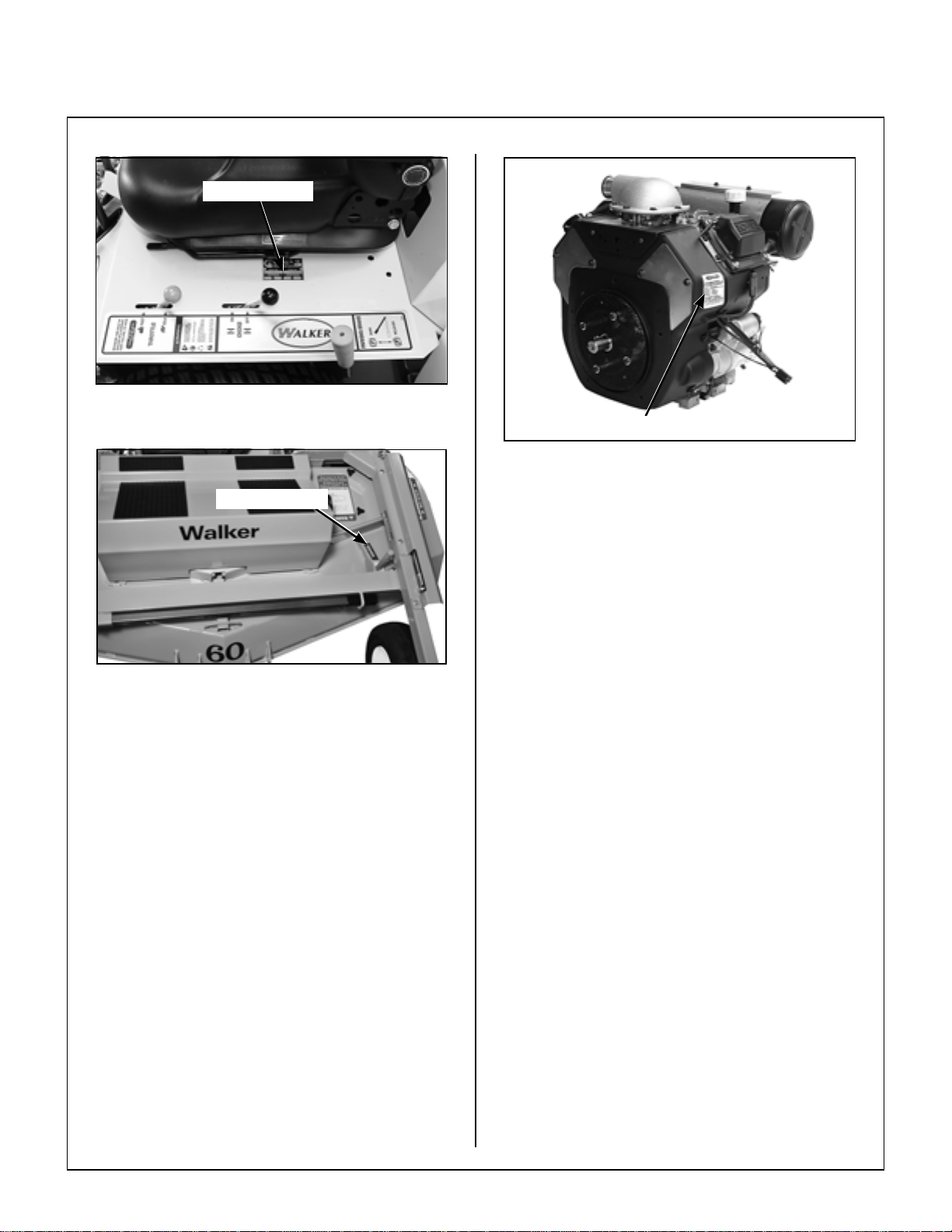
IDENTIFYING NUMBER LOCATIONS
The tractor serial number plate is affixed to the
tractor body just below the left rear corner of the
seat. The mower deck serial number plate is affixed
alongside the angle iron framing on the LH side of
the LH mower blade drive. Model and serial
numbers are helpful when obtaining replacement
parts and maintenance assistance. For ready
reference, please record these numbers in the
space provided.
Tractor Model No. _______________________
Tractor Serial No. _______________________
Deck Serial No. _______________________
• FORW ARD SPEED CONTROL (FSC) controls
the maximum forward speed of the tractor;
functioning as a cruise control.
• GROUND DRIVE refers to the dual transaxles
which drive the main wheels.
• LEFT HAND (LH) refers to the left-hand side of
the tractor when the operator is seated facing
forward in the tractor seat.
• POWER TAKE-OFF (PTO) transmits engine
power to run the cutter blades.
• RIGHT HAND (RH) refers to the right-hand side
of the tractor when the operator is seated fa cing
forward in the tractor seat.
• SIDE DISCHARGE (SD) mows but does not
collect the mowed material.
• STEERING LEVERS steer the tractor by con-
trolling the two transaxles.
Engine Model No. _______________________
Engine Serial No. _______________________
Date of Purchase _______________________
Fill In By Purchaser
1
Page 6
General Information
Serial Number
Tractor Serial Number Location
Serial Number
Engine Serial Number Location
Serial Number
Mower Deck Serial Number Location
ENGINE SERIAL NUMBER LOCATION
Refer to the engine manual th at accompanies this
manual for the location of the engine serial number.
For the mower model covered by this manual, an
engine manual is available from Kohler covering the
Kohler Command CH740 engine.
SERVICING OF ENGINE AND DRIVETRAIN COMPONENTS
The detailed servicing and repair of the engine and
transaxle are not covered in this manual. Only routine maintenance and general service instructions
are provided. For the service of these components
during the limited warranty period, it is important to
find a local, authorized servicing agent of the component manufacturer. Any unauthorized work
done on these components during the warranty
period may void the warranty. If you have any dif-
ficulty finding an authorized outlet or obtaining
warranty service, please contact our Service Department for assistance:
Walker Manufacturing Company
5925 E. Harmony Road
Fort Collins, CO 80528
1-970-221-5614
Service manuals are available for each of these
components from their respective ma nufacturers as
follows:
Kohler Engines Kohler Company
Kohler, WI 53044
800-544-2444
www.kohlerengines.com
Transaxles Hydro-Gear
1411 South Hamilton St.
Sullivan, IL 61951
2
Page 7

Specifications
MODEL MBSSD
ENGINE
Manufacturer/Model Kohler Command CH740, 2 Cyl. OHV (Air-Cooled)
Displacement 44.0 cu. in. (725 cc)
HP (@ 3600 RPM) 27.0
Max. RPM (No Load) 3600 ± 100
Governed RPM 3600 ± 100
Max. Torque [ft-lb (N
Idle RPM 1200 ± 75
Spark Plug Type Champion RC14YC
Spark Plug Gap .030 in. (0.76 mm)
Crankcase Capacity 1.9 qts (1.8 liters)
Crankcase Lubricant SG/SH/SJ or Higher Grade Oil Only with 10W-30 Viscosity
Oil Filter 12 050 01 5 (2-1/2)
Fuel Tank Capacity 10 Gallons (38 liters)
Fuel Automotive Grade Unleaded Gasoline (87 Octane) or Ga sohol
Cooling System Air Cooled
ELECTRICAL SYSTEM
Battery 12 Volt (340 CCA)
Charging System 15 Amp Alternator
Charging Output 15 Amp DC (Regulated)
·m) @ RPM] 42.7 (57.9) @ 3000
Above 0° F (-18° C) or 5W20 or 5W30 below 32° F (0° C)
Two In dependent Five (5) Gallon Tanks with Selector Valve
(Up to 10% Ethyl Alcohol, 90% Unleaded Gasoline by Volume)
System Polarity Negative Ground
Ignition Electronic Capacitive Discharge
Starter 12 Volt Electric Key an d Solenoid Operated
Interlock Switch Ignition Lockout by Seat Switch, Transmission Neutral and Blade Clutch
Circuit Breaker Manual Reset (30A)
TRANSMISSION
Manufacturer/Model Dual, Independent Hydro-Gear Integrated Transaxles
Steering Hand Lever Control / Individual Wheel
Forward Speed Control Precision Friction Lock Lever, Cruise Control, with Neutral-Park
Position
3
Page 8

Specifications
MODEL MBSSD
TRANSMISSION (continued)
Service Brake Dynamic Braking through Transaxles
Parking Brake (Internal) Mechanical Lockout for each Transaxle
Neutral Transmission Release by Manual Dump Valve
Final Drive Direct Drive Axle from Transaxle
Transmission Fluid
Factory Service 20W-50 Multi-Viscosity Motor Oil (Minimum SL Grade Oil)
Transmission Fluid Capacity 79 fl oz (2336 ml)
Transmission Cooling Cooling Fan Mounted on Drive Pulley
Ground Travel Speed
Forward m.p.h. (km/h)
Reverse m.p.h. (km/h)
BLADE DRIVE
(Single Lever Control)
0-9 (0-14) Infinitely Variable
0-5 (0-8) Infinitely Variable
PTO Shaft Sliding Spline Shaft with Two (2) High-Speed U-Joints
Blade Spindle Each Blade (3) Mounts Directly on Belt Driven Spindles
Blade Drive Clutch and Brake Manual Mechanical Clutch with Internal Brake
[Stops Blades within Five (5) Seconds of Disengagement]
Max. Blade Speed
[20-1/2 in. (52 cm) Blade] @
3600 RPM Engine
TIRE SIZE
Deck Caster Wheel 13 x 5.00-6 Pneumatic (4-Ply)
Drive 22 x 10.50-12 (4-Ply Low-Profile)
Rear 13 x 5.00-6 (4-Ply)
TIRE PRESSURE
Deck Caster Wheel 20 PSI (137 kPa)
Drive 15 PSI (103 kPa)
Rear
DIMENSIONS (Tractor and Mower)
Length
Width
60 in. (152 cm) SD Model
(with Deflector)
Height 43-1/4 in. (110 cm)
Wheel Base (Tractor) 42-5/8 in. (109 cm)
Tread Width (Tractor) 36-1/2 in. (93 cm)
3200 RPM
[18300 FPM (5578 m/min)]
20 PSI (137 kPa)
100-1/4 in. (255 cm)
62 in. (158 cm)
4
Page 9

Specifications
MODEL MBSSD
MOWER DECK
Width of Cut 60 in. (152 cm)
Cutting Height 1 to 5 in. (3 to 13 cm)
Height Adjustment 17 Positions - 1/4 in. (1 cm) Increments
Blade Size
60 in. (152 cm) SD Model 20-1/2 in. (52 cm) Three (3) Clockwise-Rotating Blades
Deck Suspension Torsion-Flex Frame with Caster Wheels and
CURB WEIGHT (Approximate)
Tractor Only 730 lb (331 kg)
SD Tractor and 60 in. SD Deck 1110 lb (503 kg)
DRIVE BELTS
Engine PTO Walker P/N 2230
Ground Drive Walker P/N 2248
Counterweight Springs
SEAT
FRAME/BODY CONSTRUCTION
Frame/Body 3/16 Plate Steel/14 Gauge Sheet Steel
Deck 11 Gauge Steel
Contour-Molded, with Nylon Backed Vinyl Cover and Integral
Foam Cushion (Suspension)
NOTE: The manufacturer reserves the right to make changes in specifications shown herein at any time
without notice or obligation.
5
Page 10
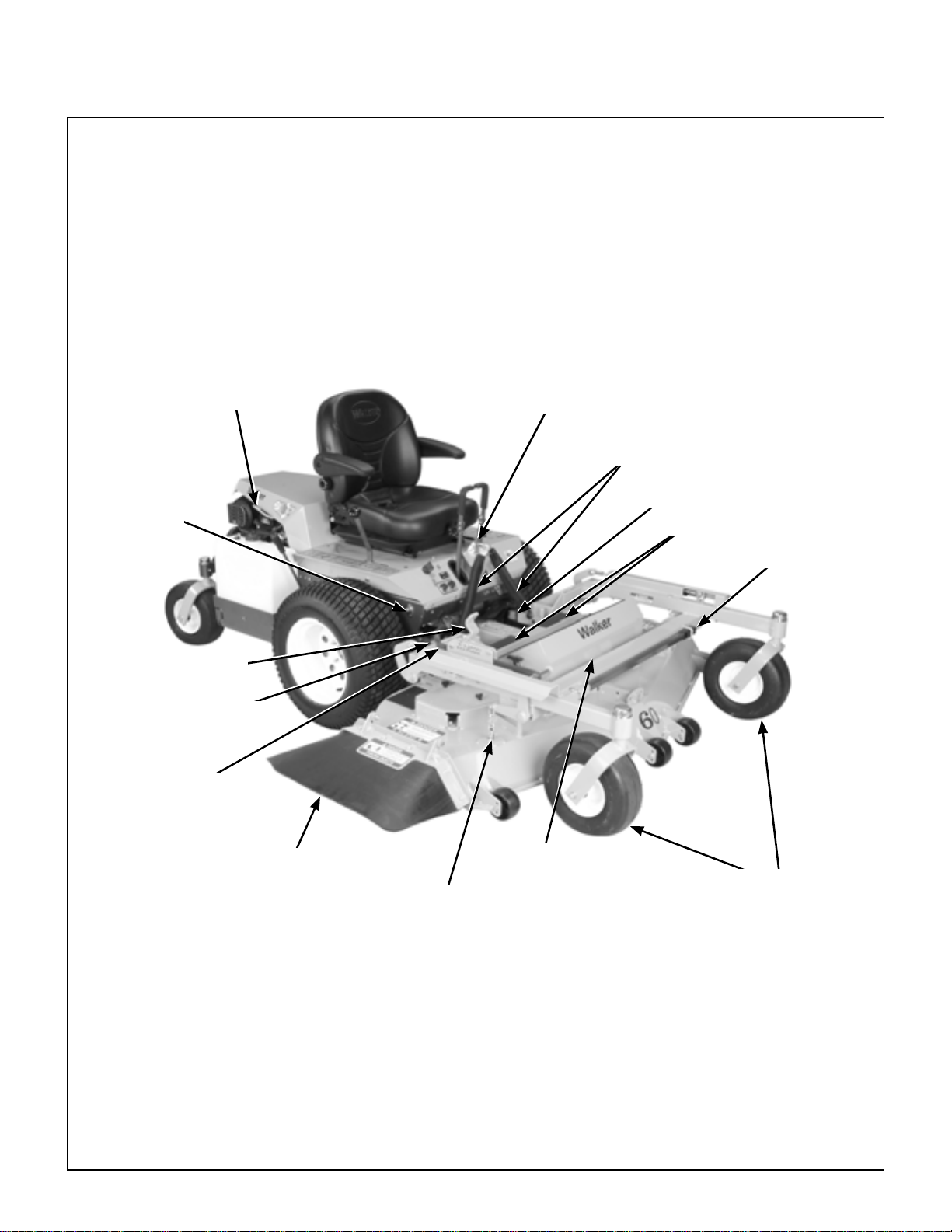
Component Identification
Body Lift
Handle
Forward Speed
Control (FSC)
Friction
Adjustment
NOTE: Control Identification
shown in Operating
Instructions section.
Tilt-Up Latch
Counterweight Spring and
Protective Cover
Deck Support
Arm
Footrests
Tilt Bar
Deck Handle
Deck Height
Adjustment Trigger
Deck Support Arm
Height Adjustment Arm
(Cutting Height Adjustment)
Discharge Shield
Deck
Deck Height
Lift Chain
Tilt-Up Hook
(not visible)
Deck
Caster Wheels
Front View and Right Side View
6
Page 11

Component Identification
Footrests
Footrest Catch
Assembly
Left Hand
Drive Wheel
Fuel Pickup
Line
Fuel Tank
and Cap
Tailpipe
Muffler
Spread
Tail Wheel
Battery
(not visible)
Rear View and Left Side View
7
Page 12
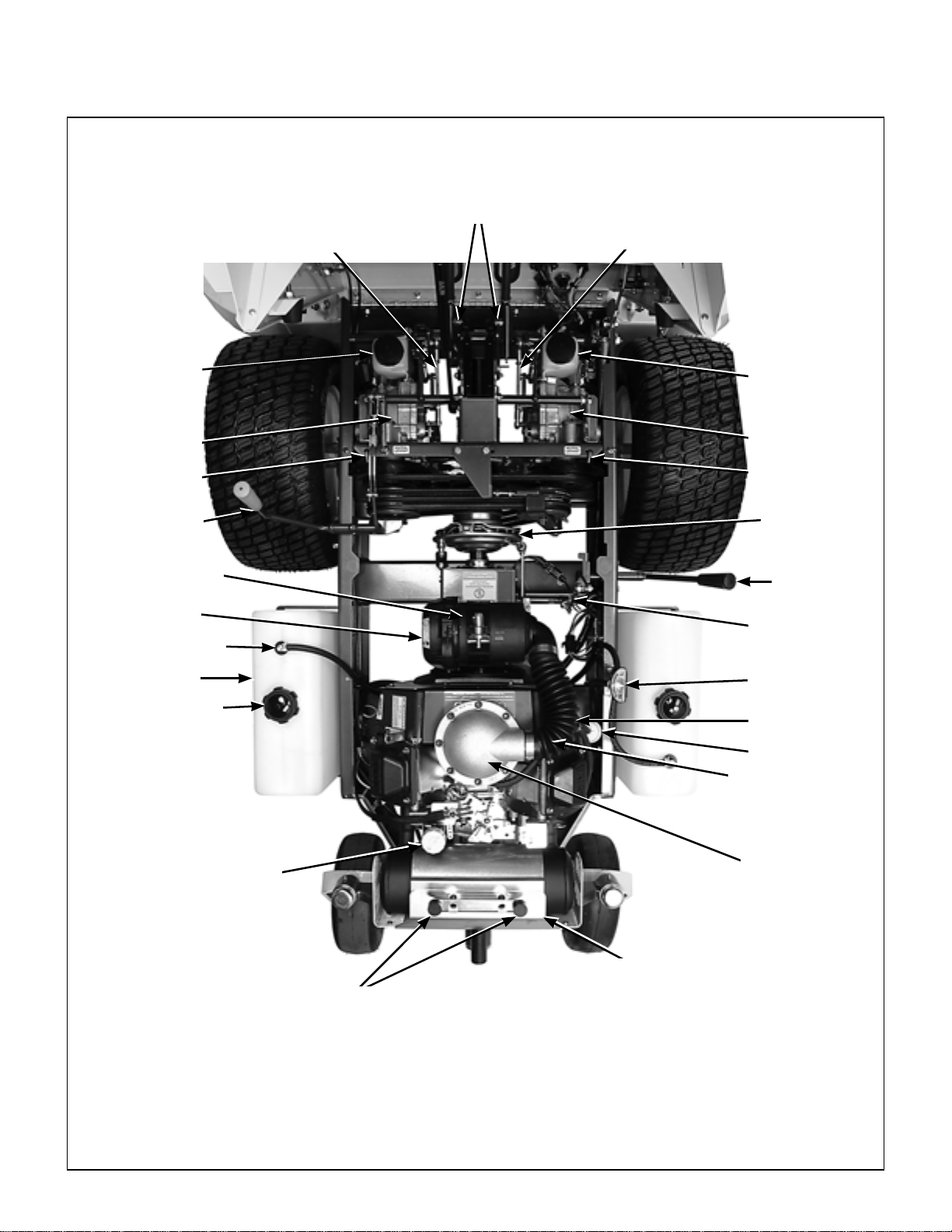
Component Identification
LH Transmission
Control Arm
Steerin g Levers
Dampeners
RH Transmission
Control Arm
LH Transaxle
Expansion
Reservoir
LH Transaxle
LH Transaxle
Lockout Rod
Parking Brake
Cummins/Fleetguard
OptiAir™ Air Cleaner
Air Filter
Cover
Fuel Pickup Line
Fuel Tank
Fuel Tank Cap
RH Transaxle
Expansion
Reservoir
RH Transaxle
RH Transaxle
Lockout Rod
Clutch
PTO Clutch
Lever
Parking Brake
Linkage
Fuel Selector
Valve
Fuel Pump
(not visible)
Fuel Filter
Air Intake Hose
Oil Fill/
Dipstick
Muffler Heat
Rubber Bumpers
(Body Support)
Top View (Body Raised)
8
Shield
Air Intake
Plenum
Page 13
Safety Instructions
Pay particular attention to any information labeled
DANGER, WARNING, CAUTION, IMPORTANT,
and NOTE in this manual.
When you see the Safety Alert Symbol ( ),
read, understand, and follow the instructions. Failure to comply with safety instructions may result in
personal injury.
The seriousness or degree of importance of each
type of information is defined as follows:
DANGER
An IMMEDIATE hazard that WILL result in
severe personal injury or DEATH, if warning is ignored and proper safety precautions are not taken.
WARNING
A POTENTIAL hazard that COULD result in
severe personal injury or DEATH, if warning is ignored and proper safety precautions are not taken.
Walker Manufacturing cannot predict every potentially dangerous situation. Therefore, items labeled
as such in this manual do not cover all conceivable
situations. Any person using proc edures, tools, or
control techniques not recommended by Walker
Manufacturing must take full responsibility for safety .
The Walker Rider Lawnmower has been designed
with many safety features to protect the operator
from personal harm or injury. However , it is necessary
for the operator to use safe operating procedures at
all times. Failure to follow safety instructions
contained in this manual may result in personal
injury or damage to equipment or property.
If you have any questions concerning setup, operation, maintenance, or safety, please contact your
authorized Walker Mower Dealer or call Walker
Manufacturing Company at (970) 221-5614.
BEFORE OPERATING
1. Read and understand the contents of this
Owner's Manual before starting and operating the machine. Become thoroughly familiar
with all machine controls and how to stop the
machine and disengage the controls quickly.
Replacement Owner's Manuals are available by
sending the Model and Serial Number to:
CAUTION
Possible hazards or unsafe practices that
MAY result in MODERATE personal injury
or property damage, or machine damage, if
warning is ignored and proper safety precautions are not taken.
IMPORTANT: Identifies mechanical information
demanding special attention, since it deals with the
possibility of damaging a part or parts of the
machine.
NOTE: Identifies information worthy of special
attention.
Walker Manufacturing Company
5925 East Harmony Road
Fort Collins, CO 80528
2. Never allow children to operate rider mower.
Do not allow adults to operate without proper
instruction.
3. Clear the area to be mowed of any foreign
objects which may be picked up and thrown by
cutter blades. Pick up all sticks, stones, wire,
and any other debris.
4. Keep everyone, especially children a nd pets, a
safe distance away from the area being mowed.
Do not mow with bystanders in the area.
5. Do not operate the machine barefoot or wearing
sandals, sneakers, tennis shoes, or similar lightweight footwear. We ar substantial protective
footwear.
9
Page 14

Safety Instructions
6. Do not wear loose fitting clothing that could get
caught in moving parts. Do not operate this
machine while wearing shorts; always wear
adequate protective clothing, including long
pants. Wearing safety glasses, safety shoes,
and a helmet is advisable and required by some
local ordinances and insurance regulations.
7. Prolonged exposure to loud noise can cause
impairment or loss of hearing. Operator hear-
ing protection is recommended. Wear a
suitable hearing protective device, such as earmuffs or earplugs.
8. Keep all protective shields and safety de-
vices in place. If a protective shield, safety
device, or decal is damaged, unusable, or missing, repair or replace it before operating the
machine.
9. Be sure interlock switche s are functioning
correctly, so the engine cannot be started unless the Forward Speed Control lever is in the
NEUTRAL-PARK position, and the PTO clutch
is in the DISENGAGED position. Also, the
engine should stop if the operator lifts off the
seat with either the Forward Speed Control
(FSC) out of the NEUTRAL-PARK position or
the PTO clutch in the ENGAGED position.
NOTE: There is a 1 to 1-1/2 second time delay
function on the seat switch to avoid engine
power interruption when driving over bumps.
10. Handle gasoline with care. Gasoline is highly
flammable and its vapors are explosive:
a. Use an approved fuel container.
b. Never add fuel to a running engine or hot
engine (allow hot engine to cool several
minutes).
11. Never attempt to make any adjustments
while the engine is running, except where specifically instructed to do so.
12. The electrical system battery contains sulfuric
acid. Avoid any contact with skin, eyes, and
clothing. Keep the battery and acid out of reach
of children.
WARNING
The engine exhaust from this product
contains chemicals known to the State of
California to cause cancer, birth defects
or other reproductive harm.
OPERATING
1. Operate the mower only in daylight or in good
artificial light with good visibility of the area being
mowed.
2. Sit on the seat when starting the engine and
operating the machine. Keep feet on the deck
footrests at all times when the tractor is moving
and/or mower blades are operating. Never
operate the tractor without deck or implement installed.
3. For a beginning operator, learn to steer
(maneuver) the tractor with a slow engine
speed before attempting any mowing operation. Be aware that, with the front mounted
mower configuration, the back of the tractor
swings to the outside during turns.
4. Remember, for an emergency stop, the forward
motion of the tractor can always be stopped by
pulling the Forward Speed Control (FSC) into
the NEUTRAL-PARK position.
10
c. Keep matches, cigarettes, cigars, pipes,
open flames, or sparks away from the fuel
tanks and fuel container.
d. Always fill the fuel tank(s) outdoors using
care. Fill to about one inch from the top of
the tank. Use a funnel or spout to prevent
spilling.
e. Replace the machine fuel cap(s) and con-
tainer cap securely and clean up any spilled
fuel before starting the engine.
5. In case the transmission drive belt breaks during
operation, and if the machine is on a slope, the
machine will freewheel down the slope. To
maintain control, immediately (1) Release the
steering levers and simultaneously (2) Move the
FSC to the NEUTRAL-PARK position. When
the machine is stopped or moving slowly,
engage the parking brake.
NOTE: This is exactly the same procedure
used to normally stop and park the machine.
Page 15

Safety Instructions
6. Disengage the blade clutch and put the FSC in
the NEUTRAL-PARK position before starting
the engine (an ignition interlock switch normally
prevents starting of the machine if these controls
are in the OPERATING position).
7. Do not run the engine in a confined area
without adequate ventilation. Exhaust fumes
are hazardous and can be deadly.
8. Do not carry passengers - maximum seating
capacity is one (1) person.
9. Watch for holes, rocks, and roots in the terrain
and for other hidden hazards. When mowing tall
grass, mow higher than desired to expose any
hidden obstacles. Then, clean the area and
mow to the desired height.
10. Avoid sudden star ts or stops. Before backing
the machine up, look to the rear to be sure no
one is behind the machine. Watch carefully for
traffic when crossing or working near r oadways.
11. Disengage the blade drive when transporting
the machine across drives, sidewalks, etc. Never
raise the mower deck while blades are
rotating.
12. The maximum recommended side slope
operating angle is 20 degrees or 33% grade.
When operating the machine on a slope, reduce
speed and use caution to start, stop, and
maneuver. To prevent tipping or loss of control
of the machine, avoid sharp turns or sudden
changes in direction.
15. When using the tilt-up deck, observe the fol-
lowing recommendations:
a. Do not move tractor with deck in tilt-up
position.
b. Never tilt body forward with deck in tilt-up
position.
16. In case of a clogged or plugged mower deck:
a. Disengage the blade clutch (PTO), set the
parking brake, and turn the engine off before
leaving the seat.
b. LOOK to make sure blade drive shaft move-
ment has stopped before trying to unclog
the system.
c. Disconnect the spark plug wires.
d. Never place hands under the deck - use a
stick or similar tool to remove clogged ma-
terial.
17. If the cutting blades strike a solid object or the
machine begins to vibrate abnormally,
immediately disengage the blade clutch
(PTO), stop the engine, and wait for all
moving parts to stop. To prevent accidental
starting, disconnect the spark plug wires.
Thoroughly inspect the mower and r epair any
damage before restarting the engine and
operating the mower. Make sure cutter blades
are in good condition and blade bolts are
torqued to 64 ft-lb (86.8 N
·m).
13. Never adjust cutting height while the mower
is moving. Before adjusting cutting height or
servicing, move the Forward Speed Control
(FSC) into the NEUTRAL-PARK position,
engage the parking brake, and disengage the
blade clutch (PTO ). Tractor should not be mov-
ing while adjusting cutting height.
NOTE: The clutch brake should normally stop
drive line rotation within five (5) seconds of disengaging the PTO clutch.
14. Do not operate with the grass deflector
chute removed. Keep the deflector in the lowest possible position.
18. Do not touch th e engine or muffler while the
engine is running or immediately after stopping the engine. These areas may be hot
enough to cause serious burns.
19. When leaving the machine unattended, disen-
gage the blade clutch (PT O), stop the engine,
and remove the key.
11
Page 16

Safety Instructions
MAINTENANCE
1. To prevent accidental starting of the engine
when servicing or adjusting the machine,
remove the key from the ignition switch and
disconnect the spark plug wires.
2. To r educe fire hazards, keep the engine free of
grass, leaves, excessive grease, and dirt.
3. Keep all nuts, bolts, and screws tight to ensure
the machine is in a safe, working condition.
Check the blade mounting bolts frequently , making sure they are tight.
4. Perform only maintenance instructions de-
scribed in this manual. Unauthorized maintenance operations or machine modifications
may result in unsafe operating conditions.
5. If the engine must be running to perform a maintenance adjustment, keep hands, feet, and
clothing away from moving parts. Do not wear
jewelry or loose clothing.
6. Always use the proper engine service
manual when working on the engine.
Unauthorized maintenance operations or
modifications to the engine may result in
unsafe operating conditions.
11. Use care when cha rging the battery or performing maintenance on the battery and
electrical system:
a. Make sure the battery charger is unplugged
before connecting or disconnecting cables
to the battery.
b. Charge the battery in a well-ventilated
space, so gases produced while charging
can dissipate. Make sure the battery vents
in the caps are open.
c. Keep sparks, flames, and smoking materi-
als away from the battery at all times. To
avoid sparks, use care when removing battery cables from posts.
d. Disconnect both battery cables before
unplugging any wiring connectors or
making repairs on the electrical system.
IMPORTANT: Keep all applicable manuals
immediately accessible to anyone who may
operate or service this machine.
7. Altering the equipment or engine in any manner
which adversely affects its operation, performance, durability , or use will VOID the warranty
and may cause hazardous conditions.
8. Never attempt to disconnect any safety devices
or defeat the purpose of these safety devices.
9. Do not change the engine governor settings or
overspeed the engine. The governor has been
factory-set for maximum-safe engine operating
speed.
10. Use genuine factory replacement part s. Substitute parts may result in product malfunction
and possible injury to the operator and/or
others.
12
Page 17
Safety Instructions
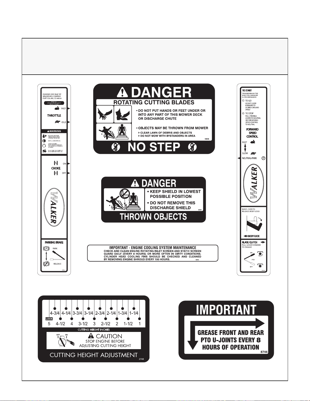
SAFETY, CONTROL, AND INSTRUCTION DECALS
Safety, Control, and Instruction Decals are installed on the machine;
if any are missing, illegible, or damaged, a replacement should be ordered and installed before
putting the machine into operation. The Decal Part Number is listed below and in the Parts Section.
Each End of Mower Deck (5808)
LH Fender (2802-1)
Deck Carrier Frame (2748)
SD Deck Discharge Shield (5848)
Engine Shroud (5855)
RH Fender (2802-2)
PTO Guard (8746)
13
Page 18
Safety Instructions
DRIVE BELT
WALKER P/N 2731
CARLISLE P/N R3VX1250-2
BELT TWIST
DRIVE PULLEY
WALKER P/N 2240-1
BELT TWIST
2749
BLADE PULLEY
WALKER P/N 2240
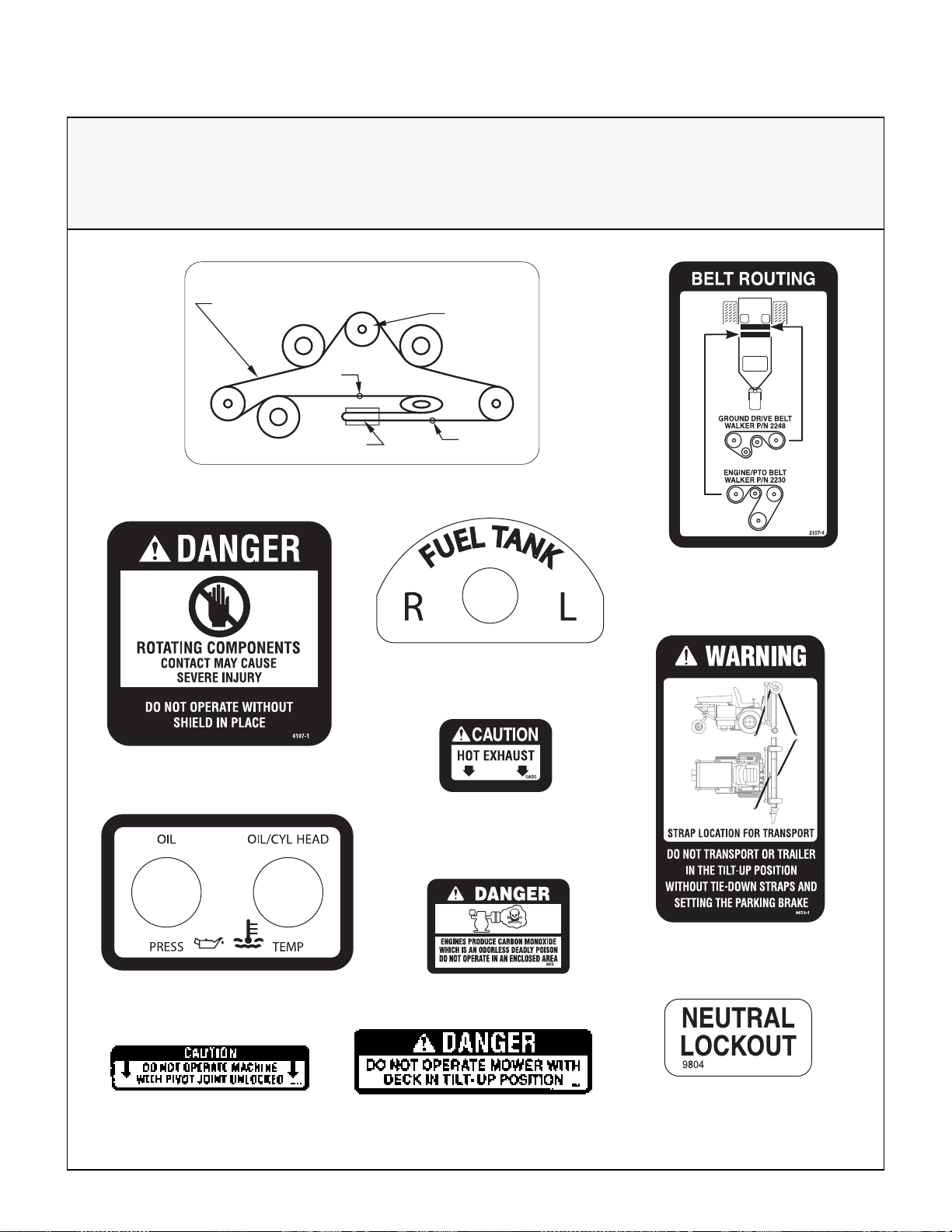
SAFETY, CONTROL, AND INSTRUCTION DECALS
Safety, Control, and Instruction Decals are installed on the machine;
if any are missing, illegible, or damaged, a replacement should be ordered and installed before
putting the machine into operation. The Decal Part Number is listed below and in the Parts Section.
BELT ROUTING
DRIVE BELT
WALKER P/N 2731
CARLISLE P/N R3VX1 250-2
BELT TWIST
BLADE PULLEY
WALKER P/N 2240
DRIVE PULLEY
WALKER P/N 2240-1
Deck Housing (2749)
On Precleaner Mount (4107-1)
BELT TWIST
2749
Rear Body, Underside (2107-4)
On Trans fer Mount (2010-4)
Rear Body,
Above Muffler (5805)
14
Front Body Adjacent to
RH Steering Lever (2807-1)
Deck Carrier Frame (8653)
Deck Housing (8653-1)
On Engine (6810)
Center Body Behind Transaxles
Deck Carrier Frame (8647)
(9804)
Page 19
Assembly Instructions
SETUP INSTRUCTIONS
Walker Mowers are shipped partially assembled to
our distribution network, and are typically assembled
by the selling dealer. For any additional assembly
besides the following, contact your Walker dealer.
Battery Service
Raise mower body up for battery access. Check the
battery for electrolyte level and charge. The
electrolyte level should be at the bottom of the vent
wells [1/4 to 1/2 in. (6 to 13 mm) above plates]. If the
specific gravity is less than 1.225, the battery needs
charging. If the battery has been shipped dry, or is
wet but needs service, refer to the following
instructions.
IMPORTANT: Make sure battery is securely
mounted in the frame. A loose battery may cause
damage to the case resulting in acid leakage and se vere damage to the machine. A hazard may be created by damage to critical working parts and safety
systems.
Wet Battery Service
Dry Battery Service
DANGER
Activating a battery can be dangerous.
The battery should be taken to a reliable
service station, battery store, or power
equipment dealer where a trained technician can activate the batter y safely. DO
NOT attempt to activate the battery unless
you are experienced in battery service
work. The following activation and charging instructions are provided for u se b y a
trained battery technician.
DANGER
Battery electrolyte is a poisonous and corrosive sulfuric acid solution.
• Avoid spillage and contact with skin,
eyes, and clothing - causes severe burns.
If the battery has been shipped wet, but the electrolyte
level is low or the battery needs to be charged then:
1. Fill each battery cell with drinking water to the
bottom of the vent wells.
2. Charge battery. Refer to Battery Charging in
this section.
• To prevent accidents, wear safety gog-
gles and rubber gloves when working with
electrolyte.
• Neutralize acid spills with baking soda
and water solution.
T o fill (activate) battery with electrolyte (if battery has
been shipped dry):
1. Remove the battery hold-down bar, disconnect
the battery cables and lift the battery out of the
tray.
IMPORTANT: Battery must be removed from
the mower before filling with electrolyte.
IMPORTANT: Obtain and use only battery
grade sulfuric acid electrolyte with a 1.265 specific gravity to activate the battery . DO NOT use
water or any other liquid during initial activation.
2. Remove the filler caps and carefully fill each cell
until the electrolyte is just above the plates.
3. After the battery is filled with electrolyte, replace
the filler caps and charge the battery. Refer to
Battery Charging.
15
Page 20
Assembly Instructions
Battery Charging
DANGER
BA TTERIES PRODU CE EXPLOSIVE GASES
• Charge the battery in a well-ventilated
area, so that gases produced while charging can dissipate.
• Keep sparks, fla mes, and smoking mate-
rials away from the battery at all times.
• Make sure the battery cap vents are open
after the battery is filled with acid (check
manifold vent on each cap).
Deck Caster Wheel Installation
• Make sure the battery charger is unplug-
ged before connecting or disconnecting
cables to the battery.
1. Charge the battery at 15 amps for 10 minutes.
DO NOT exceed 20 amps maximum recommended charging rate. Charge until specific
gravity is at least 1.250. Total charging time
should not exceed one (1) hour.
2. After charging the battery , adjust the e lectrolyte
level to the bottom of the vent wells [1/4 to 1/2 in.
(6 to 13 mm) above the plates].
IMPORTANT: DO NOT overfill the battery.
Electrolyte will overflow through the vented caps
onto parts of the machine and WILL result in
severe corrosion.
3. Install battery.
Mower Deck Assembly
Deck Caster Wheels Installation
Deck Discharge Shield Installation
Attach the deck side discharge shield by positioning
the shield hinge lug in front of the deck mount and
fastening with two 3/8-16 x 1-1/4 in. bolts, 3/8-16
ESNA nuts, and 3/8 in. wave spring washers. The
wave washers fit between the two hinging surfaces.
Tighten the nuts until the shield moves freely but is
not loose.
WARNING
DO NOT operate the machine without the
grass deflector chute attached and in the
lowest possible position.
Attach Shield
16
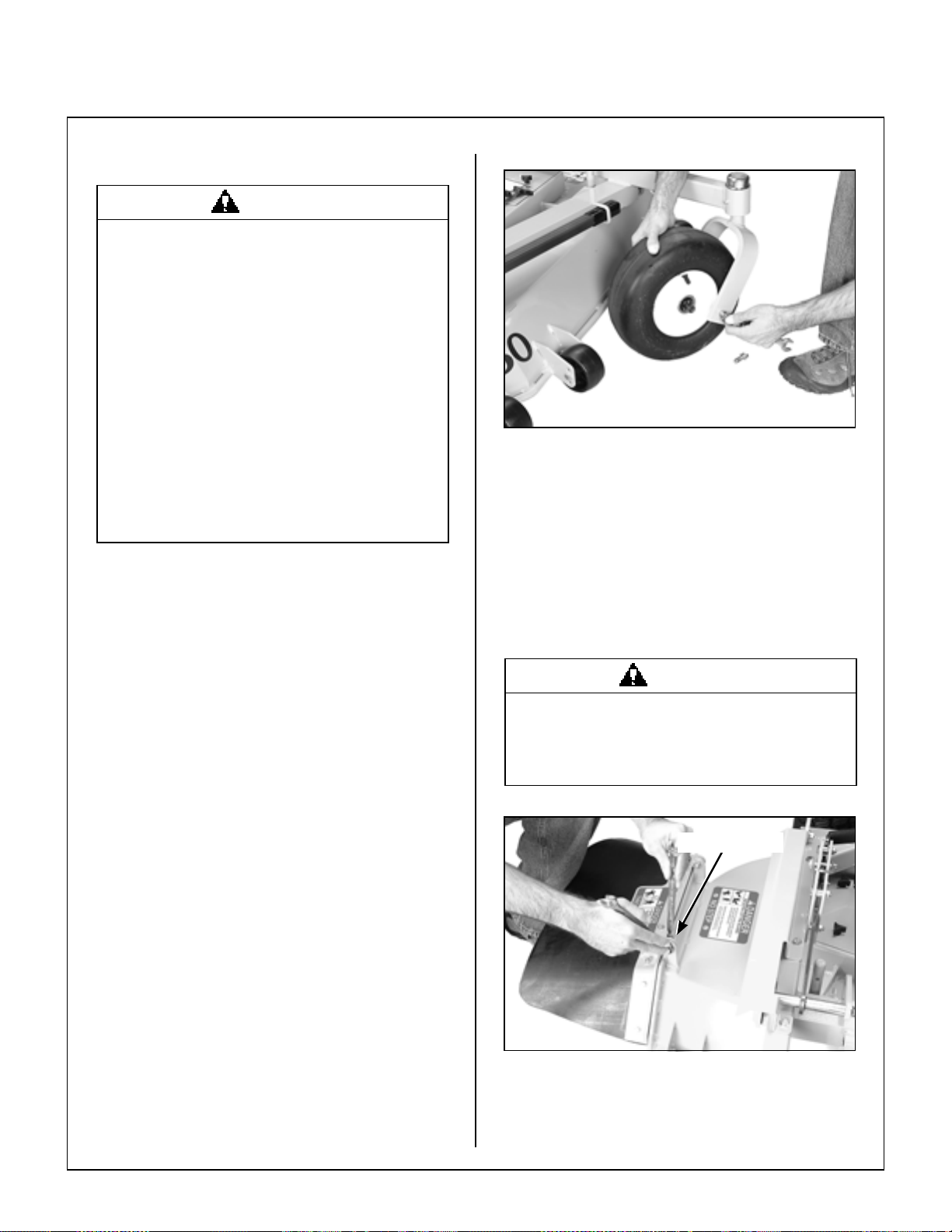
1. Remove the bolts and washers from each deck
caster wheel.
2. Install wheel on fork using bolts and washers.
NOTE: Valve stem and grease zerk should
face to the inside of machine.
3. Tighten the bolts and washers.
Deck Discharge Shield Installation
Page 21
Assembly Instructions
PTO Shaft Guard Installation
Position the shaft guard as shown and mount with
two 1/4-20 x 1/2 in. bolts.
Carrier Frame
Tube Sockets
Attach
Guard
PTO Shaft Guard Installation
Tilt-Up Roller Wheel Installation
Mount the two (2) tilt-up roller wheels on the bracket s
on the rear skirt of the deck housing using the
P/N 8490 axle bolt, 3/8 in. wave s pring wash er and
3/8-16 in. Whiz locknut. Tighten the axle bolt until the
wheel rolls freely, but is not loose.
Mower Deck Installation on Tractor
Deck Installation
1. Lightly grease each deck support arm ( 2) on the
tractor. Refer to Mower Deck Inst allation photo
for location of deck support arm.
2. Engage the LH deck carrier frame tube socket
first on the tractor support arms and then the RH
tube socket, slide the deck onto the support arms
approximately 3 in. (76 mm).
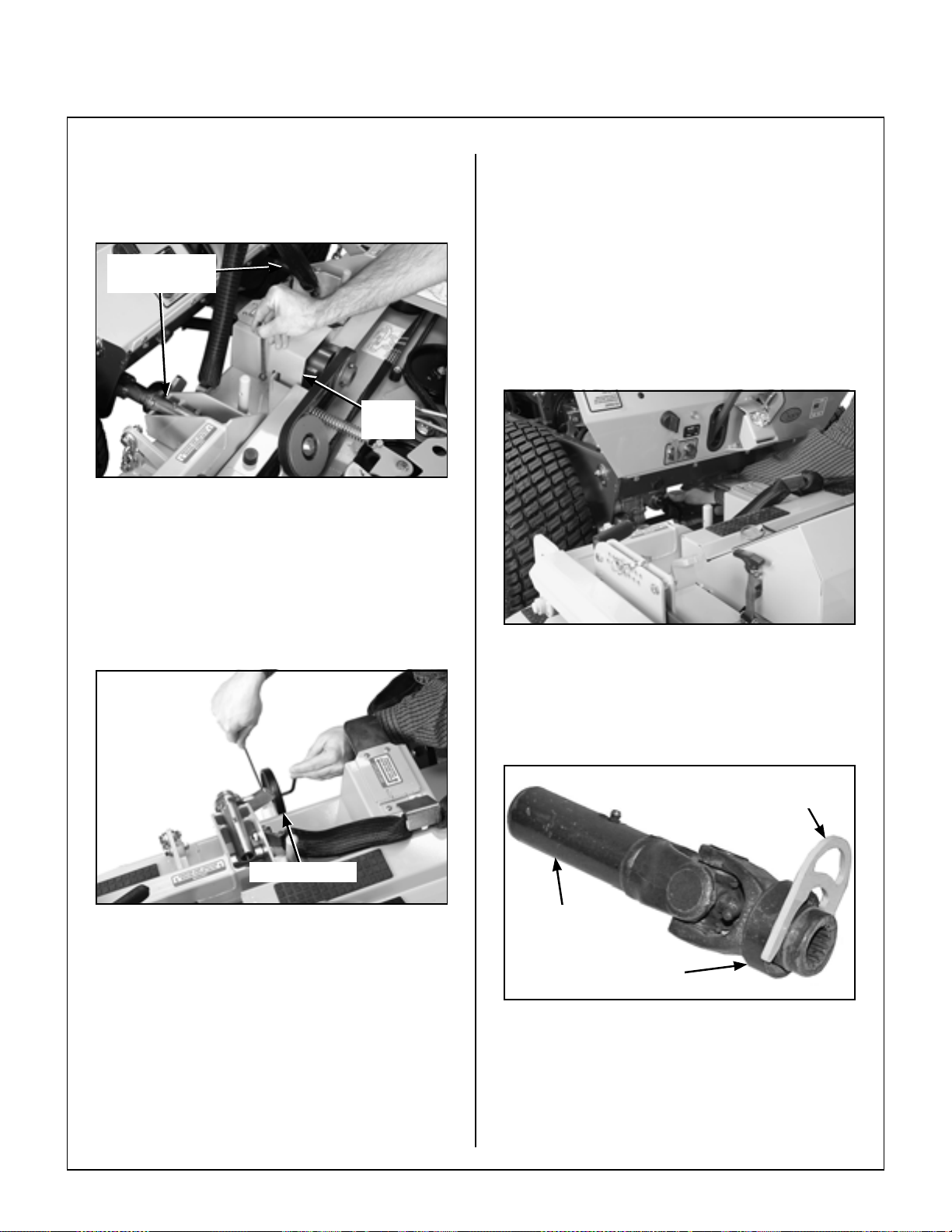
Retract Coupler Ring
Roller Wheel
Roller Wheel Installation
3. Retract spring-loaded coupler ring on the PTO
Tube (provided in Owner’s Packet) and insert
coupler tool. Refer to Quick Coupler Installa-
tion Tool photo.
Quick Coupler
Installation Tool
PTO Tube
Pull Back Spring-Loaded
Coupler Ring
Quick Coupler Installation Tool
17
Page 22
Assembly Instructions
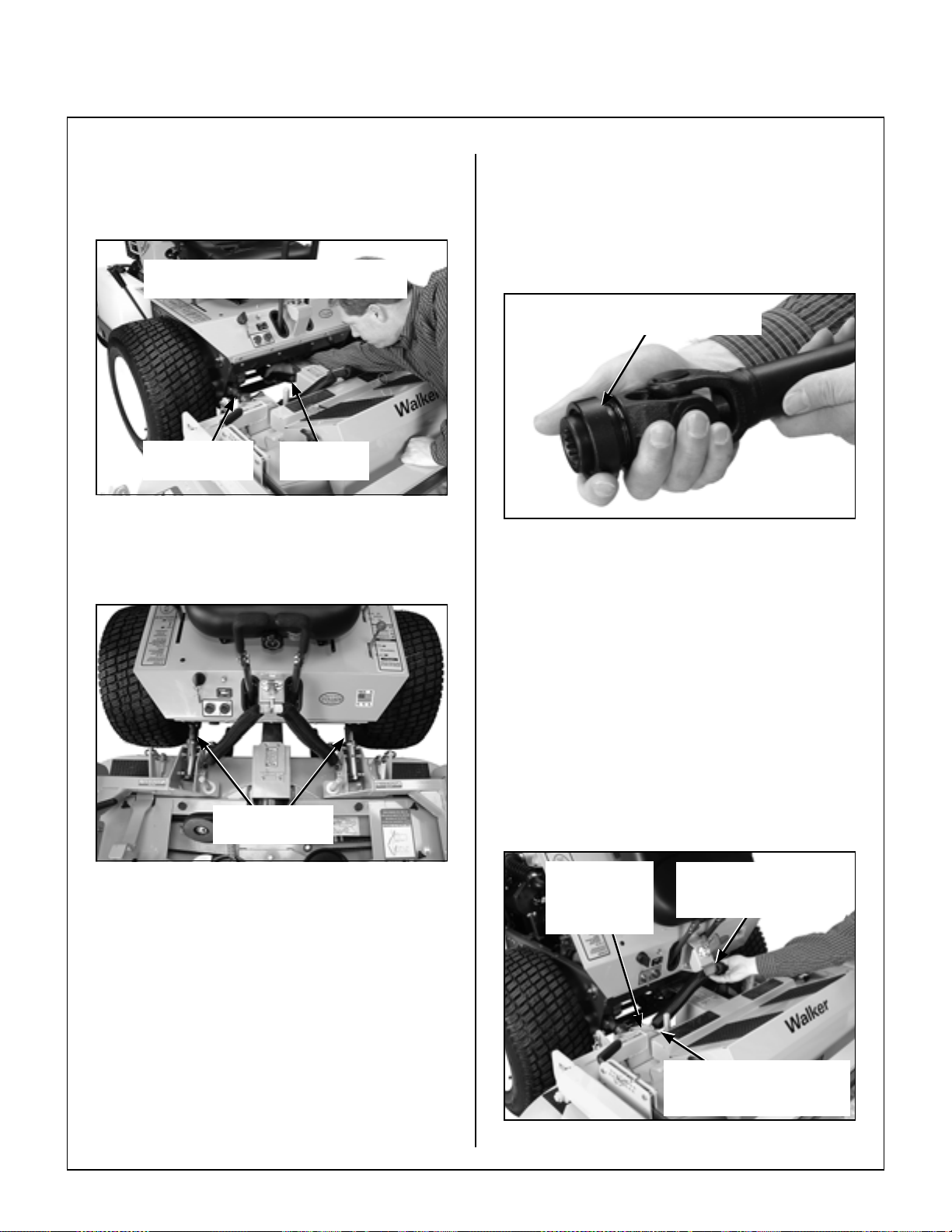
4. Reaching under the tractor , join the PT O tube to
the PTO shaft (align arrow decals). Slide the
PTO tube onto the spline shaft on the tractor
PTO drive shaft.
Arrows on Shaft and Tube
(used to align when sliding together)
Grease Deck
Support Arms
Mower Deck Installation (PTO Shaft Connection )
5. Slide the deck the rest of the way on the deck
arms.
PTO
Connection
IMPORTANT: To prevent damage to the
mower, make sure the PTO shaft assembly is
securely locked on the tractor, with the locking
balls fully seated in the groove and the ring in the
full forward position (refer to the Coupler Ring
“Locked” Position photo). After installation,
pull on the shaft to check for security.
Spring-Loaded Coupler Ring
In Fully Forward Position
Coupler Ring “Locked” Position
8. Raise the mower body (instead of lifting the
front of deck) and clip the counterweight springs
to the receptacle on front of body. Lower the
body to tension the springs. (Refer to Deck
Counterweight Spring Installation Photo.)
Deck Support
Arms
Mower Deck Installation
6. Install the lynch pin through the hole on the end
of each support arm to lock the deck in place
(refer to Deck Counterweight Spring Installa-
tion photo). Two (2) lynch pins are included in
the owner's packet of materials.
7. Remove Installation Tool from coupler ring and
make sure the ring has “snapped” securely on
the spline shaft.
IMPORTANT: DO NOT operate tractor with
Quick Coupler Installation Tool installed.
9. With the counterweight springs connected, the
weight on the deck caster wheels should be 15
to 25 Ib (6.8 to 11.3 kg). Check this weight by lifting on the front of the deck carrier frame. If
required, the spring tension can be adjusted by
tightening or loosening the elastic stop nuts located underneath the lower spring hook. Refer
to Deck Counterweight Spring Installation
photo.
Lynch Pins
Lock Deck On
Support Arms
(not visible)
Deck Counterweight Spring Installation
Counterweight Springs
Clip Onto Body
With Body Tilted Up
Spring Tension Adjustment
Nut Located Under Lower
Spring Hook (not visible)
18
Page 23
Assembly Instructions
Deck Leveling
1. Position mower on a smooth, level surface. Set
the cutting height to the highest position - 5 in.
(127 mm) - for easy access under the deck to
measure blade height. Refer to ADJUSTING
CUTTING HEIGHT in Operating Instructions.
NOTE: A block of wood cut 5 in. (127 mm) high
is a convenient gauge to measure blade height
above ground during the leveling process.
WARNING
The machine must be shut off during this
procedure.
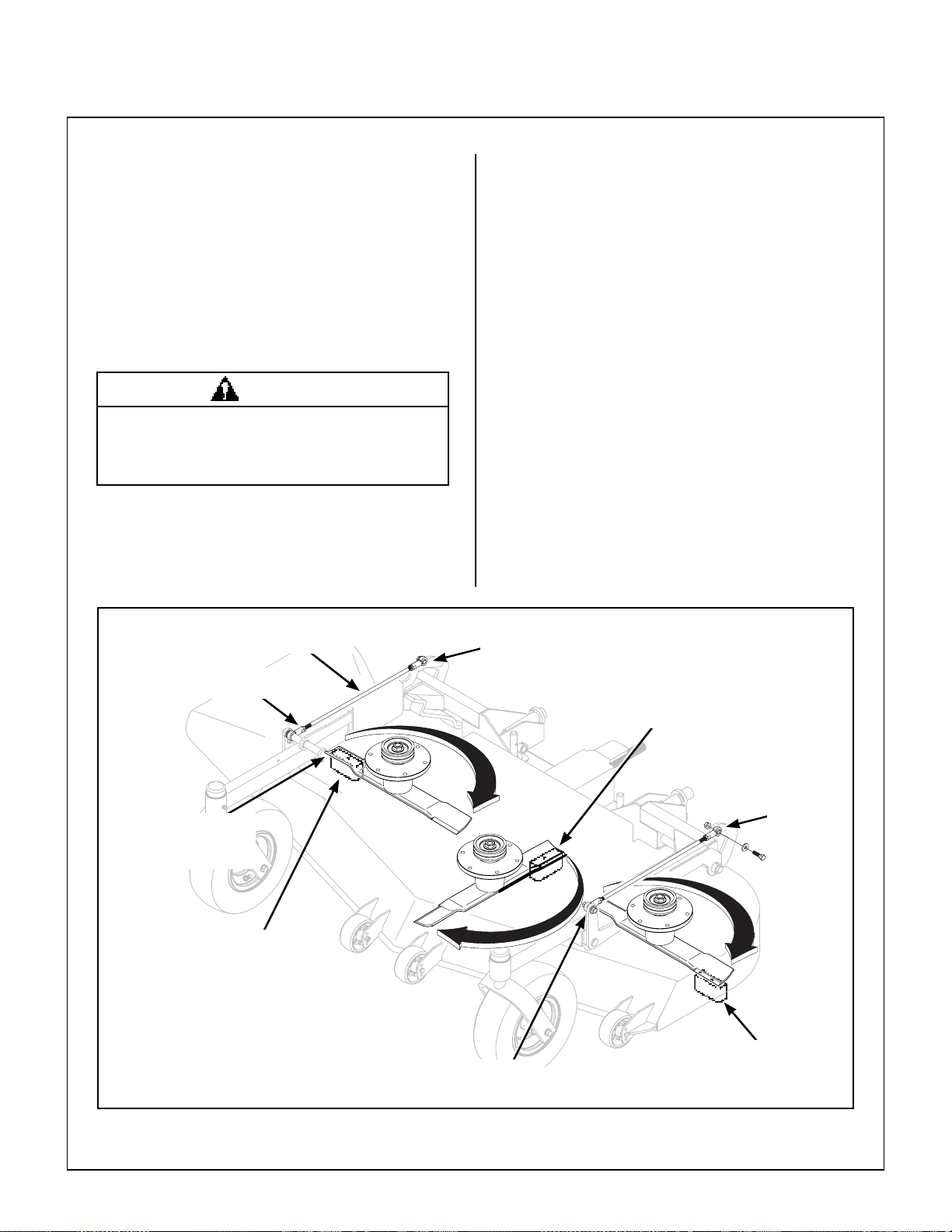
2. Check the side-to-side level. Rotate the outside blades sideways and measure the
distance from blade tip to ground on each side.
If measurements vary more than 1/8 in. (3 mm),
adjust the height adjustment rod on the high side
to level the deck.
3. Check the front-to-rear level. Rotate the cen-
ter blade to point forward. Measure the
distance from blade tip to ground on the front
and rear . The rear of the blade should be 1/8 to
1/4 in. (3 to 6 mm) higher than the front of the
blade; remove the chain from the deck height
adjuster clevis and adjust equally to achieve at
least 1/8 in. (3 mm) difference. Reinstall
chains.
NOTE: The mower deck and support frame are
jig welded; within normal tolerances, very little, if
any , adjustment s should be required to level the
deck. Tire pressure will influence the levelness
of the deck. Check the tire pressure as a possible cause of the deck not being level.
Height Adjustment
Front
Rod End
Should not vary more
than 1/8 in. (3 mm)
side-to-side
5 in. (127 mm)
Wood Block
Rod
Rear
Rod End
Front
Rod End
Should be 1/8 in. (3 mm)
to 1/4 in. (6 mm) higher
at the rear of the blade
Rear
Rod End
5 in. (127 mm)
Wood Block
Deck Leveling
19
Page 24
Assembly Instructions
PREOPERATING CHECKLIST
Before operating the mower for the first time, and as
a routine before daily operations, it is important to
make sure the mower is properly prepared and ready
for operation. The following is a list of items to be
checked. (For a mower with frequent operation,
some of these items will not need to be checked every
day , but the operator should be aware of the condition
of each.)
For proper fuel and lubricants refer to Specifications.
FILL FUEL TANK(S)
Fill the fuel tank(s) using clean, fresh, automotive
grade unleaded gasoline (87 octane rating minimum) or gasohol (up to 10% ethyl alcohol, 90%
unleaded gasoline by volume). See engine manual
for complete fuel recommendations.
DANGER
Handle gasoline with care. Gasoline is highly flammable and its vapors are explosive.
Use safe refueling procedures:
• DO NOT fill fuel tank(s) with the engine
running.
• If the engine is hot, allow to cool before
refueling.
• Use an approved fuel container.
• Fuel the mower outdoors.
CHECK ENGINE CRANKCASE OIL LEVEL
Check the engine crankcase oil level before use and
after each 8 hours of continuous operation. Refer
to LUBRICATION for Checking Engine Crankcase
Oil Level in Maintenance Instructions.
CHECK AND SERVICE ENGINE AIR CLEAN-
ER SYSTEM
• Check air restriction gauge to make sure there is
no red indication showing.
• Check condition, cleanliness, and security of the
complete air cleaner system (inspect air filter
every 100 hours). For detailed procedures,
refer to CLEANING the Engine Air Cleaner
System in Maintenance Instructions.
CHECK ENGINE COOLING SYSTEM
Check that the engine cooling air intake screen is
free of obstruction by grass clippings or debris and
clean if required. Also, cylinder head cooling fins
should be inspected and cleaned if any build-up of
debris is noted [remove two (2) cylinder head access panels to inspect and clean].
CHECK SECURITY OF DRIVE TIRE MOUNT-
ING NUTS
The eight (8) Drive Tire mounting nuts should each
be torqued to 75-85 ft-lbs. (101.7-115.2 N
INSPECT FOUR (4) DRIVE BELTS
·m).
20
• DO NOT smoke while refueling.
• Avoid spilling fuel; use a funnel or spout.
• DO NOT overfill the fuel tank(s); fill up to
about 1 in. (25 mm) below the top of tank.
IMPORTANT: DO NOT permit dirt or other foreign
matter to enter the fuel tanks. Wipe dirt from around
the filler cap(s) before removing. Use a clean fuel
storage container and funnel.
IMPORTANT: DO NOT mix oil with gasoline.
Always use fresh, automotive gr ade unleaded gasoline or gasohol. DO NOT use premium, white, or
high-test gasoline. DO NOT us e additives, such as
carburetor cleaners, deicers, or moisture removing
agents. DO NOT use gasoline blended with methyl
alcohol.
Engine/PTO and Ground Drive.
CHECK HYDROSTATIC TRANSAXLE OIL
LEVEL
Refer to LUBRICATION for Transaxle Lubrication
in Maintenance Instructions.
CHECK TIRE PRESSURE
Deck Caster Wheel = 20 PSI (137 kPa)
Drive = 15 PSI (103 kPa)
Rear = 20 PSI (137 kPa)
Page 25
Assembly Instructions
CHECK FUNCTION OF SAFETY INTERLOCK
SWITCHES
CAUTION
Refer to Operating Instructions to check for proper
operation of safety switches, both during engine
starting and with the operator leaving the seat with
tractor moving forward or with mower blades engaged.
CHECK AND CLEAN GRASS BUILDUP
UNDERNEATH MOWER DECK
Refer to CLEANING the Grass Buildup in Mower
Housing in Maintenance Instructions for deck tilt-up
and deck cleaning information.
DANGER
Never operate cutter blades with deck in
raised position because it is hazardous.
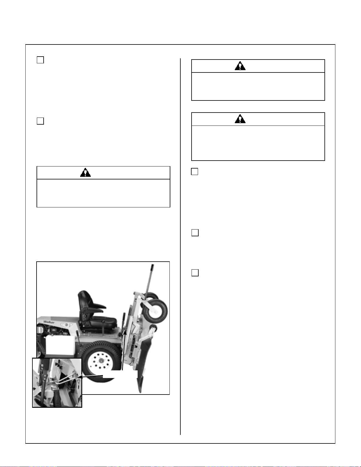
The tilt-up deck can be secured in the raised po sition
by disengaging the locking arms on each side of the
carrier frame and inserting the deck hook into the tiltup latch on the tractor body. Before operating the
tractor, make sure to re-engage the locking arms after
lowering the deck to the normal operating position.
Do not operate machine with locking
arms disengaged.
DANGER
Do not operate the mower with deck in tiltup position. Do not move the tractor with
the deck in the tilt-up position.
CHECK MOWER BLADE CONDITION, SHARP-
NESS, BALANCE, AND SECURITY OF
MOUNTING
The blade mounting bolt should be tightened to 64 ft-lb
(86.8 N
CHECKING/SERVICING for Sharpen Mower
Blades in Maintenance Instructions.
Refer to ADJUSTING CUTTING HEIGHT in Operating Instructions.
·m). If blade sharpening is required, refer to
ADJUST MOWER CUTTING HEIGHT, IF RE-
QUIRED
Tilt-Up Latch
Deck Secured in Tilt-Up Position
PERFORM ANY ADDITIONAL PROCEDURES
called for on the MAINTENANCE SCHEDULE
CHART in Maintenance Instructions.
21
Page 26
Operating Instructions
CONTROL IDENTIFICATION, LOCATION, AND FUNCTION
CAUTION
Before operating the mower, become familiar with the location and function of all
operator controls. Knowing the location,
function, and operation of these controls
is important for safe and efficient ope ration of the mower.
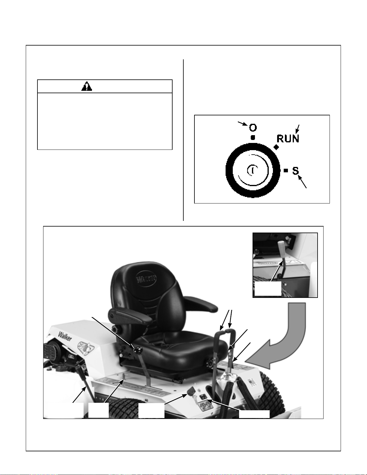
Ignition Switch
The ignition switch is located on the right fro nt of the
body and is used to start and stop the engine. The
switch has three positions: “O” is the OFF position,
RUN is the position the key returns to after starting,
and “S” is the START position. When starting the
engine, turn the key clockwise to the “S” position. Do
not hold the key in the “S” position long er than 10
seconds. If the engine does not start, return the key
to the “O” position for at least 60 seconds before
making a restart attempt. Prolonged cranking can
damage the starter motor and shorten battery life.
Release the key when the engine starts, and it will
return to the RUN position. T o stop the engine, rotate
the key counterclockwise to the “O” position.
OFF
Ignition Switch
ON
START
Forward Spe ed
Control (FSC)
Blade Clutch
(PTO)
Body
Latch
Ignition
Switch
Operating Controls
Parking
Brake
Steering
Levers
Choke
(not visible)
Throttle
Hourmeter
22
Page 27

Operating Instructions
Engine Choke
The choke control lever (black knob) is located on
the left side of the seat. To start a cold engine, move
the choke control forward to the ON position. After
engine starts, move choke control toward the OFF
position, keeping enough choke to allow the engine
to run smoothly as it warms up. As soon as possible,
move the choke to the OFF position. A warm engine
requires little or no choke for starting.
IMPORTANT: Make sure the choke is in the OFF
position during normal engine operation; running
with the choke in the ON position CAN damage the
engine.
Engine Throttle
The throttle control lever (red knob) is located on the
left side of the seat and is used to control engine
speed. Moving the lever forward toward the FAST
position increases engine speed; moving it back-
ward toward the IDLE position decreases engine
speed.
ChokeThrottle
Forward Speed Control (FSC)
Forward Speed Control (FSC) has two functions:
One is to set forward travel speed, and the other is
to establish the NEUTRAL-PARK position. Whe n
the FSC lever is moved into the FORWARD position,
a friction lock holds any forward speed setting from
0 to 9 mph (0 to 14 km/h). The ground speed is proportional to the lever position; the further the lever is
advanced forward, the faster the tractor moves. It is
not necessary to hold the FSC in position since the
friction lock maintains the selected lever position.
Pulling back on the steering levers overrides the
FSC setting and slows or stops forward travel.
Releasing the steering levers allows the tractor to
resume forward travel at the speed set by the FSC
lever. To stop and park the machine, the FSC lever
is moved backward to the NEUTRAL-PARK
position.
Steering Levers
Each drive wheel is controlled by its own independent steering lever, for both steering function and
FORWARD/REVERSE motion. The FSC lever sets
the maximum forward speed, and also sets the forward position of the steering levers. The steering
levers operate only with a backward pulling movement of the lever, which causes the drive wheel for
that lever to first slow down, stop, and then reve rse
with a full backward lever stroke. The levers are
released to the FORWARD position for “straightahead” ground travel.
Choke and Throttle Location
NOTE: Pushing forward on the steering levers will
not cause any change in tractor motion - there will be
no steering lever reaction and there will be no
machine damage.
Blade Clutch (PTO)
The blade clutch lever has two positions. Pulling the
lever FORWARD engages the PTO that drives the
mower blades. Pulling the lever BACKWARD
disengages th e PTO an d engages the blade brake.
23
Page 28

Operating Instructions
Parking Brake
The parking brake functions by locking a detent arm
internally into the transaxle. Moving the lever FOR-
WARD engages the parking brake; moving the lever
BACKWARD releases the brake.
IMPORTANT: Stop the tractor completely before
engaging the parking brake. Th e parking brake uses
a positive mechanical lock similar to the PARK posi-
tion on an automotive automatic transmission. If the
tractor is moving when the brake is engaged, it will
result in sudden stoppage and possible internal
damage to the transaxle.
NOTE: If pressure on the parking brake pin (e.g .
parked on a hill) makes it impossible to release the
parking brake with the parking brake lever , move the
mower gently forward or backward to allow the brake
detent to release.
Transaxle Lockout Rods
The transaxle lockout rods disengage the transaxles. By lifting the rods up and locking them into place
with the shoulder on the rod in the chassi s notch, the
transaxles are released to permit freewheeling. By
releasing the rods and recessing them back toward
the chassis, the transaxles are engaged for normal
operation. The transaxle rods in the LOCKOUT
position are used to enable moving the machine
without the engine running (e.g., for service). Refer
to TRANSAXLE LOCKOUTS in this section for
operating instructions.
NOTE: The transaxle lockout rods ends should be
completely retracted against the chassis, otherwise
operation of the transaxle may be erratic.
Hourmeter
The hourmeter , which is located on th e right front of
the body, displays operating time accumulated
while the ignition switch is in the ON position.
The hourmeter provides maintenance reminders
after certain hours of operation. The hourmeter
screen will start flashing the reminder one hour prior
to the recommended interval and will continue until
one hour after the recommended interval (two
hours). The hourmeter does not have a manual
reset function.
Procedure Interval* Reminder
Oil Change
(Break-In)**
Lubricate
and Check
Levels
Oil Change
4-6 Hours
24-26 Hours LUBE
49-51 Hours***
C
OIL
H
G
C
OIL
H
G
* These intervals reflect t he actual time that the
reminder will flash (one hour prior to and one
hour after the recommended interval).
** This reminder is only used one time.
*** In normal operating conditions, oil changes in
100-hour intervals are acceptable. Walker and
the engine manufacturers recommend engine
oil changes every 50 hours in extremely dirty
or dusty conditions or for units with less than
100 hours annual use.
NOTE: The blinking hour glass on the display
means that the meter is operating properly.
24
Hydro Lockout
Rods
Hydro Lockout Rod Location
Hourmeter
Page 29

Operating Instructions
The Forward Speed Control also Establishes the Neutral-Park Position of the Steering Levers
LEFT WHEEL
STEERING LEVER
Forward Position
(No Control Change)
Neutral-Park
Position
Reverse Drive
Wheel Motion
Position
THROTTLE
Fast
Throttle
Position
Idle
Position
RIGHT WHEEL
STEERING LEVER
FORWARD SPEED
CONTROL LEVER (FSC)
Full Forward
Ground Speed
Position
Intermediate
Ground Speed
Position
Neutral-Park
Position
Engaged
Position
Disengaged
Position
ON Position
OFF Position
PARKING BRAKE
CHOKE
BLADE CLUTCH
(PTO)
Engaged
Position
Disengaged
Position
Operating Controls (Top View from Drivers Point of View)
25
Page 30

Operating Instructions
STARTING THE ENGINE
CAUTION
Before operating the mower , read and understand all Safety Instruc tions and Operat-
ing Instructions.
WARNING
NEVER run the engine in an enclosed or
poorly ventilated area. Engine exhaust
contains carbon monoxide, an odorless
and deadly gas.
1. Before attempting to start the engine, make
sure the operator is in the seat, the Forward
Speed Control is in NEUTRAL-PARK position,
and the blade clutch and parking brake are
DISENGAGED.
IMPORTANT: DO NOT crank the engine con-
tinuously for more than 10 seconds at a time. If
the engine does not start, turn the key to the
OFF position and allow a 60 second cool-down
period between starting attempts. Failure to follow these guidelines can damage the starter
motor and shorten battery life.
3. After the engine starts, gradually move the
choke to the OFF position, keeping enough
choke on to allow the engine to run smoothly as
it warms up. As soon as possible, move the
choke to the OFF position.
IMPORTANT: Make sure the choke is in the
OFF position during normal engine operation;
running with the choke in the ON position CAN
damage the engine.
ADJUSTING GROUND SPEED AND STEERING
CAUTION
Learn to START, STOP, and MANEUVER
the mower in a large, open area.
NOTE: Release parking brake to prevent extra
load on the starter if the transmission neutral is
slightly out of adjustment.
CAUTION
A safety interlock switch system PREVENTS CRANKING the engine with either
the Forward Speed Control or the blade
clutch (PTO) out of neutral. If the engine
cranks otherwise, the safety system is not
working and should be repaire d or adjusted before operating the mower. DO NOT
disconnect safety switches; they are for
the operator's protection.
2. Move the choke lever to the ON position and
move the throttle 1/4 to 1/2 open (toward FAST).
Turn the ignitio n switch to the START position to
start the engine. Release the key to RUN posi-
tion as soon as the engine starts.
NOTE: The choke may not be required if the
engine is warm.
If the operator has not operated a machine
with LEVER STEERING OR DUAL TRANSAXLES, steering and ground operation
should be learned and practiced until the
operator is completely comfortable handling the machine BEFORE A TTEM PTING
TO MOW.
DANGER
Keep feet on footrest at all times when the
machine is moving. Never operate the
tractor without a deck or implement installed.
26
Page 31

Operating Instructions
Beginning Recommendations are:
♦ Learn operation of the mower in an open
area away from buildings, fences, and obstructions. Learn operation on flat ground
BEFORE operating on slopes.
♦ Start maneuvering the mower with SLOW
engine speed and SLOW Forward Speed
Control setting until familiar with all operating characteristics.
♦ Remember it is not necessary to hold the
steering levers forward (a unique Walker
feature); always PULL on the levers for
steering or for reverse motion of the mower.
♦ Learn to operate the mower with your left
hand on the steering levers and right hand on
Forward Speed Control. The use of two
hands on the steering levers tends to cause
overcontrol.
♦ Learn to op e rat e the steering levers with
smooth action. Jerky movements are hard
on the transmission and lawn. For sharp
turns, do not allow the inside wheel to stop
and twist on the grass. Pull the steering lever controlling the inside wheel into reverse
for a smooth “rolling” turn (one wheel rolling forward while the other rolls backward).
♦ Practice maneuvering the mower until
you can make it go exactly where you are
aiming.
♦ Remember, for an emergency stop, or in
case of loss of control, machine movement
can always be stopped quickly by pulling
the Forward Speed Control into the NEUTRAL-PARK position.
1. Move the FSC out of NEUTRAL-PARK position
to the desired forward speed. DO NOT hold forward on steering levers. It is not necessary to
hold the FSC lever in position since a friction
lock maintains the selected lever position (and
forward travel speed).
WARNING
In case the transmission drive belt breaks
during operation, and if the machine is on
a slope, the machine will freewheel down
the slope. To maintain control, immediately (1) Release the steering levers and
simultaneously (2) Move the FSC to the
NEUTRAL-PARK position. When the machine is stopped or moving slowly, engage the parking brake.
NOTE: This is exactly the same procedure
used to normally stop and park the machine.
NOTE: If the FSC lever will not stay in the
selected position, the friction lock needs to be
adjusted. Contact your Walker Dealer.
CAUTION
A safety interlock switch (seat switch) will
cause the engine to stop if the FSC is out
of the NEUTRAL-PARK position and the
operator is not in the seat. The function of
this switch should be checked by the operator raising off the seat with the tractor
moving forward (allow 1 to 1-1/2 seconds
off the seat for the time delay functio n);
the engine should stop. If the safe ty sys tem is not working, it should be repaired
or replaced before operating the mower.
DO NOT disconnect the safety switches;
they are for the operator's protection.
2. Steer by pulling the lever on the side of desired
direction of turn, e.g., pull the LH lever to turn
left. To minimize the possibility of overcontrol,
use only one hand on both steering levers.
27
Page 32

Operating Instructions
ENGAGING THE MOWER
Pull Steering
Levers with
Left Hand
Forward Speed Control
(FSC)
Keep Feet on Footrest
when Moving
Correct Operator Hand Position on the Controls
3. Reverse direction of the mower by pulling both
levers backward.
NOTE: Smooth action on the steering levers
will produce smooth mower operation. Remember to keep the engine and ground speed slow
until learning the control response.
4. The FSC may be adjusted forward for faster
ground speed and backward for slower ground
speed. When mowing, ground speed should be
adjusted to match the load on the cutter blades,
i.e., as the engine pulls down in heavy cutting,
pull back on the FSC lever to reduce ground
speed. Adjusting ground speed helps maint a in
a balance between engine power and blade
speed for high-quality cutting action.
1. Set the engine throttle at about 1/3 speed. Do
not attempt to engage the blade clutch at
high engine speeds. This will drastically
shorten drive belt life. Use only moderate
engine speed when engaging the blade clutch.
2. Engage the mechanical clutch by pulling the
blade clutch lever forward quickly. DO NOT
engage slowly. For disengagement, push the
blade clutch lever backward quickly.
CAUTION
A safety interlock switch (PTO switch) will
cause the engine to stop if the PTO is in
the engaged position and the operator is
not in the seat. The function of this switch
should be checked by the operator
raising off the seat with the PTO engaged
(allow 1 to 1-1/2 seconds off the seat for
the time delay function); the engine
should stop. If the safety system is not
working, it should be repaired or replaced
before operating the mower. DO NOT
disconnect the safety switches; they are
for the operator's protection.
IMPORTANT: DO NOT engage the blade clutch
when transporting the mower across drives, sidewalks, loose materials, etc. DO NOT engage the
blade clutch with the PTO shaft disconnected
(the mower deck removed from tractor).
28
5. Stop ground travel by pulling both steering
levers backward to the NEUTRAL-PARK position (tractor not moving) and then moving the
FSC lever to the NEUTRAL-PARK position.
NOTE: If the tractor creeps forward or backward with the FSC lever in the NEUTRAL-PARK
position, the transmission control needs to be
adjusted. Contact your W a lke r Dealer.
Blade Clutch Engaged
Page 33

Operating Instructions
Blade Clutch Disengaged
CAUTION
If the cutting blades strike a stationary
object while mowing, stop the mower immediately, disconnect the spark plug
wires, lift the deck, and inspect the deck
and blades thoroughly for damage. Also,
make sure the blade retaining bolts are
torqued to 64 ft-lb (86.8 N
STOPPING THE MACHINE
·m).
4. Turn the ignition switch OFF.
WARNING
Remove the key from the ignition switch
when leaving the mower unattended. This
will prevent children and inexperienced
operators from starting the engine.
5. Engag e the parking brak e.
IMPORTANT: The transaxles lock to prevent
the mower from rolling freely with the engine
stopped. However, if the mower is parked on a
slope, it is necessary to ENGAGE the parking
BRAKE to prevent the mower from creeping.
This is due to a small amount of slippage in the
transaxles, especially when transmission fluid
is warm.
FUEL SELECTOR VALVE
The tractor is equipped with dual fuel tanks. A fuel
selector valve regulates which tank is being utilized.
The valve is located on the right hand side of the
engine. The valve switches between the LH and RH
gas tanks. DO NOT run tank dry before switching
tanks.
1. Slow the engine to idle; put the throttle in the
IDLE position.
2. Pull the steering levers to the NEUTRAL-PARK
position and then move the FSC lever backward
to the NEUTRAL-PARK position.
3. Disengage the blade clutch.
IMPORTANT: DO NOT disengage the blade
clutch with high engine speed (above 1/2 throttle)
since the brake action on the blade drive will
cause premature wear of the Engin e/PTO Belt
and internal braking mechanism (or system).
WARNING
A brake stops the cutter blades from fre ewheeling within five (5) seconds after disengaging the clutch. If the brake system
malfunctions and the blades do not stop
within five (5) seconds, the brake should
be repaired or replaced before operating
the mower. Contact your Walker Dealer.
Fuel Selector Valve
29
Page 34

Operating Instructions
ADJUSTING CUTTING HEIGHT
WARNING
Never adjust cutting height while the
mower is moving. Before adjusting
cutting height or servicing, move the
Forward Speed Control (FSC) into the
NEUTRAL-PARK position, engage the
parking brake, and disengage the blade
clutch (PTO). Tractor should not be
moving while adjusting cutting height.
Cutting height is adjusted from operators seat using
the height peddle to assist in rais ing the deck while
positioning the height adjustment lever and hitch
pin.
1. Disengage PTO and stop tractor.
2. Push down on height peddle until it latches in the
full up position.
3. Select desired height by moving the hitch pin to
the desired height.
Transport Position
1. Disengage the PTO.
2. Push down on height peddle until it latches in the
full up position.
Height
Adjustment Lever
Cutting Height Adjustment Components
Hitch Pin
Height Peddle
4. Push down on the height peddle and lift up on
the height adjustment lever . Slowly relea se the
height peddle while lifting the lever until there is
no pressure on the peddle.
Cutting Height Adjustment
30
Page 35

Operating Instructions
TRANSAXLE LOCKOUTS
IMPORTANT: DO NOT TOW this mower with the
transmission lockout engaged. Towing can produce
excessive internal pressure and damage the
transaxle(s).
To move the mower with the engine NOT running
(dead battery , maintenance, etc.), the transaxles are
unlocked (released).
1. Raise the body.
2. Pull up the transaxle lockout rods on both the
RH and LH transaxles and secure into place by
shouldering both rods in the chassis notch area.
3. The mower will “freewheel” w ith the rods in the
LOCKOUT position. The levers must be in the
highest position to completely unlock the
transmissions.
Hydro Lockout Rod
RECOMMENDATIONS FOR MOWING
IMPORTANT: Operate the engine at full speed
when mowing, to allow the engine to produce full
horsepower and to increase efficiency of the engine
cooling system.
• Keep the mower deck clean.
• Mow with sharp blades. A dull blade tears the
grass (resulting in poor lawn appearance) a nd uses
extra power (slowing the mowing speed).
• It is preferable to cut grass when it is dry and not
too tall. Mow frequently and do not cut grass too
short. (For best appearance, cut off 1/3 or less of
existing grass height.)
• When mowing, operate the engine at or near full
throttle for the best cutting action. Mowing with a
lower engine RPM causes the mowing blade to not
cut clean and tear the grass. The engine is
designed to be operated at full speed.
• When mowing in adverse conditions (tall and/or
wet grass), mow the grass twice. Raise the mower
to the highest setting - 5 in. (127 mm) - for the first
pass and then make a second pass cutting to the
desired height.
Hydro Lockout Rod - Freewheel Position
4. After moving the mower, release the rods, placing them in the normal OPERATING position.
The transmission rod ends should be completely retracted against the chassis, otherwise
operation of the transmission maybe erratic.
Hydro Lockout Rod
• Use a slow setting on the FSC for trimming
operations.
Hydro Lockout Rod - Normal Operating Position
31
Page 36

Operating Instructions
• Make sure the mower is leveled properly for a
smooth cut. Refer to Deck Leveling in Assembly
Instructions.
• Use an alternating stripe mowing pattern for
best appearance and vary the direction of the stripe
each time the grass is mowed to avoid wear patterns
in the grass.
• Avoid damage to the grass by slipping and skid-
ding of the drive tires. Use smooth control movements of the steering levers since the transaxles are
“power boosted controls” and jerking the levers can
easily slip the tires. For sharp turns, do not allow the
inside wheel to stop and twist on grass; pull inside
steering lever into reverse for a smooth “rolling” turn
(one wheel rolling forward while the other rolls backward).
• The side discharge shield must not be removed
and must be kept in the lowest possible position to
deflect grass clippings and thrown objects downward. Orient the side discharge away from sidewalks or streets to minimize cleanup of clippings.
When mowing close to obstacles, orient the side discharge away from obstacles to reduce the chance of
damage to property by thrown objects.
Discharge
Shield
Maximum Recommended
Side Slope - Do Not Operate
on Steep Slopes
TEMP
PRESS
20°
60 in.
Maximum Recommended Side Slope
RECOMMENDATIONS FOR TILT-UP DECK OPERATION/TRANSPORT
To avoid potential deck and/or tractor damage whil e
using the tilt-up deck, the following recommendations are offered:
22 in.
Side Discharge Shield in Lowest Position
• When operating on a slope, reduce s peed and
use caution to start, stop, and maneuver. Avoid
sharp turns or sudden changes in direction. The
maximum recommended side slope operating
angle is 20 degrees or 33% grade.
• Do not move the tractor with the deck in the tilt-
up position since both the roller wheels (on the back
of the deck) may be damaged by moving the tractor .
The tilt-up configuration should only be used when
the tractor is parked.
• The tractor body should never be tilted for-
ward with the deck in the tilt-up position. This can
cause the deck to unhook fr om the tractor and fall
with considerable force, potentially causing deck or
tractor damage and/or bodily injury.
• When transporting a tractor with the deck in the
tilt-up position (on a truck or trailer), the deck
should be secured to the vehicle with a strap or
rope (stop vertical movement). This will prevent the
deck from bouncing on the rear roller wheels (causing breakage). This will also prevent the deck from
unhooking from the tractor and falling, potentially
causing deck or tractor damage. Damage to other
items parked in front of the deck may also occur.
32
Page 37

Maintenance Instructions
CAUTION
Maintenance procedures requiring special training or
tools should be performed by a trained technician.
MAINTENANCE SCHEDULE CHART - RECOMMENDED SERVICE INTERVALS - MODEL MBSSD
Service Item
Check Engine Crankcase Oil Level x 35
Daily
25
Hours
100
Hours
200
Hours
400
Hours Yearly
Every
2 Years
Ref.
Page
Check/Clean Engine
Air Cooling System*
Check Air Filter Restriction Gauge x 41
Clean Grass Buildup Under Deck x 44
Service Mower Blades x 47
Check Security of Air Filtration
Components
Lubricate Grease Fittings and
Oil Points*
Check Transaxle Fluid x 37
Check Tire Pressure x 47
Check Drive Belts
(Engine/PTO, Ground Drive)
Change Engine Crankcase Oil** x
Check Air Filter Element *** x 42
Clean Engine Cooling Fins x 43
Check Security of Drive Tire
Mounting Nuts (75-85 ft-lbs.)
Clean Transaxle Cooling Fins x 46
Change Engine Oil Filter x 35
Check/Regap Spark Plugs x 49
Change Transaxle Oil and Filter x
Check Fuel Lines and Clamps x 49
Replace Air Filter Element
and Dust Ejection Valve ***
Service Battery x47
Replace Fuel Filter x52
Replace Fuel Lines and Clamps
x43
x47
x37
x49
Δ
x20
ΔΔ
x42
x
35
40
49
∗ More often in extremely dusty or dirty conditions
(Refer to notes about air cleaner element under
IMPORTANT TIPS FOR CARE OF
KOHLER ENGINE)
∗∗ Change engine oil and filter after first 8 hours
of operation of a new engine (break-in period)
∗∗∗ Air cleaner is remote mounted Cummins/Fleetguard
OptiAir™ unit, replace filter every year
Δ Change oil every 50 hou rs when operating
in dry, dirty conditions
ΔΔ Initial oil and filter change at 75-100 hours
CAUTION
When performing maintenance with the
mower body raised, a safety prop should
be installed from back of body t o c hassis
frame (fail-safe protection in case of failure of body lift support).
33
Page 38

Maintenance Instructions KOHLER TIPS
IMPORTANT TIPS FOR CARE OF THE KOHLER ENGINE
Fuel System
• Fuel must be clean - free from water, dirt, and or-
ganic material.
• Change fuel filter on a regular basis and when
contamination is suspected or found in the fuel.
Starting/Stopping
• Start engine with the throttle advanced off idle
(1/4 to 1/2 throttle). This will aid starting, especially
in cold weather.
• Keep the battery fully charged.
• Match crankcase oil viscosity to the ambient tem-
perature, allowing the engine to crank faster and
start easier.
• Position the throttle control between half and full
throttle, then stop the engine.
Cooling System
• Keep engine air intake screen and cylinder head
fins free of grass clippings, chaff, and dirt. Inspect
intake screen and cooling fins for cleanliness and no
damage.
• Periodically remove two access panels in the en-
gine shroud to inspect and clean cylinder head cooling fins.
• Check performance of the cooling system by
starting the engine, holding a hand adjacent to the
cylinder head, and feeling the cooling airflow.
DANGER
Air Cleaner System
• Use only Cummins/Fleetguard air cleaner
elements. Aftermarket elements may not seal in the
air cleaner housing, allowing dirt to enter the engin e.
Also, aftermarket filters often skimp on the filtration
media and require more frequent replacement (see
following instructions).
• Use the air flow restriction gauge to indicate the
need to service the air filter.
• DO NOT overservice or frequently “disturb” the
air filter. A dirty air filter actually cleans better than
a new one. Changing the air filter too often can actually reduce filter efficiency and increase the o pportunity for traces of dust to en ter the engine. Wait
until the element really needs servicing as indicated
by the air flow restriction gauge.
• When the air filter element is removed or re-
placed, make sure all dust is cleaned out of the air
cleaner housing and hose. Use a damp clo th and
wipe the interior of the canister and hose clean (a little dirt left here will be sucked into the engine and
reduce engine life). When the filter is reinstalled,
make sure the element is held tight and st raight in
the canister for proper seating and sealing.
• Periodically check the air intake hose for cuts,
nicks, etc., and the hose clamps for tightness.
Oil
• Use only multi-viscosity oils as specified with the
viscosity matching ambient temperatures for the engine operating conditions. This will aid starting in
cold weather and assure proper lubrication in hot
weather.
• Use only Kohler oil filters. Aftermarket filters
may not seal properly and/or have the incorrect
pressure relief valve for proper lubrication.
34
Make sure to keep hands clear of exhaust
pipe, muffler, and moving parts when
checking airflow.
• Operate the engine at full speed when mowing.
This allows the engine to produce full horsepower
and move more cooling air through the engine cooling fins.
Page 39

Maintenance Instructions LUBRICATION
LUBRICATION
WARNING
DO NOT attempt to lubricate the machine
with the engine running. Disengage the
PTO clutch, shut off the machine, and remove the ignition key.
Proper lubrication is an important maintenance procedure. It reduces wear and makes the machine
quieter and easier to operate.
Engine Oil
Engine Break-In Oil
No special break-in oil is required. The engine is
serviced with 10W-30, Service Class SG oil from the
factory. The oil should be changed after the initial
engine break-in period of 5-8 hours. Thereafter,
change oil after every 100 hours of operation.
Checking Engine Crankcase Oil Level
Check the engine crankcase oil level before use and
after each 8 hours of continuous operation.
IMPORTANT: The importance of checking and
maintaining the proper crankcase oil level cannot be
overemphasized. Check the oil level BEFORE
EACH USE.
IMPORTANT: DO NOT operate engine without
sufficient oil supply in the crankcase. DO NOT
operate with oil level below the LOW mark or
above the FULL mark on the dipstick.
Full Mark
Low Mark
Dipstick Operating Range
5. If additional oil is needed, refer to Specifications
for proper crankcase lubricant. Fill to the FULL
mark.
1. Park the mower on a level surface with the
engine stopped. Also, make sure the engine is
cool and oil has had time to drain into the sump
[allow at least five (5) minutes after stopping
the engine].
IMPORTANT: NEVER check or add oil with the
engine running.
2. Before removing the dipstick, clean the area
around the dipstick to keep any dirt or debris out
of the engine.
3. Remove the dipstick, wipe off with a clean rag,
then reinsert the dipstick into the tube and
tighten.
4. Remove the dipstick again and check the oil
level on the dipstick. The oil level should be
within the “Operating Range” on the dipstick
(between the LOW mark and the FULL mark).
IMPORTANT: DO NOT overfill crankcase (oil
above FULL level) as this CAN result in
engine overheating, loss of power, and possible engine damage.
Changing Engine Crankcase Oil/Oil Filter
Change the engine crankcase oil after every 100
hours of operation and the oil filter after every 200
hours of operation as follows:
1. Park the mower on a level surface with the
engine stopped. The engine oil should be
warm before draining. If not warm from operation, start the engine and run a few minutes to
warm the oil.
2. Before removing the dipstick, clean the area
around it to keep any dirt or debris out of the
engine.
35
Page 40

Maintenance Instructions LUBRICATION
3. Remove the dipstick and oil drain plug, and drain
oil into a suitable container. Be sure to allow
ample time for complete drainage.
4. Before removing the oil filter, clean the area
around the filter to keep dirt and debris out of the
engine.
5. Remove the old oil filter and wipe off the filter
mounting surface on the engine.
Oil Fill/
Dipstick
Dipstick and Oil Fill
(view from above left side of tractor)
7. Install the new oil filter on the engine. Turn the
oil filter clockwise until the rubber gasket contacts the sealing surface, then tighten the filter
an additional 1/2 to 3/4 turn.
8. Reinstall the drain plug.
9. Fill the crankcase with new, clean oil. Use only
crankcase lubricants recommended by the
engine manufacturer. Refer to Specifications in
this manual or the engine owner’s manual. Use
the recommended oil viscosity for the expected
ambient temperature. Oil with the correct
viscosity will aid starting in cold weather and
assure proper lubrication in hot weather . Fill to
FULL mark on the dipstick; crankcase capacity
is 1.9 quarts (1.8 liters) when changing oil and
filter.
IMPORTANT: Check the dipstick reading before pouring in the last 1/2 pint of oil and fill only
to the FULL mark. The oil level should never be
over the FULL mark on the dipstick; overfilling
can result in engine overheating and loss of
power.
10. Start the engine and check for oil leaks around
the oil filter. Stop the engine, recheck the oil le vel, and add oil if necessary. (When the engine
is first operated with a new oil filter , the oil level
will drop slightly as the filter is filled with oil.)
36
Oil Filter
Oil Drain and Oil Filter Locations
(view from above right side of tractor)
6. Apply a thin coating of new oil to the rubber ga sket on the replacement oil filter.
IMPORTANT: Use ONLY oil filters from the
engine manufacturer . Afte rmarket oil filters may
not seal properly and/or may not have the correct pressure relief valve for proper lubrication.
Oil Drain
Page 41

Maintenance Instructions LUBRICATION
Mower Deck Spindle Lubrication
These spindles are permanently sealed and require
no lubrication.
DSD60 Mower Deck Lubrication
Lubricate the U-Joint in the drive shaft ever y 8 hours
with SAE general purpose lithium or molybdenum
base grease.
Transaxle Lubrication
• The transaxle oil lubrication is SAE 20W-50 (API
Service Class SL or higher) engine oil.
• Inspect both transaxle cases and hoses after
every 100 hours of operation for visible leaks.
• The fluid levels for each transaxle can be
checked visually by looking at the fluid levels in each
expansion reservoir. When the transaxles are cold,
the fluid level in the expansion reservoirs should be
between 1/4 and 1/2 in. (0.64 cm and 1.27 cm).
Grease Fitting and Oil Point Lubrication
Lubricate the grease fittings and oil points after
every 25 hours of operation. Lubricate more often
when operating in dusty or dirty conditions. Use
SAE general purpose lithium or molybdenum base
grease for grease fittings and light machine oil (SAE
10) to lubricate oil points. Lubricate the locations
shown in the Chassis and Deck Lubrication
Points illustration.
NOTE: PTO universal joints (on the deck and trac-
tor) require routine lubrication after ever y 8 hours of
running time.
NOTE: The best way to lubricate the PTO tube half
of the universal joint assembly is to remove it from
the tractor. See instructions for removing and installing PTO quick coupler, refer to Deck Installation in
Mower Deck Installation on Tractor in the Assem-
bly Instructions.
Reservoir Cap
Hot Level
Cold Level
Hose
Expansion Reservoir Location
37
Page 42

Maintenance Instructions LUBRICATION
Ident Lubrication No.
No. Location Type Places
1 Deck Caster Wheel Fork Pivot Grease 2
2 Deck Caster Wheel Bearing Grease 2
3 Deck Belt Tensioner Pivot Grease 1
4 Front Deck Lift Pivot Grease 2
5 Rear Deck Lift Pivot Grease 2
6 Pivot Assembly, Tilt-Up Deck Grease 2
7 Deck Support Arm Socket Grease 2
8 Steering Lever Pivot Grease 2
9 Transaxle Oil Reservoir Oil 2
10 Deck-to-PTO Coupling Grease 1
(Grease Slide Area)
11 Deck Support Arm Pivot Grease 2
12 Universal Joint Tube Assembly Grease
13 FSC Lever Pivot Grease 1
14 Hydro Idler Arm Pivot Grease 1
15 Body Latch Oil 2
* 1
Ident Lubrication No.
No. Location Type Places
16 PTO Clutch Lever Pivot Grease 1
17 PTO Belt Tightener Pivot Grease 1
18 Throttle Control Cable Ends Oil 2
19 Choke Control Cable Ends Oil 2
20 Tail Wheel Caster Fork Pivot Grease 2
21 Rear Wheel Pivot Grease 1
22 Rear Wheel Bearing Grease 2
23 Engine / Oil Filler Oil
24 Parking Brake Pivot Grease 1
25 Choke Control Pivot Oil 1
26 Throttle Control Pivot Oil 1
27 Universal Joint Shaft Assembly Grease
** 1
* 1
* Grease every eight (8) hours.
** Refer to Engine Oil located on page35.
38
Page 43

Maintenance Instructions LUBRICATION
1
2
4
5
6
7
27
9
8
1
2
3
4
5
6
7
8
9
10
11
12
18 & 26
11
19 & 25
24
15
23
20
14
15
16
18
19
20
21
22
13
17
Chassis and Deck Lubrication Points
39
Page 44

Maintenance Instructions LUBRICATION
Transaxle Oil and Filter Change Change the transaxle oil after the initial break-in
period of 75-100 hours. Thereafter, change oil
every 400 hours of operation as follows:
1. Thoroughly clean the exterior of the transmission housing before servicing. Using a 1/4 in.
hex wrench, remove the plug on the lowe r inside
of each transaxle allowing the oil to drain.
2. Remove and replace the oil filters using a 3/8 in.
hex wrench. (Refer to Transaxle Oil Drain
Plug, Filter, and Guard Location illustration.)
Oil Filter
8. Fill both reservoirs to 1/4-1/2 in. (6-13 mm) with
20W-50 (API Service Class SL or higher) oil.
9. Start and drive the unit for 1- 2 minutes.
10. If the transaxles sound noisy or have poor steering response, recheck oil level in both
transaxles by removing the elbows (check oil
level at fill opening).
1 1. If oil needs to be added refer back to step s 4-10.
Oil Filter
Guard
Transaxle Oil Drain Plug, Filter, and
Guard Location
(Shown with Deck Support Arms
Removed for Clarity)
3. Reinstall drain plugs.
4. Remove the oil reservoir hose attached to the
elbow on top of the transaxles and remove the
elbows to access the oil fill openings.
5. Fill the transaxles with 20W-50 (API Service
Class SL or higher) oil through the opening
where the elbows were. Fill up to the opening.
6. Before reinstalling the elbows, screw the locking
nut on the elbows down until they are snug (the
o-ring on the elbow will be to the bottom of the
o-ring groove).
7. Reinstall the elbows. When the elbow begins to
be snug, position the elbow as it was when
removed and tighten the locknut.
Oil Drain
Plug
40
Page 45

Maintenance Instructions CLEANING
CLEANING
Engine Air Cleaner System
Cummins/Fleetguard OptiAir™ Air Cleaner
A remote mounted Cummins/Fleetguard OptiAir™
air cleaner provides the air filtering function. The
paper filter element slides over an outlet tube inside
the air cleaner canister with radial sealing action,
eliminating the possibility of dust leaks due to
improper filter installation. Intake design, internal
baffling, and a dust ejection valve provide dust
separation and automatic precleaning action. Daily
or frequent servicing of the air cleaner is not
required. Use the air restriction gauge on the air
cleaner outlet to indicate when the air filter needs
servicing -- a red flag will appear when the filter is
overly restricting airflow into the engine.
IMPORTANT: Use only Cummins/Fleetguard air
filter elements for replacement (Walker 2090-1 or
2090-3). Aftermarket filters may not seal prop erly or
filter efficiently.
Canister
OptiAir™
Filter Element
Dust Ejection
Air Cleaner Components
(shown with cover being removed)
IMPORTANT: The Cummins/Fleetguard air cleaner
uses a dry paper-type air filter element. NEVER
apply oil to the paper element.
Cover
Valve
Cummins/Fleetguard
Air Cleaner
Air Restriction
Gauge
Hose
Clamp
Air Cleaner
Band
Flex
Hose
Safety
Filter
Air Cleaner
Cartridge
Hose
Clamp
Engine
Cummins/Fleetguard
Air Cleaner Cover
Dust Ejection
Valve
Engine Air Cleaner System Components
41
Page 46
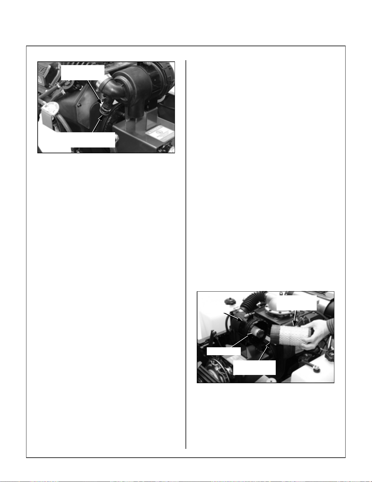
Maintenance Instructions CLEANING
5. Without removing, visually inspect the condition
Air Restriction
Gauge
of the safety filter for damage or holes. The
safety filter should only be removed for yearly
replacement (or when dirty or damaged).
6. Check the condition and resilience of the radial
sealing surface (inside of the open end) of the
filter. Replace the filter if any cracks, tears, or
other damage to the sealing surface are noted.
Push Button to Reset
Indicator After Service
Air Restriction Gauge Location
Inspect the paper element after every 100 hours of
service and replace the element and safety filter
yearly (or when dirty or damaged). More frequent
replacement may be required when operating in
extremely dusty conditions as indicated by the air
restric tion gauge . Service the air cleaner as follows:
1. Lift Mono Latch Twist Lock™ and twist the
OptiAir™ cover to the left into the "open"
position to remove the air cleaner cover. Wash
the cover and dust ejection valve. Check that
these components are in good condition. The
dust ejection valve is subject to wear and
deterioration and should be replaced yearly or
when damaged. The lips of the valve should
close and fit together; any cracks, deformation,
or wear in the valve is cause for replacement.
2. Remove the filter element by pulling it out of the
canister. There will be some initial resistance as
the filter seal breaks loose and slides off of the
outlet tube. Gently move the end of the filter up
and down and side to side or twist to loosen the
seal. Use gentle action to minimize the amo unt
of dust dislodged as the filter is removed.
3. Replace the filter element.
NOTE: Washing the element in water or clean-
ing solution is not recommended. Do not try to
clean the element with compressed air.
4. Use a bright light inside the element to inspect
for damage. Check the element very carefully
for pin holes or other damage that will allow
dirt to leak through the paper media. Replace
element if necessary.
7. Use a clean, damp cloth and wipe the interior of
the air cleaner canister clean. Use special care
to clean both the inside and outside surfaces
of the outlet tube.
IMPORTANT: Any du st le ft on the ins ide of the
outlet tube will go into the engine and cause wear.
8. Check the outside surface of the outlet tube for
smoothness and cleanness (this is the sealing
surface).
9. Insert and seat the safety filter and OptiAir™ element carefully into the canister , applying pressure at the outer rim of the filter; not at the
flexible center. Make sure the filter element is
completely in place before installing the cover.
NOTE: DO NOT use petroleum based lubricants on the sealing surfaces of the filter; u se talcum powder or dry silicone lubricants if required
for filter installation.
OptiAir™
Canister
Safety Filter
Radial Sealing
Surface
Air Filter Element Replacement
Filter Element
42
Page 47

Maintenance Instructions CLEANING
3
DOWN
2
10. Install the cover with the word “DOWN” properly
oriented to the bottom of the canister . Twist the
OptiAir™ cover to the right and put into the
"closed" position.
Mono Latch
Twist Lock™
Rotating Engine Screen
DOWN
Orient to Bottom
of Canister
Dust Ejection
Valve
Proper Orientation of Air Cleaner Cover
1 1. Check the air intake hose for cuts, nicks, cracks,
etc., and the hose clamps for tightness.
12. Reset the air re striction indicator (press butt on
on the end of indicator).
Engine Cooling System
Air Intake System
To prevent engine overheating and possible engine
damage, clean grass clipping s, chaff, and dirt from
the rotating engine air intake screen after every 8
hours of operation. In certain mowing conditions
(dry grass, leaves, tree “cotton”, etc.), it may be necessary to check and clean the screen several times
each day to prevent engine overheating.
Keep Engine Screen Clean
Cylinder Head Cooling Fins
It is essential for performance and longevity of the
air-cooled engine to keep the cylinder head cooling
fins clean and free of obstruction. After every 8
hours of operation, check the performance of the
cooling system by starting the engine, holding a
hand adjacent to the cylinder head, and feeling the
cooling airflow . If there is little or no airflow, clean the
cooling fins as described on the next page.
DANGER
Make sure to keep hands clear of exhaust
pipe, muffler, and moving parts when
checking airflow.
Check Airflow
with Hand
CAUTION
Operating the engine with a blocked air
intake screen, dirty or plugged cooling
fins, and/or cooling shrouds removed will
cause engine damage from overheating.
Cooling System Airflow
43
Page 48

Maintenance Instructions CLEANING
Every 100 hours, inspect and clean the cooling fins
(more often when operating in extremely dusty, dirty
conditions). Remove the two ( 2) co oling fin acces s
panels in the engine shroud and clean the cooling
fins and external surfaces using compressed air.
Make sure to reinstall the access panels before op erating the engine.
Engine Cooling
Fin Access Panels
Kohler Engine
Shroud
Engine Air
Intake Screen
Grass Buildup in Mower Housing
DANGER
Before raising or removing the mower
deck for cleaning, stop the engine, remove
the ignition key , an d disconnect the sp ark
plug wires.
1. Release hood latch assembly (2) and remove
footrest.
2. Rotate locking arms upward on each side of the
carrier frame to release carrier frame for tilting
action.
Engine Air Intake Screen
and Cooling Fin Access Panels
Locking Arm Rotation
3. Install tilt bar into front of deck.
44
Tilt Bar Installed
Page 49

Maintenance Instructions CLEANING
4. Using the tilt bar, raise deck to the TILT-UP posi-
tion and insert the deck hook into the tilt- up latch
on the tractor body.
Tilt-Up Latch
Tilt-Up Hook
on Deck
Deck Secured in Tilt-Up Position
5. Clean grass buildup underneath the deck using
a pressure washer (and scraper if required).
8. Reinstall footrest by inserting locking fingers
under deck plate and reattaching hood latch
assembly.
Footrest
Locking
Finger
Deck Plate
Hood Latch
Assembly
Footrest Installation
CAUTION
Do not operate machine with deck locking
arms disengaged.
NOTE: If the buildup is severe, it may be easier
to clean the deck by removing the deck assembly
from the tractor and standing the desk assembly
on its “nose”.
NOTE: While some degree of material buildup
in the mower deck housing can be tolerated, a
point is finally reached where cutting quality
deteriorates and clogging begins to occur
because of too much buildup on the baf fling and
housing.
DANGER
Do not operate the mower with deck in tiltup position. Do not move the tractor with
the deck in the tilt-up position.
6. Lower the deck to the normal operating position
and rotate locking arms downward.
7. Remove tilt bar and store on carrier frame.
45
Page 50

Maintenance Instructions CLEANING
Transaxle Cooling Fins
Keeping the cooling fins on the transaxles clean and
free of obstruction is essential to avoid
overheating the transmission fluid and shortening
transmission life. The cooling fins should be
checked every 100 hours; and cleaned if
necessary.
To clean the fins, use compressed air and/or a pres sure washer. The cooling fins extend all the way
around the housing -- the fins underneath need to be
clean as well as the more visible fins above. Also,
pay close attention to the area under the drive pulley .
IMPORTANT: In case an oil leak develops on the
input shaft, the cooling fan blowing dusty air and oil
on the transmission will quickly pack the cooling fins
with oily dirt. If this condition occurs, contact your
dealer immediately to avoid overheating and damaging the transaxle.
An additional procedure in maintaining transaxle
cooling is to inspect the cooling fans. Replace the
fan(s) if blades are missing or damaged.
Cooling
Fans
Transaxle Cooling Fans
46
Page 51

Maintenance Instructions CHECKING/SERVICING
CHECKING/SERVICING
DANGER
To prevent accidental starting of the engine when servicing or adjusting the machine, remove the key from the ignition
switch and disconnect the spark plug
wires.
Security of Air Filtration Components
NOTE: The following inspection is only an external
inspection and should be done without “disturbing” the filtration components.
On a daily basis, visually inspect the external condition of the complete air cleaner system. The
following items should be inspected:
1. Check the Cummins/Fleetguard OptiAir™ air
cleaner canister for damage. Make sure the
cover is in place and the cover latch is secure do not run the engine without the air cleaner
cover in place and secure.
Charging the Battery
DANGER
BATTERIES PRODUCE EXPLOSIVE
GASES
• Charge the battery in a well-ventilated
area, so that gases produced while charging can dissipate.
• Keep sparks, flames, and smoking ma-
terials away from the battery at all times.
• Make sure the batt ery cap vents are open
(check manifold vent on each cap).
• Make sure the battery charger is un-
plugged before connecting or disconnecting cables to the battery.
Check the battery charge by measuring the specific
gravity of electrolyte; if specific gravity is less than
1.225, the battery will need to be charged as follows:
2. Inspect the air intake hose for cracks, nicks,
cuts, etc., and check the hose clamps for
tightness.
3. Check to ma ke sure the air flow indicator is in
place and tight.
Battery
NOTE: For initial battery service during setup, refer
to Battery Service in Assembly Instructions.
IMPORTANT: Make sure battery is securely
mounted in the frame. A loose battery may cause
damage to the case resulting in acid leakage and
severe damage to the machine. A hazard may be
created by damage to critical working parts and
safety systems.
Cleaning the Terminals
If battery terminals are corroded, remove battery
from the mower. Using a wire brush, remove corrosion with a solution of one part baking soda and
four part s water. Rinse with clean water . Coat the
terminals with petroleum jelly or termin al protector
spray to retard further corrosion.
• Charge the battery at 15 amps for 10 minutes.
DO NOT exceed 20 amps maximum recommended
charging rate. Charge until specific gravity is at
least 1.250. Total charging time should not exceed
one (1) hour.
Tire Pressure
Inflate tires to pressures shown below:
Deck Caster Wheel = 20 PSI (137 kPa)
Drive = 15 PSI (103 kPa)
Rear = 20 PSI (137 kPa)
Wheel Nuts Torque
Check every 100 hours the eight (8) Drive Tire
mounting nuts. They should each be torqued to
75-85 ft-lbs. (101.7-115.2 N
Sharpen Mower Blades Check mower blade(s) for straightness, sharp-
ness, condition of th e cutting edge, and balance
every 10 hours of operation (or more often when
mowing abrasive type grass or operating on sandy
soils). Replace blades if worn, bent, cracked, or
otherwise damaged (refer to REPLACING/
REPAIRING the Mower Blades in this section).
Use th e following procedure to check and sharpen
blades:
·m).
47
Page 52

Maintenance Instructions CHECKING/SERVICING
NOTE: Keep blades sharp - cutting with dull
blades not only yields a poor mowing job but slows
the cutting speed of the mower and causes extra
wear on the engine and blade drive by pulling hard.
1. Stop the engine, remove ignition key, and disconnect the spark plug wires before raising the
mower deck to service blades.
2. Raise the deck and secure it in the tilt-up position (refer to Deck Secured in Tilt-Up Position
photo in CLEANING of Grass Buildup in
Mower Housing in this section).
DANGER
ALWAYS wear eye protection and glo ves
when sharpening a blade.
6. Check blade balance by positioning the blade
horizontally on a blade balance r or use a nail or
shaft through the center hole. If either end of the
blade rotates downward, grind (remove) metal
on that end until the blade will balance. The
blade is properly balanced when neither end
drops. Balance of a blade is generally maintained by removing an equal amount of material
from each end of the blade when sharpening.
CAUTION
NEVER operate cutter blades with the
deck in the raised position.
NOTE: PTO shaft must be disconnected
before checking blades for straightness.
3. Chec k the blades for straightness by ma rking
the blade tip position inside the deck housing,
and then rotating the opposite end of the blade
to the same position and comparing. If the difference in blade tip track is more than 1/8 in.
(3 mm), the blade is bent and should be replaced.
WARNING
DO NOT try to straighten a blade that is
bent. NEVER weld a broken or cracked
blade. ALWAYS replace with a n e w b la d e
to assure safety.
4. If the blade cutting edge is dull or nicked, it
should be sharpened. Remove blades for
sharpening by grasping the end of the blade
using a rag or a thick, padded glove, while loosening and removing the bolt and washer that
mounts the blade.
5. Grind cutting edge at the same bevel as the
original. Sharpen only the top of the cutting
edge to maintain sharpness.
NOTE: Blades can be sharpened with an
electric blade sharpener, conventional electric
grinder, or a hand file.
Sharpen at Original
30° Angle
30°
Do Not Grind or
Sharpen on Underside
Mower Blade Profile For Sharpening
Blade Balancer
Blade Balanced on Magnetic
Wall-Mounted Balancer
7. Mount the blade with wing tips pointing up into
the housing. Reinstall the blade, washer, and
bolt. Tighten the bolt to 64 ft-lb (86.8 N
Intersection
Wear Area
Wing Tip
·m).
48
Page 53

Maintenance Instructions
CHECKING/SERVICING/
REPLACING/REPAIRING
Drive Belts
Raise the body and inspect the condition of the four
(4) drive belts after every 25 hours of operation -engine/PTO drive and g round drive. If the belts show
signs of cracking or deteriorating, the belts
should be replaced. Refer to REPLACING/REP AIR-
ING the Drive Belts in this section.
Spark Plugs
Every 200 hours, remove the spark plugs, inspect,
clean, and reset the gap (or replace with a new
plug). Clean spark plug with a wire brush. If the
electrodes are burned short or pitted, replace the
plug (refer to Specifications for the proper type of
replacement plug). Check the spark plug gap with a
wire-type feeler gauge and set the gap to 0.030 in.
(0.76 mm). Reinstall and tighten to 18 ft-lb
(24.4 N
Fuel Lines and Clamps
Every year, inspect the fuel lines from the tanks to
engine for deterioration or damage. Also, inspec t the
fuel line clamps for tightness. Good preventive
maintenance calls for complete replacement of fuel
lines and clamps every two (2) years.
Blade Brake Action
·m). Both spark plugs should be replaced yearly .
REPLACING/REPAIRING
DANGER
To prevent accidental starting of the
engine when replacing parts or repairing
the machine, remove the key from the
ignition switch and discon nect the spark
plug wires.
IMPORTANT: ALWAYS use genuine factory re-
placement parts. Substitute parts CAN result in
product malfunction and possible injury to the operator and/or others.
Drive Belts There are four (4) individual belt s on the machine:
• Engine/PTO Belt [Matched Set (3)]
• Ground Drive Belt
The belts may be removed and replaced using the
procedures described on the following pages.
Ground
Drive Belt
Clutch
(Ref)
WARNING
It is important to check and maint ain blade
brake action for safe operation of the machine.
Check the function of the cutter blade brake by
engaging the blade clutch (PTO), operating the
engine at full throttle, then disengaging the clutch
and measuring how quickly the blades stop. Watch
the rotation of the blade drive shaft as a visual indication that movement has stopped. If the brake is
working properly, all rotation will stop five (5)
seconds after disengagement of the clutch. If the
brake system malfunctions -- blades do not stop in
five (5) seconds -- repair the brake before opera ting
the mower.
Engine/PTO Belt
(Matched Set)
Belt Locations (Engine Hidden for Clarity)
49
Page 54
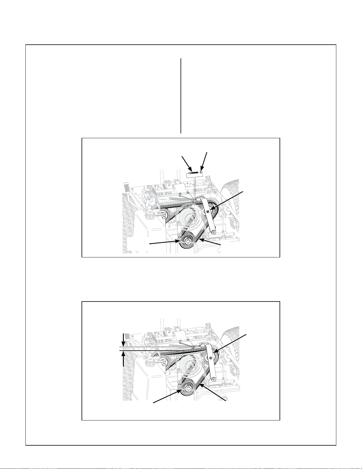
Maintenance Instructions REPLACING/REPAIRING
Engine/PTO Belt
1. To remove the engine/PTO belt:
a. Loosen and remove idler tension bolt and
jam nut.
b. Relax belt by depressing idler arm.
c. Roll the belts off the pulley and remove the
belts.
Idler Tension
PTO
Pulley
Engine/PTO Belt (Disengaged)
(Engine Hidden for Clarity)
2. Rever se the removal procedure to re place the
engine belts.
Bolt
Jam Nut
Idler Arm
Engine/PTO
Belts
50
1/2 in. deflection
PTO
Pulley
Idler Arm
Engine/PTO
Belts
Engine/PTO Belt (Engaged)
(Engine Hidden for Clarity)
Page 55

Maintenance Instructions REPLACING/REPAIRING
Ground Drive Belt
1. To remove the ground drive belt:
a. Raise the spring-loaded idler to relax belt.
LH Transaxle
Idler Pulley
Raise Idler Pulley to
Ground Drive
Belt
Relax Belt
b. Slide belt off pulleys, then release the
idler.
Tension
Spring
Hydro Idler
RH Transaxle
Drive Pulley
Arm
Ground Drive Belt Assembly (Disengaged)
2. Reverse the procedure to install the ground
drive belt.
Ground Drive
Belt
LH Transaxle
Idler Pulley
RH Transaxle
Drive Pulley
Hydro Idler Arm
Ground Drive Belt Assembly (Engaged)
51
Page 56
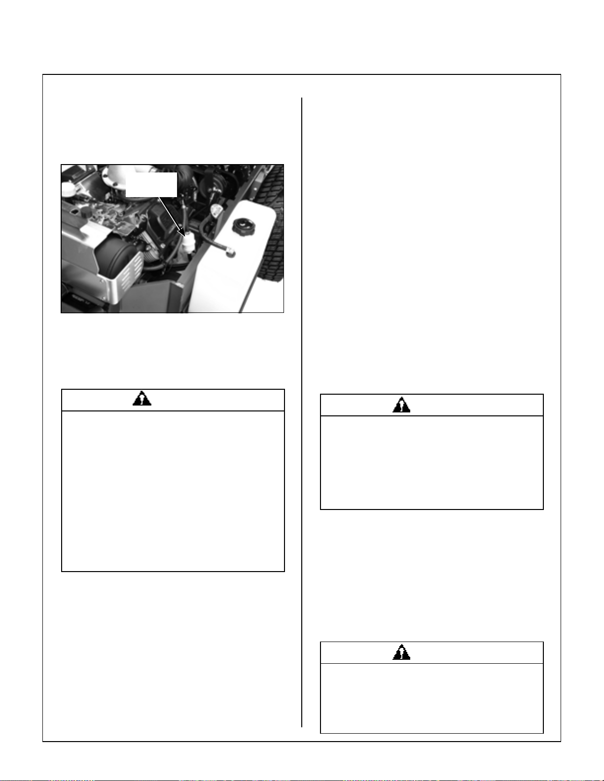
Maintenance Instructions REPLACING/REPAIRING
Fuel Filter
Model MBSSD is equipped with in-line fuel filters.
Visually inspect the filter periodically , and replace the
filter yearly.
In-Line
Fuel Filter
Fuel Filter Location
IMPORTANT: Replace the fuel filter only in a clean
area where the fuel line and connections will not be
contaminated by any dust and dirt.
Mower Blades
Mower blades are removed and remounted as described in the Sharpen Mower Blades instructions
(refer to CHECKING/SERVICING to Sharpen Mow-
er Blades in this section). During the course of
sharpening and inspecting mower blades, if there are
any of the following conditions of wear or damage, blades should be replaced for reasons of safe-
ty and performance of the machine:
• An excessive amount of the flat section of the
blade has been ground away (removed) when the
blade is sharpened. Replace the blade when less
than a 3/4 in. (19 mm) flat section remains at the
blade tip.
• Examine ends of the blade carefully , especially the
intersection where the flat section of the blade turns
up to form the “wing tip” (refer to Mower Blade Pro-
file For Sharpening illustration in Sharpen Mower
Blades instructions). Since sand and abrasive ma-
terial can wear metal away in this area, the blade
should be replaced when metal thickness has
worn to 1/16 in. (1.6 mm) or less.
DANGER
Gasoline is extremely flammable and can
be highly explosive. To minimize danger:
• Use only an approved fuel container for
gasoline.
• DO NOT allow open flames or sparks
near the machine while performing maintenance or refueling; DO NOT smoke
while working with fuel.
• Wipe up spilled gasoline immediately
and completely.
1. Expand and slide clamps on either side of the
filter away from filter and pull fuel lines off filter.
2. Replace filter.
DANGER
When blades are operated over sandy soil,
and if blades are allowed to wear, a “slot”
may be worn into the wing tip of blade.
Eventually a piece of the blade may break
off creating a serious potential for injury or
damage.
• Check the blades for straightness by marking
blade tip position inside the deck housing and then rotating the opposite end of the blad e to the same position and comparing. If the difference in blade tip
track is more than 1/8 in. (3 mm), the blade is bent
and should be replaced.
• Inspect the blade surface, especially in formed
areas, for cracks. Replace the blade if any cracks
are found.
WARNING
DO NOT try to straighten a blade that is
bent. NEVER weld a broken or cracked
blade. ALWAYS replace with a new blade
to assure safety.
52
Page 57

Maintenance Instructions
Reinstall the blades following procedure from Sharpen Mower Blades instructions. If blades are re-
placed, always use Walker original equipment
blades to ensure safety and optimum per formance.
The quality and performance of replacement blades
offered by other manufacturers cannot be guar-
anteed, they could be dangerous.
CAUTION
ALW A YS use genuine factory replacement
parts. Substitute parts CAN resu lt in product malfunction and possible injury to the
operator.
REPLACING/REPAIRING/
ADJUSTMENTS
Levers should sit
parallel to each other
ADJUSTMENTS
Transm ission Control
IMPORTANT: The proper adjustment of the tran-
saxle control stops is essential for efficient operation
and life of the transaxle. These stops are properly adjusted at the factory and should only require readjustment if the transaxle or related control linkage is
removed or changed.
NOTE: It would not be unusual for a new machine,
after initial 5 or 10 hours of operation, to begin to not
travel straight (this is due to the break-in of the transaxles).
Steering Lever Position Adjustment - Step 1
NOTE: For proper operation, the steering levers
should be adjusted to sit evenly using the following
procedure.
1. Examine the steer ing levers to make sure th ey
are parallel front to back in relation to one another. If they are not equal, adjust accordingly.
(The handles may or may not be even at this
point.)
NOTE: The LH steering lever is non-adjustable.
This procedure will require adjustment of the RH
lever to make it even with the LH lever.
Lever Alignment
2. Adjust the position of the RH lever by turning the
stop bolt in the Speed Control Actuator in or out.
Turning the stop bolt in will make the RH lever
move back, and turning it out will make it move
forward. Tighten the locknut.
Stop
Bolt
Stop Bolt Location
53
Page 58

Maintenance Instructions ADJUSTMENTS
Steering Handles Adjustment - Step 2
1. An adjustment range of approximately 3 in.
(76.2 mm) is available on the steering handles the handles can be adjusted forward or aft
depending on the arm length of the operator.
The handles can be adjusted by loosening the
locknut at the pivot point and the locknut
holding the handle in position in the adjustment
slide. Adjust the handles into the most
comfortable position and tighten both locknuts.
Locknut
(Position)
Adjustment
Slide
Locknut
(Pivot Point)
Steering Adjustment
4 in.
(101.6 mm)
Steering Lever Adjustment
Neutral Position Adjustment - Step 3
1. With the Forward Speed Control (FSC) in neutral, the lever should be straig ht up. Adjust by
loosening the jam nuts on the FSC Rod and turn
the rod to attain the straight up position. T ighten
the jam nuts.
2. The initial adjustment for neutral is to loosen the
jam nuts on each end of th e Hydro-Gear Control
Rods and turn the rods to achieve a measurement of 4 in. (101.6 mm) between the jam nuts.
Be sure to tighten jam nuts before making the
measurement.
Actuator Rod Length Adjustment
3. Block the tractor up so the drive tires are off the
ground.
54
FSC Position
4. With the FSC in neutral, start the engine. (Operate first at idle and then normal operating
speed) and check for movement of drive wheels.
Page 59

Maintenance Instructions ADJUSTMENTS
NOTE: If the engine will not start, check and adjust the neutral safety switch (refer to Neutral
Switch Adjustment - Step 6).
5. With the FSC in the neutral position and the engine running, the wheels should not move. If a
drive tire is moving, the Control Rod on that side
is out of adjustment. Adjust that side to achieve
neutral. Now both transaxles are in the neutral
window.
Control Rods
Neutral Travel End
Neutral Travel End
(Shown with Parts Removed for Clarity)
Straight Tracking Adjustment - Step 5
1. Sit in the seat, start the engine, set throttle at full
speed, and with the FSC in the NEUTRAL-P ARK
position check for movement of either drive
wheel (if either wheel moves backward or forward, refer to the Neutral Position Adjustment -
Step 3 and readjust).
Neutral Window
(Front Body Hidden for Clarity)
6. One at a time adjust the left and right Control
Rods to find the center of the neu tral window.
Shorten the rods until the drive tire turns forward
then lengthen it until the drive tire turns in reverse
(approximately 1 turn). Position the rods halfway
between forward and reverse. Tighten the jam
nuts.
7. Lower drive tires onto ground.
Full Forward Speed Adjustment - Step 4
1. Move the FSC to the full forward speed position.
2. Raise the body. The set screws in the left and
right Transmission Control Arms should not be
contacting the locating stud in the transaxle. If
they are, back the set screws out until they do not
touch.
2. Check for straight ground tracking on a level
surface (with hands off the steering levers). Set
the FSC at several different speeds and observe
if the mower moves in a straight line (use cement
joint or other line on ground for reference).
3. If travel is not straight, shorten the control rod of
the slow side (adjust in 1/8 turn increments) to
match the faster side while maintaining the neutral position. If straight tracking and neutral can
not be achieved, turn the control rod back to
where neutral can be achieved.
4. Lengthen the control rod of the faster side (adjust
in 1/8 turn increments) to match the slower side
while maintaining the neutral position.
5. If the forward travel is straight throughout the
speed range, except at maximum speed - place
the FSC in full forward, turn the set screw in the
Transmission Contro l Arm, o f the fa ster side, i n
until it contacts the hydro stud. (T ur ning the set
screw in slows the wheel.) Turn the set screw in
an additional 1/8 turn. Recheck for equal full forward speed. Adjust this set screw until equal full
forward speed is achieved. Tighten the ja m nut.
55
Page 60

Maintenance Instructions ADJUSTMENTS
Forward Speed Control Friction Adjustment - S tep 7
Neutral Travel End Adjust
FSC Switch - Neutral Adjustment - Step 6
1. Place the FSC in neutral position. Loosen
mounting screws and adjust switch up or down
accordingly.
FSC Switch
FSC Switch Location
Switch Closed
in Neutral
FSC Switch
Actuator Arm
FSC Position With Levers
1. Place the FSC in the full forward position and
pull both steering levers back; the FSC lever
should not move. If the FSC lever moves back
the friction needs to be increased.
2. With the steering levers held back, move the
FSC lever back from the forward position. With
a proper amount of friction adjusted, the FSC lever should move back with a slight amount of resistance (friction). If the FSC lever movement is
"stiff", the friction needs to be decreased.
3. The FSC friction is increased or decreased by
tightening or loosening the friction adjustment
nut. Loosen or tighten the nut and check the
control function until the conditions of both steps
1 and 2 are met.
PTO Belt Tension
PTO belt tension can be adjusted by lengthening or
shortening the position of the adjustment bolt on the
idler adjuster (above idler pulley). Optimum adjustment will result in a 1/2 in. (1.27 cm) deflection of
the belt.
1/2 in. (1.27 cm)
deflection
56
Deck Support
Arm (Ref)
Loosen Screws
FSC Switch Adjustment
(Side View Through Chassis)
PTO Belt Tension Adjustment
Page 61

Maintenance Instructions
ADJUSTMENTS/
ELECTRICAL SYSTEM
PTO Clutch
WARNING
It is important to check and maintain
blade brake action for safe operation of
the machine.
The declutched or disengaged position of the PTO
clutch is adjustable and is set to completely release
spring tension on the mechanical clutch. The
spring in the linkage that engages the clutch shou ld
not have any tension on it when the clutch is
disengaged. Adjust the PTO clutch engagement
adjustment bolt up or down to allow minimal free
movement in the disengaged position. If this can
not be achieved, the clutch rod will need to be
adjusted.
Spring Hangs
Freely When
Disengaged
NOTE: When making any of the PTO clutch
adjustments, it is important that the overall length
from the top of the clutch engagement spring to the
lower mounting of the clutch actuator link be 5-1/4 in.
(13.3 cm) when engaged.
Clutch Rod
The clutch rod and ball joints are factory adjuste d to
10-1/4 in. (26.0 cm) overall length. Increasing the
length will increase the free movement of the spring
on the clutch engagement arm. Decreasing the
length will increase the amount of spring stretch in the
engaged position. (Refer to PTO Clutch Adjust-
ment - Engaged illustration.)
PTO Clutch
Lever
(Disengaged)
Adjustment Bolt
and Jam Nut
PTO Clutch Adjustment - Disengaged
PTO Clutch
Lever
(Engaged)
5-1/4 in.
(13.3 cm)
10-1/4 in.
(26.0 cm)
Clutch Rod Adjustment
ELECTRICAL SYSTEM
For troubleshooting, refer to the WIRING SCHE-
MATIC.
IMPORTANT: Disconnect both battery cables be-
fore unplugging any wiring connectors or making repairs on the electrical system.
PTO Clutch Adjustment - Engaged
57
Page 62

TRACTOR AND DECK DECALS
I T E M PA R T D E S C R I P T I O N L O C A T I O N N O .
NO. NO. REQ’D SD
Walker Product and Operation Decals
1 2802-2 RH Fender Body, RH near Seat 1
2 2010-4 Fuel Transfer Transfer Mount 1
3 5800-6 Decal, Walker 6-3/4" Rear Body (one on each side) 2
4 2802-1 LH Fender Body, LH near Seat 1
5 9804 Axle Lockout Chassis 2
6 5856 Made in USA Body 1
7 5803 Walker Manufacturing Logo Body 1
8 2748 Cutting Height Adjustment Carrier Frame 1
9 5800-5 Decal, Walker 8" Deck Footrest, Front 1
Danger Decals Warning Decals Caution Decals
10 5805 Caution, Engine Exhaust Rear Body 1
11 6810 Danger, Engine Exhaust Engine, LH Side 1
12 2107-4 Decal, Belt Routing Rear Body, Underside 1
13 4107-1 Danger, Rotating Components Air Cleaner Bracket 1
14 5808 Danger, Rotating Blades Deck Housing (one on each end) 2
15 8647 Danger, Tilt-Up Carrier Frame 1
16 8653-1 Transport Warning Deck Housing 1
17 8653 Caution, Pivot Joint Carrier Frame 2
18 2749 Decal, Drive Belt Routing Deck Housing 1
19 5848 Danger, Side Discharge Shield Side Discharge Shield 1
Maintenance Decals
20 2105-8 RH Decal, 27 HP Rear Body, RH Side 1
21 2105-9 LH Decal, 27 HP Rear Body, LH Side 1
22 5855 Important, Engine Cooling Engine 1
23 2807-1 Decal, Oil Pressure/Head Temp. Body 1
24 6875 PTO Alignment Arrow Universal Joint Tube Assembly 1
25 8746 Universal Joint Lube Mount Bracket / PTO Guard 1
26 2732 Decal (60") Deck Housing, Front 1
Option Decals (applied only to units with corresponding Options installed)
27 5877 Lights, On-Off Body 1
NOTE: All parts requiring decals are shipped with decals applied.
58
Use only genuine Walker® replacement parts. Effective Date 03-31-08
Page 63

TRACTOR AND DECK DECALS
D
R
I
V
E
BE
LT
W
A
L
KE
R
P
/
N
27
3
1
CAR
L
ISLE
P/N
R
3
VX
1
2
50
2
BE
L
T
T
WI
S
T
DRI
V
E
P
UL
L
EY
W
A
L
KER
P
/
N
224
0
1
BEL
T
T
WI
S
T
2
7
4
9
BL
A
D
E
PU
L
L
EY
W
A
L
KE
R
P/N
224
0
3
10
20
2
21
1
27
19
8
23
17
5
7
13
5
6
22
12
11
3
4
14
25
DRIVE BELT
WALKER P/N 2731
CARLISLE P/N R3VX1250-2
BELT ROUTING
BELT TWIST
DRIVE PULLEY
WALKER P/N 2240-1
9
BELT TWIST
18
24
17
BLADE PULLEY
WALKER P/N 2240
2749
16
15
26
14
Effective Date 03-31-08 Use only genuine Walker® replacement parts.
59
Page 64

BODY / CHASSIS ASSEMBLY
ITEM PART DESCRIPTION NO.
NO. NO. REQ’D
Body & Seat Assembly
1 2103-1 Seat 1
2 2105-1 Rear Body (Includes Item # 3) 1
3 2190-1 Insulation Foam Pad 1
4 5845 Rubber Bumper (1.50 x 1.25) 2
5 5146 10mm Ball Stud 2
6 2145 Gas Spring 1
7 5180 Edge Molding, Lever Opening 2
8 2100-3 Front Body Doubler 1
9 2504-4 Hinge (22.5) 1
10 2100-1 Front Body 1
11 5989-5 Dome Plug (7/16) 1
12 2383 Body Latch Hook 1
13 7854 Plastic Tip, Red 1
14 7222 Extension Spring (1/4 x 3) 1
15 5989-4 Dome Plug (3/8) 2
16 5989-3 Dome Plug (5/16) 2
Chassis Assembly
17 2390-1 Battery Pan 1
18 2046-1 Gas Tank Mount, LH 1
19 2300-3 Chassis Frame 1
20 2046 Gas Tank Mount 1
Tail Wheel Assembly
21 5830 Grease Fitting 4
22 2201-2 Fiberglide Thrust Washer 2
23 2201-3 Fiberglide Bearing (1-5/8) 2
24 2300-6 Tail Wheel Pivot (Includes Items # 21 & 25)1
25 5830-3 Grease Fitting (45 Deg.) 1
26 2201-4 Washer (2-1/4 x 7/16 x 1/4 Thk) 1
27 8769-8 Dust Cap, Deck Caster 2
28 8769-6 Bearing Cone (1" ID) 4
29 8769-5 Bearing Cup (2 x 1-5/8) 4
30 8769-7 Seal 2
31 2770 Caster Wheel Fork 2
32 8039 Nut, Tail Wheel Axle 2
33 8038-1 Spacer, Tail Wheel Axle 2
(.750 x ID x 1.125 OD)
34 8768-2 Seal, Reverse Lip 2
35 8037 Bearing Cone (3/4 ID) 4
36 8035 Tail Wheel & Tire (13 x 5.00-6) 2
(W/Bearing Race)
37 8037-1 Seal, Outer (1-3/4 x 1-1/8) 2
38 7038 Tail Wheel Axle (3/4 x 5-9/16) 2
Deck Support Arm & Hitch Assemblies
39 2300-9 Deck Arm Support Mount 1
40 6840-1 Support Arm Bushing (2-1/16) 2
41 2775 Lynch Pin (5/16 x 1-1/4) 2
42 2431 Deck Support Arm, LH 1
(Includes Item # 21)
43 2430 Deck Support Arm, RH 1
(Includes Item # 21)
ITEM PART DESCRIPTION NO.
NO. NO. REQ’D
Deck Arm Adapter Kit
44 2431-1 Deck Arm Adapter, LH 1
45 5775-2 Hitch Pin (#6) 2
46 2430-1 Deck Arm Adapter, RH 1
47 2744-2 Counter Weight Spring Extension 1
48 2744-4 1/4" Quick Link 1
49 2744-5 Chain 1
Tilt-Up Latch Assembly
50 5847 Plastic Tip 1
51 5744-20 Spring Arm, Tilt-Up Latch 1
52 5744-10 Spring Pivot Bushing 1
53 5744-15 Compression Spring (3/8 x 5/8) 1
54 5744-13 Mount Angle, LH 1
55 5744-12 Hook, Tilt-Up Latch 1
56 5744-14 Mount Angle, RH 1
Fasteners
F002 10-24 Keps Nut 5
F004 1/4-20 Keps Nut 11
F005 1/4-20 ESNA Nut 2
F009 5/16-18 Whiz Locknut 16
F013 3/8-16 Whiz Locknut 2
F020 5/16-18 ESNA Nut 1
F025 10-24 x 3/8 PPHMS 5
F029 1/4-20 x 1/2 Hex Bolt 2
F034 5/16-18 x 3/4 Hex Bolt 8
F093 5/16-18 x 1 Hex Bolt 1
F151 3/8-16 x 7/8 Hex Bolt 2
F183 .312 x .700 x .074 Washer 4
F205 5/16-18 x 1/4 Set Screw (Knurl Point) 2
F218 7/16 Split Lock Washer 5
F219 7/16-14 x 1-1/4 Hex Bolt 5
F236 1/4-20 x 1-3/4 Hex Bolt 2
F246 1/4-20 x 1/2 PTHMS 4
F256 7/16 SAE Washer 1
F341 Coil Roll Pin (7/64 x 9/16) 1
F342 5/16 Conical Washer 2
F344 3/4-16 Slotted Hex Nut 2
F347 3/4 SAE Washer 2
F348 1/8 x 1-1/2 Cotter Pin 2
F430 7/16-20 ESNA Nut 2
F442 1/4-20 x 5/8 PTHMS 5
F446 7/16-20 x 3-1/2 Grd 8 Bolt 2
*
**
* Complete Deck Arm Adapter Kit available by ordering
kit 2430-10. This kit allows the use of all Side Discharge
Decks with the MBSSD Tractor.
** Complete Tilt-Up Latch Assembly Kit available by ordering
kit # 5747.
60
Use only genuine Walker® replacement parts. Effective Date 03-31-08
Page 65

BODY / CHASSIS ASSEMBLY
1
2
F020
56
F004
48
F029
F342
55
49
F342
8
50
51
F341
F029
52
53
11
10
9
54
F236
F093
F004
12
13
14
7
47
F034
20
F442
F246
F005
F009
F004
F005
15
16
F002
F025
25
24
21
17
22
F013
22
23
23
21
F151
31
F219
F218
F205
F219
26
F256
16
15
F236
F183
F009
F009
5
5
6
F009
F009
4
F009
F218
3
27
F344
F348
F347
28
29
29
28
30
F218
F219
19
F034
F446
41
21
45
40
43
46
45
F009
F430
F009
39
41
42
F430
21
40
44
F034
F446
18
F034
32
33
34
35
Effective Date 03-31-08 Use only genuine Walker® replacement parts.
36
35
37
38
61
Page 66

MAIN COMPONENT POWER TRANSMISSION
ITEM PART DESCRIPTION NO.
NO. NO. REQ’D
PTO Drive Assembly
1 4850 Handle Grip 1
2 2358 Clutch Lever (Includes Item # 1) 1
3 5830-4 Grease Fitting (90 Deg.) 1
4 5214-2 Ball Joint (5/16-24) (Nylon Lined) 2
5 4358-1 Clutch Rod 1
6 5229 Extension Spring (1/2 x 2-1/4) 1
7 2358-5 Clutch Actuator 1
8 5103-2 Pivot Bushing (5/16 ID) 2
9 2358-6 5/16-18 x 1-3/4 Stud 2
10 2349-2 Bearing Mount Plate 1
11 2349-3 Switch Pivot Mount 1
12 7407 Clevis Pin (3/16 x 1/2) 2
13 2358-4 Clutch Actuator Link 2
14 4358-5 Clutch Linkage Spring 1
15 2236 PTO Pulley 1
(Includes Items # F075, F114 & F435)
16 5268 Bearing W/Collar (3/4) 2
17 2274-6 PTO Drive Shaft (1") 1
2274-5 PTO Drive Shaft Assembly
18 7275-9 Quick Coupler Installation Tool **
19 7275-16 Universal Joint Tube Assembly / Spline 1
20 2274-7 PTO Bearing Housing 1
21 4325-3 Clutch Stop 1
22 2325-1 Clutch Retainer 1
23 2325-4 Idler Adjustment 1
24 2265 Bearing (20mm) 4
25 2406-7 Pivot Shaft Spacer 1
26 2236-1 Idler Pulley (4.5/AAA) 2
27 7201-7 Inner Race (2-5/8) 1
28 7201-3 DU Bearing 2
29 2230 Engine PTO Belt/Set (3) 1
30 2236-4 Idler Pulley Shaft 1
31 2325-3 Idler Adjuster 1
32 2325-2 Tensioner Bolt 1
33 5830-3 Grease Fitting (45 Deg.) 1
34 2325 Idler Arm (Includes Item # 33) 1
35 5841 Retainer Washer (3/8 x 1-1/4) 1
36 2410 Mechanical Clutch 1
*
ITEM PART DESCRIPTION NO.
NO. NO. REQ’D
Fasteners
F004 1/4-20 Keps Nut 5
F008 5/16-24 Keps Nut 2
F009 5/16-18 Whiz Locknut 12
F012 3/8-16 Keps Nut 1
F013 3/8-16 Whiz Locknut 3
F020 5/16-18 ESNA Nut 1
F024 5/16-24 Jam Nut 2
F029 1/4-20 x 1/2 Hex Bolt 1
F031 1/4-20 x 5/8 Hex Bolt 5
F034 5/16-18 x 3/4 Hex Bolt 5
F046 3/8-16 x 3-1/2 Hex Bolt 1
F091 5/16-18 x 5/8 Hex Bolt 1
F093 5/16-18 x 1 Hex Bolt 4
F114 5/16-18 x 5/8 SQH Set Screw 1
F127 1/16 x 1/2 Cotter Pin 2
F163 5/16-18 x 3/4 SQH Set Screw 1
F168 5/16 Split Lock Washer 1
F170 5/16 x 1 x 7/64 Flat Washer (Zinc Plate) 1
F178 1/4 x 1 Fender Washer 1
F185 1/4 Int. Star Lock Washer/SS 1
F241 .375 x .875 x .10 Washer 2
F336 3/8-16 Jam Nut 1
F388 3/8-16 x 2-1/2 Hex Bolt 1
F435 1/4 x 1/4 x 1-1/4 Key 1
* Service Part Only
** The Quick Coupler Installation Tool is used to assist the
installation of the Quick Coupler Tube and PTO Shaft connection by holding the disconnect ring in the retracted position
when joined to the tractor spline shaft on the PTO Drive
Shaft.
62
Use only genuine Walker® replacement parts. Effective Date 03-31-08
Page 67

MAIN COMPONENT POWER TRANSMISSION
1
F388
F241
2
3
F008
4
F024
7
9
F009
F024
8
F029
F185
F034
F013
5
4
F034
F031
10
11
F004
F009
21
F009
Refer to
Body / Chassis Assembly
F031
F009
F127
F012
36
34
31
F336
F013
32
27
28
F241
24
30
26
29
24
F046
33
35
F034
24
25
F009
14
13
F004
9
F008
6
8
12
F020
12
F178
22
Refer to
Hydrostatic Ground
Drive Assemblies
Refer to
Engine Group
F091
F168
F170
26
24
19
23
F009
F093
20
F009
16
17
16
F163
F114
F435
15
Effective Date 03-31-08 Use only genuine Walker® replacement parts.
18
63
Page 68

ENGINE GROUP
ITEM PART DESCRIPTION NO.
NO. NO. REQ’D
Fuel Tank Assembly
1 8046-9 Fuel Tank, 5.0 Gallon, Gas 2
(Includes Item # 3)
2 5082-2 Fuel Cap Seal 2
3 5082 Fuel Tank Cap 2
(Includes Item # 2)
4 5083-5 Tank Tube Elbow 2
5 5083-1 Bushing, Rubber (Fits 5083) 2
6 5086-7 Hose (3/8 x 6) 2
7 5020-2 Fuel Filter, In Tank 2
8 5879-3 Hose Clamp (1/2) 7
9 5086-10 Hose (1/4 x 9) 1
10 2010-3 Fuel Valve 1
11 2010-2 Fuel Transfer Mount 1
12 NS Kohler Hose
13 5020 Fuel Filter 1
14 5086-11 Hose (1/4 x 12) 1
15 5086-12 Hose (1/4 x 46) 1
16 7833-2 Cable Clamp (1 x 1/4) 2
Engine Assembly
17 NS 27 HP Engine (Kohler)
18 NS Muffler *
19 2104 Body Support 1
20 4845 Rubber Bumper (1.0 x .625) 2
21 NS Kohler Nut
22 2013-4 Shield Side 2
23 2013-3 Muffler Heat Shield 1
Precleaner Assembly
24 7840 Hose Clamp (1-5/16 to 2-1/4) 2
25 2012 Flex Hose (1-3/4 x 2) 1
26 2088-10 Air Cleaner Assembly
(Includes Items # 27-32)
27 5091-11 Air Flow Indicator & Nipple 1
28 2088-1 Air Cleaner Band 1
29 2090-3 Safety Filter Insert 1
30 2090-1 Air Cleaner Cartridge 1
31 2088-2 Air Cleaner Cap 1
32 2090-2 Vacuator Valve 1
33 2010 Pre Cleaner / Guard Mount 1
*
*
*
*
ITEM PART DESCRIPTION NO.
NO. NO. REQ’D
Choke and Throttle Assemblies
34 2109-4 Control Cable (65-1/4") 1
35 2108-4 Control Cable (71") 1
36 8123 Insulating Sleeve (3/8 x 6) 1
37 5975-3 Cable Tie (50# x 7") 2
38 5108-6 Choke Control Knob, Black 1
39 5108-5 Throttle Control Knob, Red 1
40 5108-1 Control Lever, Throttle / Choke 2
41 7108 Control Assembly 2
(Includes Items # 40, 42-44 & F201)
2108-3 Throttle Control and Cable Assembly
(Includes Items # 39, 40, 42-45, F002,
F005, F050, F164 & F201)
2109-3 Choke Control and Cable Assembly
(Includes Items # 38, 40, 42-45, F002,
F005, F050, F164 & F201)
42 5108-8 Control Bracket 2
43 5108-10 Friction Washer (.125) 2
44 5108-7 Control Lock Tab 2
45 5172 Bearing, Nylon (.255 ID x .379 OD x .250) 1
Fasteners
F002 10-24 Keps Nut 12
F004 1/4-20 Keps Nut 2
F005 1/4-20 ESNA Nut 2
F009 5/16-18 Whiz Locknut 8
F025 10-24 x 3/8 PPHMS 8
F026 10-24 x 1/2 PPHMS 2
F031 1/4-20 x 5/8 Hex Bolt 2
F034 5/16-18 x 3/4 Hex Bolt 6
F050 1/4 SAE Washer 3
F164 10-24 x 1/4 x 3/8 SHL Bolt 1
F175 1/2 Split Lock Washer 4
F184 1/4-20 x 1/2 Hex Bolt, SS 4
F185 1/4 Internal Star Lock Washer 4
F201 1/4 Belleville Spring Washer 4
F439 1/2-13 x 1-3/4 Hex Bolt 4
*
*
* Service Part Only
64
Use only genuine Walker® replacement parts. Effective Date 03-31-08
Page 69

F184
F185
ENGINE GROUP
21
20
19
4
3
2
1
5
F009
18
25
17
F002
24
24
F185
F184
6
33
F009
37
40
26
10
F034
28
27
29
30
F009
35
34
31
32
F034
38
39
36
8
8
F031
11
15
8
14
F184
7
F034
F050
F164
F005
F201
F025
20
22 23
F025
F002
8
To Engine
9
12
8
13
8
F185
8
4
5
F185
6
22
3
2
1
7
F184
41
45
44
43
F002
42
Refer to
Body / Chassis
Assembly
F050
F002
F025
F026
F002
F004
16
F026
16
F002
F175
F439
Effective Date 03-31-08 Use only genuine Walker® replacement parts.
65
Page 70

HYDROSTATIC GROUND DRIVE ASSEMBLIES
ITEM PART DESCRIPTION NO.
NO. NO. REQ’D
Parking Brake Assembly
1 2358-6 5/16-18 x 1-3/4 Stud 2
2 2300-2 Parking Brake Hydro Mount, RH 1
3 5103-2 Pivot Bushing (5/16 ID) 2
4 2406-3 Parking Brake Actuator Tube 1
5 5222 Extension Spring (1/2 x 3-1/4) 1
6 2280 Clevis (3/8) 1
7 2406-4 Clevis Pin (5/16 x 1-1/8) 1
8 4407-4 Bow Tie Cotter Pin 5
9 2406-1 Brake Actuator Pull 1
10 8655-4 Clevis Pin (5/16 x 3/4) 1
11 5830-4 Grease Fitting (90 Deg.) 1
12 2850 Handle Grip, Red 1
13 2406-8 Parking Brake Lever Idler Mount 1
(Includes Items # 11 & 12)
14 2406-5 Parking Brake Stop 1
15 2300-1 Parking Brake Hydro Mount, LH 1
16 5281-5 Clevis Pin (1/4 x 0.80) 2
17 5280 Clevis (1/4) 2
18 2406-2 Parking Brake Rod 2
19 5665-1 Compression Spring (2-1/2) 2
20 5463 Steering Lever Actuator 2
Ground Drive Assemblies
21 2248 Ground Drive Belt 1
22 2028-4 Hydro Lockout Rod, RH 1
23 2240-2 Drive Pulley (Includes Item # F171) 1
24 5267 Retainer Collar (3/4) 2
25 4349-6 Flanged Bearing (1") 2
26 2350-13 3/18-16 x 1-3/4 Bolt Grade 5 8
27 2350-1 Hub, Coupler End 4
28 6325-2 Spacer Bushing (5/16) 16
29 2350-9 Flex Plate 8
30 2350-12 Coupling Shaft 1
31 5221 Extension Spring (3/4 x 4) 1
32 4245 Idler Pulley (3/A) 1
33 5841 Retainer Washer (3/8 x 1-1/4) 1
34 2349-1 Hydro Idler Arm 1
(Includes Item # 35)
35 5830-3 Grease Fitting (45 Deg.) 1
36 7201-5 Inner Race (2-1/4) 1
37 7201-3 DU Bearing 2
38 2028-3 Hydro Lockout Rod, LH 1
39 NS Hydro-Gear W/Charge Pump, LH 1
ITEM PART DESCRIPTION NO.
NO. NO. REQ’D
40 2024-5 Oil Expansion Reservoir 2
41 2024-7 Oil Reservoir Mount, LH 1
42 2024-6 90' Degree Fitting 2
43 5879-3 Hose Clamp (1/2) 2
44 2024-3 Reservoir Hose 2
45 5879-6 Hose Clamp (3/4) 2
46 9430-1 Spacer Tube (9/16 x 5/8 x 5/16) 4
47 2024-8 Oil Reservoir Mount, RH 1
48 2300-5 Spring Mount Plate 1
49 NS Hydro-Gear W/Charge Pump, RH 1
Wheel Assembly
50 2070 Wheel & Tire (22 x 10.50-12) 2
Fasteners
F003 1/4-28 Hex Nut 2
F004 1/4-20 Keps Nut 12
F009 5/16-18 Whiz Locknut 17
F010 5/16-24 ESNA Nut 4
F012 3/8-16 Keps Nut 1
F013 3/8-16 Whiz Locknut 4
F014 3/8-16 ESNA Nut 8
F015 1/2-20 Wheel Lug Nut 8
F031 1/4-20 x 5/8 Hex Bolt 8
F034 5/16-18 x 3/4 Hex Bolt 4
F035 5/16-18 x 1-1/4 Hex Bolt 1
F040 3/8-16 x 1-1/2 Hex Bolt 1
F043 3/8-16 x 3 Hex Bolt 1
F051 3/8 SAE Washer 1
F054 AN960616 Washer 10
F169 5/16-18 x 1 Carriage Bolt 2
F171 5/16-18 x 3/8 Set Screw 6
F173 5/16-18 x 3/4 Carriage Bolt 2
F182 1/4 x 5/8 x 1/8 Washer 4
F183 .312 x .700 x .074 Washer 1
F211 1/4-20 x 7/8 Hex Bolt 1
F231 1/4 x 3/4 Woodruff Key (#806) 1
F336 3/8-16 Jam Nut 1
F388 3/8-16 x 2-1/2 Hex Bolt 4
F434 5/16-18 x 3-1/2 Hex Bolt 4
66
Use only genuine Walker® replacement parts. Effective Date 03-31-08
Page 71

HYDROSTATIC GROUND DRIVE ASSEMBLIES
F336
F009
F034
F009
16
17
F003
F010
18
19
20
F010
40
F031
F004
F031
47
45
50
43
48
F009
F004
F031
42
44
45
F009
3
8
16
17
F003
F010
F182
F004
49
40
F031
41
42
43
2
1
F010
44
F013
5
6
F183
4
F009
3
F009
8
F034
18
19
21
20
F182
39
F388
8
9
11
10
7
F009
15
F009
1
F009
F171
22
8
F169
F013
Refer to
Main Component
Power Transmission
23
F231
24
25
F388
12
F034
24
Refer to
Main Component
Power Transmission
38
8
F182
13
F013
F040
14
F035
25
F173
37
F051
F009
36
34
35
26
Refer to
Engine Group
F009
31
F004
33
27
F171
F054
F211
F043
F012
32
30
F171
28
27
27
F014
F014
28
F054
26
F171
F014
27
28
29
F054
29
28
F171
F054
26
Refer to
Body / Chassis
46
F009
F004
F004
F434
Assembly
50
F015
Effective Date 03-31-08 Use only genuine Walker® replacement parts.
67
Page 72

STEERING CONTROL ASSEMBLIES
ITEM PART DESCRIPTION NO.
NO. NO. REQ’D
Steering Lever & FSC Assemblies
1 5862 FSC Knob 1
2 4170 FSC Lever Assembly
(Includes Item # 4)
3 2170-1 Step Washer 1
4 5830 Grease Fitting 1
5 5214-5 Ball Joint (5/16-24/LH) W/O Stud 1
6 4213 Hydro-Gear Control Rod 1
7 5214-4 Ball Joint (5/16-24) W/O Stud 1
8 5214-3 Ball Joint (5/16-24 LH) (Nylon Lined) 2
9 4173 FSC Rod 2
10 2212 Transmission Control Arm Stop 2
11 2212-2 Transmission Control Arm, RH 1
12 2025-10 TWHCS 5/16-24 x 1.0 (Patch) 2
13 5214-2 Ball Joint (5/16-24) (Nylon Lined) 2
14 2212-1 Transmission Control Arm, LH 1
15 2451-1 Steering Pivot Shaft With Stop 1
16 5830-3 Grease Fitting (45 Degree) 1
17 8201-3 Fiberglide Bearing 4
18 2451-3 Speed Control Actuator, LH 1
(Includes Items # 16 & 17)
19 5146 10mm Ball Stud 4
20 2215-1 Steering Lever Dampener 2
21 2451-2 Speed Control Actuator, RH 1
(Includes Items # 17 & 22)
22 5830-4 Grease Fitting (90 Deg.) 1
23 4451-4 FSC Friction Actuator 1
24 4219 Extension Spring (3/4 x 6-1/2) 1
25 5850-2 Handle Grip, Foam (5-1/2) 2
26 5453-20 Steering Lever Handle (+1") 2
Adjustable / SS
(Includes Items # 25, F188, F198 & F345)
27 4452-4 Steering Lever Tube W/Tab 2
28 5450 D-Clip 2
29 5222 Extension Spring (1/2 x 3-1/4) 2
30 4452-6 Steering Pivot (1/4-20 x 1-1/2) 2
31 4142-1 FSC Cam 1
32 5141 FSC Friction Washer 1
(1-1/2 x 3/8 x 1/16)
33 4142-2 FSC Friction Washer 1
(1-1/2 x 1-1/32 x 1/16)
34 9704-3 Pivot Rod Bushing, Plastic 2
35 2451-4 Steering Shaft Spacer 1
*
ITEM PART DESCRIPTION NO.
NO. NO. REQ’D
Transmission Spring Assemblies
36 4199 Transmission Spring Assembly
(Includes Items # 37-43, F004, F032,
F320 & F352)
37 4552 Ball Joint (1/4-28) 2
38 5194 Plunger Sleeve 2
39 5192-2 Spring Plunger (Female) 2
40 5193 Washer (3/4 x 1 x .085) 2
41 6191 Spring Slide (4-3/4) 2
42 5195 Compress Spring (1 x 5-1/8) 2
43 6196 Spring Slide Cap 2
Fasteners
F003 1/4-28 Hex Nut 2
F004 1/4-20 Keps Nut 6
F005 1/4-20 ESNA Nut 2
F008 5/16-24 Keps Nut 4
F009 5/16-18 Whiz Locknut 6
F024 5/16-24 Jam Nut 3
F032 1/4-20 x 3/4 Hex Bolt 2
F035 5/16-18 x 1-1/4 Hex Bolt 1
F059 3/8 Wave Spring Washer 1
F093 5/16-18 x 1 Hex Bolt 2
F121 5/16-18 x 3/8 x 1 SHL Bolt 1
F146 1/4-20 Jam Nut 2
F167 5/16-18 Hex Nut 1
F183 .312 x .700 x .074 Washer 2
F188 1/4-20 Self-Locking Nut 4
F192 3/8-24 Self-Locking Nut 1
F198 .250 x .625 x .040 Washer, SS 2
F209 .765 ID x 1.312 OD x .032 Washer 2
F211 1/4-20 x 7/8 Hex Bolt 1
F320 1/8 x 3/4 Split Spring Pin 2
F345 1/4-20 x .770 Knurled Bolt 4
F352 5/32 x 1 Heavy Duty Roll Pin 2
F373 5/16-24 Hex Nut/LH 3
F385 1/4 x 1-1/4 Roll Pin 1
F386 5/16-18 x 1-1/2 x 3/8 Shoulder Bolt 1
F391 1/4-20 x 1/2 Set Screw, SS 2
F407 Belleville Washer 3/8 x 1.187, SS 1
F427 5/16-18 Flange Nut 1
*
* Service Part Only
68
Use only genuine Walker® replacement parts. Effective Date 03-31-08
Page 73

STEERING CONTROL ASSEMBLIES
1
F345
F008
36
Refer to
Hydrostatic Ground
Drive Assemblies
F146
10
13
F024
F008
F209
F391
11
12
15
F032
F003
F004
F352
37
Refer to
Hydrostatic Ground
12
F008
40
F146
F391
14
10
43
42
41
13
F024
F320
39
38
Drive Assemblies
2
F009
F059
F386
F183
6
F008
F009
30
5
F093
8
9
F373
F004
36
19
20
F009
F032
17
19
19
F345
29
28
20
17
F009
18
19
F009
F032
17
8
9
F373
F004
16
F427
3
F167
F385
F198
F188
28
4
F093
23
29
24
F035
25
26
27
30
F005
F373
7
F024
F183
F009
22
17
21
25
26
F188
F198
27
F005
F004
F192
F407
31
32
33
34
F004
F211
34
35
F121
Refer to
Body / Chassis
Assembly
Effective Date 03-31-08 Use only genuine Walker® replacement parts.
69
Page 74

ELECTRICAL ASSEMBLY
ITEM PART DESCRIPTION NO.
NO. NO. REQ’D
Electrical Assembly
1 8960-15 Ignition Switch W/Keys 1
(Includes Items # 2, 3 & F349)
2 7854 Plastic Tip, Red 1
3 8960-3 Key Set W/Umbrella 1
4 7941-3 Boot, Circuit Breaker 1
5 7941-6 Circuit Breaker (15 Amp) 1
6 8990-1 Hourmeter (Sendec) 1
7 8996-2 Red Indicator Light Assembly 2
(Includes Items # 8 & 9)
8 8996-4 Red Indicator Lens 2
9 8996-3 Indicator Bulb
(Replacement for P/N 8996-2)
10 8536-2 Warning Horn Assembly 1
11 6105-3 Harness Clip 3
12 6942 Relay Switch 30/40 Amp (NC) 3
(Includes Items # 31 & 32)
13 7948-1 Time Delay Module (Less Harness) 1
14 7948-5 Time Delay Harness 1
15 7833-2 Cable Clamp (1 x 1/4) 2
16 2941-5 Safety Switch (NO) 1
17 7203-6 Riser Plate, Seat Switch 1
18 2940-3 Battery Cable (14") 2
19 7910 Battery (12V/340CCA/Dry) 1
20 5975-1 Cable Tie (18# x 3-3/4") 2
*
ITEM PART DESCRIPTION NO.
NO. NO. REQ’D
21 5932 Battery Terminal Insl., Blk (-) 1
22 5933 Battery Terminal Insl., Red (+) 1
23 5844 Battery Hold-Down Bar 1
24 2910-1 Battery Shield 1
25 5839 Hook Bolt 2
26 7938 Lead Wire, Battery Charge 1
(Alternator to Starter)
27 8941 Circuit Breaker (30 Amp) 1
(Auto Reset/Sealed)
28 5833 Cable Clamp (1/4) 1
29 2940-1 Wire Harness 1
30 5942-4 PTO Safety Switch (NO) 1
31 6941-6 Relay Switch 30/40AMP (NC)
32 6941-7 Relay Mount *
Fasteners
F002 10-24 Keps Nut 15
F004 1/4-20 Keps Nut 3
F019 1/4-20 ESNA Wing Nut 2
F025 10-24 x 3/8 PPHMS 3
F026 10-24 x 1/2 PPHMS 10
F031 1/4-20 x 5/8 Hex Bolt 3
F050 1/4 SAE Washer 4
F349 Washer .835 ID 1.122 OD, SS 1
*
* Service Part Only
70
Use only genuine Walker® replacement parts. Effective Date 03-31-08
Page 75

ELECTRICAL ASSEMBLY
Refer to
Body / Chassis
11
Assembly
A
21
20
18
19
F031
F004
F050
22
F050
23
F019
F050
24
F004
20
3
2
1
5
D
6
E
7
8
9
7
7
8
4
B
C
F
G
F349
1
1
10
F026
F
002
30
31
32
END VIEWS ARE SHOWN FROM BACK OF PLUG
N
DETAIL A
PUR/RED
GRA
DETAIL F DETAIL G
PUR/RED
PUR/RED BLU
DETAIL M
BLU
BLK/BRNBLK
BLU
DETAIL N
PUR/RED
PUR/RED
BLK/BRNBLK
GRN BRN GRA
Effective Date 03-31-08 Use only genuine Walker® replacement parts.
F002
12
F025
DETAIL H
YEL/GRN
WHT
PUR
F026
J
K
DETAIL B
PUR
PUR/RED
DETAIL O
29
I
H
YEL
GRN
BLU
13
L
M
28
F002
DETAIL C
BLK
DETAIL I
YEL/BRN
F002
14
F026
F025
F002
F002
PUR
PUR/RED
BRN
PUR/RED
PUR/RED
15
F026
16
17
F026
ORG
PUR
PUR
DETAIL J
YEL/BRN
YEL
PUR/RED
PUR/RED
15
DETAIL D
YEL
RED
BRN
BRN
F004
WHT
BLK
BLK
O
DETAIL E
PUR/RED
PUR/RED
DETAIL K DETAIL L
ORG
BRN
BRN
PUR/RED
PUR/RED
18
26
F002
27
Refer to
Body / Chassis
Assembly
GRN
GRN
PUR/RED
F031
F026
WHT
GRA
RED
PUR/RED
PUR/RED
GRA
WHT
WHT
Refer to
Body / Chassis
Assembly
GRN
BRN
BRN
BLK
25
71
Page 76

60 INCH COMPLETE CARRIER FRAME ASSEMBLY (P/N 2911)
ITEM PART DESCRIPTION NO.
NO. NO. REQ’D
Spring and Pivot Mount Components
1 2744-1 Spring Clip Bracket 1
2 5975-3 Cable Tie (50# x 7") 2
3 5743-1 Spring Cover 2
4 5743-6 Extension Spring (1-1/2 x 7-3/4) 2
(Includes Items # 2, F117 & F166)
5 5743-4 Eye Bolt (3/8-16 x 2-3/4) 2
6 2723 Counter Weight Spring Mount 2
7 2723-5 Locking Arm, LH (Includes Item # F432) 1
8 5830 Grease Fitting 10
9 2667-1 Pivot Mount, LH (Includes Item # 8) 1
10 2723-4 Pivot Shaft 2
11 2667-2 Pivot Mount, RH (Includes Item # 8) 1
12 2723-6 Locking Arm, RH (Includes Item # F432) 1
Carrier Frame Components
13 2215-2 Gas Spring Cover, RH 1
14 2723-2 Outer Height Adjustment Plate 1
15 7775-5 Lock Pin (5/16) 2
16 2720-3 Height Adjustment Spacer 4
17 2723-1 Inner Height Adjustment Plate 1
18 2215-3 Gas Spring Cover, LH 1
19 8740 Deck Pin Bushing (3/4 ID) 4
20 2911-2 60SD Carrier Frame 1
21 8811-25 Tilt Bar W/Grip (35") 1
(Includes Item # 22)
22 5850-5 Handle Grip (1 x 1 x 3-3/4) 1
Caster Wheel Components
23 8769-8 Dust Cap, Deck Caster 2
24 8769-6 Bearing Cone (1" ID) 4
25 8769-5 Bearing Cup (2 x 1-5/8) 4
26 8769-7 Seal 2
27 2770 Caster Wheel Fork 2
28 7038 Tail Wheel Axle (3/4 x 5-9/16) 2
29 8037-1 Seal, Outer (1-3/4 x 1-1/8) 2
30 8037 Bearing Cone (3/4 ID) 4
31 8035 Tail Wheel & Tire (13 x 5.00-6) 2
(W/Bearing Race)
32 8768-2 Seal, Reverse Lip 2
33 8038-1 Spacer, Tail Wheel Axle 2
(.750 x ID x 1.125 OD)
34 8039 Nut, Tail Wheel Axle 2
Deck Lift Components
35 2722-1 Deck Height Adjustment, LH 1
(Includes Item # 8)
ITEM PART DESCRIPTION NO.
NO. NO. REQ’D
36 2214-10 Rod End, Female (3/8-24) 4
37 2722-3 Pivot Shaft 2
38 2655 Lift Chain 4
39 4407-4 Bow Tie Cotter Pin 2
40 2215-4 Height Adjustment Rod 2
41 5146 10mm Ball Stud 4
42 2215 Gas Spring Assembly 2
43 2721 Lifting Arm (Includes Item # 8) 1
44 2721-2 Lifting Cross Tube 1
45 2723-3 Height Adjustment Arm 1
(Includes Item # 46)
46 5850-3 Handle Grip, Foam (3-1/4) 1
47 2722-2 Deck Height Adjustment Trigger 1
(Includes Item # 8)
Fasteners
F004 1/4-20 Keps Nut 6
F009 5/16-18 Whiz Locknut 12
F013 3/8-16 Whiz Locknut 14
F014 3/8-16 ESNA Nut 2
F035 5/16-18 x 1-1/4 Hex Bolt 2
F038 3/8-16 x 1 Hex Bolt 2
F039 3/8-16 x 1-1/4 Hex Bolt 2
F040 3/8-16 x 1-1/2 Hex Bolt 5
F048 1/2 SAE Washer 2
F050 1/4 SAE Washer 6
F071 3/4 External Snap Ring 2
F090 1/4-20 x 2-1/2 Hex Bolt 4
F117 Retainer Ring 2
F132 1/4-20 x 2-3/4 Hex Bolt 2
F166 Retainer Ring 2
F205 5/16-18 x 1/4 Set Screw (Knurl Point) 2
F215 3/8-16 x 1/2 x 1/2 S Bolt 2
F218 7/16 Split Lock Washer 4
F219 7/16-14 x 1-1/4 Hex Bolt 4
F226 5/16-18 x 7/8 Hex Bolt 4
F241 .375 x .875 x .10 Washer 18
F263 1-1/4 External Snap Ring 6
F268 5/16-18 x 3 Hex Bolt 1
F298 3/8-24 Jam Nut 4
F344 3/4-16 Slotted Hex Nut 2
F347 3/4 SAE Washer 2
F348 1/8 x 1-1/2 Cotter Pin 2
F378 3/8-16 x 6 Hex Bolt 1
F432 3/16 x 1/2 Split Spring Pin 2
F436 3/16 x 1-1/8 Spring Pin 4
F437 Clevis Pin (1/4 x 1) 2
F438 5/16-18 x 2-3/4 Hex Bolt 1
72
Use only genuine Walker® replacement parts. Effective Date 03-31-08
Page 77

60 INCH COMPLETE CARRIER FRAME ASSEMBLY (P/N 2911)
F378
41
F038
F071
8
F241
F226
F241
38
44
F009
F298
F013
F205
34
F090
F090
8
F004
F050
F241
F040
F298
37
F268
42
15
F218
F219
F132
F050
46
45
F071
40
33
F013
F219
32
F009
F347
24
25
25
24
26
27
F218
30
31
23
F344
F348
36
43
F050
F241
36
47
41
30
29
28
F241
F013
8
F009
13
F438
F013
19
F263
F035
F436
21
F241
2
3
14
15
16
17
F009
F009
16
F009
38
20
F009
8
43
F013
F241
F039
F436
F013
F132
F050
22
F013
F241
10
F241
F009
F090
F050
8
42
F004
36
F040
8
11
F241
F009
18
F090
F050
41
F226
F298
41
F040
F432
F009
F013
F013
F048
12
40
38
F117
F014
6
F215
F263
9
F241
F215
F432
8
8
37
F038
4
5
7
F436
F298
F039
F241
6
F048
10
F263
F013
1
F166
F117
F014
F013
F241
38
2
3
35
F241
36
8
F241
F013
F241
F040
F040
F241
F013
F013
Refer to
DSD60 Deck Assembly
39
F437
Effective Date 03-31-08 Use only genuine Walker® replacement parts.
73
Page 78

DSD60 DECK ASSEMBLY (P/N 2910)
ITEM PART DESCRIPTION NO.
NO. NO. REQ’D
Deck Housing Components
1 2110 Hood Latch Assembly 2
2 2786-4 Locking Finger 2
3 2786-1 Footrest, DSD60 (Includes Items # 4 & 5) 1
4 2786-3 Rubber Mat (2 x 7) 2
5 2786-2 Rubber Mat (7 x 9-1/2) 2
6 4845 Rubber Bumper (1.0 x .625) 4
7 2703-5 Knob, 10-24 x 1/2 4
8 2724-1 Spindle Cover 2
9 2731-1 Belt Guide Roller 1
10 5162-11 Roller Wheel (5") (Includes Item # F059) 2
11 8490 Roller Wheel Axle Bolt 2
12 NS Deck Serial Number Plate 1
13 8735-10 Rubber Mat (5 x 6) 2
14 2910 60SD Deck Assembly / Tilt 1
15 2720-5 Deck Height Adjustment Clevis 2
16 6682-13 Axle Spacer 4
17 6715 Roller Wheel (3-7/8) 4
18 2725-5 Tensioner Mate 1
19 8910-5 Tie Down Strap 2
20 2705-4 End Backup Plate 2
21 2705-3 Center Backup Plate 1
22 2809-1 Rubber Shield 1
23 2705-6 Chute Frame / Outer 1
24 8670 Tilt-Up Hook 1
Blade Drive Components
25 2618-1 Cover, PTO Shaft Guard 1
26 2620-3 Rubber Flap 1
27 2620-2 Backing Plate 1
28 2619-1 PTO Shaft Guard 1
2618-2 PTO Shaft Guard Assembly
(Includes Items # 25-28, F002, F025 & F028)
29 5270 Bearing W/Collar (1") 2
30 2726 PTO Bearing Housing 1
31 2726-1 PTO Drive Shaft 1
32 2240-1 Drive Pulley 1
(Includes Items # F075 & F435)
33 2265 Bearing (20mm) 1
34 2245-4 Idler Pulley Shaft 1
35 2725-1 Tilted Idler Mount 1
36 8285-15 U-Joint Shaft Assembly, Spline 1
(Includes Item # F318)
37 4245-1 Idler Pulley (4/Flat) 1
38 2240 Blade Drive Pulley (3-1/2) 3
39 8245 Idler Pulley (6") 2
40 2350-5 Washer (3/8-16 Tap 1/4 Thk) 2
41 2731 Blade Drive Belt (R3VX1250) 1
42 5841 Retainer Washer (3/8 x 1-1/4) 1
43 2245-1 Idler Pulley 1
2245 Idler Pulley Assembly
(Includes Items # 33, 34, 43 & F445)
44 5830 Grease Fitting 1
45 7201-3 DU Bearing 2
*
*
ITEM PART DESCRIPTION NO.
NO. NO. REQ’D
46 7201-5 Inner Race (2-1/4) 1
47 2724-4 5/16 x 3/8 SHL Bolt 1
48 2350-4 Washer (1/2 OD x 5/16 ID x .030) 1
49 2725-3 Cam Tensioner 1
50 6235 Spring, Belt Tension Cam 1
51 2350-2 Idler Cam Spring Washer 1
(Includes Item # 52)
52 2350-3 Idler Cam Washer (2" OD) 1
53 2221 Extension Spring (1 x 4) 1
54 2724-3 Idler Arm (Includes Item # 44) 1
Blade Spindle Components
55 2052 Blade Spindle 3
56 7705-11 Blade 20.5" (RH Rotation) 3
Fasteners
F002 10-24 Keps Nut 12
F004 1/4-20 Keps Nut 8
F005 1/4-20 ESNA Nut 8
F009 5/16-18 Whiz Locknut 14
F012 3/8-16 Keps Nut 2
F013 3/8-16 Whiz Locknut 24
F014 3/8-16 ESNA Nut 2
F025 10-24 x 3/8 PPHMS 10
F028 10-24 x 3/4 PPHMS 2
F029 1/4-20 x 1/2 Hex Bolt 4
F031 1/4-20 x 5/8 Hex Bolt 4
F033 1/4-20 x 1 PTH Bolt 8
F034 5/16-18 x 3/4 Hex Bolt 6
F039 3/8-16 x 1-1/4 Hex Bolt 18
F041 3/8-16 x 1-3/4 Hex Bolt 3
F043 3/8-16 x 3 Hex Bolt 1
F045 3/16 x 3/16 x 3/4 Key 3
F048 1/2 SAE Washer 3
F049 5/16 SAE Washer 2
F050 1/4 SAE Washer 3
F051 3/8 SAE Washer 2
F055 5/8 SAE Washer 3
F059 3/8 Wave Spring Washer 4
F067 3/16 x 3/16 x 1 Key 1
F075 5/16-18 x 1/2 SQH Set Screw 2
F108 3/8-16 x 2 Hex Bolt 1
F131 5/16-18 x 1/2 Hex Bolt 2
F206 #2 x 3/16 Drive Pin 2
F236 1/4-20 x 1-3/4 Hex Bolt 1
F241 .375 x .875 x .10 Washer 2
F265 1/2-20 x 1-1/2 Hex Bolt 3
F268 5/16-18 x 3 Hex Bolt 4
F276 5/8-11 Jam Nut 3
F318 3/8-16 x 3/4 SQH Set Screw 1
F405 3/8-16 x 1-1/2 FHA Screw SS 2
F408 7/16-20 Jam Nut 2
F435 1/4 x 1/4 x 1-1/4 Key 1
F445 1-7/8 Internal Snap Ring 1
* Service Part Only
74
Use only genuine Walker® replacement parts. Effective Date 03-31-08
Page 79

DSD60 DECK ASSEMBLY (P/N 2910)
F033
20
19
F268
F005
F039
16
1
F025
7
F009
43
F241
13
F013
F012
24
F029
6
F009
F131
F049
6
47
48
49
50
51
52
7
8
F043
F051
45
46
45
44
F276
F055
38
F045
F041
42
41
23
F025
39
1
22
F039
F059
F014
20
F014
21
F059
F002
18
F009
17
F039
F031
F108
40
54
F004
53
F435
38
F051
F009
2
F004
F002
F241
F276
F055
F045
F075
32
F013
F004
F075
F041
F236
F050
F004
F009
3
4
5
4
2
F004
F031
F028
F025
1
F002
6
7
8
F034
29
31
F445
34
F034
33
F041
F051
39
F013
F013
10
F059
11
9
6
F009
F002
F009
7
30
F013
F025
37
38
F025
29
35
1
11
F276
F055
F045
F067
13
25
26
27
F002
28
F050
F029
F002
36
F318
10
F059
F013
F206
12
14
F048
F265
F013
F048
F265
F405
F039
F013
56
15
F408
55
55
56
F039
F009
F048
F265
17
F013
16
F268
55
56
Secure to Vehicle
According to 8653-1
Transport Warning Decal
Effective Date 03-31-08 Use only genuine Walker® replacement parts.
75
Page 80

MULCH KIT
ITEM PART DESCRIPTION NO.
NO. NO. REQ’D
Mulch Kit
1 2691-4 Baffle, RH 1
2 2691-2 Vee, RH 1
3 2691-5 Center Skirt 1
4 2691-1 Vee, LH 1
5 2691-3 Skirt, LH 1
ITEM PART DESCRIPTION NO.
NO. NO. REQ’D
Fasteners
F004 1/4-20 Keps Nut 16
F029 1/4-20 x 1/2 Hex Bolt 16
76
Use only genuine Walker® replacement parts. Effective Date 03-31-08
Page 81

Refer to
DSD60 Deck
Assembly
MULCH KIT
F004
F004
F029
F029
F004
F029
F029
1
F029
2
F004
F004
F004
F029
F029
F004
4
F004
F029
5
F029
F004
F029
3
F004
F029
Effective Date 03-31-08 Use only genuine Walker® replacement parts.
77
Page 82

WIRING SCHEMATIC
ITEM PART DESCRIPTION NO.
NO. NO. REQ’D
BATTERY
BLK
BLK
GRN
GRA GRA
RED
WHT
LIGHTS
FSC
NEUTRAL
SWITCH
RED
RED
PUR/RED
WHT
BRN
GRN
WHT
OIL
PRESSURE
LIGHT
PTO
SWITCH
BLK
WHT
YEL
PUR/RED
PUR/
RED
BLK/
BRN
M
S1
ORG
S2
-
HORN
+
GRA
SEAT
SWITCH
BLK
G
BLK
B
RED
A
PUR PUR PUR
RED
BLUGRN
BLU
PUR/RED
GRN
YEL
BRN
TIME
DELAY
MODULE
BLK
85 86
87A
87
GRN
85 86
87A
87
PUR/RED
PUR/RED
ORG
85
87
PUR/RED
PUR/RED
BRN
OPTIONAL
LIGHTS
WHT
RELAY - A
30
PUR/YEL
RELAY - B
30
RELAY - C
30
85
86
87A
RED
BLK/
BRN
BRN
BRN
RED
BRN
OPTIONAL
INTERLOCK
ITEM PART DESCRIPTION NO.
NO. NO. REQ’D
OVER
TEMP
LIGHT
PUR/
RED
BLK
CIRCUIT
BREAKER
15 AMP
PUR/RED
PUR/RED
PUR/
RED
BREAKER
PUR/RED
30 AMP
CIRCUIT
RED
OPTIONAL
LIGHTS
HOUR
METER
PUR/YEL
WHT
PUR
GRN
BLU
BLK
BLK
RED
STARTER SOLENOID
BLU
WHT
PUR
REGULATOR
GRN
OIL PRESSURE
BLK
OIL TEMP SWITCH
BLK
CYLINDER HEAD
TEMP SWITCH
BLK
BLK
BLKBLK
WALKER MODEL MBSS
Beginning S/N 2007-90718
IGNITION SWITCH CIRCUITS
OFF
START
RUN
S1 = START CIRCUIT
S2 = START/ACCESSORY CIRCUIT
M = MAGNETO GROUND CIRCUIT
B = BATTERY CIRCUIT
A = ACCESSORY CIRCUIT
G = GROUND CIRCUIT
RELAY - A
TIME DELAY RELAY
OFF
START
RUN
PTO ON
RELAY - B
START RELAY
OFF
START
RUN
PTO ON
RELAY - C
IGNITION RELAY
OFF
START
RUN
PTO ON
STARTER
ENGINE
MAGNETO
SWITCH
G + M
B + A / S1 + S2
B + A
30 + 87A
30 + 87
30 + 87
30 + 87A
30 + 87A
30 + 87
30 + 87
30 + 87A
30 + 87A
30 + 87
30 + 87
30 + 87A
78
Use only genuine Walker® replacement parts. Effective Date 03-31-08
Page 83

LIMITED WARRANTY
FOR
WALKER MODEL MBSSD
RIDER MOWER
1. WHAT THIS WARRANTY COVERS, AND FOR HOW LONG:
Walker Manufacturing company will, at its option, repair or replace, without charge, any part covered by this warranty which
is found to be defective in material and/or workmanship within one (1) year after date of sale to the original retail purchaser
unless the product is used for rental purposes, in which case this warranty is limited to ninety (90) days. At Walker's
request, customer will make the defective part available for inspection by Walker and/or return the defective part to Walker,
transportation charges prepaid. All parts and components of the Walker Mower are covered by this warranty except the
following components which are warranted separately by their respective manufacturers:
Kohler Engine
Hydro-Gear Transaxles
Battery
Tires
The available warranties covering these items are furnished with each mower. Walker does not assume any warranty obligation, liability or modification for these items, which are covered exclusively by the stated warranty of the respective manufacturers noted above.
2. WHAT THIS WARRANTY DOES NOT COVER:
A. This warranty does not cover defects caused by depreciation or damage caused by normal wear, accidents, improper
maintenance, improper use or abuse of the product, alterations, or failure to follow the instructions contained in the
Owner’s Manual for operation and maintenance.
B. The customer shall pay any charges for making service calls and/or for transporting the mower to and from the place
where the inspection and/or warranty work is performed.
3. HOW TO OBTAIN SERVICE UNDER THIS WARRANTY:
Warranty service can be arranged by contacting the dealer where you purchased the mower or by contacting Walker Manufacturing Company, 5925 East Harmony Road, Ft. Collins, CO 80528. Proof of the date of purchase may be required to
verify warranty coverage.
4. WARRANTY LIMITATION:
A. THERE IS NO OTHER EXPRESS WARRANTY. ANY WARRANTY THAT MAY BE IMPLIED FROM THIS
PURCHASE INCLUDING MERCHANTABILITY AND FITNESS FOR A PARTICULAR PURPOSE IS HEREBY
LIMITED TO THE DURATION OF THIS WARRANTY AND TO THE EXTENT PERMITTED BY LAW ANY AND ALL
IMPLIED WARRANTIES ARE EXCLUDED. Some states do not allow limitations on how long an implied warranty
lasts, so the above limitations may not apply to you.
B. WALKER WILL NOT BE LIABLE FOR ANY INCIDENTAL, CONSEQUENTIAL, OR SPECIAL DAMAGES AND/OR
EXPENSES IN CONNECTION WITH THE PURCHASE OR USE OF THE MOWER. Some states do not allow the
exclusion or limitation of incidental or consequential damages, so the above limitation(s) or exclusion(s) may not
apply to you.
C. Only the warranty expressed in this limited warranty shall apply and no dealer, distributor, or individual is authorized
to amend, modify, or extend this warranty in any way. Accordingly, additional statements such as dealer advertising
or presentations, whether oral or written, do not constitute warranties by Walker, and should not be relied upon.
D. This warranty gives you specific legal rights, and you may also have other rights which vary from state to state.
79
Page 84
Lwa
100
Sound - Model MBS
Sound Test
Sound test conducted was in accordance
with 2000/14/EC and was performed on 6
July 07 under the conditions listed:
General Condition: Clear
T emperature: 90 (F)
Wind Speed: < 5 mph (< 8 kmh)
Humidity: 20%
Barometric Pressure: 83.8 kPA
o
32 (C)o
Vibration - Model MBS
Vibration Level
Vibration levels at the operators handles
were measured in the vertical, lateral, and
0.2g
longitudinal directions using calibrated
vibration test equipment.
Tests were performed on 6 July 07 under the
conditions listed:
General Condition: Clear
Temperature: 90 (F)
Wind Speed: < 5 mph (< 8 kmh)
Humidity: 20%
Barometric Pressure: 83.8 kPA
o
32 (C)o
TM
W ALKER MFG. CO. • 5925 E. HARMONY ROAD, FORT COLLINS, CO 80528 • (970) 221-5614
FORM NO. 033108 PRINTED IN USA www.walkermowers.com ©2008 WALKER MFG. CO
 Loading...