

Page 1

Operator’s Manual
Safety, Assembly, Operating, and Maintenance Instructions
Please Read and Save These Instructions
For Safety, Read All Safety and Operation
Instructions Prior to Operating Machine
Beginning S/N: 145723
P/N 2000-25
Page 2

Foreword
Thank you. . .for purchasing a Walker mower. Every effort has been made to provide you with the
most reliable mower on the market, and we are sure you will be among our many satised custom ers.
If for any reason this product does not perform to your expectations, please contact your local dealer.
Every customer is important to us. Your satisfaction is our goal.
Please. . .read this manual thoroughly! This manual is to be used in conjunction with the engine
manufacturer’s manual for the specic engine on the mower model you have purchased. Before you
operate your new mower, please read this entire manual. Some of the information is crucial for proper operation and maintenance of this mower - it will help protect your investment and ensure that the
mower performs to your satisfaction. Some of the information is important to your safety, and must
be read and understood to help prevent possible injury to the operator or others. If anything in this
manual is confusing or hard to understand, please contact your local authorized dealer or call our
service department, at (970) 221-5614, for clarication before operating or servicing this mower.
This manual covers Model H24d with the Kohler KDW1003 (23.7 HP) diesel engine.
All shields and guards must be in place for the proper and safe operation of this machine.
Where they are shown removed in this manual, it is for illustration purposes only. Do not operate
this machine unless all shields and guards are in place.
Specications given are based on the latest information available at the time this manual was produced for a tractor with standard equipment. Optional equipment is available and may affect the
standard specications listed.
Walker Mfg. Co. is continually striving to improve the design and performance of its products. We
reserve the right to make changes in specications and design without thereby incurring any obli-
gation relative to previously manufactured products.
Sincerely,
WALKER MANUFACTURING COMPANY
Bob Walker, President
Page 3

Table of Contents
General Information ________________ 1
HIGHLIGHTED INFORMATION _____________ 1
GLOSSARY ____________________________ 1
IDENTIFYING NUMBER LOCATIONS ________ 1
ENGINE SERIAL NUMBER LOCATION _______ 2
SERVICING OF ENGINE AND
DRIVETRAIN COMPONENTS ______________ 2
Specications ________________________ 3
ENGINE ________________________________ 3
ELECTRICAL SYSTEM ___________________ 3
TRANSMISSION _________________________ 3
BLADE DRIVE __________________________ 4
TIRE SIZE ______________________________ 4
TIRE PRESSURE ________________________ 4
DIMENSIONS (Tractor and Mower) __________ 4
DRIVE BELTS ___________________________ 5
SEAT __________________________________ 5
FRAME/BODY CONSTRUCTION ____________ 5
DECK CHART ___________________________ 5
Component Identication ___________ 6
Safety Instructions __________________ 9
BEFORE OPERATING ____________________ 9
OPERATING ___________________________ 11
MAINTENANCE ________________________ 13
SAFETY, CONTROL, AND
INSTRUCTION DECALS _________________ 14
Assembly Instructions ______________ 19
SETUP INSTRUCTIONS __________________ 19
Battery Service _______________________ 19
Wet Battery Service __________________ 19
Dry Battery Service ___________________ 19
Battery Charging _____________________ 20
Battery Installation ___________________ 20
Mower Deck Assembly _________________ 20
Deck Caster Wheels Installation _________ 20
Deck Discharge Deector Shield
Installation (DS60) ___________________ 21
PTO Shaft Guard Installation ___________ 21
Tilt-Up Roller Wheel Installation _________ 21
Mower Deck Installation on Tractor _______ 21
Deck Installation _____________________ 21
Deck Leveling _______________________ 23
Measuring Deck Levelness ____________ 23
Deck Leveling Procedure _____________ 24
PREOPERATING CHECKLIST _____________ 25
Operating Instructions _____________ 28
CONTROL IDENTIFICATION,
LOCATION, AND FUNCTION _____________ 28
Ignition Switch _______________________ 28
Engine Throttle _______________________ 29
Body Latch __________________________ 29
Forward Speed Control (FSC) ___________ 29
Fuel Pump Priming ____________________ 29
Steering Levers_______________________ 30
Blade Clutch (PTO) ____________________ 30
Parking Brake ________________________ 30
Circuit Breakers ______________________ 31
Glow Plug Activation Light _____________ 31
Battery/Charge Malfunction Light ________ 31
Oil Pressure Warning Light/Horn ________ 31
Water Temperature Warning Light/Horn ___ 31
Transaxle Lockout Arms _______________ 32
Hourmeter ___________________________ 32
Roll-Over Protection System (ROPS) _____ 33
Suspension Seat______________________ 34
STARTING THE ENGINE _________________ 37
ADJUSTING GROUND
SPEED AND STEERING __________________ 37
ENGAGING THE BLADE DRIVE ___________ 39
STOPPING THE MACHINE _______________ 40
FUEL TANK SELECTOR VALVE ___________ 41
ADJUSTABLE FOOT RESTS ______________ 41
ADJUSTING CUTTING HEIGHT ____________ 41
Transport Position ____________________ 42
TRANSAXLE LOCKOUT _________________ 42
RECOMMENDATIONS FOR MOWING ______ 43
RECOMMENDATIONS FOR TILT-UP DECK
OPERATION/TRANSPORT _______________ 45
Page 4

Table of Contents
Maintenance Instructions __________ 46
MAINTENANCE SCHEDULE CHART _______ 46
IMPORTANT TIPS FOR CARE OF THE
KOHLER ENGINE _______________________ 47
Fuel System _________________________ 47
Starting/Stopping _____________________ 47
Cooling System ______________________ 47
Air Cleaner System ____________________ 47
Oil__________________________________ 47
LUBRICATION _________________________ 48
Engine Oil ___________________________ 48
Engine Break-In Oil ___________________ 48
Checking Engine Crankcase Oil Level ____ 48
Changing Engine Crankcase Oil/Oil Filter __ 48
Mower Deck Spindle Lubrication ________ 50
DR52, DS60 or DR64 Mower Deck
Lubrication __________________________ 50
Transaxle Fluid Level __________________ 50
Transaxle Oil and Filter Change _________ 50
Grease Fitting and Oil Point Lubrication __ 51
CLEANING ____________________________ 54
Engine Air Cleaner System _____________ 54
Turbine Precleaner ___________________ 54
Enginaire™ VLR Air Cleaner ___________ 54
Engine Cooling System ________________ 56
Radiator Screen and Cooling Fins _______ 56
Flushing Radiator and Changing Coolant __ 57
Grass Buildup in Mower Deck Housing ___ 57
Transaxle Housing ____________________ 58
CHECKING/SERVICING __________________ 60
Engine Cooling System ________________ 60
Coolant Level _______________________ 60
Security of Air Cleaner System __________ 60
Battery ______________________________ 60
Electrolyte Level _____________________ 60
Cleaning the Terminals ________________ 61
Charging the Battery __________________ 61
Tire Pressure _________________________ 61
Wheel Nut Torque _____________________ 61
Sharpen Mower Blades ________________ 61
Drive Belts ___________________________ 62
Fuel Lines and Clamps _________________ 62
Radiator Hoses and Clamps ____________ 62
PTO U-Joints ________________________ 63
Blade Brake Action ____________________ 63
Safety Switch System__________________ 63
Forward Speed Control Friction Lock _____ 63
Transmission Control Setting ___________ 64
Neutral-Park ________________________ 64
Straight Ground Tracking ______________ 64
REPLACING/REPAIRING _________________ 65
Drive Belts ____________________________ 65
PTO Belt ___________________________ 66
Ground Drive Belt ____________________ 67
Deck Drive Belt ______________________ 68
Fuel Filter ___________________________ 69
Mower Blades ________________________ 69
ADJUSTMENTS ________________________ 71
Transmission Control__________________ 71
Steering Lever Position Adjustment ______ 71
Steering Handles Adjustment ___________ 71
Neutral Function Adjustment ____________ 72
Full Forward Speed Adjustment _________ 73
Straight Tracking Adjustment ___________ 74
FSC Neutral Switch Adjustment _________ 74
Forward Speed Control
Friction Adjustment __________________ 75
Blade Clutch (PTO) ____________________ 76
Clutch Engagement/Belt Tension ________ 76
Clutch Disengagement/Brake Action _____ 77
Idler Pulley Maximum Travel Adjustment __ 77
Blade Brake Band Adjustment __________ 78
Warranty _____________________ 79
Page 5

General Information
HIGHLIGHTED INFORMATION
Walker Manufacturing recommends that any ser vice
requiring special training or tools be performed by an
authorized Walker Mower dealer. There are several
general practices to be aware of in the area of safety.
Most accidents associated with the oper ation or
maintenance of a Walker Mower are caused by
disregarding basic safety precautions or specic
warnings. Such accidents, in most cases, can be
prevented by being aware of the dangers present.
Information of special importance has been highlighted in bold type in this manual. Refer to Safety
Instructions for the meanings of DANGER, WARN-
ING, CAUTION, IMPORTANT, and NOTE.
GLOSSARY
There are many terms that are either unique to this
equipment or that are used as acronyms. The fol-
lowing terms and their denitions will help while using
this manual:
● DECK is the mowing attachment mounted on
the front of the tractor which includes the carrier
frame, deck housing, blade spindles, and cutter
blades.
● SIDE DISCHARGE (SD) discharges mowed
material from the right side of the mower deck.
● STEERING LEVERS steer the tractor by con-
trolling the two transaxles.
● TRACTOR is the prime mover, including the
en gine, drivetrain, operator seat, and controls to
operate the mower.
● TRANSAXLE transmits and controls power
from the ground drive belt to the main drive
wheel.
● TRANSAXLE LOCKOUT ARMS release the
transaxles to permit freewheeling the tractor.
IDENTIFYING NUMBER LOCATIONS
The tractor serial number plate is afxed to the trac-
tor body just below the left rear corner of the seat. The
mower deck serial number plate is afxed alongside
the spindle cover on the LH side of the LH mower
blade drive. Model and serial numbers are helpful
when obtaining replacement parts and maintenance
assistance. For ready reference, please record these
numbers in the space provided.
● FORWARD SPEED CONTROL (FSC) controls
the maximum forward speed of the tractor; functioning as a cruise control.
● GROUND DRIVE refers to the dual transaxles
which drive the main wheels.
● LEFT HAND (LH) refers to the left-hand side of
the tractor when the operator is seated facing
forward in the tractor seat.
● POWER TAKE-OFF (PTO) transmits engine
power to run the cutter blades.
● REAR DISCHARGE (RD) discharges mowed
material from the back of the mower deck.
● RIGHT HAND (RH) refers to the right-hand side
of the tractor when the operator is seated facing
forward in the tractor seat.
● ROLL-OVER PROTECTION SYSTEM (ROPS)
offers enhanced operator protection in the event
of a roll-over type accident.
Tractor Model No. ______________________
Tractor Serial No. ______________________
Deck Serial No. ______________________
Engine Model No. ______________________
Engine Serial No. ______________________
Date of Purchase ______________________
Fill In By Purchaser
1
Page 6

General Information
Serial Number
Tractor Serial Number Location
Serial Number
SERVICING OF ENGINE AND DRIVETRAIN
COMPONENTS
The detailed servicing and repair of the engine and
transaxle are not covered in this manual. Only routine maintenance and general service instructions
are provided. For the service of these components
during the limited warranty period, it is important to
nd a local, authorized servicing agent of the com-
ponent manufacturer. Any unauthorized work
done on these components during the warranty
period may void the warranty. If you have any dif-
culty nding an authorized outlet or obtaining warranty service, please contact our Service Depart ment
for assistance:
Walker Manufacturing Company
5925 E. Harmony Road
Fort Collins, CO 80528
1-970-221-5614
www.walker.com
Mower Deck Serial Number Location
ENGINE SERIAL NUMBER LOCATION
Refer to the engine manual that accompanies this
manual or the photo below for the location of the engine serial number.
Serial Number
Service manuals are available for each of these components from their respective manufacturers as follows:
Kohler Engines Kohler Company
Kohler, WI 53044
800-544-2444
www.kohlerengines.com
Transaxles Hydro-Gear
1411 South Hamilton St.
Sullivan, IL 61951
877-728-7410
www.hydro-gear.com
Engine Serial Number Location
2
Page 7

Specications
MODEL H24d
ENGINE
Manufacturer/Model Kohler KDW1003, 3 Cyl., Diesel (Liquid Cooled)
Displacement cu. in. (cc) 62.7 (1028)
Max. Power HP (kW) 23.7 (17.7) @ 3600 RPM
Governed RPM 3600
Max. Torque lb·ft (N·m)
Idle RPM 1400
Crankcase Capacity qt (L) 2.5 (2.4)
Crankcase Lubricant API CF or Higher Grade Oil Only with 15W-40 Viscosity Above 5º F
Oil Filter Kohler P/N 2175-283-S
Fuel Tank Capacity gal (L) 9.4 (35.6), Two Independent 4.7 Gallon Tanks with Selector Valve
Fuel Diesel Fuel 2-D
Cooling System Capacity qt (L) 5.4 (5.1)
Cooling Fan Electric Radiator Cooling Fan with Reversible Self-Cleaning Action
Coolant 50/50 Pre-Mix Antifreeze/Water
Air Cleaner Remote Mounted Enginaire™ VLR Air Cleaner
36.8 (50.0) @ 2600 RPM
(-15º C), 20W-60 Viscosity Above 104º F (40º C), or 5W-30 Viscosity Below 32º F (0º C).
(See Kohler manual for additional oil recommendations.)
(Walker P/N 5090-4 Primary/5090-5 Safety Filter)
ELECTRICAL SYSTEM
Battery 12 Volt, 340 CCA, (Interstate U1-SP40)
Charging System Flywheel Alternator
Charging Output 30 Amp DC (Regulated)
System Polarity Negative Ground
Ignition Diesel with Glow Plugs
Starter 12 Volt Electric Ring-Gear Type, Solenoid Shift
Interlock Switches Ignition Lockout by Seat Switch, Transmission Neutral and
Blade Clutch
Circuit Breaker(s) Auto Reset (One 40A, Two 30A)
Manual Reset (One 10A, One 7A)
TRANSMISSION
Manufacturer/Model Dual Hydrostatic Hydro-Gear® ZT3400 Integrated Transaxles
Steering Hand Lever Control / Individual Drive Wheel
Forward Speed Control Precision Friction Lock Lever, Cruise Control, with Neutral-Park
Position
Service Brake Dynamic Braking through Transaxles
Parking Brake Internal Mechanical Cog Lock for each Transaxle
(Single Lever Control)
Neutral Transmission Release by Manual Dump Valve
Final Drive Transaxle Direct to Drive Wheel
3
Page 8

Specications
MODEL H24d
TRANSMISSION (continued)
Transmission Fluid
Factory Service 20W-50 Multi-Viscosity Motor Oil (Minimum SL Grade Oil)
Transmission Oil Capacity oz (L) 77 (2.3)
Transmission Cooling Cooling Fan Mounted on Drive Pulley
Oil Filter Hydro-Gear® P/N 52114 (Walker P/N 2026-6)
Ground Travel Speed
Forward MPH (km/h)
Reverse MPH (km/h)
BLADE DRIVE
PTO Shaft Sliding Spline Shaft with Two (2) High-Speed U-Joints
Blade Drive Clutch and Brake Manual Belt Tightener Clutch and Band Brake
TIRE SIZE
Deck Caster Wheel 13 x 5.00-6 Pneumatic (4-Ply)
Drive 22 x 10.50-12 (4-Ply Low-Prole)
Tailwheel 13 x 5.00-6 (4-Ply)
0-10 (0-16) Innitely Variable
0-5 (0-8) Innitely Variable
(Quick Disconnect)
[Stops Blades within Five (5) Seconds of Disengagement]
TIRE PRESSURE PSI (KPA)
Deck Caster Wheel 20 (137)
Drive 15 (103)
Tailwheel 20 (137)
DIMENSIONS (Tractor and Mower)
Length in. (cm)
Tractor Only 69 (175)
Tractor Wheel Base 45 (115)
Tractor with Tilted Deck
(DR64-3)
Tractor with 64" Rear Discharge
Deck (DR64-3)
Width in. (cm)
Tractor Only (Outside Tire) 46.5 (118)
Tractor with 64" Rear Discharge
Deck (DR64-3)
Tread Width 36.5 (93)
Height in. (cm)
Tractor Only 46.5 (118)
With ROPS 66.25 (168)
With ROPS Lowered 51.25 (130)
87.75 (223)
107.75 (274)
66 (168)
4
Page 9

Specications
MODEL H24d
DIMENSIONS (continued)
Weight (No Fuel) lb (kg)
Tractor Only 997 (452)
Tractor with 64" Rear Discharge
Deck (DR64-3)
DRIVE BELTS
Engine PTO Walker P/N 2230 (Matched Set of 3)
Ground Drive Walker P/N 2248-1
SEAT Full Spring Suspension with Dampening and Adjustments for
FRAME/BODY CONSTRUCTION
Frame All Welded Unitized Steel Chassis
Body 14 Gauge Steel
Deck 11 Gauge Steel
1434 (650)
Back Angle, Lumbar Support, and Operator Weight.
Includes Adjustable/Retractable Armrests
DECK DR52 DR64 DS60
Type Belt Driven,
Rear Discharge
Cutting Width in. (cm) 52 (132) 64 (163) 60 (152)
Cutting Height in. (cm) 1 to 5 (2.5 to 13)
Height Adjustment in. (cm) 1/4 (1) Increments, 17 Positions
Blade Length in. (cm) 18.4 (47) 22.2 (56) 20.5 (52)
Number of Blades 3
Direction of Rotation
(Viewed from top of deck)
Deck Suspension Torsion-Flex Frame with Caster Wheels and Counterweight Springs
Maximum Blade RPM 3840 3200 3330
Maximum Blade Tip Speed
ft/min (m/min)
18500 (5640) 18500 (5640) 17870 (5460)
Belt Driven,
Rear Discharge
Clockwise
Belt Driven,
Side Discharge
NOTE: The manufacturer reserves the right to make changes in specications shown herein at any time
without notice or obligation. The specications listed are for a standard conguration tractor, and may
change with the addition of optional equipment.
5
Page 10

Component Identication
Body Tilt-Up
Latch
Forward Speed
Control (FSC)
Friction
Adjustment
NOTE: Control Identication
shown in Operating
Instructions section.
Roll-Over Protection
System (ROPS)
Tilt-Up
Latch
Counterweight Springs and
Protective Covers
Deck Support
Arm
Adjustable
Footrests
Deck Tilt-Up
Bar
Deck Support Arm
(Not Visible)
Cutting Height Release Lever
(Cutting Height Adjustment)
(Raises Deck)
Deck Lift
Foot Pedal
Front View and Right Side View
Deck Height
Lift Chain
Tilt-Up
Hook
Deck Tilt-Up
Socket
Deck
Caster Wheels
6
Page 11

Component Identication
Adjustable
Footrest
Left Hand
Drive Wheel
Fuel Tank
and Cap
Fuel Pickup
Line
Fuel Gauge
Tailpipe
Recovery Tank
Mufer
Coolant
Utility Bed
(Hinged for Dumping)
Radiator Fan
Radiator Fan
Guard
Spread Axle
(Tail Wheel)
Rear View and Left Side View
7
Page 12
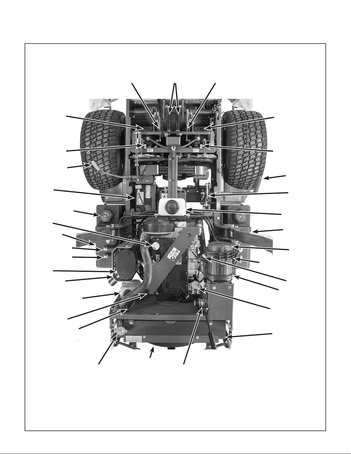
Component Identication
LH Transaxle
LH Transaxle
Lockout Arm
Parking Brake
Lever
Battery
Fuel Tank Cap
Oil Fill
Fuel Tank
LH Transmission
Control Rod
Steering Lever
Spring/Dampeners
RH Transmission
Control Rod
RH Transaxle
RH Transaxle
Lockout Arm
PTO Clutch
Lever
Clutch
Linkage
Transaxle Oil
Expansion
Reservoir
Fuel Gauge
(Not Visible)
Fuel Return Line
Fuel Pickup Line
Mufer
Mufer Heat
Shield
Coolant
Recovery Tank
Oil Filter
(Not Visible)
Overow
Hose
Radiator Cap
Radiator
Fan
Top View (Body Raised)
Air Filter
Restriction Gauge
Air Filter
Cover
Fuel Tank Selector
Valve (Not Visible)
Dipstick
Enginaire™
Air Cleaner
Fuel Pump
(With Primer)
Radiator
NOTE: ROPS Top Bar Removed for Clarity
8
Page 13
Safety Instructions - Before Operating
Pay particular attention to any information labeled
DANGER, WARNING, CAUTION, IMPORTANT,
and NOTE in this manual.
When you see the Safety Alert Symbol ( ), read,
understand, and follow the instructions. Fail ure to
comply with safety instructions may result in personal injury.
The seriousness or degree of importance of each
type of information is dened as follows:
DANGER
An IMMEDIATE hazard that WILL result in
severe personal injury or DEATH, if warn ing is ignored and proper safety precautions are not taken.
WARNING
A POTENTIAL hazard that COULD result in
severe personal injury or DEATH, if warning is ignored and proper safety precautions are not taken.
Walker Manufacturing cannot predict every potentially dangerous situation. Therefore, items labeled
as such in this manual do not cover all conceivable
situations. Any person using procedures, tools, or
control techniques not recommended by Walker
Manufacturing must take full responsibility for safety.
The Walker Rider Lawnmower has been designed
with many safety features to protect the operator
from personal harm or injury. However, it is necessary
for the operator to use safe operating procedures at
all times. Failure to follow safety instructions con-
tained in this manual may result in personal injury or damage to equipment or property.
If you have any questions concerning setup, operation, maintenance, or safety, please contact your
authorized Walker Mower dealer or call Walker
Manufacturing Company at (970) 221-5614.
BEFORE OPERATING
1. Read and understand the contents of this
Operator’s Manual before starting and operating the machine. Become thoroughly famil-
iar with all machine controls and how to stop the
machine and disengage the controls quickly.
Replacement Operator’s Manuals are available
by sending the Model and Serial Number to:
Walker Manufacturing Company
5925 East Harmony Road
Fort Collins, CO 80528
CAUTION
Possible hazards or unsafe practices that
MAY result in MODERATE personal injury
or property damage, or machine damage, if
warning is ignored and proper safety precautions are not taken.
IMPORTANT: Identifies mechanical information
demanding special attention, since it deals with the
possibility of damaging a part or parts of the machine.
NOTE: Identies information worthy of special
attention.
2. Never allow children to operate rider mower.
Do not allow adults to operate without proper
instruction.
3. Clear the area to be mowed of any foreign
objects which may be picked up and thrown by
cutter blades. Pick up all sticks, stones, wire,
and any other debris.
4. Keep everyone, especially children and pets, a
safe distance away from the area being mowed.
Do not mow with bystanders in the area.
5. Do not operate the machine barefoot or wearing
sandals, sneakers, tennis shoes, or similar
light weight footwear. Wear substantial pro-
tective footwear.
9
Page 14
Safety Instructions - Before Operating
6. Do not wear loose tting clothing that could get
caught in moving parts. Do not operate this machine while wearing shorts; always wear ade-
quate protective clothing, including long
pants. Wearing safety glasses, safety shoes,
and a helmet is advisable and required by some
local ordinances and insurance regulations.
7. Prolonged exposure to loud noise can cause
impairment or loss of hearing. Operator hear-
ing protection is recommended. Wear a suitable hearing protective device, such as earmuffs or earplugs.
8. Keep all protective shields and safety de-
vices in place. If a protective shield, safety
device, or decal is damaged, unusable, or missing, repair or replace it before operating the
machine.
9. Be sure interlock switches are functioning
correctly, so the engine cannot be started unless the Forward Speed Control lever is in the
NEUTRAL-PARK position, and the PTO clutch
is in the DISENGAGED position. Also, the engine should stop if the operator lifts off the seat
with either the Forward Speed Control (FSC)
out of the NEUTRAL-PARK position or the PTO
clutch in the ENGAGED position.
11. Never attempt to make any adjustments
while the engine is running, except where
spe cically instructed to do so.
12. The electrical system battery contains sulfuric
acid. Avoid any contact with skin, eyes, and
clothing. Keep the battery and acid out of reach
of children.
WARNING
This product can expose you to chemicals
including Di-(2-ethylhexyl) phthalate which
is known to the State of California to cause
cancer, and Di-(2-ethylhexyl) phthalate,
which is known to the State of California
to cause birth defects or other reproductive harm. For more information go to
www.P65Warnings.ca.gov.
NOTE: There is a 1/2 second time delay func-
tion on the seat switch to avoid engine power
interruption when driving over bumps.
10. Handle diesel with care:
a. Use an approved fuel container.
b. Never add fuel to a running engine or hot
engine (allow hot engine to cool several
minutes).
c. Keep matches, cigarettes, cigars, pipes,
open ames, or sparks away from the fuel
tanks and fuel container.
d. Always ll the fuel tank(s) outdoors using
care. Fill to about one inch from the top of
the tank. Use a funnel or spout to prevent
spilling.
e. Replace the machine fuel cap(s) and con-
tainer cap securely and clean up any spilled
fuel before starting the engine.
10
Page 15
Safety Instructions - Operating
WARNING
● Always keep the ROPS roll bar in the up-
right and locked position when operating.
● Always use the seat belt when the roll bar
is upright.
● Only lower the roll bar when absolutely
necessary for overhead clearance.
● Never use the seat belt when the roll bar
is lowered.
1. Operate the mower only in daylight or in
good articial light with good visibility of the area
being mowed.
2. Sit on the seat when starting the engine and
operating the machine. Keep feet on the deck
footrests at all times when the tractor is moving
and/or mower blades are operating. Never op-
erate the tractor without a deck or implement installed.
3. For a beginning operator, learn to steer (maneuver) the tractor with a slow engine speed
before attempting any mowing oper ation.
Be aware that, with the front mounted mower
conguration, the back of the tractor swings to
the outside during turns.
5. In case the transmission drive belt breaks during operation, and if the machine is on a slope,
the machine will freewheel down the slope. To
maintain control, immediately (1) Release the
steering levers and simultaneously (2) Move
the FSC to the NEUTRAL-PARK position.
When the machine is stopped or moving slowly,
engage the parking brake.
NOTE: The emergency stop procedure is exactly the same procedure used to normally stop
and park the machine.
6. Disengage the blade clutch and put the FSC in
the NEUTRAL-PARK position before starting
the engine (an ignition interlock switch normally
prevents starting of the machine if these controls are in the OPERATING position).
7. Do not operate machine if the operator pres-
ence safety switch system is not working.
Verify proper operation by having the operator
lift off the seat with the engine running and moving two controls, one at a time; (1) Move the
FSC lever out of the NEUTRAL-PARK position,
and (2) Engage the PTO Clutch. Moving either
control should stop the engine after a 1/2 second delay.
8. Do not run the engine in a conned area
without adequate ventilation. Exhaust fumes
are hazardous and can be deadly.
9. Do not carry passengers - maximum seating
capacity is one (1) person.
DANGER
Do not mow around overhanging tree
branches or bushes at the same height as
the operator’s torso and head where inadvertent contact may cause injury.
4. Remember, for an emergency stop, the forward
motion of the tractor can always be stopped by
pulling the Forward Speed Control (FSC) into
the NEUTRAL-PARK position.
10. Watch for holes, rocks, and roots in the terrain
and for other hidden hazards. When mowing
tall grass, mow higher than desired to expose
any hidden obstacles. Then, clean the area and
mow to the desired height.
11. Avoid sudden starts or stops. Before back-
ing the machine up, look to the rear to be sure
no one is behind the machine. Watch carefully
for trafc when crossing or working near roadways.
12. When moving forward, do not suddenly put the
tractor in reverse by rapidly pulling on the steering levers, especially when going downhill, as
this can lift the tractor tail wheel off the ground
and set up a bucking motion due to operator
overcontrol. If bucking does occur, immediately
stop the bucking action by pulling the Forward
Speed Control (FSC) lever into the NEUTRAL-
PARK position.
11
Page 16

Safety Instructions - Operating
13. Disengage the blade drive when transporting
the machine across drives, sidewalks, etc.
Never raise the mower deck while blades are
rotating.
DANGER
Do not mow or drive the tractor within 5
feet (1.5 meters) of an embankment or retaining wall with drop off.
14. The maximum recommended slope operating angle is 15 degrees or 26% grade. When
operating the machine on a slope, reduce
speed and use caution to start, stop, and maneuver. To prevent tipping or loss of control of
the machine, avoid sharp turns or sudden
changes in direction. Do not operate the ma-
chine on a slope greater than 15 degrees.
15. Never adjust cutting height with the engine
running. Before adjusting cutting height or
servicing, disengage the blade clutch (PTO),
stop the engine, and remove the ignition key.
Wait for all movement to stop before getting off
the seat.
NOTE: The blade/PTO brake should normally
stop drive line rotation within ve (5) seconds of
dis engaging the PTO clutch.
16. For side discharge mower decks, do not oper-
ate with the grass deector shield removed.
Keep the deector in the low est possible position.
17. When using the tilt-up deck, observe the fol-
lowing:
18. In case of a clogged or plugged mower deck:
a. Disengage the blade clutch (PTO), engage
the parking brake, and turn the engine off
before leaving the seat.
b. LOOK to make sure blade drive shaft
move ment has stopped before trying to unclog the system.
c. Never place hands under the deck - use a
stick or similar tool to remove clogged
ma terial.
19. If the cutting blades strike a solid object or the
machine begins to vibrate abnormally,
immediately disengage the blade clutch
(PTO), stop the engine, and wait for all moving parts to stop. Thoroughly inspect the
mower and repair any damage before restarting
the engine and operating the mower. Make
sure cutter blades are in good condition and
blade nuts are torqued to 60 lb·ft (81 N·m) for
gear driven decks, and blade bolts torqued to
70 lb·ft (95 N·m) for belt driven decks.
20. Do not touch the engine or mufer while the
engine is running or immediately after stopping the engine. These areas may be hot
enough to cause serious burns.
21. Never remove the radiator pressure cap
when the engine is hot (hot water may spray
and cause burns).
22. Do not use ether or any starting uid to assist
starting the engine in cold weather.
23. When leaving the machine unattended, disen-
gage the blade clutch (PTO), stop the engine, and remove the key.
12
a. Do not move tractor with deck in tilt-up
position.
b. Never tilt body forward with deck in tilt-up
position.
Page 17

Safety Instructions - Maintenance
1. To prevent accidental starting of the engine
when servicing or adjusting the machine, remove the key from the ignition switch.
2. To reduce re hazards, keep the engine free
of grass, leaves, excessive grease, and dirt.
3. Keep all nuts, bolts, and screws tight to ensure
the machine is in a safe, working condition.
Check the blade mounting bolts frequently,
mak ing sure they are tight.
4. Perform only maintenance instructions de-
scribed in this manual. Unauthorized mainte-
nance operations or machine modications
may result in unsafe operating conditions.
5. If the engine must be running to perform a maintenance adjustment, keep hands, feet, and
clothing away from moving parts. Do not wear
jewelry or loose clothing.
6. Always use the proper engine service
manual when working on the engine.
Unauthorized maintenance operations or
modications to the engine may result in unsafe
operating conditions.
12. Use care when charging the battery or per-
forming maintenance on the battery and electrical system:
a. Make sure the battery charger is unplugged
before connecting or disconnecting cables
to the battery.
b. Charge the battery in a well-ventilated
space, so gases produced while charging
can dissipate. Make sure the battery vents
in the caps are open.
c. Keep sparks, ames, and smoking ma-
teri als away from the battery at all times. To
avoid sparks, use care when removing
bat tery cables from posts.
d. Disconnect both battery cables before
unplugging any wiring connectors or making repairs on the electrical system.
IMPORTANT: Keep all applicable manuals immediately accessible to anyone who may operate or service this machine.
7. The fuel oil injection system operates under
high pressure and can penetrate the skin and
result in serious injury. Unqualied persons
should not remove or attempt to adjust the fuel
injector pump, nozzle, or any part of the fuel injection system.
8. Altering the equipment or engine in any manner which adversely affects its operation, performance, durability, or use will VOID the war-
ranty and may cause hazardous conditions.
9. Never attempt to disconnect any safety devices
or defeat the purpose of these safety devices.
10. Do not change the engine governor settings or
overspeed the engine. The governor has been
factory-set for maximum-safe engine operating
speed.
11. Use genuine factory replacement parts.
Sub stitute parts may result in product malfunction and possible injury to the operator and/or
others.
13
Page 18
Safety Instructions
SAFETY, CONTROL, AND INSTRUCTION DECALS
Safety, Control, and Instruction Decals are installed on the machine;
if any are missing, illegible, or damaged, a replacement should be ordered and installed before
putting the machine into operation. The Decal Part Number is listed below and in the Parts Manual.
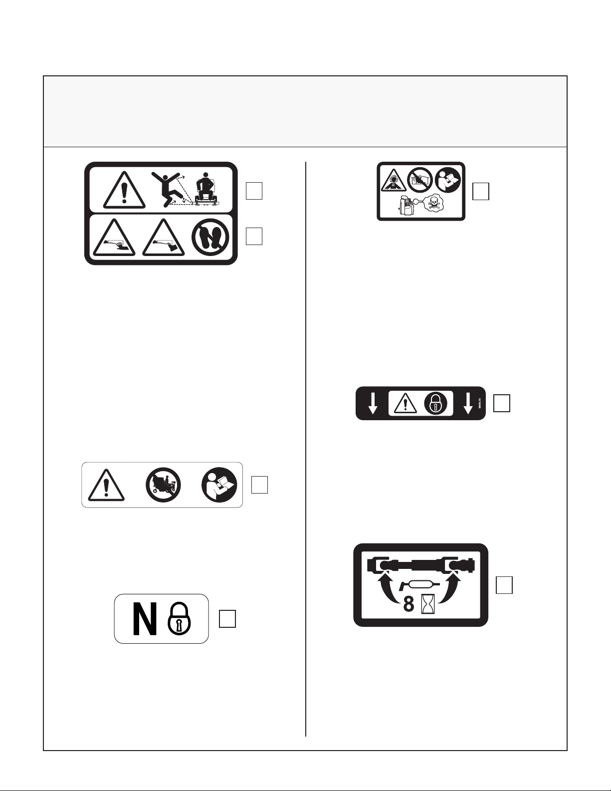
1.
2.
8600-28
Location: Each End of Mower Deck
Part Number: 8600-28
1. Warning – thrown object hazard.
● Keep bystanders away from the machine
when operating.
● Clear lawn of debris before operating.
● Keep any discharge deector in place and in
the lowest position.
2. Warning – rotating mower blades are a cutting/
dismemberment hazard to hands and feet.
● Keep all body parts away from rotating mow-
er blades.
• Do not step on end of deck.
1.
1.
8600-12
Location: Engine Brace
Part Number: 8600-12
1. Warning – carbon monoxide (CO) poisoning
hazard.
● CO emitted by a running engine can be
deadly.
● Do not operate indoors or in other enclosed
areas.
1.
Location: Deck Carrier Frame
Part Number: 8600-15
1. Warning – lock deck tilt-up hinge before operating the machine.
8600-14
Location: Deck Carrier Frame
Part Number: 8600-14
1. Warning – do not operate the machine with the
deck tilted up.
9804-1
1.
Location: Chassis Member Behind Transaxles
Part Number: 9804-1
1. Neutral Lock
● Lift and move back to engage step to unlock
transaxle and allow machine to freewheel.
14
1.
8746-2
Location: PTO Guard on Deck
Part Number: 8746-2
1. Grease PTO shaft joints every 8 hours.
Page 19
Safety Instructions
SAFETY, CONTROL, AND INSTRUCTION DECALS
Safety, Control, and Instruction Decals are installed on the machine;
if any are missing, illegible, or damaged, a replacement should be ordered and installed before
putting the machine into operation. The Decal Part Number is listed below and in the Parts Manual.
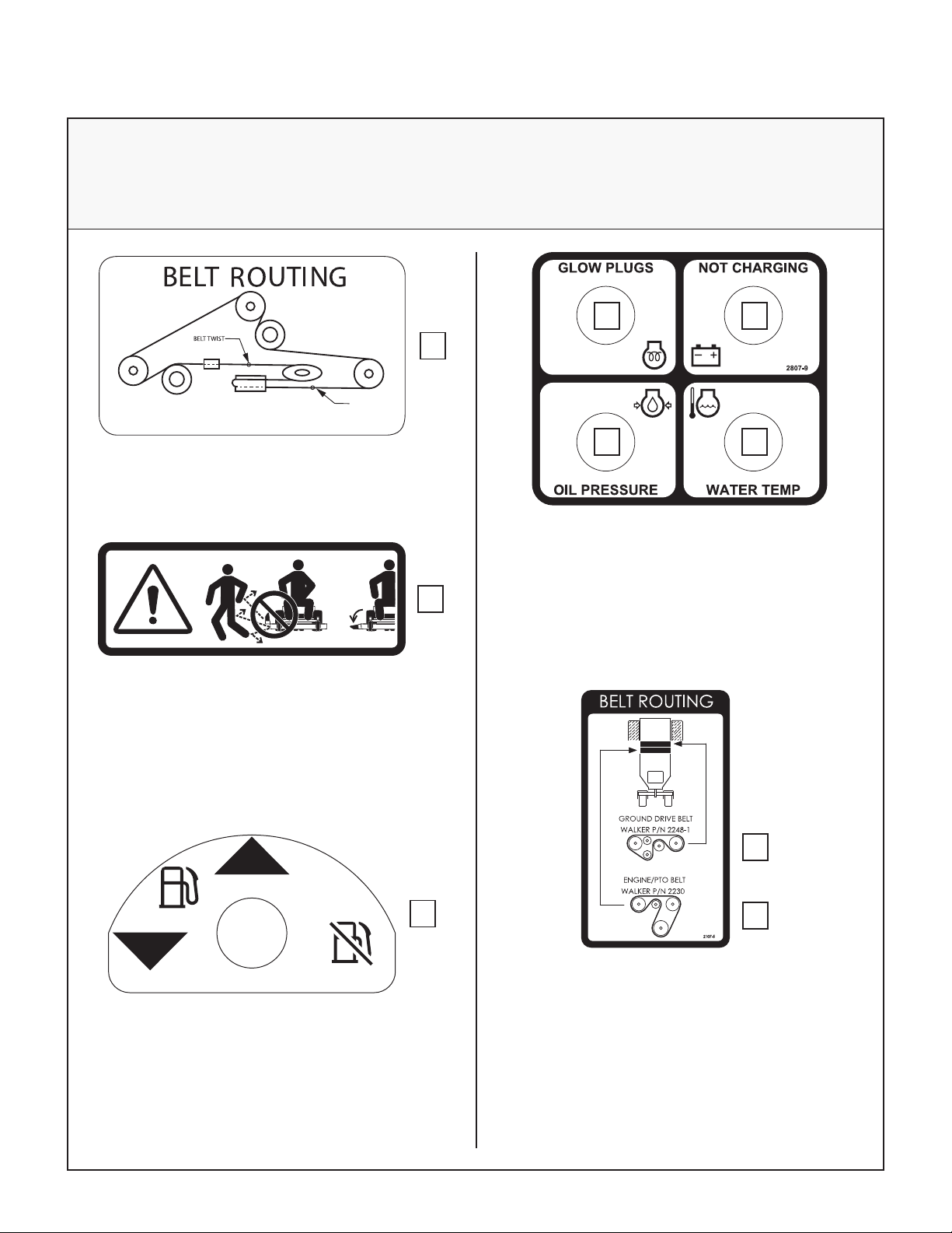
DR64 BELT P/N 2731-5
1. 2.
1.
BELT TWIST
2749-7
Location: Deck Housing Under Footrest
Part Number: 2749-7 (DR64)
1. Deck drive belt routing.
Location: Deck Discharge Shield (DS60)
Part Number: 5848-3
1. Warning – thrown object hazard.
● Always keep the discharge shield in the low-
est position when operating.
● Do not remove the discharge shield.
L
4.3.
Location: Front of Body on Right Side
Part Number: 2807-9
1. Glow plugs activation indicator light.
1.
5848-2
2. Battery charging system malfunction indicator
light.
3. Low engine oil pressure warning light.
4. High engine coolant temperature warning light.
1.
R
2010-17
Location: Adjacent to Right Fuel Tank
Part Number: 2010-17
1. Fuel tank selector/fuel shut-off valve.
1.
2.
Location: Underside of Panel Behind
Operator Seat
Part Number: 2107-5
1. Ground drive belt routing.
2. PTO clutch belt routing.
15
Page 20

Safety Instructions
SAFETY, CONTROL, AND INSTRUCTION DECALS
Safety, Control, and Instruction Decals are installed on the machine;
if any are missing, illegible, or damaged, a replacement should be ordered and installed before
putting the machine into operation. The Decal Part Number is listed below and in the Parts Manual.
1.
Location: Top of Deck Housing
Part Number: 8653-1
1. Warning – secure deck with straps and engage
parking brake before transporting or trailering
with deck tilted up.
4.75
4.25
3.75
3.25
2.75
2.25
1.75
5.0
127
121
4.5
114
108
4.0
102
95
83
70
57
3.5
3.0
89
2.5
76
64
2.0
51
44
1.5381.0
1.25
32
25
1.
inch
+
mm
-
2748-1
Location: Deck Height Adjuster
Part Number: 2748-1
1.
8600-2
Location: Flex Coupler Guard in Front of Engine
Part Number: 8600-2
1. Warning – entanglement and cutting/dismemberment hazards.
● Keep away from rotating shafts, belts, and
other components.
1.
Location: Radiator
Part Number: 2427-9
1. Move pin to desired height of cut.
16
Page 21
Safety Instructions
SAFETY, CONTROL, AND INSTRUCTION DECALS
Safety, Control, and Instruction Decals are installed on the machine;
if any are missing, illegible, or damaged, a replacement should be ordered and installed before
putting the machine into operation. The Decal Part Number is listed below and in the Parts Manual.
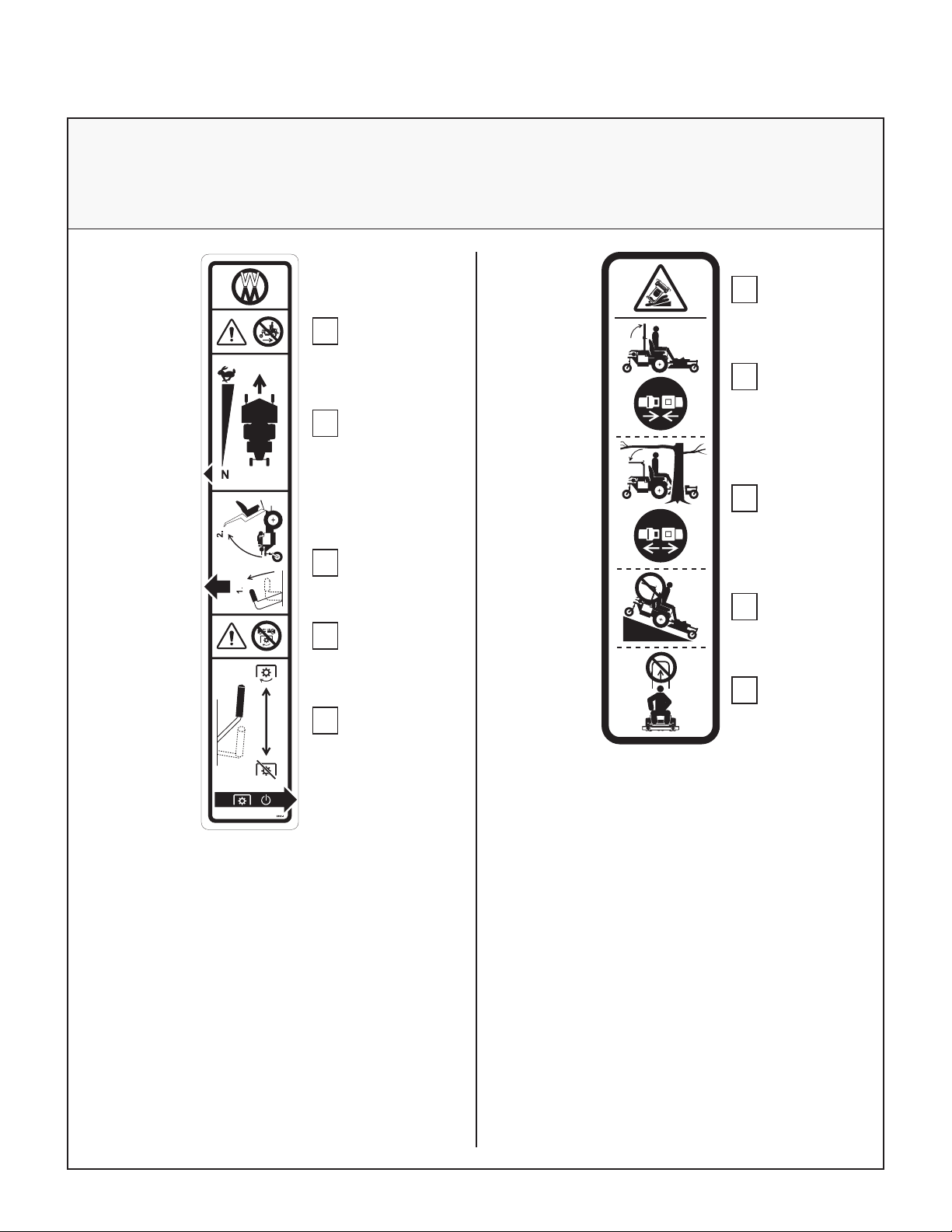
1.
1.
2.
2.
3.
3.
4.
5.
Location: Right Fender
Part Number: 2802-4
1. Warning – do not operate the machine without a
deck or other implement attached.
2. Forward Speed Control
● Move lever forward to increase speed; back
to stop.
3. Body Tilt Latch
● Tilt utility bed back.
● Raise lever to release.
● Lift at back of body to raise.
4. Warning – do not engage PTO clutch with PTO
shaft disconnected.
5. PTO Clutch Lever
● Move lever forward to engage PTO clutch;
back to disengage.
4.
5.
5685-3
Location: ROPS Roll Bar
Part Number: 5685-3
1. Warning – roll-over/crushing hazard.
● Do not operate the machine on steep slopes
or near drop-offs.
● Avoid quick and/or sharp turns when operat-
ing on slopes.
2. During normal operation always keep the ROPS
locked fully upright and use the seat belt.
3. Never use the seat belt if the ROPS is not locked
fully upright.
4. Do not operate the machine on slopes if the
ROPS is not locked fully upright.
5. Do not remove the ROPS.
17
Page 22
Safety Instructions
SAFETY, CONTROL, AND INSTRUCTION DECALS
Safety, Control, and Instruction Decals are installed on the machine;
if any are missing, illegible, or damaged, a replacement should be ordered and installed before
putting the machine into operation. The Decal Part Number is listed below and in the Parts Manual.
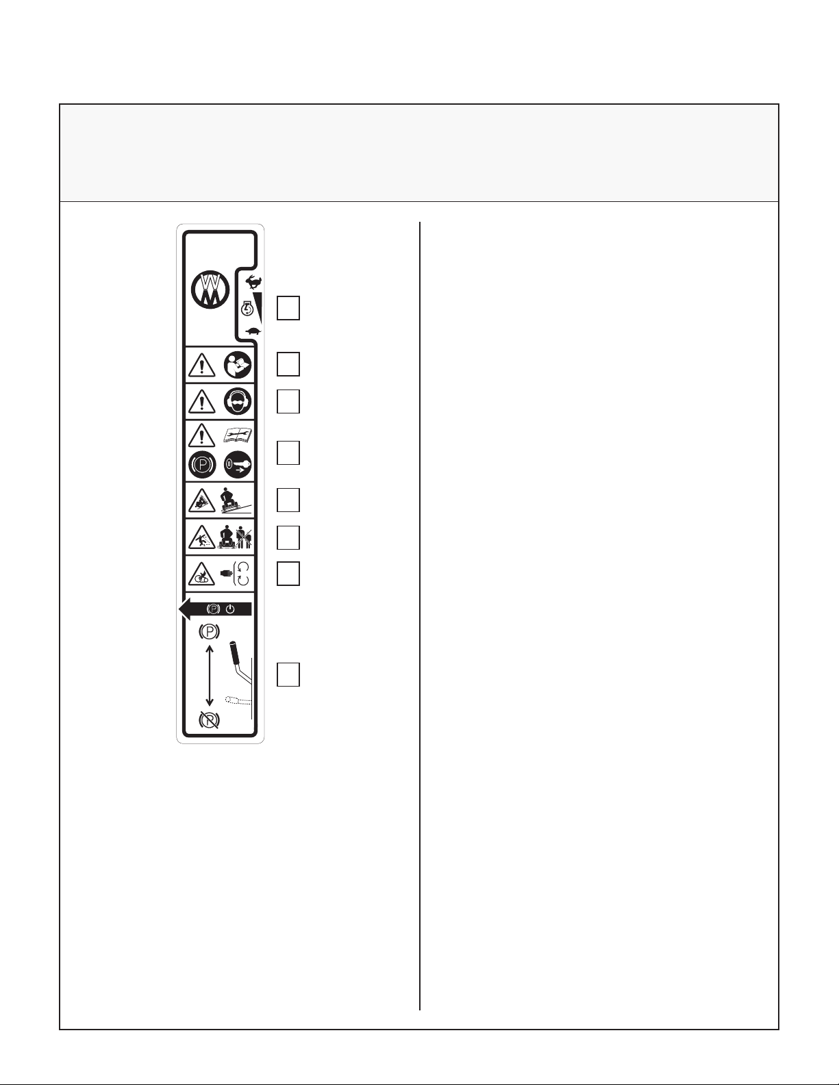
1. 2.
<15°
1.
2.
3.
4.
5.
6.
7.
1. Throttle
● Move lever forward to increase engine
speed; back to idle.
2. Warning – read Operator’s Manual before operating the machine.
3. Warning – wear eye and ear protection when operating the machine.
4. Warning – read Operator ’s Manual before servicing or performing maintenance.
● Engage parking brake.
● Remove ignition key.
5. Warning – roll-over hazard.
● Do not operate on slopes greater than 15
degrees.
6. Warning – thrown object hazard.
● Keep bystanders away from the machine
when operating.
7. Warning – entanglement hazard.
● Keep all guards in place while engine is run-
ning.
8. Parking brake
● Move lever forward to engage Parking
Brake; back to disengage.
Location: Left Fender
Part Number: 2802-5
18
8.
2802-5
Page 23
Assembly Instructions
SETUP INSTRUCTIONS
Walker Mowers are shipped partially assembled to
our distribution network, and are typically assembled by the selling dealer. For any additional assembly besides the following, contact your Walker
dealer.
Battery Service
Raise the utility bed and mower body up for battery
access. Check the battery for electrolyte level and
charge. The electrolyte level should be at the
bottom of the vent wells [1/4 to 1/2 in. (6 to 13 mm)
above plates]. If the specic gravity is less than
1.225, the battery needs charging. If the battery has
been shipped dry, or is wet but needs service, refer
to the following instructions.
RH Drive
Tire (Ref)
Battery
Dry Battery Service
DANGER
Activating a battery can be dangerous.
The battery should be taken to a reliable
service station, battery store, or power
equipment dealer where a trained technician can activate the battery safely. DO
NOT attempt to activate the battery unless
you are experienced in battery service
work. The following activation and charging instructions are provided for use by a
trained battery technician.
DANGER
Battery electrolyte is a poisonous and corrosive sulfuric acid solution.
● Avoid spillage and contact with skin,
eyes, and clothing - causes severe burns.
Battery Location
IMPORTANT: Make sure battery is securely
mounted in the frame. A loose battery may cause
damage to the case resulting in acid leakage and
se vere damage to the machine. A hazard may be
cre ated by damage to critical working parts and
safety systems.
IMPORTANT: Never disconnect battery while engine is running.
Wet Battery Service
If the battery has been shipped wet, but the electrolyte level is low or the battery needs to be charged
then:
1. Fill each battery cell with distilled water to the
bottom of the vent wells.
2. Charge battery. Refer to Battery Charging in this
section.
● To prevent accidents, wear safety gog-
gles and rubber gloves when working with
electrolyte.
● Neutralize acid spills with baking soda
and water solution.
To ll (activate) battery with electrolyte (if battery has
been shipped dry):
1. Remove the battery hold-down bar, disconnect
the battery cables and lift the battery out of the
tray.
IMPORTANT: Battery must be removed from
the mower before lling with electrolyte.
IMPORTANT: Obtain and use only battery
grade sulfuric acid electrolyte with a 1.265 specic gravity to activate the battery. DO NOT use
water or any other liquid during initial activation.
2. Remove the ller caps and carefully ll each cell
until the electrolyte is just above the plates.
3. After the battery is lled with electrolyte, replace
the ller caps and charge the battery. Refer to
Battery Charging.
19
Page 24

Assembly Instructions
Battery Charging
DANGER
BATTERIES PRODUCE EXPLOSIVE GASES
● Charge the battery in a well-ventilated
area, so that gases produced while charging can dissipate.
WARNING
Make sure the battery cap vents are open.
Improper venting of the battery COULD
cause a battery explosion.
● Keep sparks, ames, and smoking mate
rials away from the battery at all times.
● Make sure the battery cap vents are open
after the battery is lled with acid (check
manifold vent on each cap).
● Make sure the battery charger is un-
plugged before connecting or disconnecting cables to the battery.
1. Charge the battery at 15 amps for 10 minutes.
DO NOT exceed 20 amps maximum recom-
mended charging rate. Charge until specic
gravity is at least 1.250. Total charging time
should not exceed one (1) hour.
2. After charging the battery, adjust the electrolyte
level to the bottom of the vent wells [1/4 to 1/2 in.
(6 to 13 mm) above the plates].
IMPORTANT: DO NOT overll the battery.
Electrolyte will overow through the vented
caps onto parts of the machine and WILL result
in severe corrosion.
Battery Clamp Secured
by Wing Nut(s)
(+) Battery Cable
Connection
Battery Installation
(Viewed from RH Side)
Mower Deck Assembly
Deck Caster Wheels Installation
1. Remove the bolts and washers from each deck
caster wheel.
2. Install wheel on fork using bolts and washers.
3. Tighten the bolts and washers.
3. Install battery.
Battery Installation
IMPORTANT: Make sure battery is securely mounted in the frame. A loose battery may cause damage
to the case resulting in acid leakage and severe
damage to the machine. A hazard may be created
by damage to critical working parts and safety systems.
Install the battery in the mower as shown in Battery
Installation photo. Connect the positive (+) rst and
then the negative (-) cable to the proper battery terminal [red cable and boot connects to the Posi-
tive (+) terminal]. Slide the rubber boot up and over
the battery post, making sure it covers the post completely to prevent an electrical short.
20
Deck Caster Wheel Installation
Page 25

Assembly Instructions
Deck Discharge Deector Shield Installation (DS60)
Attach the side discharge deector shield using two
(2) 3/8-16 x 1-1/4 in. bolts, 3/8-16 ESNA nuts, and
3/8 in. wave spring washers. The wave washers t
between the two hinging surfaces. Tighten the nuts
until the shield moves freely but is not loose.
WARNING
DO NOT operate the machine without the
grass deector shield attached and in the
lowest possible position.
Attach Shield
Tilt-Up Roller Wheel Installation
Mount the two (2) tilt-up roller wheels on the brackets on the rear skirt of the deck housing using the
axle spacer tube, 3/8-16 x 3 in. bolt and 3/8-16 Whiz
locknut. Tighten the bolt until the wheel rolls freely,
but is not loose.
Roller
Wheel
Roller Wheel Installation (Typical DS60 Shown)
Mower Deck Installation on Tractor
Deck Discharge Shield Installation
PTO Shaft Guard Installation
Position the shaft guard as shown and mount with
two (2) 1/4-20 x 1/2 in. bolts.
Carrier Frame
Tube Sockets
Attach
Guard
PTO Shaft Guard Installation
Deck Installation
1. Lightly grease each deck support arm (2) on the
tractor. Refer to Mower Deck Installation
photo for location of deck support arm.
Deck Support
Arms
Rubber Debris
Guard
Mower Deck Installation
2. First, engage the LH deck carrier frame tube
socket on the LH tractor support arm and then
the RH arm into the RH tube socket. Slide the
deck onto the support arms and install lynch
pins to secure deck. Two (2) lynch pins are included in Owner’s Packet of materials.
21
Page 26
Assembly Instructions
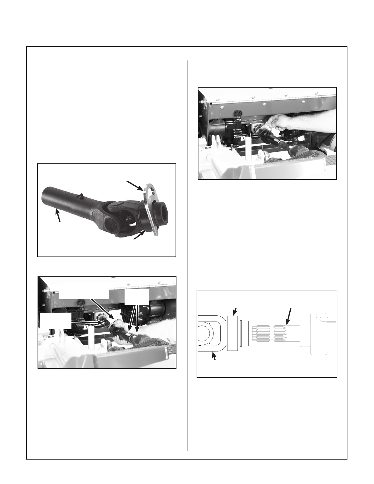
3. Retract the spring-loaded quick disconnect ring
on the PTO Coupler and insert the Coupler
Installation Tool (provided in Owner’s Packet) as
shown in the PTO Coupler Installation Tool
photo.
NOTE: The Coupler Installation Tool is provided
for convenience, but is not required for installation.
4. Unhook lower edge of rubber debris guard and
raise for access to the tractor PTO shaft. Refer
to Mower Deck Installation photo for location
of debris guard.
Coupler
Installation Tool
PTO Coupler
Tube
Retract Spring-Loaded
Quick Disconnect Ring
PTO Coupler Installation Tool
Coupler
Installation Tool
Align
Arrows
6. Remove Coupler Installation Tool from quick
disconnect ring and make sure the ring has
“snapped” securely on the spline shaft.
Coupler Installation Tool Removal
(Shown with Debris Guard Removed for Clarity)
IMPORTANT: DO NOT operate tractor with
Coupler Installation Tool installed.
IMPORTANT: To prevent damage to the mower, make sure the PTO quick disconnect is securely locked on the tractor, with the locking
balls fully seated in the groove and the ring in
the locked position (refer to the Quick Discon-
nect Ring “Locked” Position illustration). After installation, pull on the PTO coupler to check
for security.
Coupler Ring in
Released Position
PTO Drive
Shaft
Tractor
PTO Shaft
PTO Shaft Connection
(Shown with Debris Guard Removed for Clarity)
5. Reaching under the tractor, slide the PTO coupler tube onto the deck drive shaft (align arrow
decals), then install the coupler quick disconnect
onto the tractor PTO drive shaft. Refer to the
PTO Shaft Connection photo.
22
PTO Coupler
U-Joint
Quick Disconnect Ring “Released” Position
Page 27

Assembly Instructions
Internal Balls
Locked on Shaft
PTO Coupler
U-Joint
Quick Disconnect Ring “Locked” Position
7. Raise the mower body (instead of lifting the front
of deck) and clip the counterweight springs to
the receptacle on front of body. Lower the body
to tension the springs. (Refer to Deck Counter-
weight Spring Installation photo.)
8. With the counterweight springs connected, the
weight on the deck caster wheels should be
190 to 230 Ib (86.2 to 104 kg); this adjustment is
preset at the factory.
Coupler Ring in
Locked Position
Counterweight Springs
Clip Onto Body With
PTO Drive
Shaft
Body Tilted Up
Deck Leveling
The mower deck and support frame are jig welded
and the deck support linkage is factory adjusted.
Within normal tolerances, very little, if any, adjustment should be required to level the deck. Tire size
and pressure will affect the levelness of the deck.
Assure that all tires (tractor and deck caster
wheels) are properly inated prior to checking
deck levelness or performing the deck leveling
procedure.
Measuring Deck Levelness
1. Position the mower on a smooth, level surface,
and set the deck height to the most common cutting position. Refer to ADJUSTING CUT-
TING HEIGHT in Operating Instructions.
2. See the Deck Leveling illustration for side-toside and front-to-back deck level measurement
points. Side-to-side measurements should not
vary more than 1/8 in. (3 mm). Front-to-rear
measurements should have the rear 1/4 in.
(6 mm) to 3/8 in. (10 mm) higher than the front.
If either set of measurements are not within
tolerance, perform the Deck Leveling Procedure.
Lynch Pins
Lock Deck on
Support Arms
(Not Visible)
Deck Counterweight Spring Installation
23
Page 28

Assembly Instructions
Deck Leveling Procedure
1. Position the mower on a smooth, level surface,
and set the deck height to the most common
cutting position. Refer to ADJUSTING CUT-
TING HEIGHT in Operating Instructions.
WARNING
The machine must be shut off during this
procedure.
2. Place a block of sufcient height under the left
rear corner of the deck housing to remove tension from the left rear deck support chain. Detach the left rear deck support chain by removing the upper bolt from the height adjuster arm.
Remove the block and let the deck hang from
the remaining three support chains.
3. Measure the side-to-side level of the deck by
measuring from the ground to the top of the
deck housing at the front corners of the deck as
shown in the Deck Leveling illustration. The
side-to-side measurements should not vary by
more than 1/8 in. (3 mm). If necessary, raise or
lower the left and/or right front support chain
clevises to level the deck.
4. Measure the front-to-rear level of the deck using
a straight edge as shown in the Deck Leveling
illustration. The rear measurement should be
1/4 in. (6 mm) to 3/8 in. (10 mm) higher than the
front measurement. If necessary, adjust the
right side height adjustment rod by lengthening
it to lower the back of the deck, or shortening it
to raise the back of the deck.
5. With the side-to-side and front-to-rear deck level correct, reattach the left rear support chain
that was removed in step 2. Adjust the left side
height adjustment rod to equalize the left rear
and right rear support chain tension.
6. Assure that all fasteners are tight and replace
any guards removed during the leveling procedure.
Right Side
Measurement
Point
Ground
Right Support
Chain Clevis
Right Height
Adjustment Rod
Left Rear Deck Support
Chain (Remove Upper
Bolt for Leveling)
Left Height
Adjustment Rod
Left Support
Chain Clevis
Front
Measurement Point
Approx. 36 in. (914 mm)
Long Straight Edge
Rear
Measurement
Point
Left Side
Measurement Point
24
Deck Leveling
Page 29

Assembly Instructions
PREOPERATING CHECKLIST
Before operating the mower for the rst time, and as
a routine before daily operations, it is important to
make sure the mower is properly prepared and
ready for operation. The following is a list of items
to be checked. (For a mower with frequent operation, some of these items will not need to be
checked every day, but the operator should be
aware of the condition of each.)
For proper fuel and lubricants refer to Specications.
FILL FUEL TANKS
Fill the fuel tanks with clean, fresh fuel. Clean diesel
fuel is particularly important since contaminated fuel
will damage the fuel injectors and injection pump.
NOTE: It may be necessary to use the fuel pump
primer to bleed (purge out air bubbles) the diesel fuel
injector system when initially lling an empty tank.
Refer to Fuel Pump Priming instructions in the Op-
erating Instructions.
DANGER
Handle diesel fuel with care. Use safe
refueling procedures:
● DO NOT ll fuel tanks with the engine
running.
CHECK ENGINE CRANKCASE OIL LEVEL
Check the engine crankcase oil level before use and
after each 8 hours of continuous operation. Refer
to LUBRICATION for Checking Engine Crankcase
Oil Level in Maintenance Instructions.
CHECK AND SERVICE ENGINE AIR CLEAN-
ER SYSTEM
● Check air lter restriction gauge to make sure the
yellow indicator disk is in the safe operating
(green) range.
● Check condition, cleanliness, and security of the
complete air cleaner system (inspect air lter
every 100 hours). For detailed procedures,
refer to CLEANING the Engine Air Cleaner
System in Maintenance Instructions.
CHECK ENGINE COOLING SYSTEM
● Check the radiator air intake screen to make
sure the screen is clean and free of obstruction.
Also, the radiator cooling ns should be in-
spected and cleaned if there is any buildup of
dirt or debris. (Remove the intake screen
assembly to inspect and clean.)
● Check the coolant levels in the radiator and
overow tank. If additional coolant is needed,
refer to CHECKING/SERVICING the Engine
Cooling System in Maintenance Instructions.
● If the engine is hot, allow to cool before
refueling.
● Use an approved fuel container.
● Fuel the mower outdoors.
● DO NOT smoke while refueling.
● Avoid spilling fuel; use a funnel or
spout.
● DO NOT overll the fuel tanks; ll up to
about 1 in. (25 mm) below the top of tank.
IMPORTANT: DO NOT permit dirt or other foreign
matter to enter the fuel tanks. Wipe dirt from around
the ller cap(s) before removing. Use a clean fuel
storage container and funnel.
WARNING
DO NOT remove the radiator pressure cap
when engine is hot.
CHECK HYDROSTATIC TRANSAXLE OIL
LEVEL
Refer to LUBRICATION for Transaxle Fluid Level
in Maintenance Instructions.
CHECK SECURITY OF DRIVE TIRE MOUNT-
ING NUTS
The eight (8) Drive Tire mounting nuts should each
be torqued to 75 to 85 lb·ft (102 to 115 N·m).
25
Page 30

Assembly Instructions
2802-5
<15°
1. 2.
INSPECT FIVE (5) DRIVE BELTS
Engine/PTO (3), Ground Drive (1) and Deck Drive (1).
CHECK TIRE PRESSURE
Deck Caster Wheel = 20 PSI (137 kPa)
Drive = 15 PSI (103 kPa)
Tailwheel = 20 PSI (137 kPa)
CHECK FUNCTIONS OF WARNING LIGHTS
AND WARNING HORN
Turn the ignition key to the ON (RUN) position. Glow
Plug Activation Light, Low Engine Oil Pressure
Warning Light, Battery Charging System Malfunction Indicator Light, and Warning Horn should all
operate, indicating normal function.
CHECK FUNCTION OF SAFETY INTERLOCK
SWITCHES
Refer to Operating Instructions to check for proper
operation of safety switches, both during engine
starting and with the operator leaving the seat with
tractor moving forward or with mower blades engaged.
CHECK AND CLEAN GRASS BUILDUP
UNDERNEATH MOWER DECK
Refer to CLEANING the Grass Buildup in Mower
Deck Housing in Maintenance Instructions for deck
tilt-up and deck cleaning information.
Tilt Bar
Unlock Deck Arms for Deck Tilt-Up
3. Fit tilt bar into the socket on front of deck housing
and secure with hitch pin.
4. Remove footrest or, if equipped with adjustable
footrests, move the footrest to the full forward
locking position.
5. Raise deck to tilt-up position using tilt bar and
secure in position by inserting the deck hook in
the tilt-up latch on the tractor body as shown in
the Deck Secured in TILT-UP Position photo.
Before operating the mower, make sure to re-
engage the locking arms into the LOCKED
position after lowering the deck to the normal
operating position.
DANGER
Never operate cutter blades with deck in
raised position because it is hazardous.
The tilt-up deck can be secured in the raised position
using the following procedure:
1. Remove the tilt bar from the stowed position on
the carrier frame.
2. Use the tilt bar to release the two (2) deck locking arms as shown in the Unlock Deck Arms
for Deck Tilt-Up illustration.
26
CAUTION
Do not operate mower with deck tilt-up
pivot joint UNLOCKED. Make sure locking
arms are in the LOCKED position and the
tilt-up joint is rigid (locked).
DANGER
Do not operate the mower with deck in tiltup position. Do not move the tractor with
the deck in the tilt-up position.
Page 31

Assembly Instructions
Hitch Pin
CHECK MOWER BLADE CONDITION,
SHARPNESS, AND SECURITY OF MOUNTING
Tilt-Up Hook and
Latch Connected
Tilt-Up
Latch
Deck Secured in TILT-UP Position
Tilt-Up
Hook
Tilt Bar
The blade mounting nuts on gear driven decks
should be torqued to 60 lb·ft (81 N·m) and the blade
mounting bolts on belt driven decks should be
torqued to 70 lb·ft (95 N·m). If blade sharpening is
required, refer to CHECKING/SERVICING for
Sharpen Mower Blades in Maintenance Instruc-
tions.
ADJUST MOWER CUTTING HEIGHT, IF
REQUIRED
Refer to ADJUSTING CUTTING HEIGHT in Oper-
ating Instructions.
PERFORM ANY ADDITIONAL PROCEDURES
called for on the MAINTENANCE SCHEDULE
CHART in Maintenance Instructions.
27
Page 32

Operating Instructions
CONTROL IDENTIFICATION, LOCATION, AND
FUNCTION
CAUTION
Before operating the mower, become familiar with the location and function of all
operator controls. Knowing the location,
function, and operation of these controls
is important for safe and efcient opera
tion of the mower.
Ignition Switch
The ignition switch is located on the right front of the
body and is used to start and stop the engine. The
switch has three positions: “O” is the OFF position,
ON (RUN) is the position that activates the glow
plugs for preheat and the position the key returns to
after starting and “S” is the START position. When
starting the engine, (1) turn the key to ON (RUN) and
observe the glow plug activation light (this light may
not come on if the engine is hot) and (2) as soon as
the glow plug light goes off, immediately turn the
key clockwise to the “S” position. Do not hold the
key in the “S” position longer than 10 seconds.
If the engine does not start, return the key to the “O”
position for at least 60 seconds before making a
restart attempt. Prolonged cranking can damage
the starter motor and shorten battery life. Release
the key when the engine starts, and it will return to
the (ON/RUN) position. To stop the engine, rotate
the key counterclockwise to the “O” position.
NOTE: The duration of glow plug activation (preheat) is automatic and varies with engine temperature. The longest duration will be with a cold engine
and the warmer the engine, the shorter the time for
the glow plugs to cycle on and off. If the glow plugs
do not activate with a cold engine or the activation
light stays on, the engine needs to be serviced by
contacting your authorized Kohler engine dealer.
OFF
O
ON (RUN)
s
START
Forward Speed
Control (FSC)
Body
Latch
Blade Clutch
(PTO)
Ignition Switch
Circuit
Breaker(s)
Hourmeter
Ignition Switch
Parking
Brake
Parking
Brake
LH Side View
Throttle
Steering
Levers
Warning
Lights (4)
Warning Horn
28
Operating Controls
Page 33

Operating Instructions
Engine Throttle
The throttle control lever (red knob) is located on the
left side of the seat and is used to control engine
speed. Moving the lever forward toward the FAST
position increases engine speed; moving it back-
ward toward the IDLE position decreases engine
speed.
Throttle
Throttle Location
Body Latch
The front portion of the tractor body hinges forward
for maintenance access and is latched down in the
OPERATING position. To raise the body, rst tilt the
utility bed back, then pull back and up on body latch
and lift the body from behind the seat.
portional to the lever position; the further the lever is
advanced forward, the faster the tractor moves. It is
not necessary to hold the FSC in position since the
friction lock maintains the selected lever position.
Pulling back on the steering levers overrides the
FSC setting and slows or stops foward travel.
Releasing the steering levers allows the tractor to
resume forward travel at the speed set by the FSC
lever. To stop and park the machine, the FSC lever is
moved backward to the NEUTRAL-PARK position.
Fuel Pump Priming
The Kohler diesel engine is equipped with a mechanical fuel pump and in certain situations (running
out of fuel, changing the fuel lter, or other fuel system maintenance) the fuel system may need to be
primed by removing air trapped in the system. Fuel
pump priming should be used if the engine does not
start after a couple of 10 second cranking attempts.
NOTE: DO NOT use prolonged cranking to prime
the fuel system as this may damage the starter and
shorten battery life.
Use the following procedure to prime the fuel pump
and purge air out of the fuel system:
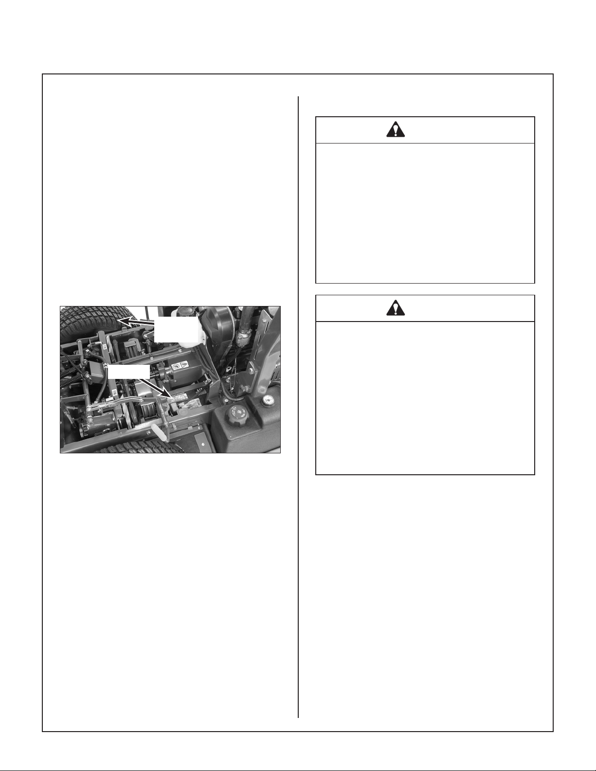
1. Loosen the bolt on the fuel injection pump return
hose where it attaches to the fuel lter housing
as shown.
Body
Latch
Body Latch
Forward Speed Control (FSC)
Forward Speed Control (FSC) has two functions:
One is to set forward travel speed, and the other is
to establish the NEUTRAL-PARK position. When
the FSC lever is moved into the FORWARD position,
a friction lock holds any forward speed setting from 0
to 10 mph (0 to 16 km/h). The ground speed is pro-
Fuel Injection Pump
Fuel
Filter
Air Bleed Bolt Location
2. Turn ignition key to ON to open the electric fuel
shutoff valve (do not crank or run engine).
3. Repeatedly stroke the Fuel Pump Primer lever
until fuel is owing out of the return hose tting.
(continued on next page)
Return Hose
Loosen Bolt to Bleed
Air From Fuel System
29
Page 34

Operating Instructions
Fuel Pump
Primer Lever
Fuel Pump Primer Lever
4. After bleeding the system, tighten the return
hose tting bolt securely.
Steering Levers
IMPORTANT: Stop the tractor completely before
engaging the parking brake. The parking brake
uses a positive mechanical lock similar to the PARK
posi tion on an automotive automatic transmission.
If the tractor is moving when the brake is engaged,
it will result in sudden stoppage and possible internal damage to the transaxle.
NOTE: If pressure on the parking brake (e.g. parked
on a hill) makes it impossible to release the parking
brake with the parking brake lever, move the mower
gently forward or backward to allow the brake detent
to release.
Each drive wheel is controlled by its own independent steering lever, for both steering function and
FORWARD/REVERSE motion. The FSC lever sets
the maximum forward speed, and also sets the forward position of the steering levers. The steering
levers operate only with a backward pulling movement of the lever, which causes the drive wheel for
that lever to rst slow down, stop, and then reverse
with a full backward lever stroke. The levers are released to the FORWARD position for “straight-
ahead” ground travel.
NOTE: Pushing forward on the steering levers will
not cause any change in tractor motion - there will
be no steering lever reaction and there will be no
machine damage.
Blade Clutch (PTO)
The blade clutch lever is located on the right side of
the seat behind the right fender and is used to engage and disengage the mower blades. The blade
clutch lever has two positions. Pushing the lever
DOWN engages the PTO that drives the mower
blades. Pulling the lever UP disengages the PTO
and engages the blade brake.
Engaged
Position
Parking Brake Engaged
Disengaged
Position
Parking Brake
The parking brake functions by locking a detent arm
to a cog in the hydraulic motor rotor. Moving the lever FOR WARD engages the parking brake; moving the lever BACKWARD releases the brake.
30
Parking Brake Disengaged
Page 35

Operating Instructions
Circuit Breakers
Two manual reset circuit breakers are located on the
front body. Each has a button that pops out if the
circuit breaker trips. The 10 amp circuit breaker protects the safety and ignition circuits. The 7 amp protects the indicator lamps and hourmeter.
Glow Plug Activation Light
The glow plug activation light indicates the glow
plugs are operating (preheating).
Battery/Charge Malfunction Light
The charge light indicates the electric system is not
being charged.
Oil Pressure Warning Light/Horn
The oil pressure warning light and horn signal indicate that engine oil pressure is below the safe oper-
ating level [below 7 PSI (48 kPa)]. This light (and
warning horn) will come on when the ignition is
turned ON, but should go off after the engine is start-
ed. If the light fails to come on when the ignition
switch is turned ON, it could indicate a burned out
bulb, or the inline 7 amp circuit breaker could also be
tripped. If the light comes on during engine operation, stop the engine immediately and correct the
source of the problem before further engine operation.
IMPORTANT: Continued operation of the engine
with an illuminated oil pressure warning light MAY
cause severe engine damage (if a low oil pressure
condition exists).
Water Temperature Warning Light/Horn
The water temperature warning light and horn signal
indicate that engine coolant temperature is above
the safe operating limit and the engine is overheat-
ing. If this light comes on, there may be a problem
with:
● Radiator cooling air ow (material packed into
radiator cooling ns, clogged air intake screen)
● Electric Radiator Fan not operating properly
● Low coolant quantity in cooling system
● Thermostat function
● Coolant pump
Stop the engine and correct the source of the problem before further operation.
IMPORTANT: Continued operation of the engine
with an illuminated water temperature warning light
MAY result in severe engine damage.
Glow Plug
Activation Light
Circuit
Breakers
Warning
Horn
Circuit Breakers, Glow Plug Activation Light and Engine Warning Lights/Horn
Battery/Charge
Malfunction Light
Water Temperature
Warning Light
Oil Pressure
Warning Light
31
Page 36

Operating Instructions
Transaxle Lockout Arms
The transaxle lockout arms disengage the transaxles. By lifting the arms up and locking them into
place with the shoulder on the arm in the chassis
notch, the transaxles are released to permit freewheeling. By releasing the arms and recessing
them back toward the chassis, the transaxles are
engaged for normal operation. The transaxle arms
in the LOCKOUT position are used to enable moving the machine without the engine running (e.g., for
service). Refer to TRANSAXLE LOCKOUT in this
section for operating instructions.
NOTE: The transaxle lockout arms ends should be
completely retracted against the chassis, otherwise
operation of the transaxle may be erratic.
Procedure Interval* Reminder
Oil Change
(Break-In)**
Lubricate
and Check
Levels
Oil Change 49-51 Hours***
4-6 Hours
24-26 Hours
C
H
G
C
H
G
OIL
LUBE
OIL
* These intervals reect the actual time that the
reminder will ash (one hour prior to and one
hour after the recommended interval).
** This reminder is only used one time.
*** In normal operating conditions, oil changes in
100-hour intervals are acceptable. Walker and
the engine manufacturers recommend engine
oil changes every 50 hours in extremely dirty or
dusty conditions or for units with less than 100
hours annual use.
NOTE: The blinking hour glass on the display
means that the meter is operating properly.
Transaxle Lockout
Arms
Transaxle Lockout Arm Location
Hourmeter
The hourmeter, which is located on the right front of
the body, displays operating time accumulated
while the ignition switch is in the ON (RUN) position.
The hourmeter provides maintenance reminders after certain hours of operation. The hourmeter screen
will start ashing the reminder one hour prior to the
recommended interval and will continue until one
hour after the recommended interval (two hours).
The hourmeter does not have a manual reset
function.
Hourmeter
32
Page 37

Operating Instructions
Roll-Over Protection System (ROPS)
WARNING
The ROPS may offer enhanced operator
protection in the event of a roll-over type
accident, but only if used correctly. Failure to comply with the following ROPS
instructions can result in serious injury or
death if a roll-over occurs. Read and
understand the following ROPS instructions before operating the machine.
● Keep the ROPS roll bar in the upright and locked
position when operating the machine.
o Always use the seat belt when the ROPS roll
bar is in the upright position.
o Make sure that the seat belt can be released
quickly in the event of an emergency.
o Make sure that the mower body hold-down
latch is engaged.
● Lower the ROPS roll bar only when absolutely
necessary for overhead clearance reasons.
To Lower the ROPS Roll Bar:
1. Loosen the two (2) tension knobs.
2. Remove the two (2) hitch pins.
3. Remove the two (2) locking pins.
4. Lower the roll bar.
5. Replace the locking pins and secure them with
the hitch pins.
To Raise and Lock the ROPS Roll Bar:
1. Remove the two (2) hitch pins.
2. Remove the two (2) locking pins.
3. Raise the roll bar to the upright position.
4. Install the two (2) locking pins and secure them
with the two (2) hitch pins.
5. Tighten the two (2) tension knobs to prevent the
roll bar from rattling.
Locking
Pin
o Never use the seat belt if the ROPS roll bar is
not in the fully upright and locked position.
o Never lower the ROPS roll bar when operat-
ing in areas where there are slopes, drop offs,
or other roll-over hazards.
o Be aware there is no roll-over protection
when the roll bar is lowered.
o Raise and lock the ROPS roll bar as soon as
overhead clearance permits.
● Check for overhead clearance (i.e. branches,
doorways, electrical wires) before driving under any
objects and be careful to avoid contact.
Locking
Pin
Hitch
Pins
Tension
Knobs
Roll-Over Protection System (ROPS)
33
Page 38

Operating Instructions
Suspension Seat
A fully adjustable suspension seat is standard on
Model H24d. This seat is adjustable for back pitch,
weight, lumbar support and armrest inclination.
Proper adjustment for each operator is essential to
safe operation and operator comfort.
Read operating instructions in full before you use
the seat.
NOTE: Driver seats that have been adjusted incorrectly have little or no vertical travel with the operator
in the seat. To prevent damage to the driver’s back
and to the seat, the seat must be adjusted for the
driver’s weight before use and before every
change of driver. To prevent injury, no objects
should be placed within the moving area of the
driver seat.
CAUTION
To eliminate any risk of accident, the seat
settings must be checked to ensure they
are correctly engaged before the mower
is driven.
Adjustments must not be made while driving.
If you make any changes to the suspension seat
(for example tting parts which are not original
GRAMMER parts) it may no longer meet the safety
standards to which it is tested. Functions may be
impaired, threatening your safety. For this reason,
any change in design of the seat must be ap-
proved by GRAMMER (Seat Manufacturer).
CAUTION: Before the tractor is used, the safety
switch must be checked for proper function. The
operation of the switch is checked by having the operator lift off the seat with the tractor moving forward
and/or the blades engaged -- this action should
cause the machine to stop. If a malfunction is detected the tractor must not be driven, the safety
switch system should be repaired or replaced before
operating the mower.
CAUTION
Except for the driver’s weight during normal use, no loads must be placed on seats
with a built-in switch detecting seat occupation, as the vehicle may otherwise start
to move by itself.
For armrest inclination adjustment, the inclina-
tion of the armrests can be modied by turning the
adjustment knob. Refer to Figure 1.
Turning the knob to the right lifts the armrest in front,
turning it to the left, lowers it in front.
For weight adjustment, the weight of the respective driver must be set while sitting on the seat. Fold
out the weight adjustment handle completely, hold it
at the front and move it upwards or downwards (10
movements from minimum to maximum).
Before every new movement, bring the handle back
to the starting position (audible locking sound). The
driver’s weight has been set correctly, when the arrow is in the middle of the viewing window. Refer to
Figure 2.
IMPORTANT: Fasteners must be checked regularly for tightness. If the seat wobbles there may
be loose bolts or other faults.
If you note that the seat does not function correctly
(for example a defective seat suspension; improper
curving of the lumbar support or damaged bellows),
contact your Walker dealer immediately to arrange for repairs to be carried out. If you fail to do
so, your health may be affected and the risk of ac-
cident increased.
34
IMPORTANT: To prevent injury to the operator and/
or damage to the seat, the setting for the driver’s
weight must be checked and adjusted as necessary
before the mower is driven.
When the minimum/maximum weight adjustment
has been reached, you will notice an empty movement in the handle.
When you have set the weight, fold the handle completely into the locking position.
Page 39

Operating Instructions
For Backrest adjustment, moving the adjustment
handle upwards loosens the notching of the backrest adjustment. Refer to Figure 3.
After the adjustment, the handle must lock in the
desired position. It should not be possible to move
the backrest into another position when it is locked.
For Armrest height adjustment, the armrests can
be folded back if required and the height individually
adjusted.
For adjusting the height of the armrest, pry out the
round cap (arrow) of the cover and loosen the hexagon nut (size 13 mm) situated behind it. Set the armrests in the desired position (5 steps) and tighten the
hexagon nut. Replace the cap onto the nut. Refer
to Figure 4.
For Lumbar Support adjustment, turning the knob
upwards sets the curve in the upper part of the back
upholstery. Turning the knob downwards sets the
curve in the lower part of the upholstery. Refer to
Figure 5.
IMPORTANT: Dirt can impair the function of the
seat, so make sure you keep your seat clean!
For cleaning, use a standard commercially available upholstery or plastics cleaning agent. Test
rst for compatibility on a small, concealed area.
Figure 1
Figure 2
Figure 5
Remove
Cover
Figure 4
Figure 3
35
Page 40

Operating Instructions
The Forward Speed Control also Establishes the Neutral-Park Position of the Steering Levers
LEFT WHEEL
STEERING LEVER
Forward Position
(No Control Change)
Neutral-Park
Position
Reverse Drive
Wheel Motion
Position
Fast
Throttle
Position
Idle
Position
RIGHT WHEEL
STEERING LEVER
1. 2.
<15°
FORWARD SPEED
CONTROL LEVER (FSC)
Full Forward
Ground Speed
Position
Intermediate
Ground Speed
Position
Neutral-Park
Position
Engaged
Position
Disengaged
Position
THROTTLE
PARKING BRAKE
2802-5
Engaged
<
2802-4
Position
BLADE CLUTCH
(PTO)
Disengaged
Position
36
Operating Controls (Top View from Drivers Point of View)
Page 41

Operating Instructions
STARTING THE ENGINE
CAUTION
Before operating the mower, read and understand all Safety Instructions and Operat-
ing Instructions.
WARNING
NEVER run the engine in an enclosed or
poorly ventilated area. Engine exhaust
contains carbon monoxide, an odorless
and deadly gas.
1. Before attempting to start the engine, make sure
the operator is in the seat, the Forward Speed
Control is in NEUTRAL-PARK position, and the
blade clutch and parking brake are DISEN-
GAGED.
NOTE: Release parking brake to prevent extra
load on the starter if the transmission neutral is
slightly out of adjustment.
CAUTION
A safety interlock switch system PREVENTS CRANKING the engine with the
Forward Speed Control out of neutral or
the blade clutch (PTO) engaged. If the engine cranks otherwise, the safety system
is not working and should be repaired or
adjust ed before operating the mower. DO
NOT disconnect safety switches; they are
for the operator’s protection.
IMPORTANT: DO NOT crank the engine con-
tinuously for more than 10 seconds at a time. If
the engine does not start, turn the key to the
OFF position and allow a 60 second cool-down
period between starting attempts. Failure to follow these guidelines can damage the starter
motor and shorten battery life. Contact your
Walker dealer or authorized Kohler dealer for additional help.
TROUBLESHOOTING NOTE: If the engine
cranks but does not start, check the following:
● Engine is equipped with a mechanical fuel
pump and the fuel system may need to be primed
in certain conditions (after running out of fuel or
after fuel system maintenance). See instruction
for Fuel Pump Priming in this section.
● Is the fuel valve solenoid operating? Look at
the exhaust pipe when cranking the engine - no
smoke indicates no fuel is reaching the cylinder.
If the solenoid is not operating, contact your authorized Kohler engine dealer.
● Are the glow plugs operating? Look at the
exhaust pipe when cranking the engine - white
smoke indicates improper glow plug operation
and inadequate preheat. If the glow plugs are not
operating, contact your authorized Kohler engine
dealer.
4. After the engine starts, make sure the oil pressure light goes off. If not, stop the engine imme-
diately and nd the cause of the problem. Make
sure the oil pressure light is off prior to engaging
the mower blades and beginning operation.
ADJUSTING GROUND SPEED AND STEERING
CAUTION
2. Move the throttle 1/4 to 1/2 open (toward FAST).
3. Turn the ignition key to the ON (RUN) position
and observe the glow plug activation light (this
light may not come on if the engine is hot). As
soon as the glow plug activation light goes off,
immediately turn the key clockwise to the “S”
position to start the engine. Release the key
when the engine starts, and it will return to the
ON (RUN) position. Do not hold the key in the
“S” position longer than 10 seconds. If the engine does not start, return the key to the “O” position for at least 60 seconds before making an-
other starting attempt.
Learn to START, STOP, and MANEUVER
the mower in a large, open area.
If the operator has not operated a machine with LEVER STEERING OR DUAL
TRAN SAXLES, steering and ground operation should be learned and practiced
until the operator is completely comfortable han dling the machine BEFORE ATTEMPTING TO MOW.
37
Page 42

Operating Instructions
DANGER
Keep feet on footrest at all times when the
machine is moving. Never operate the
tractor without a deck or implement
in stalled.
1. Move the FSC out of NEUTRAL-PARK position
to the desired forward speed. DO NOT hold
for ward on steering levers. It is not necessary
to hold the FSC lever in position since a friction
lock maintains the selected lever position (and
forward travel speed).
WARNING
Beginning Recommendations are:
♦ Learn operation of the mower in an open
area away from buildings, fences, and ob-
structions. Learn operation on at ground
BEFORE operating on slopes.
♦ Start maneuvering the mower with SLOW
engine speed and SLOW Forward Speed
Control setting until familiar with all operating characteristics.
♦ Remember it is not necessary to hold the
steering levers forward (a unique Walker
feature); always PULL on the levers for
steering or for reverse motion of the mower.
♦ Learn to operate the mower with your left
hand on the steering levers and right hand
on Forward Speed Control. The use of two
hands on the steering levers tends to cause
overcontrol.
♦ Learn to operate the steering levers with
smooth action. Jerky movements are hard
on the transmission and lawn. For sharp
turns, do not allow the inside wheel to stop
and twist on the grass. Pull the steering le ver controlling the inside wheel into reverse
for a smooth “rolling” turn (one wheel roll ing forward while the other rolls backward).
♦ Practice maneuvering the mower until
you can make it go exactly where you are
aiming.
♦ Remember, for an emergency stop, or in
case of loss of control, machine movement
can always be stopped quickly by pulling
the Forward Speed Control into the NEU TRAL-PARK position.
In case the transmission drive belt breaks
during operation, and if the machine is on
a slope, the machine will freewheel down
the slope. To maintain control, immediately (1) Release the steering levers and
simultaneously (2) Move the FSC to the
NEUTRAL-PARK position. When the machine is stopped or moving slowly, en gage
the parking brake.
NOTE: This is exactly the same procedure used
to normally stop and park the machine.
NOTE: If the FSC lever will not stay in the selected position, the friction lock needs to be adjusted. Refer to ADJUSTMENTS for Step 7 -
Forward Speed Control Friction Adjustment in
the Maintenance Instructions.
CAUTION
An operator presence switch (seat switch)
will cause the engine to stop if the FSC is
out of the NEUTRAL-PARK position and
the operator is not in the seat. The function
of this switch should be checked by the
op erator raising off the seat with the
tractor moving forward (allow 1/2 second
“off the seat” for the time delay function);
the engine should stop. If the safety sys tem is not working, it should be repaired
or replaced before operating the mower.
DO NOT disconnect the safety switches;
they are for the operator’s protection.
2. Steer by pulling the lever on the side of desired
direction of turn, e.g., pull the LH lever to turn
left. To minimize the possibility of overcontrol,
use only one hand on both steering levers.
38
Page 43

Operating Instructions
Pull Steering
Levers with
Left Hand
Footrest when
Keep Feet on
Moving
5. Stop ground travel by pulling both steering levers backward to the NEUTRAL position (tractor not moving) and then moving the FSC lever
to the NEUTRAL-PARK position.
NOTE: If the tractor creeps forward or back ward
with the FSC lever in the NEUTRAL-PARK posi-
tion, the transmission control needs to be adjusted. Refer to ADJUSTMENTS for Step 3 -
Neutral Function Adjustment in the Maintenance
Instructions.
ENGAGING THE BLADE DRIVE
Forward Speed Control
(FSC)
Correct Operator Hand Position
on the Controls
3. Reverse direction of the mower by pulling both
levers backward.
NOTE: Smooth action on the steering levers will
produce smooth mower operation. Remem ber
to keep the engine and ground speed slow until
learning the control response.
WARNING
When moving forward, DO NOT suddenly
put the tractor in reverse by rapidly pulling on the steering levers, especially
when going downhill, as this can lift the
tractor tail wheel off the ground and set
up a bucking motion due to operator overcontrol. If bucking does occur, immediately stop the bucking action by pulling
the Forward Speed Control (FSC) lever
into the NEUTRAL-PARK position.
4. The FSC may be adjusted forward for faster
ground speed and backward for slower ground
speed. When mowing, ground speed should be
adjusted to match the load on the cutter blades,
i.e., as the engine pulls down in heavy cutting,
pull back on the FSC lever to reduce ground
speed. Adjusting ground speed helps maintain
a balance between engine power and blade
speed for high-quality cutting action.
1. Set the engine throttle at about 1/3 speed. Do
not attempt to engage the blade clutch at
high engine speeds. This will drastically short-
en drive belt life. Use only moderate engine
speed when engaging the blade clutch.
2. Engage the blade clutch by moving the blade
clutch lever forward SLOWLY. For disengage-
ment, move the blade clutch lever backward
SLOWLY.
CAUTION
An operator presence switch (seat switch)
will cause the engine to stop if the blade
clutch is engaged and the operator is not
in the seat. The function of this switch
should be checked by the op erator raising
off the seat and engaging the blade clutch;
the engine should stop. If the switch is not
working, it should be repaired or replaced
before operating the mower. DO NOT
disconnect the safety switches; they are
for the operator’s protection.
IMPORTANT: DO NOT engage the blade clutch
when transporting the mower across drives, sidewalks, loose materials, etc. DO NOT engage the
blade clutch with the PTO shaft disconnected
(the mower deck removed from tractor).
39
Page 44

Operating Instructions
Engaged
Position
Blade Clutch Engaged
STOPPING THE MACHINE
1. Pull the steering levers to the NEUTRAL posi-
tion and then move the FSC lever backward to
the NEUTRAL-PARK position.
2. Slow the engine to idle; put the throttle in the
IDLE position.
3. Disengage the blade clutch.
IMPORTANT: DO NOT disengage the blade
clutch with high engine speed (above 1/2 throttle) since the brake action on the blade drive will
cause increased wear of the brake band.
WARNING
A brake stops the cutter blades from free-
wheeling within ve (5) seconds after dis
engaging the clutch. If the brake system
malfunctions and the blades do not stop
within ve (5) seconds, the brake should
be repaired or replaced before operating
the mower. Contact your Walker dealer.
Disengaged
Position
Blade Clutch Disengaged
CAUTION
If the cutting blades strike a stationary
object while mowing, stop mower immediately, look to make sure all moving
parts have stopped, then lift the deck, and
inspect the deck and blades thoroughly
for damage. Also, make sure the blade
retaining bolts are torqued to 70 lb·ft
(95 N·m).
4. Turn the ignition switch OFF.
WARNING
Remove the key from the ignition switch
when leaving the mower unattended. This
will prevent children and inexperienced
operators from starting the engine.
5. Engage the parking brake by moving the lever
forward. Also, engaging the parking brake is
recommended when stopping or parking the
machine in a conned space with little tolerance
for movement.
IMPORTANT: The hydrostatic transaxles lock
to prevent the mower from rolling freely with the
engine stopped. However, if the mower is
parked on a slope, it is necessary to ENGAGE
the parking BRAKE to prevent the mower from
creeping. This is due to a small amount of slippage in the transaxles, especially when trans-
mission uid is warm.
40
Page 45

Operating Instructions
WARNING
In case the transmission drive belt breaks
during operation, and if the machine is on
a slope, the machine will freewheel down
the slope. To maintain control, immediately (1) Release the steering levers and
simultaneously (2) Move the FSC to the
NEUTRAL-PARK position. When the
machine is stopped or moving slowly,
engage the parking brake.
NOTE: The emergency stop procedure is ex-
actly the same procedure as used to normally
stop and park the machine.
Adjustable Footrest
ADJUSTING CUTTING HEIGHT
FUEL TANK SELECTOR VALVE
The tractor is equipped with dual fuel tanks. A fuel
selector valve regulates which tank is being utilized.
The valve is located on the right hand side of the engine. The valve switches between the LH and RH
fuel tanks. DO NOT run tank dry before switching
tanks. The fuel selector valve also has an OFF position to shut-off fuel supply.
Fuel Tank
Selector Valve
Fuel Tank Selector Valve
(RH Side View)
ADJUSTABLE FOOT RESTS
Some carrier frames are outtted with adjustable
foot rests. To adjust, rotate the footrests upward and
slide to the desired position. Rotate the footrest
down and insert the edge of the footrest into the
nearest notch to lock in position.
WARNING
Never adjust cutting height while the
mower is moving. Before adjusting
cutting height or servicing, move the
Forward Speed Control (FSC) into the
NEUTRAL-PARK position, engage the
parking brake, and disengage the blade
clutch (PTO). Tractor should not be
moving while adjusting cutting height.
Cutting height is adjusted from operator’s seat using
the deck lift pedal to assist in raising the deck while
adjusting the cutting height hitch pin.
1. Disengage PTO and stop tractor.
2. Push down on deck lift pedal until it latches in
the full up (transport) position.
3. Select the desired cutting height by moving the
hitch pin to the location shown on the cutting
height decal.
4. Push down on the lift pedal and lift up on the
cutting height release lever. Slowly release the
pedal while lifting the lever until the deck is in
the selected cutting height position.
41
Page 46

Operating Instructions
Hitch Pin
Height
Adjustment Decal
Cutting Height Adjustment
Cutting Height
Release Lever
Deck Lift Pedal
Push Deck
Lift Pedal
Raise Release
Lever
3. The mower will “freewheel” with the arms in the
LOCKOUT position. The levers must be in the
highest position to completely unlock the transaxles.
Transaxle Lockout Arm
Transaxle Lockout Arm - Freewheel Position
4. After moving the mower, release the arms, placing them down in the normal OPERATING posi-
tion. The lockout arm ends should be com pletely
retracted against the chassis, otherwise operation of the transaxle may be erratic.
Transaxle Lockout Arm
Lowering Deck to Selected Cutting Height
Transport Position
1. Disengage the PTO.
2. Push down on deck lift pedal until it latches in
the full up (transport) position.
TRANSAXLE LOCKOUT
IMPORTANT: DO NOT TOW this mower faster than
2 mph (3.2 km/h) with the transaxle lockout engaged. Towing can produce excessive internal
pressure and damage the transaxle(s).
To move the mower with the engine NOT running
(dead battery, maintenance, etc.), the transaxles
need to be unlocked (released).
1. Raise the body.
2. Pull up on each transaxle lockout arm and move
back to engage the step that holds the arm in
the UP (unlocked) position.
Transaxle Lockout Arm - Normal Operating
Position
42
Page 47

Operating Instructions
RECOMMENDATIONS FOR MOWING
DANGER
Do not mow around overhanging tree
branches or bushes at the same height as
the operator’s torso and head where inadvertent contact may cause injury.
● When mowing, operate the engine at full throttle
for the best cutting action. Mowing with a lower engine RPM causes the mowing blade to not cut clean
and tear the grass. The engine is designed to be
operated at full speed.
● When mowing in adverse conditions (tall and/or
wet grass), mow the grass twice. Raise the mower
to the highest setting - 5 in. (127 mm) - for the rst
pass and then make a second pass cutting to the
desired height.
● Use a slow setting on the FSC for trimming op-
erations.
● Make sure the mower is leveled properly for a
smooth cut. Refer to Deck Leveling in Assembly
Instructions.
● Use an alternating stripe mowing pattern for
best appearance and vary the direction of the stripe
each time the grass is mowed to avoid wear patterns
in the grass.
● Avoid damage to the grass by slipping and skid-
ding of the drive tires. Use smooth control move-
ments of the steering levers since the transaxles
are “power boosted controls” and jerking the levers
can easily slip the tires. For sharp turns, do not allow
the inside wheel to stop and twist on grass; pull inside steering lever into reverse for a smooth “rolling”
turn (one wheel rolling forward while the other rolls
back ward).
Avoid Low Hanging Branches
IMPORTANT: Operate the engine at full throttle
when mowing, to allow the engine to produce full
horsepower and to increase efciency of the engine
cooling system.
● Keep the mower deck and discharge shield clean.
● Mow with sharp blades. A dull blade tears the
grass (resulting in poor lawn appearance) and uses
extra power (slowing the mowing speed).
● It is preferable to cut grass when it is dry and not
too tall. Mow frequently and do not cut grass too
short. (For best appearance, cut off 1/3 or less of
existing grass height.)
● Using the DS60 deck, or other side discharge
decks, the side discharge deector shield must not
be removed and must be kept in the lowest possi-
ble position to deect grass clippings and thrown
objects down ward. Orient the side discharge away
from side walks or streets to minimize cleanup of
clippings. When mowing close to obstacles, orient
the side dis charge away from obstacles to reduce
the chance of damage to property by thrown objects.
43
Page 48

Operating Instructions
Discharge
Shield
Side Discharge Deector Shield in
Lowest Position
● When operating on a slope, reduce speed and
use caution to start, stop, and maneuver. Avoid
sharp turns or sudden changes in direction. The
maximum recommended slope operating angle
is 15 degrees or 26% grade.
44
Page 49

Operating Instructions
Maximum
Recommended Slope -
Do Not Operate
on Steep Slopes
15°
16 in.
RECOMMENDATIONS FOR TILT-UP DECK
OPERATION/TRANSPORT
To avoid potential deck and/or tractor damage while
using the tilt-up deck, the following recommendations are offered:
● Do not move the tractor with the deck in the tilt-
up position since both the roller wheels (on the back
of the deck) may be damaged by moving the tractor.
The tilt-up conguration should only be used when
the tractor is parked.
● The tractor body should never be tilted for -
ward with the deck in the tilt-up position. This can
cause the deck to unhook from the tractor and fall
with considerable force, potentially causing deck or
tractor damage and/or bodily injury.
52 in.
Maximum Recommended Slope
DANGER
Do not mow or drive the tractor within
5 feet (1.5 meters) of an embankment or
retaining wall with drop off.
● When transporting a tractor with the deck in the
tilt-up position (on a truck or trailer), the deck should
be secured to the vehicle with a strap or rope (stop
vertical movement). This will prevent the deck from
bouncing on the rear roller wheels (caus ing breakage). This will also prevent the deck from unhooking
from the tractor and falling, potentially causing deck
or tractor damage. Damage to other items parked
in front of the deck may also occur.
5 FT
MINIMUM
No Driving Zone
45
Page 50

Maintenance Instructions
CAUTION
Maintenance procedures requiring special training or
tools should be performed by a trained technician.
MAINTENANCE SCHEDULE CHART - RECOMMENDED SERVICE INTERVALS - MODEL H24d
Service Item
Check Engine Crankcase Oil Level x 48
Check Coolant Level in Radiator
and Overow Tank
Clean Radiator Screen and Cooling Fins* x 56
Check Security of Air Cleaner System x 60
Check Air Filter Restriction Gauge x 54
Clean Grass Buildup Under Deck x 57
Check Transaxle Cooling Fan Condition x 58
Service Mower Blades x 61
Check Function of Warning Lights and Horn x 26
Lubricate Grease Fittings and Oil Points* x 51
Check Battery Electrolyte Level x 60
Check Transaxle Oil Level (in Reservoir) x 50
Check Tire Pressure x 61
Check Drive Belts
(Engine PTO, Ground Drive, Blade Drive)
Check Operation of Safety Interlock Switches x 63
Check Operation of Turbine Precleaner Fan* x 54
Check Air Filter Element** x 55
Change Engine Crankcase Oil*** x 48
Check Blade Brake Action x 63
Check Security of Drive Tire
Mounting Nuts (75 to 85 lb·ft)
Check FSC Friction Lock x 63
Check/Adjust Blade Clutch x 76
Clean Transaxle Housing x 58
Change Engine Oil Filter x 48
Check Radiator Hoses and Clamps x 62
Change Transaxle Oil and Filter xΔΔ 50
Replace Fuel Filter x 69
Replace Air Filter Element** x 55
Check Fuel Lines and Clamps x 60
Flush Radiator and Change Coolant x 57
Service Battery x 60
Check PTO U-Joints for Wear/Looseness x 63
Adjust Engine Intake/Exhaust Valve Clearance x
Replace Radiator Hoses and Clamps x 62
Replace Fuel Lines and Clamps x 62
Lap Engine Intake/Exhaust Valve
Seats (if required)
Replace Timing Belt (Every 4 Years)
* More often in extremely dusty or dirty conditions (Refer to notes about air cleaner element in
IMPORTANT TIPS FOR CARE OF THE KOHLER ENGINE)
** Air cleaner is remote mounted Enginaire™ unit, replace lter(s) every year or when worn or damaged
*** Change engine oil and lter after rst 35 hours of operation of a new engine (break-in period)
Δ See Authorized Kohler Engine Dealer for this service
ΔΔ Change transaxle oil after the initial break-in period of 75-100 hours operation
Daily
x 60
25
Hours
x 62
100
Hours
x 61
200
Hours
400
Hours Yearly
Every
2 Years
x
Ref.
Page
Δ
Δ
Δ
46
Page 51

Maintenance Instructions KOHLER TIPS
IMPORTANT TIPS FOR CARE OF THE KOHLER
ENGINE
Fuel System
● Fuel must be clean--free from water, dirt and or-
ganic material. Fuel contamination will greatly shorten the life of the fuel injector pump and injectors.
● Use of (B5) Bio-Diesel fuel is approved when pur-
chased from recognized and authorized diesel fuel
supplier.
● Engine is equipped with a mechanical fuel pump
and the fuel system may need to be primed in certain
conditions (after running out of fuel or after fuel system maintenance). See instructions for Fuel Pump
Priming in Operating Instructions.
● DO NOT crank the engine to prime the fuel sys-
tem as this may damage the starter from prolonged
cranking.
● Use only Kohler Fuel Filter as specied.
Starting/Stopping
● DO NOT use ether or any starting uid in the
air intake. This will damage the engine.
● To aid starting in cold weather [below 40° F (4°
C)], release the hydrostatic transmission drive belt to
reduce the engine starter cranking load. Reinstall
belt after the engine has been warmed up.
● Start the engine with the throttle advanced off idle
to a mid-point (1/4 to 1/2) throttle setting. This will aid
starting, especially in cold weather.
● Keep the battery fully charged.
● Match crankcase oil viscosity to the ambient tem-
perature, allowing the engine to crank faster and
start easier.
● For maximum engine life, allow the engine to run
at idle and cool down for one or two minutes before
stopping the engine.
Cooling System
● Fill the cooling system with a pre-mixed solution
of 50/50 antifreeze (ethylene glycol) and distilled water.
IMPORTANT: Solution must be pre-mixed before
putting it in the engine (adding pure antifreeze into the
radiator may cause damage to the engine by causing
overheating).
● Never mix different types/colors of coolants.
● Maintain proper uid levels in the radiator and
overow tank.
Air Cleaner System
● Use only Enginaire™ air cleaner elements. Af-
termarket elements may not seal in the air cleaner
housing, allowing dirt to enter the engine. Also, after-
market lters often skimp on the ltration media and
require more frequent cleaning and replacement
(see following instructions).
● Use the air lter restriction gauge to indicate the
need to service the air lter.
● DO NOT overservice or frequently “disturb”
the air lter. A dirty air lter actually cleans better
than a new one. Changing and cleaning the air lter
too often can actually reduce lter efciency and in-
crease the opportunity for traces of dust to enter the
engine. Wait until the element really needs servicing
as indicated by the air lter restriction gauge.
● Do frequently check the Turbine Precleaner
(located in the end cap of the air cleaner assembly)
for free movement of the internal fan. Shine light into
end cap to verify movement of fan with engine running.
● When the air lter element is removed or re-
placed, make sure all dust is cleaned out of the air
cleaner housing and hose. Use a damp cloth and
wipe the interior of the canister and hose clean (a
little dirt left here will be sucked into the engine and
reduce engine life). When the lter is reinstalled,
make sure the element is held tight and straight in
the canister for proper seating and sealing.
● Periodically check the air intake hose for cuts,
nicks, etc., and the hose clamps for tightness.
Oil
● Use any top quality oil with an API classication
of CF or greater. DO NOT use oil that is rated for
gasoline engines only (API SJ) as this will cause
problems with a diesel engine.
● Single viscosity or multi-viscosity oils may be
used as specied by the Kohler Operation Manual,
using the viscosity recommended to match ambient
temperature range for the engine operation. This will
aid starting in cold weather and assure proper lubrication in hot weather.
● Use only Kohler oil lters. Aftermarket lters
may not seal properly and/or have the incorrect
pressure relief valve for proper lubrication.
47
Page 52

Maintenance Instructions LUBRICATION
LUBRICATION
WARNING
DO NOT attempt to lubricate the machine
with the engine running. Disengage the
PTO clutch, shut off the machine, and remove the ignition key.
Proper lubrication is an important maintenance procedure. It reduces wear and makes the machine
quieter and easier to operate.
Engine Oil
Engine Break-In Oil
No special break-in oil is required. The engine is
serviced with 10W-30, Service Class CF oil from the
factory. Change the oil after the initial engine break-
in period of 35 hours. Thereafter, change oil after
every 100 hours of operation.
Checking Engine Crankcase Oil Level
IMPORTANT: DO NOT operate engine without
sufcient oil supply in the crankcase. DO NOT
operate with oil level below the LOW mark or
above the FULL mark on the dipstick.
Full Mark
Operating
Range
Low Mark
Check the engine crankcase oil level before use and
after each 8 hours of continuous operation.
IMPORTANT: The importance of checking and
maintaining the proper crankcase oil level cannot be
overemphasized. Check the oil level BEFORE
EACH USE.
1. Park the mower on a level surface with the
engine stopped. Also, make sure the engine
is cool and oil has had time to drain into the
sump (allow at least ve (5) minutes after
stopping the engine).
IMPORTANT: NEVER check or add oil with the
engine running.
2. Before removing the dipstick, clean the area
around the dipstick to keep any dirt or debris out
of the engine.
3. Remove the dipstick, wipe off with a clean rag,
then reinsert the dipstick into the tube and
press all the way down.
4. Remove the dipstick again and check the oil
level on the dipstick. The oil level should be
within the “Operating Range” on the dipstick (between the LOW mark and the FULL mark).
Dipstick Operating Range
5. If additional oil is needed, refer to Specications
for proper crankcase lubricant. Fill up to, but
not above the FULL mark on the dipstick.
IMPORTANT: DO NOT overll crankcase (oil
above FULL mark) as this CAN result in engine
overheating, loss of power, and possi ble engine
damage.
Changing Engine Crankcase Oil/Oil Filter
Change the engine crankcase oil after every 100
hours of operation and replace the oil lter after
every 200 hours of operation as follows:
1. Park the mower on a level surface with the
engine stopped. The engine oil should be
warm before draining. If not warm from opera tion, start the engine and run a few minutes to
warm the oil.
2. Before removing the dipstick, and oil ll cap,
clean the area around them to keep any dirt or
debris out of the engine.
48
Page 53

Maintenance Instructions LUBRICATION
3. Remove the dipstick, oil ll cap, and oil drain
plug, and drain the oil into a suitable container.
Be sure to allow ample time for complete drainage.
4. Before removing the oil lter, clean the area
around the lter to keep dirt and debris out of
the engine.
5. Remove the old oil lter and wipe off the lter
mounting surface on the engine.
Oil
Dipstick
Oil
Fill
Oil Fill and Oil Dipstick
(View from Above Left Side of Tractor)
7. Install the new oil lter on the engine. Turn the
lter clockwise until the rubber gasket con tacts
the sealing surface, then tighten the lter an ad-
ditional 3/4 turn.
8. Reinstall the drain plug. Make sure it is tightened to 10 lb·ft (14 N·m).
9. Remove the ll cap on the engine valve cover,
and ll the crankcase with new, clean oil. Use
only crankcase lubricants recommended by the
engine manufacturer. Refer to Specications in
this manual or the engine owner’s manual. Use
the recommended oil viscosity for the expected
ambient temperature. Oil with the correct viscosity will aid starting in cold weather and assure proper lubrication in hot weather. Fill up
to, but not above, the FULL mark on the dipstick; crankcase capacity is 2.5 quarts (2.4 liters)
when changing oil and lter.
IMPORTANT: Check the dipstick reading before adding the last 1/2 pint of oil and ll only to
the FULL mark. The oil level should never be
above the FULL mark on the dipstick; overlling
can result in engine overheating, loss of power,
and possible engine damage.
10. Start the engine and check for oil leaks around
the oil lter. Stop the engine, recheck the oil
level, and add oil if necessary. (When the en-
gine is rst operated with a new oil lter, the oil
level will drop slightly as the lter is lled with
oil.)
Oil Drain
Plug
Oil Drain Plug Location
(View from the Rear of Tractor)
6. Apply a thin coating of new oil to the rubber gas-
ket on the replacement oil lter.
IMPORTANT: Use ONLY oil lters from the
engine manufacturer (Kohler P/N 2175-283-S).
Aftermarket oil lters may not seal properly and/
or may not have the cor rect pressure relief valve
for proper lubrication.
Oil
Filter
Oil Filter Location
49
Page 54

Maintenance Instructions LUBRICATION
Mower Deck Spindle Lubrication
Lubricate each deck spindle grease tting every 25
hours. Use SAE general purpose lithium or
molybdenum base grease for grease ttings.
DR52, DS60 or DR64 Mower Deck Lubrication
Lubricate the U-Joint in the drive shaft every 25
hours with SAE general purpose lithium or molyb-
denum base grease.
Transaxle Fluid Level
● The transaxle oil lubrication is SAE 20W-50 (API
Service Class SL or higher) engine oil.
● Inspect both transaxle cases and hoses after
every 25 hours of operation for visible leaks.
● The uid level for the transaxles can be checked
visually by looking at the uid level in the expansion
reservoir. When the transaxles are cold, the uid
level in the expansion reservoir should be between
1/4 and 1/2 in. (0.64 cm and 1.27 cm).
Transaxle Oil and Filter Change
Change the transaxle oil after the initial break-in
period of 75-100 hours. Thereafter, change oil
every 400 hours of operation as follows:
1. Thoroughly clean the exterior of the transmission housing before servicing. Remove expansion tank cap to allow venting. Using a 1/4 in.
hex wrench, remove the plug on the lower inside of each transaxle allowing the oil to drain.
2. Remove the oil lter guard, remove and replace
the oil lter using an oil lter wrench. Tighten
lter by turning lter 3/4 to 1 turn after gasket
contacts the lter base surface. Reinstall the oil
lter guard. (Refer to Transaxle Oil Drain Plug,
Filter, and Guard Location illustration.)
Oil Filter
Hot Level
Cold Level
Expansion Reservoir Location
Reservoir Cap
Hose
Oil Filter
Guard
Transaxle Oil Drain Plug, Filter, and
Guard Location
(Shown with Deck Support Arms
Removed for Clarity)
3. Reinstall drain plug.
4. Remove the oil reservoir hose attached to the
elbow on top of the transaxle. Remove the el-
bow to access the oil ll opening.
5. Fill the transaxles with 20W-50 (API Service
Class SL or higher) oil through the opening
where the elbows were. Fill up to the opening.
6. Before reinstalling the elbows, screw the lock-
ing nut on the elbows down until they are snug
(the o-ring on the elbow will be to the bottom of
the o-ring groove).
Oil Drain
Plug
50
Page 55

Maintenance Instructions LUBRICATION
Grease Fitting and Oil Point Lubrication
Elbow
Screw Locking
Nut Down
Lubricate the grease ttings and oil points after every 25 hours of operation. Lubricate more often
when operating in dusty or dirty conditions. Use
SAE general purpose lithium or molybdenum base
grease for grease ttings and light machine oil (SAE
10) to lubricate oil points. Lubricate the locations
shown in the Chassis and Deck Lubrication
Points illustration.
NOTE: PTO universal joints (on the deck and trac-
tor) require routine lubrication after every 25 hours
of running time. Remove tractor PTO quick discon-
nect tube assembly for easy access to grease t-
tings.
Reinstall Transaxle Elbows
7. Reinstall the elbows. When the elbow begins to
be snug, position the elbow as it was when removed and tighten the locknut. Reinstall reservoir hoses to elbows.
8. Fill reservoir 1/4-1/2 in. (6-13 mm) using 20W-50
(API Service Class SL or higher) oil.
9. Start and drive the unit for 1- 2 minutes.
10. If the transaxles sound noisy or have poor steering response, there may be air trapped in the
transaxles. Follow purge instructions below.
11. If oil needs to be added refer back to steps 5-10.
12. To purge air from transaxle, raise tractor and
block with tires off the ground. With engine running, slowly move Forward Speed Control forward and backward 5 to 6 times. Turn off engine and check oil level and add if needed.
Repeat procedure until transaxles operate at
normal noise levels and move smoothly in forward and reverse.
NOTE: The best way to lubricate the PTO tube half
of the universal joint assembly is to remove it from
the tractor. See instructions for removing and installing PTO quick coupler, refer to Deck Installation in
Mower Deck Installation on Tractor in the Assem
bly Instructions.
NOTE: The ball bearings on the PTO drive shaft are
sealed and do not require periodic maintenance.
51
Page 56

Maintenance Instructions LUBRICATION
Ident Lubrication No.
No. Location Type Places
1 Deck Caster Wheel Fork Pivot Grease 2
2 Deck Caster Wheel Bearing Grease 2
3 Front Deck Lift Pivot Grease 2
4 Rear Deck Lift Pivot Grease 2
5 Pivot Assembly, Tilt-Up DeckΔ Grease 2
6 Deck Support Arm Socket Grease 2
7 Steering Lever Pivot Grease 2
8 Deck Support Arm Pivot Grease 2
9 Deck-to-PTO Coupling Grease 1
(Grease Spline Slide Area)
10 Universal Joint Tube Assembly Grease* 1
11 FSC Lever Pivot Grease 1
12 Hydro Idler Arm Pivot Grease 1
13 Body Latch Pivot Oil 2
14 PTO Clutch Lever Pivot Grease 1
15 Clutch Arm Pivot Grease 1
16 Transaxle Oil Reservoir Oil 1
17 Throttle Control Cable Ends Oil 2
18 Engine Dipstick Oil** 1
19 Tail Wheel Caster Fork Pivot Grease 2
20 Rear Axle Pivot Grease 1
21 Rear Wheel Bearing Grease 2
Ident Lubrication No.
No. Location Type Places
22 Engine / Oil Filler Oil** 1
23 PTO Belt Tightener Pivot Grease 1
24 Clutch Actuator Push Rod Grease 1
25 Brake Band Pivot Pins (Clevis) Oil 2
26 Parking Brake Pivot Grease 1
27 Parking Brake Clevis Oil 3
28 Throttle Control Pivot Oil 1
29 Universal Joint Shaft Assembly Grease* 1
30 Blade SpindleΔ Grease 3
* Greaseeverytwenty-ve(25)hours.
** Refer to Engine Oil locatedonpage48.
Δ
Fitting located underside, access with deck in tilt-up posi-
tion.
NOTE:DR64Tilt-UpDeckisshownforreference.Forother
Deck Lubrication Points, refer to Deck and Carrier Frame Illustrated Parts Manual.
52
Page 57

Maintenance Instructions LUBRICATION
3
30
29
4
5
6
7
8
27
17 & 28
1
2
1
2
3
4
5
6
7
8
9
10
27
26
13
.
13
25
24
23
22
19
21
14
15
16
17
18
19
20
11
12
Chassis and Deck Lubrication Points
53
Page 58

Maintenance Instructions CLEANING
CLEANING
CAUTION
If a pressure washer is used on the exposed working parts, avoid water on the
electrical parts and the engine cooling
system.
Engine Air Cleaner System
Turbine Precleaner
The engine air cleaner system includes a turbine
precleaner; a spinning fan driven by intake airow
separates dust from the air, giving the initial stage of
air cleaning.
Every 100 hours check the Turbine Precleaner
(located in the end cap of the air cleaner assembly)
for free movement of the internal fan. Shine light
into end cap to verify movement of fan with engine
running.
Enginaire™ VLR Air Cleaner
A remote mounted Enginaire™ VLR air cleaner
provides the air filtering function. The paper filter
element slides over an outlet tube inside the air
cleaner canister with radial sealing action, eliminating the possibility of dust leaks due to improper
filter installation. Intake design and internal baffling provide dust separation and automatic precleaning action. Daily or frequent servicing of the
air cleaner is not required. Use the air lter restric-
tion gauge on the air cleaner outlet to indicate when
the air lter needs servicing -- a yellow indicator will
show when the lter is overly restricting airow into
the engine.
Primary Filter
Element
Enginaire™
Air Cleaner Cover
Air Cleaner
Safety
Filter
Turbine
Precleaner
Band
Enginaire™ VLR
Air Cleaner
Air Intake
Hose
Clamp
Hose
Air Filter
Restriction Gauge
Hose
Clamp
Engine
54
Engine Air Cleaner System Components
Page 59

Maintenance Instructions CLEANING
IMPORTANT: Use only Enginaire™ air lter elements
for replacement (Walker 5090-4 and 5090-5). After-
market lters may not seal properly or lter efciently.
Canister
Primary Filter
Element
Air Cleaner Components
(Shown with Cover Removed)
IMPORTANT: The Enginaire™ air cleaner uses a dry
paper-type air lter element. NEVER apply oil to the
paper element.
Push Button to Reset
Indicator After Service
2. Remove the primary lter element by pulling it out
of the canister. There will be some initial resis-
tance as the lter seal breaks loose and slides off
of the outlet tube. Gently move the end of the
lter up and down and side to side or twist to
loosen the seal. Use gentle action to minimize
the amount of dust dislodged as the lter is removed.
3. Discard the lter element if excessive air ow
restriction has been indicated by the air lter
restriction gauge and proceed to Step 6. Clean
the lter element by gently tapping on a at,
hard surface. If excessive restriction still exists
after cleaning the element, it should be replaced.
NOTE: Use care when cleaning the lter element. The lter element and/or seal surface may
be damaged by tapping too hard or hitting on an
uneven surface or sharp edge. Washing the element in water or cleaning solution is not recom-
mended. Do not try to clean the element with
compressed air. Remember replacing a lter is
less expensive than replacing a dusted engine.
4. Use a bright light inside the primary lter element
to inspect for damage. Check the element very
carefully for pin holes or other damage that will
allow dirt to leak through the paper media. Replace element if necessary.
Air Filter
Restriction Gauge
Air Filter Restriction Gauge Location
Inspect the primary lter element after every 100
hours of service and replace the element and safety
lter yearly (or when dirty or damaged). More fre-
quent replacement may be required when operating
in extremely dusty conditions as indicated by the air
lter restriction gauge. Service the air cleaner as
follows:
1. Unlatch and remove Enginaire™ air cleaner
cover. Wash the cover. Check that the cover is
in good condition.
5. Check the condition and resilience of the radial
sealing surface (inside of the open end) of the
primary lter element. Replace the lter if any
cracks, tears, or other damage to the sealing surface are noted.
6. Without removing, visually inspect the condition
of the safety lter for damage or holes. The
safety lter should only be removed for replace-
ment YEARLY (or when dirty or damaged).
IMPORTANT: Prior to removing the safety lter,
make sure the inside surface of the air cleaner
canister is clean. This will minimize the risk of dirt
entering the outlet tube which can cause premature engine wear.
7. After removing the safety lter, use a clean,
damp cloth and wipe the interior of the air cleaner canister clean. Use special care to clean
both the inside and outside surfaces of the
outlet tube.
IMPORTANT: Any dust left on the inside of the
outlet tube will go into the engine and cause
wear.
55
Page 60
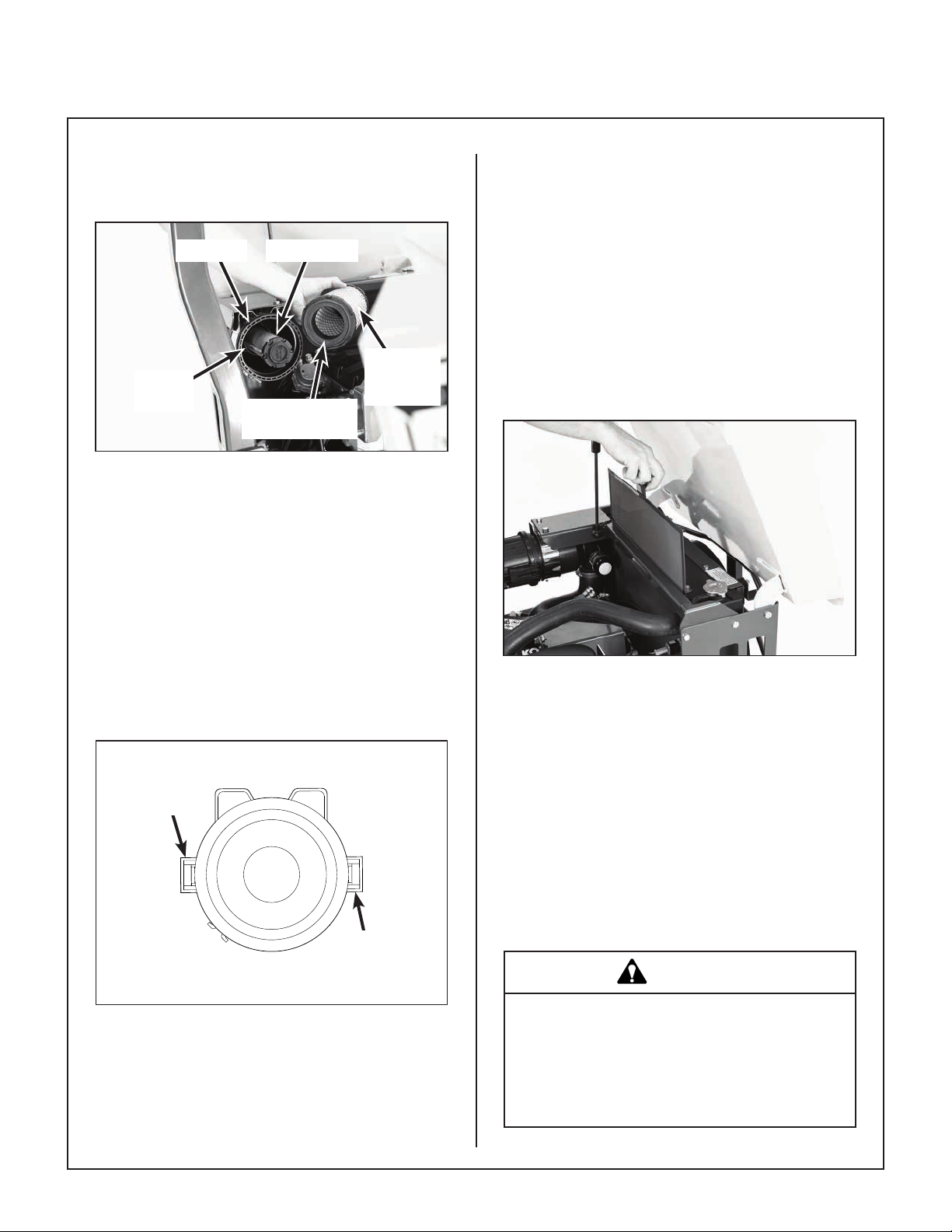
Maintenance Instructions CLEANING
8. Check the outside surface of the outlet tube for
smoothness and cleanness (this is the sealing
surface).
Safety FilterCanister
Primary
Outlet
Tube
Air Filter Element Replacement
9. Insert and seat the safety lter and primary lter
el ement carefully into the canister, applying
pres sure at the outer rim of the lter; not at the
exible center. Make sure the lter element is
completely in place before installing the cover.
Radial Sealing
Surface
Filter
Element
Engine Cooling System
Radiator Screen and Cooling Fins
To prevent the engine from overheating and possible
engine damage, clean grass clippings, chaff, and dirt
from the ne mesh radiator intake screen daily. In
certain mowing conditions (dry grass, leaves, tree
“cotton”, etc.), it may be necessary to check and
clean the screen several times during use to prevent
engine overheating.
1. With utility bed raised, lift to remove the screen.
To clean the screen, wash with soapy water or
blow out with compressed air.
NOTE: DO NOT use petroleum based lubri cants
on the sealing surfaces of the lter elements; use
tal cum powder or dry silicone lubricants if re-
quired for lter installation.
10. Install the Enginaire™ air cleaner cover. Latch
the two (2) cover latches.
Cover
Latch
Cover
Latch
Proper Orientation of Air Cleaner Cover
11. Check the air intake hose for cuts, nicks, cracks,
etc., and the hose clamps for tightness.
12. Reset the air lter restriction gauge (press button
on the end of the indicator).
Radiator Screen
2. Inspect the radiator cooling ns for material
lodged in this area which would restrict cooling
airow. Use pressurized air or water to clean.
DO NOT use any tool, like a screwdriver or
knife, to clean material out of the ns as this may
damage the cooling ns. DO NOT use cold
water on a hot radiator.
NOTE: Directing pressurized air or water from
the fan side of the radiator outward is recommended to dislodge material packed on the outside of the cooling ns. DO NOT use cold water
on a hot radiator.
WARNING
Radiator and engine parts can become extremely hot during operation. Wear gloves
and avoid touching hot parts while cleaning the radiator screen and cleaning debris
away from the engine and cooling system.
56
Page 61

Maintenance Instructions CLEANING
2802-5
<15°
1. 2.
Flushing Radiator and Changing Coolant
Change engine coolant every year. Drain the coolant from the engine and radiator:
1. Remove the radiator cap.
2. Open the drain plug on the bottom right corner
of the radiator. Also, drain the coolant recovery
tank.
3. Remove drain plug on RH side of the engine
block (below intake manifold). Also see Kohler
Owner’s Manual for location of the drain.
4. If there is any indication of deposits or scaling
inside the radiator, use a commercial scale remover and ush the cooling system thorough-
ly before adding fresh coolant.
Use a pre-mixed 50/50 solution of antifreeze (ethylene glycol) and distilled water to rell the cooling
system.
IMPORTANT: The solution of antifreeze and water
must be thoroughly pre-mixed before putting it in the
engine. Adding pure antifreeze into the radiator may
cause damage to the engine from overheating.
Tilt Bar
Unlock Deck Arms for Deck Tilt-Up
3. Fit tilt bar into the socket on front of deck housing and secure with hitch pin.
IMPORTANT: Maintain proper coolant level in the
radiator and coolant recovery tank. The coolant level
should be maintained between FULL and LOW
marks on the coolant recovery tank. Recheck the
coolant level after the rst time the engine has been
operated after lling the coolant system (it would be
normal to add a little coolant after initial operation).
Grass Buildup in Mower Deck Housing
DANGER
Before raising or removing the mower
deck for cleaning, stop the engine,
remove the ignition key, and disconnect
the electrical plug on the fuel shut-off
solenoid.
1. Remove the tilt bar from the stowed position on
the carrier frame.
2. Use the tilt bar to release the two (2) deck locking arms as shown in the Unlock Deck Arms
for Deck Tilt-Up illustration.
Use Hitch Pin to
Secure Tilt Bar.
Tilt Bar Installed
4. Remove footrest or, if equipped with adjustable
footrests, move the footrest to the full forward
locking position.
57
Page 62

Maintenance Instructions CLEANING
NOTE: If the buildup is severe, it may be easier
to clean the deck by removing the deck assembly from the tractor and standing the deck assembly on its “nose”.
NOTE: While some degree of material buildup
8746-2
in the mower deck housing can be tolerated, a
point is nally reached where cutting quality
deteriorates and clogging begins to occur
because of too much buildup on the bafing and
housing.
Full Forward/
Locked Position
Adjustable Footrest in Full Forward/Locked
Position for Deck Tilt-Up
5. Raise deck to tilt-up position using tilt bar and
secure in position by inserting the deck hook in
the tilt-up latch on the tractor body as shown in
the Deck Secured in TILT-UP Position photo.
Hitch Pin
Tilt-Up Hook and
Latch Connected
Tilt Bar
DANGER
Do not operate the mower with deck in tiltup position. Do not move the tractor with
the deck in the tilt-up position.
7. Lower the deck to the normal operating position
and rotate locking arms downward.
CAUTION
Do not operate mower with deck tilt-up
pivot joint UNLOCKED. Make sure locking
arms are in the LOCKED position and the
tilt-up joint is rigid (locked).
8. Remove tilt bar and stow on carrier frame.
9. Replace footrests to desired position.
Transaxle Housing
Tilt-Up
Latch
Deck Secured in TILT-UP Position
6. Clean grass buildup underneath the deck using
a pressure washer (and scraper if required).
58
Tilt-Up
Hook
Keeping the housing on the transaxles clean and
free of obstruction is essential to avoid overheat-
ing the transmission uid and shortening transmis-
sion life. The housing should be checked every 100
hours; and cleaned if necessary.
To clean the housing, use compressed air and/or a
pressure washer. Pay close attention to any oily dirt
buildup on the transaxle housings. This may be the
result of an oil leak. If an oil leak is noticed, contact
your local Walker dealer.
Page 63

Maintenance Instructions CLEANING
Cooling
Fins
Transaxle Housing and Cooling Fins
IMPORTANT: In case an oil leak develops on the
input shaft, the cooling fan blowing dusty air and oil
on the transmission will quickly cover the housing
and pack the cooling ns with oily dirt. If this condi-
tion occurs, contact your dealer immediately to avoid
overheating and dam aging the transaxle.
An additional procedure in maintaining transaxle
cooling is to inspect the cooling fans. Replace the
fan(s) if blades are missing or damaged.
Cooling
Fans
Transaxle Cooling Fans
59
Page 64

Maintenance Instructions CHECKING/SERVICING
CHECKING/SERVICING
DANGER
To prevent accidental starting of the engine when servicing or adjusting the machine, remove the key from the ignition
switch and disconnect the electrical plug
on the fuel shut-off solenoid.
Engine Cooling System
Coolant Level
WARNING
NEVER remove the radiator pressure cap
when the engine is hot — hot water could
spray and cause a burn if the cap is taken
off too soon.
IMPORTANT: The coolant solution of antifreeze and
distilled water must be thoroughly pre-mixed before
putting it in the engine (adding pure antifreeze into
the radiator may cause damage to the engine by
causing overheating).
Security of Air Cleaner System
NOTE: The following inspection is only an external
inspection and should be done without “disturbing” the ltration components.
On a daily basis, visually inspect the external condition of the complete air cleaner system. The following items should be inspected:
1. Check the Enginaire™ air cleaner canister for
damage. Make sure the cover is in place and
the cover latches are secure–do not run the engine without the air cleaner cover in place and
secure.
2. Inspect the air intake hose for cracks, nicks,
cuts, etc., and check the hose clamps for tightness.
3. Check to make sure the air lter restriction
gauge is in place and securely mounted on the
air cleaner housing.
Recovery Tank
Recovery (Overow) Tank
Check the coolant level in the coolant recovery tank
and maintain the coolant level between the FULL
and LOW marks on the recovery tank. When the
engine is cold, the coolant level should be at or slightly above the LOW mark on the recovery tank.
If the coolant level is low, remove the radiator cap and
ll to the overow port level and then ll the recovery
tank above the LOW mark. Use a pre-mixed 50/50
solution of antifreeze (ethylene glycol) and distilled
water to ll the cooling system.
Battery
NOTE: For initial battery service during setup, refer
to Battery Service in Assembly Instructions.
IMPORTANT: Make sure battery is securely mount-
ed in the frame. A loose battery may cause damage
to the case resulting in acid leakage and severe
damage to the machine. A hazard may be created
by damage to critical working parts and safety systems.
Electrolyte Level
The battery electrolyte level should be checked
after every 25 hours of operation. To check electrolyte level:
1. Remove battery cell ller caps.
2. Check the electrolyte level. If the level is below
the bottom of the vent well, ll with distilled water
to the bottom of the vent wells [1/4 to 1/2 in.
(6 to 13 mm) above the plates].
3. Replace ller caps.
IMPORTANT: DO NOT overll the battery. Electrolyte will overow through the vented caps onto parts
of the machine and WILL result in severe corrosion.
60
Page 65

Maintenance Instructions CHECKING/SERVICING
Cleaning the Terminals
If battery terminals are corroded, remove battery
from the mower. Using a wire brush, remove corrosion with a solution of one part baking soda and
four parts water. Rinse with clean water. Coat the
terminals with petroleum jelly or terminal protector
spray to retard further corrosion.
Charging the Battery
DANGER
BATTERIES PRODUCE EXPLOSIVE GASES
● Charge the battery in a well-ventilated
area, so that gases produced while charging can dissipate.
● Keep sparks, ames, and smoking ma
terials away from the battery at all times.
● Make sure the battery cap vents are open
(check manifold vent on each cap).
● Make sure the battery charger is un-
plugged before connecting or disconnecting cables to the battery.
Wheel Nuts Torque
Check the eight (8) Drive Tire mounting nuts. Every
100 hours they should each be torqued to
75 to 85 lb·ft (102 to 115 N·m).
Sharpen Mower Blades
Check mower blade(s) for straightness, sharpness, condition of the cutting edge, and balance
every 10 hours of operation (or more often when
mowing abrasive type grass or operating on sandy
soils). Replace blades if worn, bent, cracked, or
otherwise damaged (refer to REPLACING/REPAIRING the Mower Blades in this section). Use the
following procedure to check and sharpen blades:
NOTE: Keep blades sharp - cutting with dull blades
not only yields a poor mowing job but slows the cutting speed of the mower and causes extra wear on
the engine and blade drive by pulling hard.
1. Stop the engine, remove ignition key, and disconnect the electrical plug on the fuel shut-off
solenoid before raising the mower deck to service blades.
2. Raise the deck and secure it in the TILT-UP
posi tion (refer to Deck Secured in TILT-UP Po-
sition photo in CLEANING of Grass Buildup in
Mower Deck Housing in this section).
Check the battery charge by measuring the specic
gravity of electrolyte; if specic gravity is less than
1.225, the battery will need to be charged as follows:
1. Charge the battery at 15 amps for 10 minutes.
DO NOT exceed 20 amps maximum recom-
mended charging rate. Charge until specic
gravity is at least 1.250. Total charging time
should not exceed one (1) hour.
2. After charging the battery, use distilled water to
adjust the electrolyte level to the bottom of the
vent wells [1/4 to 1/2 in. (6 to 13 mm) above the
plates].
Tire Pressure
Inate tires to pressures shown below:
Deck Caster Wheel = 20 PSI (137 kPa)
Drive = 15 PSI (103 kPa)
Tailwheel = 20 PSI (137 kPa)
DANGER
NEVER operate cutter blades with the
deck in the raised position.
NOTE: PTO shaft must be disconnected
before checking blades for straightness.
3. Check the blades for straightness by marking
the blade tip position inside the deck housing,
and then rotating the opposite end of the blade
to the same position and comparing. If the difference in blade tip track is more than 1/8 in.
(3 mm), the blade is bent and should be re-
placed.
61
Page 66

Maintenance Instructions CHECKING/SERVICING
WARNING
DO NOT try to straighten a blade that is
bent. NEVER weld a broken or cracked
blade. ALWAYS replace with a new blade
to assure safety.
4. If the blade cutting edge is dull or nicked, it
should be sharpened. Remove blades for
sharpening by grasping the end of the blade using a rag or a thick, padded glove, while loosening and removing the bolt and washer that
mounts the blade.
5. Grind cutting edge at the same bevel as the
original. Sharpen only the top of the cutting
edge to maintain sharpness.
NOTE: Blades can be sharpened with an
electric blade sharpener, conventional electric
grinder, or a hand le.
CAUTION
7. Mount the blade with wing tips pointing up into
Drive Belts
Blade Balancer
Blade Balanced on Magnetic
Wall-Mounted Balancer
the housing. For gear driven decks reinstall
the blade, washer, lock washer, and nut. Tight-
en the nut to 60 lb·ft (81 N·m). For belt driven
decks reinstall the spacer (if applicable), blade,
washer, and bolt. Tighten the bolt to 70 lb·ft
(95 N·m).
ALWAYS wear eye protection and gloves
when sharpening a blade.
Sharpen at Original
30° Angle
30°
Do Not Grind or
Sharpen on Underside
Mower Blade Prole for Sharpening
6. Check blade balance by positioning the blade
horizontally on a blade balancer or use a nail
or shaft through the center hole. If either end of
the blade rotates downward, grind (remove)
metal on that end until the blade will balance.
The blade is properly balanced when neither
end drops. Balance of a blade is generally
main tained by removing an equal amount of
material from each end of the blade when
sharpening.
Intersection
Wear Area
Wing Tip
Raise the body and inspect the condition of the four
(4) drive belts after every 25 hours of operation–
engine/PTO drive (3), ground drive (1). Also, remove the belt cover on the mower deck and check
the blade drive belt. If the belts show signs of
cracking or deteriorating, the belts should be re-
placed. Refer to REPLACING/REPAIR ING the
Drive Belts in this section.
Fuel Lines and Clamps
Every year, inspect the fuel lines from the tanks to
engine for deterioration or damage. Also, inspect
the fuel line clamps for tightness. Good preventive maintenance calls for complete replacement of
fuel lines and clamps every two (2) years.
NOTE: This procedure is of special importance for
the diesel engine due to poor performance when air
is injected with the fuel.
Radiator Hoses and Clamps
Inspect the radiator hoses every 200 hours for deterioration or damage. Also check the tightness of the
hose clamps. Good preventive maintenance calls for
complete replacement of the radiator hoses and
clamps every two (2) years.
62
Page 67

Maintenance Instructions CHECKING/SERVICING
PTO U-Joints
The PTO U-joints should be inspected yearly for
looseness and wear. If either is noticed, the respective shaft or tube should be replaced. A worn U-joint
can cause vibration and extensive damage to the
PTO and the whole machine.
Blade Brake Action
WARNING
It is important to check and maintain
blade brake action for safe operation of
the ma chine.
Check the function of the cutter blade brake by
engaging the blade clutch (PTO), operating the
engine at full throttle, then disengaging the clutch
and measuring how quickly the blades stop. Watch
the rotation of the blade drive shaft as a visual indication that movement has stopped. If the brake is
working properly, all rotation will stop ve (5)
seconds after disengagement of the clutch. If the
brake system malfunctions -- blades do not stop in
ve (5) seconds -- adjust or repair the brake before
operating the mower. Refer to ADJUSTMENTS for
Clutch Disengagement/Brake Action, Step 2 - Blade
Brake Band Adjustment on page 78.
Safety Switch System
WARNING
If any of the following conditions occur during starting or operating, a safety interlock switch may be
malfunctioning. Contact your Walker dealer for troubleshooting and/or replacement.
● With or without an operator in the seat, the en-
gine starts with the Forward Speed Control (FSC)
and/or the PTO engaged.
● With an operator in the seat, the engine starts
but dies soon after the Forward Speed Control
(FSC) or PTO is engaged.
● Without an operator on the seat, the engine
continues to run with the Forward Speed Control
(FSC) and/or PTO engaged.
● With an operator in the seat, the Forward Speed
Control (FSC) and PTO disengaged and warning
horn sounding, but the starter will not engage.
Forward Speed Control Friction Lock
The FSC friction lock is designed to hold the selected forward travel speed when the steering le-
vers are moved and yet the friction is not too heavy
to make moving the FSC control difcult (too much
friction). The procedure for checking the FSC friction lock is as follows:
1. With the engine off, place the FSC in the full
FORWARD position and pull both steering levers back; the FSC lever should not move. If
the FSC lever moves back when the steering
levers are pulled back, the friction needs to be
increased.
It is important to check and maintain the
safety switch system for safe operation of
the machine.
There are three (3) safety interlock switches on the
tractor; Seat Switch, FSC Neutral-Park Switch, and
PTO Switch.
NOTE: There is a 1/2 second time delay function on
the seat switch to avoid engine power interruption
when driving over bumps.
2. With the steering levers held back, move the
FSC lever back from the FORWARD position.
With a proper amount of friction adjusted, the
FSC lever should move back with a slight
amount of resistance (friction). If the FSC lever
movement is “stiff”, the friction needs to be
decreased.
If the FSC friction lock needs to be adjusted, refer to
ADJUSTMENTS for Step 7 - Forward Speed Control Friction Adjustment in this section.
63
Page 68

Maintenance Instructions CHECKING/SERVICING
Transmission Control Setting
On a yearly interval or when an out-of-adjustment
condition is observed, check the transmission control for proper function as follows:
Neutral-Park
With the mower parked on level ground, start and
run the engine, rst at idle and then normal operat-
ing speeds. With the FSC in the NEUTRAL-PARK
position, there should be no movement of either
drive tire. If the tire(s) are “creeping” forward or reverse, refer to ADJUSTMENTS for the Neutral Func-
tion Adjustment - Step 3 in this section.
Straight Ground Tracking
Check for straight ground track by driving on a
smooth, level surface with hands off the steering levers. Set the FSC at different speeds and observe if
the mower moves in a straight line (use a cement
joint or other line on the ground for reference). If the
machine is drifting to the right or left, refer to
ADJUSTMENTS for Straight Tracking Adjust-
ment - Step 5 in this section.
64
Page 69

Maintenance Instructions REPLACING/REPAIRING
REPLACING/REPAIRING
DANGER
To prevent accidental starting of the
engine when replacing parts or repairing
the machine, remove the key from the
ignition switch and disconnect the
electrical plug on the fuel shut-off
solenoid.
IMPORTANT: ALWAYS use genuine factory re-
placement parts. Substitute parts CAN result in
product malfunction and possible injury to the operator and/or others.
Drive Belts
There are ve (5) individual drive belts on the ma-
chine:
● Engine/PTO Belt (Matched Set of 3)
● Ground Drive Belt
● Mower Blade Drive
The belts may be removed and replaced using the
procedures described on the following pages.
Ground
Drive Belt
Engine/PTO Belts
(Matched Set of 3)
Belt Locations (Engine Hidden for Clarity)
65
Page 70

Maintenance Instructions REPLACING/REPAIRING
Engine/PTO Belt
1. To remove the Engine/PTO belt:
a. Remove Upper LH Belt Guard and RH Belt
Guard by removing two (2) wing nuts.
Wing Nut
Upper LH
Guard
Fixed Idler
Pulley
Lower LH
Guard
Wire Lock Pin
PTO
Pulley
Clutch
Idler Pulley
PTO Guard
b. Remove two (2) wire lock pins and open
Lower LH Belt Guard and PTO Belt Guard.
c. Roll the belt off the pulley(s) and remove
the belt.
Wire Lock Pin
Right Hand
Guard
Wing Nut
PTO Belt(s)
(Matched Set)
PTO Belt (Belt Guards Open) (Engine Hidden for Clarity)
2. To replace the Engine/PTO belt:
a. Reverse the removal procedure to replace
the engine PTO belt.
Upper LH
Guard
Secure Wing
Nut
Lower LH
Guard
Wire Lock
Pin
Front View
Secure Wire Above Tab
b. Secure wire on lock pin above tab on lower
PTO guard.
Right Hand
Guard
Secure Wing
Nut
PTO Guard
66
PTO Belt (Belt Guards Closed) (Engine Hidden for Clarity)
Page 71

Maintenance Instructions REPLACING/REPAIRING
Ground Drive Belt
1. To remove the ground drive belt:
a. Remove belt tension by raising the spring-
loaded idler pulley with the deck tilt bar.
Deck Tilt
Bar
LH Transaxle
Ground Drive
Belt
Belt Tightener
Idler Pulley
Ground Drive Belt Assembly (Disengaged)
b. Slide belt off pulleys, then release the idler
pulley.
RH Transaxle
Transmission Belt
Tensioner Arm
Drive Pulley
Raise Idler Pulley to
Relax Belt
2. Reverse the procedure to install the ground
drive belt.
Deck Tilt
Bar
LH Transaxle
Ground Drive
Belt
Idler Pulley
Ground Drive Belt Assembly (Engaged)
RH Transaxle
Transmission Belt
Tensioner Arm
Drive Pulley
67
Page 72

Maintenance Instructions REPLACING/REPAIRING
Deck Drive Belt
1. To remove the deck drive belt:
a. Remove deck footrest and two (2) covers
over the RH and LH blade spindles.
b. Loosen belt tensioner stop bolt and turn in-
ward until retracted 1 in. (2.5 cm) from the
operating position.
c. Lock drive pulley so that it can not rotate.
* If deck is installed on tractor, the PTO
blade brake will prevent the drive pulley
from rotating.
* If deck is detached from tractor, use pry
bar or large screwdriver positioned
through the drive shaft U-joint to hold
shaft and prevent rotation.
d. From a position on the LH side of the deck,
grasp belt midsection and pull to compress
the belt tensioner springs and move the
tensioning pulley inward. The belt will then
slip off the LH spindle pulley and can be
completely removed.
2. Install the deck drive belt by reversing the removal procedure:
a. Route the belt as shown on the belt routing
decal (located on the deck housing). Leave
the belt loose at the LH spindle and then
install the belt by compressing the belt tensioner as noted above.
b. After the belt is in place, reset the belt ten-
sioner stop bolt by turning outward until
contacting the pulley bracket and then
making one (1) additional turn.
c. Reinstall spindle covers and footrest.
Spindle
Cover
Pulley Moves Inward to
Allow Belt to Slip Off
LH Blade Spindle
Belt Routing
Decal
2749-6
BELT TWIST
DR64 BELT P/N 2731-5
BELT TWIST
BELT ROUTING
Belt Tensioner
Stop Bolt
Footrest
8746-2
Spindle
Cover
Use Pry Bar or
Screwdriver Through
U-Joint to
Prevent Rotation
Grasp Belt Here and
Pull from LH Side to
Compress Springs on
Belt Tensioner
8600-28
68
Deck Drive Belt Replacement
Page 73
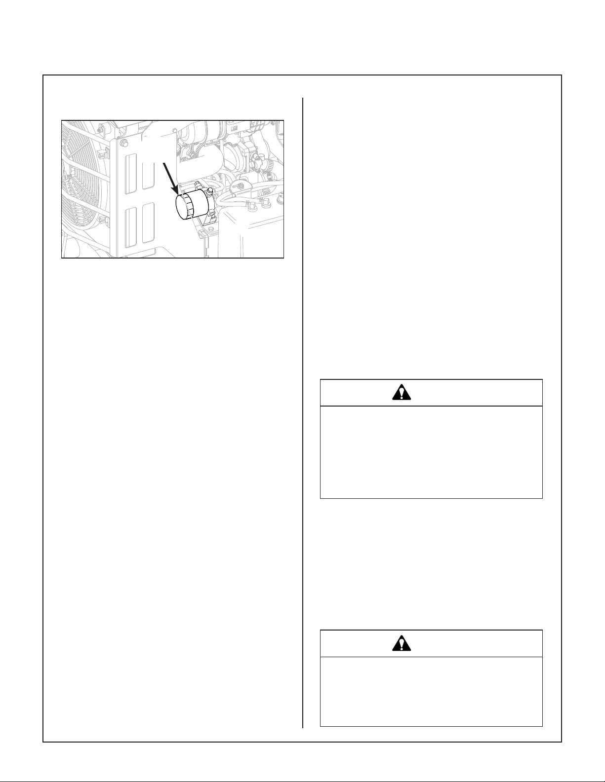
Maintenance Instructions REPLACING/REPAIRING
Fuel Filter
Fuel
Filter
Fuel Filter Location
IMPORTANT: Replace the fuel lter only in a clean
area where the connection surface will not be contaminated by dust and dirt.
The Kohler engine has a spin-on type fuel lter that
should be replaced every year using the following
procedure:
1. Turn the fuel tank selector valve to the OFF position.
2. Before removing the fuel lter, clean the area
around the lter to keep dirt and debris out of
the engine fuel system.
3. Remove the fuel lter and wipe off the lter
mounting surface on the engine.
4. Install the new fuel lter. Turn the lter until the
rubber gasket contacts the sealing surface,
then tighten the lter an additional 1/2 to 3/4
turn. Turn fuel tank selector valve ON to one of
the fuel tanks.
5. Before starting the engine, use the Fuel Pump
Priming procedure instruction in the Operating
Instructions to purge air out of the fuel system.
6. Start the engine and check for fuel leaks around
the lter/fuel hose connection used for priming.
Mower Blades
Mower blades are removed and remounted as described in the Sharpen Mower Blades instructions
(refer to CHECKING/SERVICING to Sharpen Mow-
er Blades in this section). During the course of
sharpening and inspecting mower blades, if there
are any of the following conditions of wear or
dam age, blades should be replaced for reasons
of safe ty and performance of the machine:
● An excessive amount of the at section of the
blade has been ground away (removed) when the
blade is sharpened. Replace the blade when less
than a 3/4 in. (19 mm) at section remains at the
blade tip.
● Examine ends of the blade carefully, especially
the intersection where the at section of the blade
turns up to form the “wing tip” (refer to Mower Blade
Pro le for Sharpening illustration in Sharpen
Mower Blades instructions). Since sand and abra-
sive ma terial can wear metal away in this area, the
blade should be replaced when metal thickness
has worn to 1/16 in. (1.6 mm) or less.
DANGER
When blades are operated over sandy
soil, and if blades are allowed to wear, a
“slot” may be worn into the wing tip of
blade. Eventually a piece of the blade
may break off creating a serious potential
for injury or damage.
● Check the blades for straightness by marking
blade tip position inside the deck housing and then
ro tating the opposite end of the blade to the same
po sition and comparing. If the difference in blade tip
track is more than 1/8 in. (3 mm), the blade is bent
and should be replaced.
● Inspect the blade surface, especially in formed
areas, for cracks. Replace the blade if any cracks
are found.
WARNING
DO NOT try to straighten a blade that is
bent. NEVER weld a broken or cracked
blade. ALWAYS replace with a new blade
to assure safety.
69
Page 74

Maintenance Instructions REPLACING/REPAIRING
Reinstall the blades following procedure from
Sharp en Mower Blades instructions. If blades are
re placed, always use Walker original equipment
blades to ensure safety and optimum performance.
The quality and performance of replacement
blades offered by other manufacturers cannot be
guar anteed, they could be dangerous.
CAUTION
ALWAYS use genuine factory replacement parts. Substitute parts CAN result
in prod uct malfunction and possible
injury to the operator.
70
Page 75

Maintenance Instructions ADJUSTMENTS
ADJUSTMENTS
Transmission Control
IMPORTANT: The proper adjustment of the tran-
saxle control stops is essential for efcient operation and life of the transaxle. These stops are properly ad justed at the factory and should only require
read justment if the transaxle or related control linkage is removed or changed.
NOTE: It would not be unusual for a new machine,
after the initial 5 or 10 hours of operation, to begin to
not travel straight (this is due to the break-in of the
tran saxles). To ne tune tracking, refer to Step 5 -
Straight Tracking Adjustment in this section.
Step 1 - Steering Lever Position Adjustment
NOTE: For proper operation, the steering levers
should be adjusted to sit evenly using the following
procedure.
1. Examine the steering levers to make sure they
are parallel front to back in relation to one an-
other. If they are not equal, adjust accordingly.
(The handles may or may not be even at this
point.)
NOTE: The LH steering lever is non-adjust-
able. This procedure will require adjustment of
the RH lever to make it even with the LH lever.
Levers should sit
parallel to each other
2. Adjust the position of the RH lever by turning the
stop bolt in the Speed Control Actuator in or out.
Turning the stop bolt in will make the RH lever
move back, and turning it out will make it move
forward. Tighten the locknut.
Stop
Bolt
Stop Bolt Location
Step 2 - Steering Handles Adjustment
1. An adjustment range of approximately 3 in.
(76.2 mm) is available on the steering handles the handles can be adjusted forward or aft
depending on the arm length of the operator.
The handles can be adjusted by loosening the
locknut at the pivot point and the locknut holding
the handle in position in the adjustment slide.
Adjust the handles into the most comfortable
position and tighten both locknuts.
Lever Alignment
Locknut
(Position)
Adjustment
Slide
Locknut
(Pivot Point)
Steering Handles Adjustment
71
Page 76

Maintenance Instructions ADJUSTMENTS
Step 3 - Neutral Function Adjustment
1. With the Forward Speed Control (FSC) in NEUTRAL-PARK, the lever should be straight up.
Adjust by loosening the jam nuts on the FSC
Rod and turn the rod to attain the straight up
position. Tighten the jam nuts.
Correct FSC Lever NEUTRAL-PARK Position
2. Securely block the tractor up so the drive tires
are off the ground.
3. Adjust the tracking adjustment nuts at the front
of both control rods so that 2 or 3 threads are
visible, then loosen the jam nuts on the ball
joints at the back of the control rods.
Control Rods
Control Arm
Tracking Adjustment Nuts
Transmission Control Rod and Arm Location
(Front Body Hidden for Clarity)
Tracking Adjustment Nut
(Adjusts Length of
Control Rod)
Maximum Speed
Adjustment Set Screw
72
Adjust Length of
Rod to Position
FSC Lever
FSC Lever Position Adjustment
Control Rod
Jam Nut
Ball Joint
Transmission
Control Arm
Tracking Adjustment Components
FWD
REV
Locating/Limit
Stud
Page 77

Maintenance Instructions ADJUSTMENTS
Step 4 - Full Forward Speed Adjustment
WARNING
1. Move the FSC to the full FORWARD speed po-
The following adjustments are made with
the engine running. Keep all body parts
and tools away from rotating and hot components, and secure all loose clothing.
4. With the body lowered and the FSC in NEUTRAL-PARK, start the engine. With the engine
at normal operating speed, check for movement
of the drive wheels.
5. Lift the body to access the steering adjustment
components.
NOTE: It may be necessary to tighten the FSC
friction adjustment if the transmissions are
moved out of neutral when the body is raised.
Refer to Step 7 - Forward Speed Control Friction
Adjustment later in this section for location of the
FSC friction adjustment nut.
6. Using a wrench on one tracking adjustment nut,
rotate the control rod clockwise just until the
wheel on that side begins to move forward.
Then, counting the turns required, rotate the
control rod counterclockwise just until the
wheel stops and then begins to move in re-
verse. Rotate the control rod back clockwise
half the number of turns required to make the
wheel go from moving forward to reverse. The
transmission is now centered in the neutral window. Tighten the jam nut on the ball joint and
repeat the same procedure on the other transmission.
sition.
2. Raise the body. The set screws in the left and
right Transmission Control Arms should not be
contacting the locating stud in the transaxle. If
they are, back the set screws out until they do
not touch.
T-Handle
Hex Wrench
Transmission
Control Arm
Maximum Speed Tracking Adjustment
(Shown with Parts Removed for Clarity)
Maximum
Speed Tracking
Adjustment
7. Turn off the engine, and then lower the drive
tires onto the ground.
73
Page 78

Maintenance Instructions ADJUSTMENTS
Step 5 - Straight Tracking Adjustment
1. Sit in the seat, start the engine, set throttle at full
speed, and with the FSC in the NEUTRAL-
PARK position check for movement of either
drive wheel (if either wheel moves backward or
forward, refer to the Step 3-Neutral Function Ad-
justment and readjust).
2. Check for straight ground tracking on a level
surface (with hands off the steering levers). Set
the FSC at several different speeds and observe
if the machine moves in a straight line (use cement joint or other line on ground for reference).
3. If travel is not straight, shorten the control rod on
the slow side by turning the tracking adjustment nut clockwise. If straight tracking and
neutral can not be achieved, turn the tracking
adjustment nut counterclockwise until neutral is
restored.
4. Lengthen the control rod of the faster side by
turning the tracking adjustment nut counterclockwise to match the slower side while maintaining the neutral position.
Step 6 - FSC Switch - Neutral Adjustment
1. Place the FSC lever in the NEUTRAL-PARK
position. Loosen mounting screws and adjust
the neutral switch up or down accordingly.
FSC Switch
FSC Neutral Switch Location
Switch Closed
in Neutral
FSC Switch
Actuator Arm
IMPORTANT: After tracking adjustments are
complete, conrm that there is at least one (1)
thread visible on both control rods past the
tracking adjustment nuts.
5. If the forward travel is straight throughout the
speed range, except at maximum speed - place
the FSC in full FORWARD, turn the set screw in
the Transmission Control Arm, of the faster
side, in until it contacts the limit stud. (Turning
the set screw in slows the wheel.) Turn the set
screw in an additional 1/8 turn. Recheck for
equal full for ward speed. Adjust this set screw
until equal full forward speed is achieved. Tighten the jam nut.
Deck Support
Arm (Ref)
Loosen Screws
NOTE: Adjust the switch downward for quicker
activation. (Switch Open)
FSC Switch Adjustment
(Side View Through Chassis)
CAUTION
Before testing the FSC Neutral Switch, disconnect the electrical plug on the fuel
shut-off solenoid and engage the parking
brake to prevent accidental starting and
inadvertent machine movement.
74
Page 79

Maintenance Instructions ADJUSTMENTS
2. Check operation of the FSC Neutral Switch by
placing the FSC lever in the full FORWARD
position. While holding the ignition switch in the
START position, slowly move the FSC lever
back towards the NEUTRAL-PARK position
until the starter motor engages. Stop moving
the lever and note the position of the FSC lever
where it passes through the slot in the body.
The FSC lever should be within 1/8 in. (3 mm)
of the NEUTRAL-PARK position. If this dis-
tance is greater than 1/8 in. (3 mm), the FSC
Neutral Switch needs to be adjusted downward
for quicker activation.
Step 7 - Forward Speed Control Friction Adjustment
FSC Friction
Adjustment Nut
FSC Friction Adjustment Nut
FSC Friction Adjustment Test
1. Place the FSC lever in the full FORWARD posi-
tion, and pull both steering levers fully back; the
FSC lever should not move. If the FSC lever
moves back the friction needs to be inc-
reased.
2. With the steering levers held back, move the
FSC lever back from the FORWARD position.
With a proper amount of friction adjusted, the
FSC le ver should move back with a slight
amount of re sistance (friction). If the FSC lever
movement is “stiff”, the friction needs to be de-
creased.
3. The FSC friction is increased or decreased by
tightening or loosening the friction adjustment nut. Loosen or tighten the nut and check
the control function until the conditions of both
steps 1 and 2 (above) are met.
75
Page 80
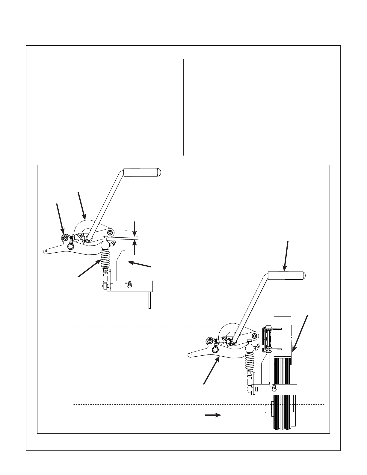
Maintenance Instructions ADJUSTMENTS
Blade Clutch (PTO)
Clutch Engagement/Belt Tension
The clutch engagement and PTO belt tension are
adjusted using the clutch actuator link. After installing
new PTO belts, after 10 hours and every 100 hours
thereafter, check and adjust for the clutch spring assembly bolt head dimension as shown in the PTO
Clutch Engaged illustration. If the clutch actuator
link or clutch spring assembly have been disassem-
bled, rst reset them to their factory preset lengths
(as shown in the PTO Clutch Disengaged illustration) and then proceed with adjustment as follows.
Clutch Actuator
Link
Ball Joint
1/4 in. to 5/16 in.
(6.35 mm to 7.94 mm)
Adjust the length of the clutch actuator link to
achieve a clutch spring assembly bolt head clearance of 1/4 in. to 5/16 in. (6.35 mm to 7.94 mm)
with the clutch engaged. To adjust length; remove
ball joint from clutch arm and shorten the clutch
actuator link to increase this measurement, or
lengthen the clutch actuator link to decrease this
measurement. If adjustments are needed more
frequently than every 100 hours to maintain dimensions, it may suggest problems with pulley wear or
belt misalignment.
Blade Clutch
Engaged
Clutch Spring Assembly
(Spring Compressed)
Clutch Engagement
Arm
Blade Clutch
Idler Pulley
Clutch Arm
Front of Mower
PTO Clutch Engaged
76
Page 81

Maintenance Instructions ADJUSTMENTS
Use the following procedures to check and adjust
clutch disengagement and brake action:
Step 1 - Idler Pulley Maximum Travel Adjustment
Loosen the brake band adjustment nut allowing
clutch pivot stop arm and stop bolt to make contact
6-1/4 in.*
(158.75 mm)
Clutch Actuator
Link
6 in.*
(152.4 mm)
Clutch Spring Assembly
(Spring Uncompressed)
*NOTE: Factory preset dimensions. Reset to
these dimensions prior to adjustment if components have been disassembled.
Knuckle Joint
2-1/8 in.*
(53.98 mm)
(refer to Blade Brake Band Adjustment illustration).
1. To check the pulley travel, rst engage the
clutch, then measure the distance the pulley
travels as the clutch is disengaged and the stop
arm contacts the stop bolt.
2. Adjust the pivot stop bolt to give 1-5/8 in. to
1-3/4 in. (41 mm to 44 mm) pulley travel from
“clutch engaged” to “clutch disengaged”.
NOTE: This adjustment will prevent excessive
pulley travel that can cause belts to develop too
much slack, causing possible belt derailment
upon disengagement.
1-5/8 in. to 1-3/4 in.
(41 mm to 44 mm)
CLUTCH DISENGAGED
CLUTCH ENGAGED
PTO Clutch Disengaged
Clutch Disengagement/Brake Action
WARNING
It is important to check and maintain blade
brake action for safe operation of the machine.
The declutched or disengaged position of the
blade clutch idler pulley is adjustable and is set to
give belt release without excessive slack and to
apply the blade brake. The blade brake is activated
by the brake band connected to the clutch engagement arm. The brake is designed to stop the blades
within ve (5) seconds after disengaging the clutch.
Idler Pulley
Clutch Pivot
Stop Bolt
Brake Engagement
Arm
Clutch Idler Pulley Travel
Clutch Pivot
Stop Arm
77
Page 82

Maintenance Instructions ADJUSTMENTS
Step 2 - Blade Brake Band Adjustment
After the maximum pulley travel is set, adjust the
working travel of the clutch idler pulley by adjusting
the brake band nut and make the following adjustment as needed:
Blade Brake
1. Adjust the blade brake band, using the adjustment nut until pulley travel is approximately
5/8 in. to 3/4 in. (16 mm to 19 mm) from engaged to disengaged.
NOTE: As blade brake band/drum wears, pulley travel will increase and it will be necessary
to adjust the blade brake band nut to maintain
these dimensions.
Band
CLUTCH DISENGAGED
CLUTCH ENGAGED
5/8 in. to 3/4 in.
(16 mm to 19 mm)
Clutch Idler Pulley Travel Adjustment
Blade Brake
Band Adjustment Nut
Blade Brake Band Adjustment
2. After adjustments are complete, check blade
brake action as described in CHECKING/SER-
VICING the Blade Brake Action in this section.
If blades do not stop within ve (5) seconds,
check the following:
a. Make sure clutch and brake linkage are
working freely (no binding).
b. Check the brake band lining for wear.
c. Check the brake drum on the pulley. If ex-
cessive wear is present, it will be necessary
to replace worn parts.
Chassis Mount
(Ref)
78
Page 83

LIMITED WARRANTY
FOR
WALKER MODEL H24d
RIDER MOWER
1. WHAT THIS WARRANTY COVERS, AND FOR HOW LONG:
Walker Manufacturing company will, at its option, repair or replace, without charge, any part covered by this warranty which
is found to be defective in material and/or workmanship within one (1) year* after date of sale to the original retail purchaser
unless the product is used for rental purposes, in which case this warranty is limited to ninety (90) days. At Walker’s request,
customer will make the defective part available for inspection by Walker and/or return the defective part to Walker, transportation charges prepaid. All parts and components of the Walker Mower are covered by this warranty except the following
components which are warranted separately by their respective manufacturers:
Kohler Engine
Hydro-Gear Transaxles
Battery
Tires
The available warranties covering these items are furnished with each mower. Walker does not assume any warranty obli-
gation, liability or modication for these items, which are covered exclusively by the stated warranty of the respective man-
ufacturers noted above.
* Extended warranties are offered for the following powertrain components:
• A three (3) year or 3000 hour (whichever comes rst) warranty is offered for Hydro-Gear ZT3400 Hydrostatic transaxle;
covers full cost of replacement up to 1000 hours of use, and after 1000 hours warranty coverage is prorated against
3000 hours.
2. WHAT THIS WARRANTY DOES NOT COVER:
A. This warranty does not cover defects caused by depreciation or damage caused by normal wear, accidents, improper
maintenance, improper use or abuse of the product, alterations, or failure to follow the instructions contained in the
Operator’s Manual for operation and maintenance.
B. The customer shall pay any charges for making service calls and/or for transporting the mower to and from the place
where the inspection and/or warranty work is performed.
3. HOW TO OBTAIN SERVICE UNDER THIS WARRANTY:
Warranty service can be arranged by contacting the dealer where you purchased the mower or by contacting Walker Manufacturing Company, 5925 East Harmony Road, Ft. Collins, CO 80528. Proof of the date of purchase may be required to
verify warranty coverage.
4. WARRANTY LIMITATION:
A. THERE IS NO OTHER EXPRESS WARRANTY. ANY WARRANTY THAT MAY BE IMPLIED FROM THIS PURCHASE
INCLUDING MERCHANTABILITY AND FITNESS FOR A PARTICULAR PURPOSE IS HEREBY LIMITED TO THE
DURATION OF THIS WARRANTY AND TO THE EXTENT PERMITTED BY LAW ANY AND ALL IMPLIED
WARRANTIES ARE EXCLUDED. Some states do not allow limitations on how long an implied warranty lasts, so the
above limitations may not apply to you.
B. WALKER WILL NOT BE LIABLE FOR ANY INCIDENTAL, CONSEQUENTIAL, OR SPECIAL DAMAGES AND/OR
EXPENSES IN CONNECTION WITH THE PURCHASE OR USE OF THE MOWER. Some states do not allow the
exclusion or limitation of incidental or consequential damages, so the above limitation(s) or exclusion(s) may not apply
to you.
C. Only the warranty expressed in this limited warranty shall apply and no dealer, distributor, or individual is authorized to
amend, modify, or extend this warranty in any way. Accordingly, additional statements such as dealer advertising or
presentations, whether oral or written, do not constitute warranties by Walker, and should not be relied upon.
D. This warranty gives you specic legal rights, and you may also have other rights which vary from state to state.
79
Page 84

WALKER MFG. CO. • 5925 E. HARMONY ROAD, FORT COLLINS, CO 80528 • (970) 221-5614
FORM NO. 060418 PRINTED IN USA www.walker.com ©2018 WALKER MFG. CO
 Loading...