

Page 1

H12: 42” Two-Stage Snowblower
H17: 50” Two-Stage Snowblower
Operator’s Manual
Safety, Assembly, Operating and Maintanence Instructions
H12 compatible with tractor models: MC, MD, MT
H17 compatible with tractor models: MH
Please Read and Save These Instructions
For Safety, Read All Assembly and Opeartion Instructions
Prior to Operating Attachment
H12 Beginning S/N: 21508289
H12 Eective Date: 03.25.15
H17 Beginning S/N: 21516633
H17 Eective Date: 09.22.15
P/N: 6670-14
Page 2

Foreword
Thank you. . .for purchasing a Walker Two-Stage Snowblower. Every eort has been made to provide you with
the most reliable machine on the market, and we are sure you will be among our many satisfied customers.
If for any reason this product does not perform to your expectations, please contact your local dealer. Every
customer is important to us. Your satisfaction is our goal.
Please. . .read this manual thoroughly! Before you operate your machine, please read this entire manual.
Some of the information is crucial for proper operation - it will help protect your investment and ensure that
the machine performs to your satisfaction. Some of the information is important to your safety, and must be
read and understood to help prevent possible injury to the operator or others. If anything in this manual is
confusing or hard to understand, please contact your local authorized dealer or call our service department,
at (970) 221-5614, for clarification before operating or servicing this machine.
This manual covers the H12, 42 in. Two-Stage Snowblower and the H17, 50 in. Two-Stage Snowblower.
All shields and guards must be in place for the proper and safe operation of this machine. Where they are
shown removed in this manual, it is for illustration purposes only. Do not operate this machine unless all
shields and guards are in place.
Specifications given are based on the latest information available at the time this manual was produced.
Walker Mfg. Co. is continually striving to improve the design and performance of its products. We reserve
the right to make changes in specifications and design without thereby incurring any obligation relative to
previously manufactured products.
i
Sincerely,
WALKER MANUFACTURING COMPANY
Bob Walker, President
Page 3

Table of Contents
GLOSSARY III
SPECIFICATIONS IV
Safety Instructions 1
BEFORE OPERATING 2
OPERATING 3
MAINTENANCE 4
Decals 6
Assembly 8
Installation 11
Operation 17
PREOPERATION CHECKLIST 17
SNOWBLOWER CONTROLS 18
SNOWBLOWER OPERATION 20
Removing and Storage 24
Maintenance 25
MAINTENANCE SCHEDULE CHART 25
LUBRICATION 25
REPLACING/REPAIRING PARTS 28
ADJUSTMENTS 31
WARRANTY 44
H12
• The following are required for mounting the H12 42 in. Two-Stage Snowblower
- MC, MT, MD Tractors: H10 Implement Mount Hitch
- MH Tractors: H19 Implement Mount Hitch
H17
• The following are required for mounting the H17 50 in. Two-Stage Snowblower
- MC, MT, MD Tractors: H10 Implement Mount Hitch
- MH Tractors: H19 Implement Mount Hitch
OPTIONAL UPGRADES
P/N 6623-4 Snowblower Chute Control Kit: For use on MH with A33 Hard Cab.
HIGHLIGHTED INFORMATION
Walker Manufacturing recommends that any service requiring special training or tools be performed by an
authorized Walker Mower Dealer. There are several general practices to be aware of in the area of safety.
Most accidents associated with the operation or maintenance of a Walker product are caused by disregarding
basic safety precautions or specific warnings. Such accidents, in most cases, can be prevented by being
aware of the dangers present. Information of special importance has been highlighted in bold type.
Information of special importance has been highlighted in bold type in this manual. Refer to Safety Instructions
for the meanings of DANGER, WARNING, CAUTION, IMPORTANT, and NOTE.
ii
Page 4

Safety Instructions
Pay particular attention to any information labeled DANGER, WARNING, CAUTION, IMPORTANT, and
NOTE in this manual.
When you see the Safety Alert Symbol (
comply with safety instructions may result in personal injury.
The seriousness or degree of importance of each type of information is defined as follows:
An IMMEDIATE hazard that WILL result in severe personal injury or
DEATH, if warning is ignored and proper safety precautions are not
taken.
A POTENTIAL hazard that COULD result in severe personal injury or
DEATH, if warning is ignored and proper safety precautions are not
taken.
Possible hazards or unsafe practices that MAY result in MODERATE
personal injury or property damage, or machine damage, if warning
is ignored and proper safety precautions are not taken.
!
), read, understand, and follow the instructions. Failure to
DANGER
WARNING
CAUTION
!
!
!
IMPORTANT: Identifies mechanical information demanding special
attention, since it deals with the possibility of damaging a part or parts
of the machine.
NOTE: Identifies information worthy of special attention.
Walker Manufacturing cannot predict every potentially dangerous situation. Therefore, items labeled as
such in this manual do not cover all conceivable situations. Any person using procedures, tools, or control
techniques not recommended by Walker Manufacturing must take full responsibility for safety. The Walker
tractor and implement attachments have been designed with many safety features to protect the operator
from personal harm or injury. However, it is necessary for the operator to use safe operating procedures
at all times. Failure to follow safety instructions contained in this manual may result in personal injury or
damage to equipment or property. If you have any questions concerning setup, operation, maintenance,
or safety, please contact your authorized Walker Mower dealer or call Walker Manufacturing Company at
(970) 221-5614.
1
Page 5

BEFORE OPERATING
1. Read and understand the contents of this Operator’s Manual before operating the machine. Become
thoroughly familiar with all controls and how to stop the machine and disengage the controls quickly.
Replacement Operator’s Manuals are available by sending the model and serial number to:
Walker Manufacturing Company
5925 E. Harmony Road
Fort Collins, CO. 80528
2. Never allow children to operate or give rides on the machine. Do not allow adults to operate without
proper instruction.
3. Do not allow anyone other than the operator on the machine.
4. Keep everyone, especially children and pets, a safe distance away from the area being cleaned. Do not
operate with bystanders in the area.
5. Do not operate the machine wearing sneakers, tennis shoes, or similar lightweight footwear. Wear
substantial protective footwear that will improve footing on slippery surfaces.
6. Snow or leaves can sometimes hide objects that might clog the snowblower, or otherwise cause damage.
Clear the area of doormats, sleds, boards, wires and other debris.
7. Do not wear loose fitting clothing that could get caught in moving parts. Always wear adequate protective
clothing including long pants. Wearing safety glasses, safety shoes, and a helmet is advisable and required
by some local ordinances and insurance regulations.
8. Prolonged exposure to loud noise can cause impairment or loss of hearing. Operator hearing protection
is recommended. Wear a suitable hearing protective device such as earmus or earplugs.
9. Keep all protective shields and safety devices in place. If a protective shield, safety device, or decal is
damaged, unusable, or missing, repair or replace it before operating the machine.
10. Be sure any interlock switches are functioning correctly so the engine cannot be started unless the
Forward Speed Control (FSC) lever is in the NEUTRAL position and the PTO clutch is in the DISENGAGED
position. Also, the engine should stop if the operator lifts o the seat with the PTO clutch in the ENGAGED
position.
11. Never attempt to make any adjustments while the engine is running, except where specifically instructed
to do so.
2
Page 6

12. Handle gasoline or diesel fuel with care. Gasoline is highly flammable and its vapors are explosive:
a. Use an approved fuel container.
b. Never add fuel to a running engine or hot engine (allow hot engine to cool several minutes).
c. Keep matches, cigarettes, cigars, pipes, open flames, or sparks away from the fuel tank and fuel
container.
d. Always fill the fuel tank outdoors using care. Fill to about one inch from the top of the tank.
Use a funnel or spout to prevent spilling.
e. Replace the machine fuel cap and container cap securely and clean up any spilled fuel before
starting the engine.
OPERATING
NOTE: Refer to your tractor Operator’s Manual for safety instructions for operating
the tractor.
1. Operate the machine only in daylight or in good artificial light with good visibility of areas being cleaned.
2. Sit on the seat when starting the engine and operating the machine. Keep feet on footrests at all times
when the tractor is moving and/or the implement is operating.
3. An inexperienced operator should learn to steer (maneuver) the tractor with a slow engine speed
before attempting any operating. Be aware that, with the front mounted implement configuration, the
back of the machine swings to the outside during turns.
4. Remember, for an emergency stop, the forward motion of the tractor can always be stopped by pulling
the Forward Speed Control (FSC) into the NEUTRAL-PARK position.
5. Disengage the PTO clutch and put the FSC in the NEUTRAL-PARK position before starting the engine (an
ignition interlock switch normally prevents starting of the tractor if these controls are in the OPERATING
position).
6. Do not run the engine in a confined area without adequate ventilation. Exhaust fumes are hazardous
and can be deadly.
7. Do not carry passengers - maximum seating capacity is one (1) person.
8. Make sure the auger is clear of snow, ice, or debris before engaging the PTO clutch.
9. Be careful never to throw snow towards people or cars, and never allow anyone in front of the implement.
10. Watch out for hazards hidden under snow that could enter the chute while operating.
11. Avoid sudden starts or stops. Before backing the machine up, look to the rear to be sure no one is behind
the machine. Watch carefully for trac when crossing or working near roadways.
12. Disengage the PTO clutch when transporting the machine.
13. Do not operate across the face of slopes. Use extreme caution when changing direction on slopes. Do
not attempt to clear steep slopes.
3
Page 7

14. Never adjust gauge wheels or skid shoes with the engine running. Before adjusting height or servicing,
disengage the PTO clutch, stop the engine, and remove the ignition key. Wait for all movement to stop
before getting o the seat.
NOTE: The PTO brake should stop drive line rotation within five (5) seconds of
disengaging the PTO clutch. If the brake is not functioning properly, have it repaired
by an authorized dealer immediately.
15. Do not operate the snowblower with the blower spout assembly removed.
16. If snowblower clogs:
a. Disengage the PTO clutch, stop the engine, and remove the ignition key before leaving the
seat.
b. Look to make sure PTO shaft and auger movement has stopped before trying to unclog the
snowblower.
c. Disconnect the fuel solenoid wire [diesel engines] or spark plug wire(s) [gasoline engines].
d. DO NOT use hands or feet to unclog the snowblower - use a stick or similar tool.
17. If the implement strikes a solid object or the machine begins to vibrate abnormally, immediately
disengage the PTO clutch, stop the machine, and remove the ignition key. Wait for all moving parts to
stop. Disconnect the fuel solenoid wire [diesel engines] or the spark plug wire(s) [gasoline engines] to
prevent accidental starting. Thoroughly inspect the implement and repair any damage before restarting
the engine and operating the machine. Make sure implement components are in good condition and all
bolts are tight.
18. Do not touch the engine or muer while the engine is running or immediately after stopping the engine.
These areas may be hot enough to cause serious burns.
19. When leaving the machine unattended, disengage the PTO clutch, stop the engine, and remove the
ignition key.
MAINTENANCE
NOTE: Refer to your tractor Operator’s Manual for proper tractor maintenance
procedures.
1. To prevent accidental starting of the engine when servicing or adjusting the machine, remove the key
from the ignition switch and disconnect the fuel solenoid wire [diesel engines] or the spark plug wire(s)
[gasoline engines].
2. To reduce fire hazards, keep the engine free of grass, leaves, excessive grease, and dirt.
3. Keep all nuts, bolts, and screws tight to ensure the machine is in a safe, working condition.
4. Perform only maintenance instructions described in this manual. Unauthorized maintenance operations
or machine modifications may result in unsafe operating conditions.
4
Page 8

5. If the engine must be running to perform a maintenance adjustment, keep hands, feet and clothing away
from moving parts. Do not wear jewelry or loose clothing.
6. Always use proper engine service manuals when working on the engine. Unauthorized maintenance
operations or modifications to the engine may result in unsafe operating conditions.
7. Altering the machine in any manner which adversely aects its operation, performance, durability or use
will VOID the warranty and may cause hazardous conditions.
8. Never attempt to disconnect any safety devices or defeat the purpose of these safety devices.
9. Do not change the engine governor settings or overspeed the engine. The governor has been factory-set
for maximum-safe engine operating speed.
10. Use genuine factory replacement parts. Substitute parts may result in product malfunction and possible
injury to the operator and/or others.
IMPORTANT: Keep all applicable manuals immediately accessible to anyone
who may operate or service this machine.
5
Page 9

GLOSSARY
There are many terms that are either unique to this equipment or that are used as acronyms. The following
terms and their definitions will help while using this manual.
FORWARD SPEED CONTROL FSC controls the maximum forward speed of the tractor; functioning as
a cruise control.
IMPLEMENT refers to the two-stage snowblower used with the tractor with an implement hitch installed.
LEFT HAND LH refers to the left-hand side of the machine when the operator is seated facing forward
in the tractor seat.
MACHINE consists of the implement installed on the tractor, functioning as a single unit.
POWER TAKEOFF PTO transmits engine power to run the two-stage snowblower.
RIGHT HAND RH refers to the right-hand side of the machine when the operator is seated facing forward
in the tractor seat.
TRACTOR is the prime mover, including the engine, drivetrain, operator seat, and controls to operate the
implement.
IDENTIFYING NUMBER LOCATIONS
The two-stage snowblower serial number is axed to the RH side of the snowblower head frame. Model
and serial numbers are helpful when obtaining replacement parts and maintenance assistance. For ready
reference, please record these numbers in the space provided.
Two-Stage Snowblower Model No.
Two-Stage Snowblower Serial No.
Date of Purchase
Fill In By Purchaser
Serial Number
Two-Stage Snowblower Serial Number Location
iii
(Rear View and RH View)
Page 10

UNIT DESCRIPTION
The 42 in. (107 cm) two-stage snowblower throws snow up to 40 ft (12 m). It is raised and lowered
automatically with the lift control switch. The blower spout is controlled with a simple position control
handle, or the Snowblower Chute Control Kit (P/N 6623-4) for use with model H only. The snowblower is
powered by the tractor PTO through the PTO shaft, snowblower drive shaft, and gearbox. Tire chains and a
soft cab are available as optional equipment for models C, T, and D. Tire chains and a hard cab are available
as optional equipment for model H.
SPECIFICATIONS
Two-Stage Snowblower H12 H17
Height Without Chute in. (cm) 20-1/2 (52) 20 (51)
Width in. (cm) 42-1/4 (107) 50 (127)
Length With Female Hitch in. (cm) 30 (76) 30 (76)
Overall Length Installed on Tractor in. (cm)* 97-1/2 (248) 105 (267)
Cutting Height in. (cm) 19 (48) 19 (48)
Weight With Female Hitch lb (kg) 180 (82) 193 (88)
Throwing Distance ft (m) 40 (12) 40 (12)
Lift 12 Volt DC Electric Linear Actuator, Operated by Toggle
Switch Mounted on FSC Lever
Hitch System Patented Quick Hitch System
Type Blower Two-Stage with 12-7/8 in. (33 cm) Diameter Auger and
15-3/4 in. (40 cm) Diameter, 3-Blade Impeller, Clockwise
Rotation
Snowblower PTO Drive Quick Disconnect Splined PTO Shaft with Two (2) High-
Speed U-Joints
Impeller Drive Chain, #40
Driving Sprocket: H40C11
Driven Sprocket: H40B32
Auger Drive Worm Gearbox, 5:1 Ratio, SAE EP 90W Gear Oil
Discharge Angle Adjustment Chute Direction Rotates 228o by Crank, Adjustable Spout
Deflector, Adjustable from Operator Seat, Up to 40 ft.
(12 m) Discharge Distance
Body Construction Frame Thickness: 14 Gauge Steel
Side Thickness: 11 Gauge Steel
Impeller Housing Thickness: 14 Gauge Steel
Depth Guide Two Adjustable, Replaceable Skid Shoes, Adjustable from
* H12 with model MT, H17 with model MH
NOTE: The manufacturer reserves the right to make changes in specifications shown herein at any time
without notice or obligation.
1/4 to 3/4 in. (6 to 19 cm)
iv
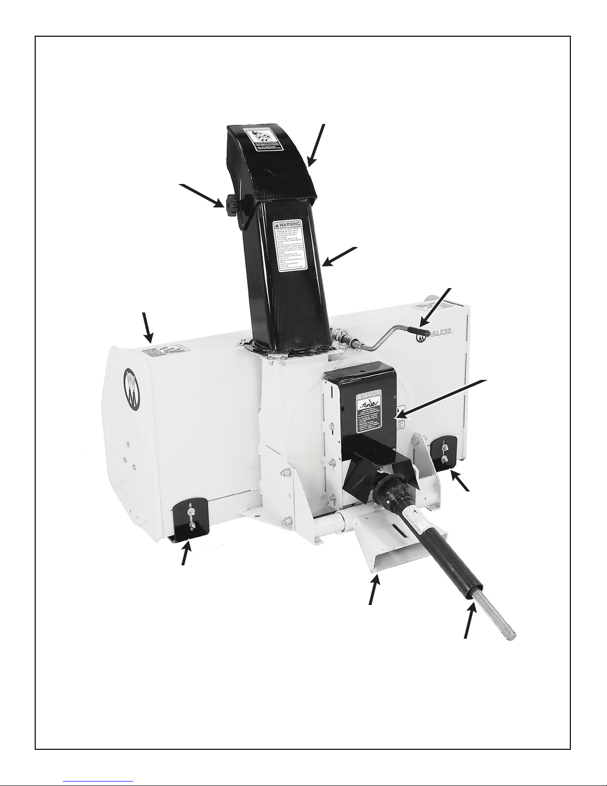
Page 11

Deflector Position
Control Knob
Deflector
Chute Rotation
Handle
Fan
Chute
Hand Guard
Gearbox Support
Bracket
Auger
Frame
Two-Stage Snowblower Front View and Right Side View (Not Installed)
v
Gearbox
Auger
Page 12
Deflector Position
Control Knob
Snowblower
Housing
Deflector
Chute
Chute Rotation
Handle
Reduction
Box Cover
Skid Shoe
Two-Stage Snowblower Rear View (Not Installed)
Skid Shoe
Female Quick Hitch
PTO Drive Shaft
vi
Page 13
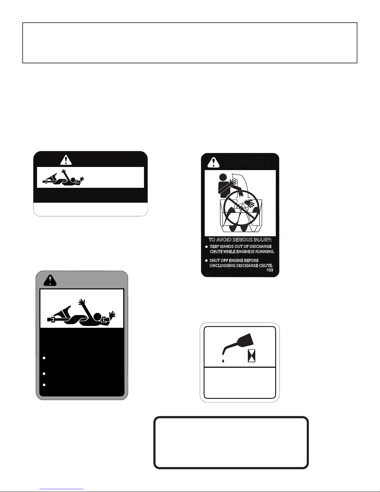
Decals
SAFETY, CONTROL, AND INSTRUCTION DECALS
Safety, Control, and Instruction Decals are installed on the machine; if any are missing, illegible, or
damaged, a replacement should be ordered and installed before putting the machine into operation.
The Decal Part Number is listed below.
Safety Decal: Rotating Driveline
Location: PTO Shield
Part Number: 7822
DANGER
ROTATING DRIVELINE
CONTACT CAN CAUSE DEATH
KEEP AWAY!
ALL DRIVELINE, TRACTOR AND EQUIPMENT SHIELDS IN PLACE.
DRIVELINE SHIELDS THAT TURN FREELY ON DRIVELINE.
IMPORTANT
position and the implement in the lowered position. Open the PTO shield ONLY for connecting
or disconnecting driveline.
– DO NOT OPERATE WITHOUT –
DRIVELINES SECURELY ATTACHED AT BOTH ENDS.
When raising tractor body, the PTO shield must be closed or in the down
7822
Safety Decal: Rotating Driveline
Location: PTO Guard
Part Number: 657763 (RAD)
DANGER
Safety Decal: Keep Hands Out
Location: Discharge Chute
Part Number: 657761 (RAD)
DANGER
TO AVOID SERIOUS INJURY:
KEEP HANDS OUT OF DISCHARGE
CHUTE WHILE ENGINE IS RUNNING.
SHUT OFF ENGINE BEFORE
UNCLOGGING DISCHARGE CHUTE.
Lubrication Decal: Lubricate Chain
Location: Snowblower housing
133
ROTATING DRIVELINE
CONTACT CAN CAUSE DEATH.
KEEP PEOPLE AND CLOTHING AWAY.
DO NOT OPERATE WITHOUT:
ALL DRIVELINE, TRACTOR
AND EQUIPMENT SHIELDS
IN PLACE
DRIVELINE SECURELY
ATTACHED AT BOTH ENDS
DRIVELINE SHIELD TURNING
FREELY ON DRIVELINE.
135
Safety Decal: Rotating Driveline
Location: Above Serial Numer Plate
Part Number: 655683 (RAD)
Part Number: 657804 (RAD)
4
STOP ENGINE BEFORE LUBRICATING
LUBRICATE CHAIN EVERY
4 HOURS WITH CHAIN
SAW CHAIN LUBRICATE
IMPORTANT
BEFORE USING:
• OIL LEVEL MUST BE CHECKED
• FILL WITH SAE 80W90. “AGMA 5 EP”
EXTREME PRESSURE OIL OR EQUIVALENT.
• READ INSTRUCTIONS MANUAL.
137
14
6
Page 14

Safety Decal: Safety Procedures
Safety Decal: Rotating Auger
Location: Discharge Chute
Part Number: 660988 (RAD)
WARNING
FAILURE TO FOLLOW SAFE OPERATING
PROCEDURES MAY RESULT IN INJURY.
FOR SAFE OPERATION FOLLOW ALL OPERATING
INSTRUCTIONS AND SAFETY PRECAUTIONS IN
OPERATOR’S MANUAL.
EYE PROTECTION MUST BE WORN AT ALL TIMES.
KEEP HANDS, FEET AND CLOTHING AWAY FROM POWER
DRIVEN PART.
STOP ENGINE BEFORE LEAVING OPERATOR POSITION.
WAIT FOR ALL MOVEMENTS TO STOP BEFORE STARTING
TO ADJUST, LUBRICATE, CLEAN OR UNCLOG THE MACHINE.
KEEP THE AREA OF OPERATION CLEAR OF ALL PERSONS
AND ANIMALS.
KEEP ALL GUARDS AND SHIELDS IN PLACE.
NEVER DIRECT DISCHARGE TOWARDS BYSTANDERS,
BUILDING, CARS ETC.
ALWAYS USE A DUST MASK WHEN WORKING IN DUSTY
CONDITIONS.
KEEP PLASTIC AWAY FROM INTENSE HEAT
AND OPEN FLAME.
NEVER ALLOW PASSENGERS ON THE ATTACHMENT.
Important Decal: Use Shear Bolts
229
Location: Snowblower Housing
Part Number: 657762 (RAD)
DANGER
Avoid Injury From
Rotating Auger:
Keep hands,feet and
clothing away.
Shut off engine before
servicing.
Decal: Walker Decal
134
Location: Inside Housing Behind Auger
Part Number: 657346 (RAD)
IMPORTANT
USE SPECIAL AUGER
SHEAR BOLT ONLY.
#BER657295
ONE END UP
USE SPECIAL FAN
SHEAR BOLT ONLY.
#BER656053
ONE END DOWN
Location: Snowblower Housing
Part Number: 5800-9
112
Decal: Walker Decal
Location: Snowblower Housing
Part Number: 5809-2
7
Page 15

Assembly
1. Remove the rear shaft support from the chute base lip and discard the existing bolt. Refer to Figure 1.2 to
locate the rear shaft support.
2. Place the plastic anti-friction insert over the chute base as shown in Figure 1.1. Only one position provides
a perfect fit.
Nipple (Facing Up)
Rear
Front
Figure 1.1: Install Plastic Insert
3. Insert the 1-5/16 in. (33 mm) plastic bushing into the tube weldment, then insert the 1-11/16 in. (43 mm)
plastic bushing into the rear shaft support and place over the shaft on the rotation worm as shown in
Figure 1.2.
4. Install the rotation worm assembly into the tube weldment with the rear shaft support plate on the
underside of the chute base lip as shown in Figure 1.2.
1-5/16 in. Bushing
Tube Weldment
1-11/16 in.
Bushing
Rotation Worm
Rear Shaft
Support
Figure 1.2: Install Rotation Worm Assembly
5. Install the chute over the plastic insert and secure with four retaining plates (as shown in Figure 1.3), using
two (2) 1/4 x 1/2 in. bolts, lock washers, and nuts in each of the three (3) standard retaining plates, and two
(2) 1/4 x 3/4 in. bolts, lock washers and nuts in the rear right retaining plate which also secures the rear
shaft support. Tighten all bolts to 10 ft-lb (13.6 N•m).
8
Page 16

6. Insert two (2) 5/16 x 1 in. carriage bolts through each of the skid shoes from inside the bend. Place a flat
washer, lock washer, and nut loosely on each bolt and place the bolt heads through the round holes in the
outer ends of the bottom angle of the snowblower body as shown in Figure 1.4. Adjust the skid shoes to
allow the required clearance under the cutting edge. Slide the square shank portion of the bolt head into
the slot and tighten the nuts securely. Refer to ADJUSTMENTS - Skid Shoes in Maintenance section.
Chute
Snowblower
Housing
Retaining Plates
Carriage Bolts
Skid Shoe
Figure 1.3: Install Chute and Retaining Plates
7. Install the hand guard on the chute, with the top section inside the chute and the bottom section outside
the chute base ring. Place two (2) 1/4 x 3/4 in. bolts through the chute and the hand guard. Secure bolts
with a flat washer, lock washer, and nut. Position each bolt with the head on the outside of the chute and
the nut on the inside, and torque bolts to 10 ft-lbs (13.6 N•m).
Hand Guard
Figure 1.4: Install Skid Shoes
Figure 1.5: Installing Hand Guard on Chute
8. Thoroughly clean the drive shaft yoke and install a 1/4 x 1/4 x 1-1/4 in. key in the drive shaft keyway as
shown in Figure 1.6.
9
Page 17

Drive Shaft
1/4 x 1/4 x 1-1/4 Key
Set Screw
PTO Drive Shaft Yoke
Figure 1.6: Attach PTO Drive Shaft Yoke to Snowblower Drive Shaft
9. Slide the drive shaft yoke over the drive shaft.
10. Secure the yoke to the drive shaft with a 1/4 x 2-1/2 in. bolt and nylon locknut. Tighten the nut and the
3/8 x 3/8 in. allen set screw securely over the key in the yoke.
11. Install one (1) 5/16-18 x 5/8 in. hex bolt on each side of the PTO guard, and tighten securely as shown in
Figure 1.7.
PTO Guard
Guard Mount
Bolt
Figure 1.7: Install PTO Guard
10
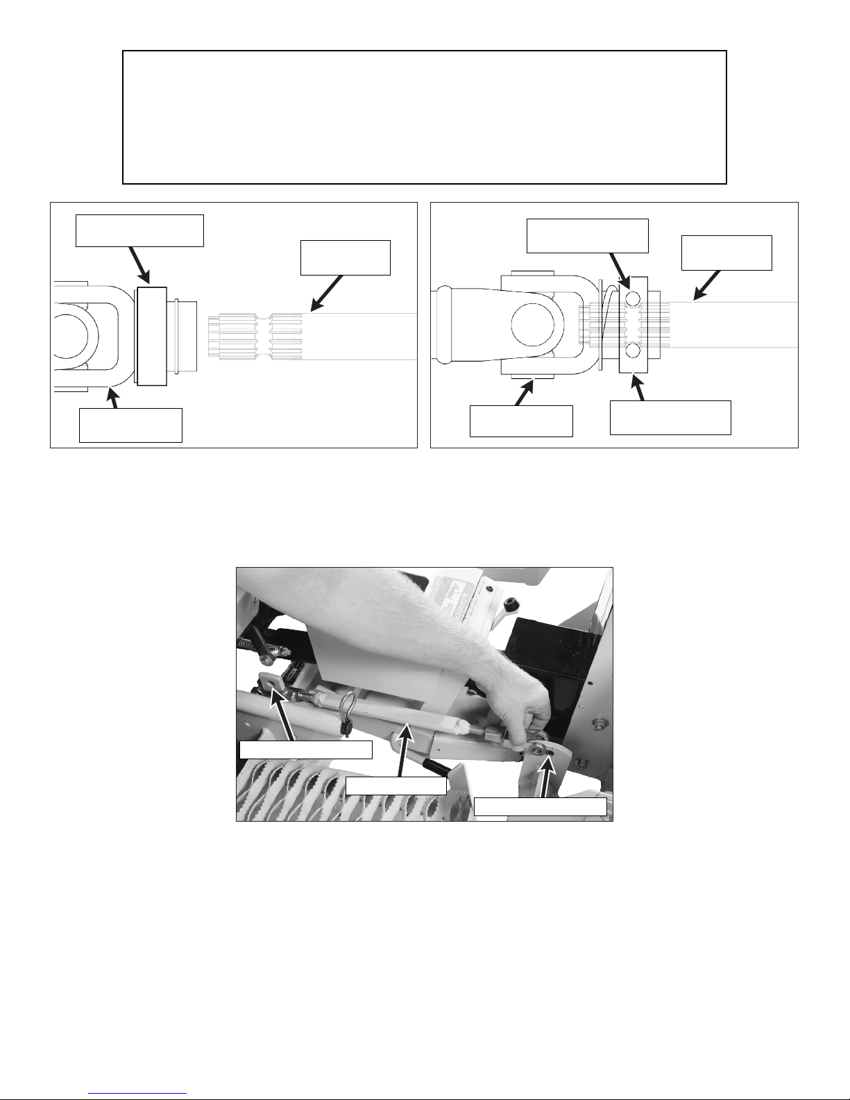
Page 18

Installation
1. Grease the drive shaft spline sliding surfaces and slide the PTO coupler (tractor half) onto the shaft as
shown in Figure 2.1.
Figure 2.1: Install PTO Coupler on Drive Shaft
2. Retract the spring-loaded quick disconnect ring on the PTO Coupler and insert the Coupler Installation
Tool (provided in Owner’s Packet) as shown in the Figure 2.2.
NOTE: The Coupler Installation Tool is provided for convenience,
but is not required for installation.
Coupler
Installation Tool
PTO Coupler
Tube
Retract Spring-Loaded
Quick Disconnect Ring
Figure 2.2: PTO Coupler Installation Tool
11
Page 19

3. Insert the male quick hitch section of the implement hitch into the female socket of the snowblower as
shown in Figure 2.3 and Figure 2.4.
Female Socket
Male Hitch
Figure 2.3: Male To Female Hitch Connection
4. Lock the snowblower in place with the locking lever on the implement hitch: All implements must be
locked in place on the implement hitch before beginning any operation.
H10: Locking/Removing Implements
• Locking: Rotate the hitch lock lever fully forward to the LOCKED position as in Figure 2.5, and
secure the hitch latch with the linch pin.
• Removing: Remove the linch pin from the latch and move the hitch lock lever backward to the
UNLOCKED position as in Figure 2.6.
Linch Pin
Locking Lever
LOCKED
Figure 2.4: Hitch Connected To Snowblower
Locking Lever
UNLOCKED
Figure 2.5: Hitch Lock Lever in “LOCKED” Position Figure 2.6: Hitch Lock Lever in “UNLOCKED” Position
(View From Right Side of Tractor) (View From Right Side of Tractor)
12
Page 20

H19: Locking/Removing Implements
• Locking: Rotate the hitch lock lever fully backward to the LOCKED position as in Figure 2.7.
• Removing: Move the hitch lock lever forward to the UNLOCKED position as in Figure 2.8.
Locking Lever
LOCKED
Locking Lever
UNLOCKED
Figure 2.7: H19 Locking Lever in “LOCKED” Position Figure 2.8: H19 Locking Lever in “UNLOCKED” Position
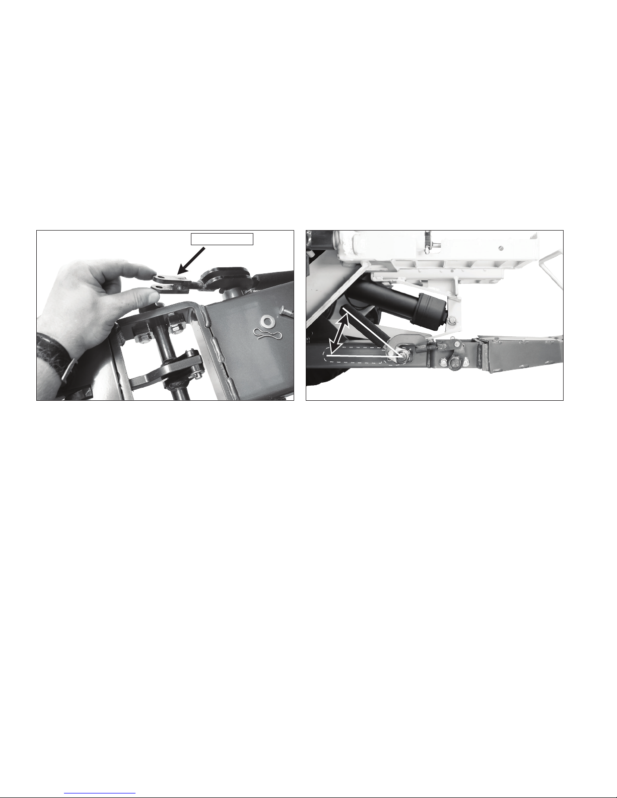
H19: Float Function Adjustment
• Non-Floating: Insert the clevis pin (Figure 2.9) through the rear actuator mount and secure with
the bowtie cotter pin. Install the clevis pin to allow for downward pressure on the implement.
• Floating: Remove the bowtie cotter pin, and remove the clevis pin from the rear actuator
mount (Figure 2.10). Removing the clevis pin will allow a free floating implement.
Actuator Motor (Ref)
Actuator Motor (Ref)
Clevis Pin
Clevis Pin
Removed
Figure 2.9: Non-Float Setting With Clevis Pin Installed
Figure 2.10: Float Setting With Clevis Pin Removed
5. Attach the PTO coupler to the tractor PTO shaft. Remove installation tool, and make sure the coupler is
secured properly to the tractor PTO shaft, and that the quick disconnect ring is in the LOCKED position as
shown in Figure 2.12. After installation, pull on the PTO coupler to check for security.
WARNING
The PTO shaft turns at high RPM. If the coupler is not locked to the shaft at the
tractor end, or if the yoke at the snowblower end is not secured properly, the drive
shaft can fly loose with great force, capable of causing serious injury or death.
IMPORTANT: DO NOT operate tractor with Coupler Installation Tool installed.
!
13
Page 21
IMPORTANT: To prevent damage to the mower, make sure the PTO quick
disconnect is securely locked on the tractor, with the locking balls fully seated in
the groove and the ring in the locked position (refer to the Quick Disconnect Ring
“Locked” Position illustration). After installation, pull on the PTO coupler to check
for security.
Coupler Ring in
Released Position
PTO Coupler
U-Joint
PTO Drive
Shaft
PTO Coupler
U-Joint
Internal Balls
Locked on Shaft
Coupler Ring in
Locked Position
PTO Drive
Shaft
Figure 2.11: Quick Disconnect Ring in “Released” Position
Figure 2.12: Quick Disconnect Ring in “Locked” Position
6. Attach the parallel bar to the female hitch and the implement adaptor using the two clevis pins and spring
clips. Adjust the length of the parallel bar by turning either end clockwise to shorten, or counterclockwise
to lengthen as needed to level the snowblower.
Rear Clevis Attach
Figure 2.13: Attach Parallel Bar
7. Insert the chute rotation handle into the rotation worm. Align the holes and lock in place with a 1/4 x 1
in. socket head cap screw and nylon locknut as shown in Figure 2.14.
Parallel Bar
Front Clevis Attach
14
Page 22
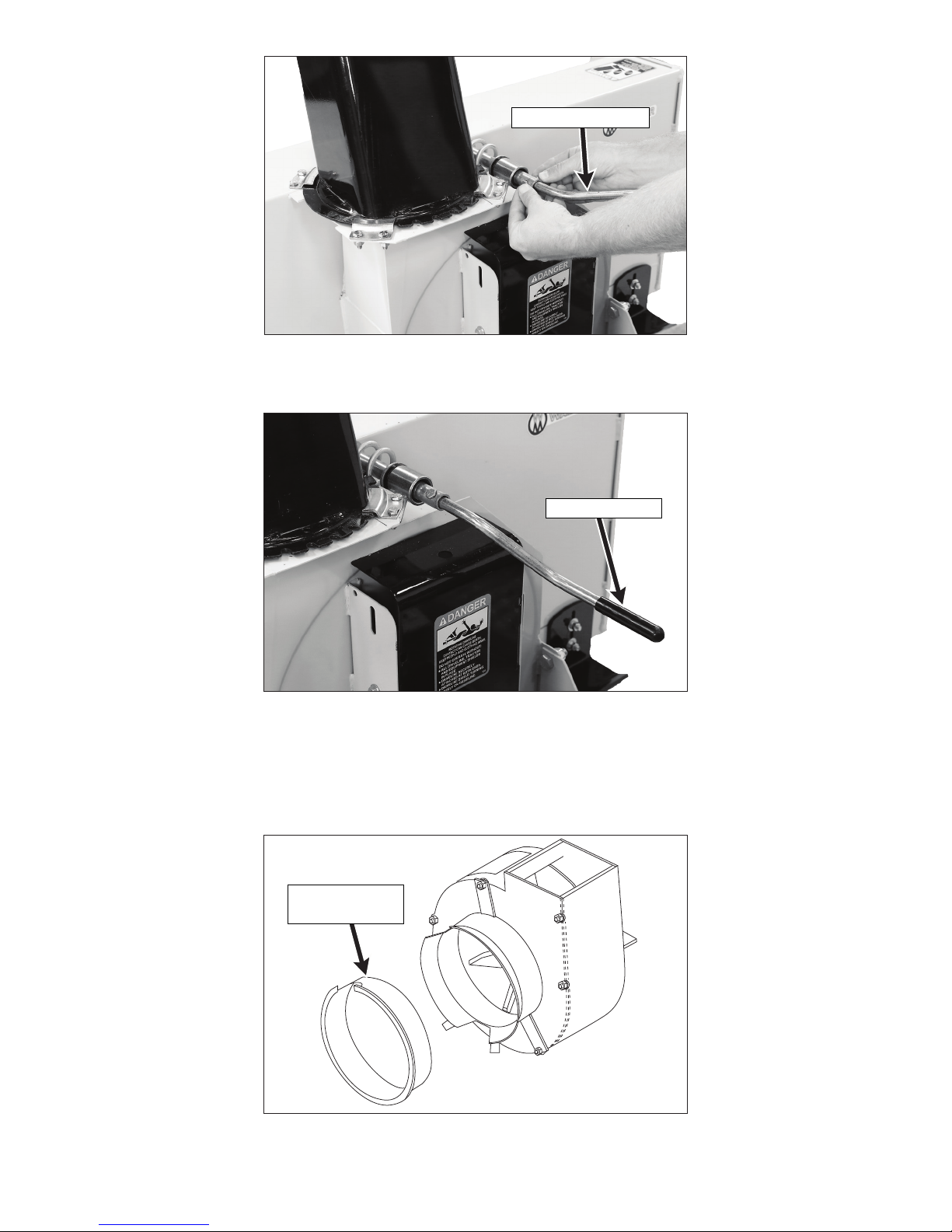
Rotation Handle
Figure 2.14: Install Chute Rotation Handle
8. Install the plastic handle grip on the chute rotation handle. Refer to Figure 2.15.
Handle Grip
Figure 2.15: Install Handle Grip
9. For GHS (Grass Handling System) equipped Walker tractors, install a blower intake cover (P/N 5595-2) in
the blower intake tube. The cover “unloads” the blower and seals the intake to eectively eliminate power
loss and noise when the blower is not being used.
Blower Intake
Cover
Figure 2.16: GHS Blower Intake Cover
15
Page 23

10. Counterweight should be installed on the tail of the tractor for stability when transporting the tractor with
the snowblower in raised position. Optional tail weights for the various tractor models are available from
your Walker dealer, or a sandbag or similar weight may be used.
16
Page 24

Operation
PREOPERATION CHECKLIST
Before operating the snowblower for the first time, and as a routine before daily operations, it is important
to make sure the machine is properly prepared and ready for operation. The following is a list of items to be
checked. For machines with frequent operation, some of these items will not need to be checked every day,
but the operator should be aware of the condition of each.
Tractor
CHECK TRACTOR PREOPERATING CHECKLIST
Refer to the appropriate Tractor Operator’s Manual.
CHECK TRACTOR TAILWEIGHT
Make sure sucient weight has been securely installed on rear of tractor (approximately 80 lbs. on most
tractor models).
CHECK OPTIONAL TIRE CHAINS
Tire chains should always be used when operating the machine in icy conditions. If the tractor is equipped
with the optional tire chains, make sure the chains are in good condition and are installed properly.
Implement Hitch
CHECK LIFT SWITCH OPERATION
Raise and lower the implement hitch to make sure the lift switch and linear actuator operate properly.
CHECK HITCH LOCKING LEVER
Inspect the locking mechanism for secure mounting of snowblower on hitch. Refer to Hitch Locking
Lever in the Implement Hitch Operator’s Manual.
Snowblower
CHECK SKID SHOE FOR WEAR AND PROPER ADJUSTMENT
See ADJUSTMENTS - Snowblower Skid Shoes in the Maintenance section of this manual.
ADJUST THE PARALLEL BAR SO THAT THE SNOWBLOWER RUNS LEVEL.
See step 5 in Installation instructions
CHECK CUTTING EDGE
Make sure the cutting edge is not damaged or worn beyond limits. Refer to REPAIRING/ REPLACING
PARTS - Snowblower Cutting Edge in the Maintenance section of this manual.
CHECK AUGER AND IMPELLER
• Make sure the auger and impeller are clear of snow and/or ice.
• Make sure the auger and impeller are free to rotate.
17
• Check that the auger flighting and impeller blades are in good condition and not bent.
Page 25
CHECK CHUTE AND DEFLECTOR
• Make sure the chute and deflector are not clogged with snow and/or ice.
• Turn the chute rotation handle and rotate the chute. The chute should rotate freely.
• Loosen the deflector position knobs to raise and lower the deflector. The deflector should
move freely. Retighten deflector position knobs with the deflector in the desired position.
CHECK GEARBOX OIL LEVEL
Inspect for any sign of an oil leak. Refer to LUBRICATION - Snowblower Gearbox in the Maintenance
section of this manual.
CHECK SHEAR BOLTS
Check the three (3) shear bolts, one on each auger section, and one between the fan and gearbox for
proper tightness, approximately 8 lb-ft (11 N•m).
CHECK REDUCTION CHAIN
Refer to LUBRICATION - Snowblower Reduction Chain in the Maintenance section of this manual.
Refer to ADJUSTMENTS Snowblower Reduction Chain Tension in the Maintenance section of this
manual.
SNOWBLOWER CONTROLS
Chute Rotation Handle
The chute rotation handle is located on the rear of the snowblower, behind and to the right of the discharge
chute (Figure 3.1). The chute rotates in a 228 degree arc, by cranking the rotation handle.
• Turning the handle clockwise rotates the chute to the right.
• Turning the handle counterclockwise rotates the chute to the left.
Rotate clockwise to
move chute to right;
opposite to left.
Figure 3.1: Chute Rotation Handle
Chute Rotation Handle
18
Page 26
Deflector Position Knobs
Set the angle of the deflector according to the distance the snow must be thrown. To adjust the deflector
angle:
1. Loosen the two knobs on the sides of the deflector.
2. Slide the deflector to the required angle, and securely retighten the two knobs.
Deflector Position
Knobs
Figure 3.2: Deflector Position Knobs
Raising/Lowering
The snowblower is raised or lowered using the toggle switch located on the FSC lever as shown in Figure 3.3.
• Move the switch forward to lower the implement.
• Move the switch backward to raise the implement.
Raise
Lower
19
Figure 3.3: Lift Control
Page 27

SNOWBLOWER OPERATION
CAUTION
Before operating the snowblower, read and understand all Safety
Instructions and Operating Instructions.
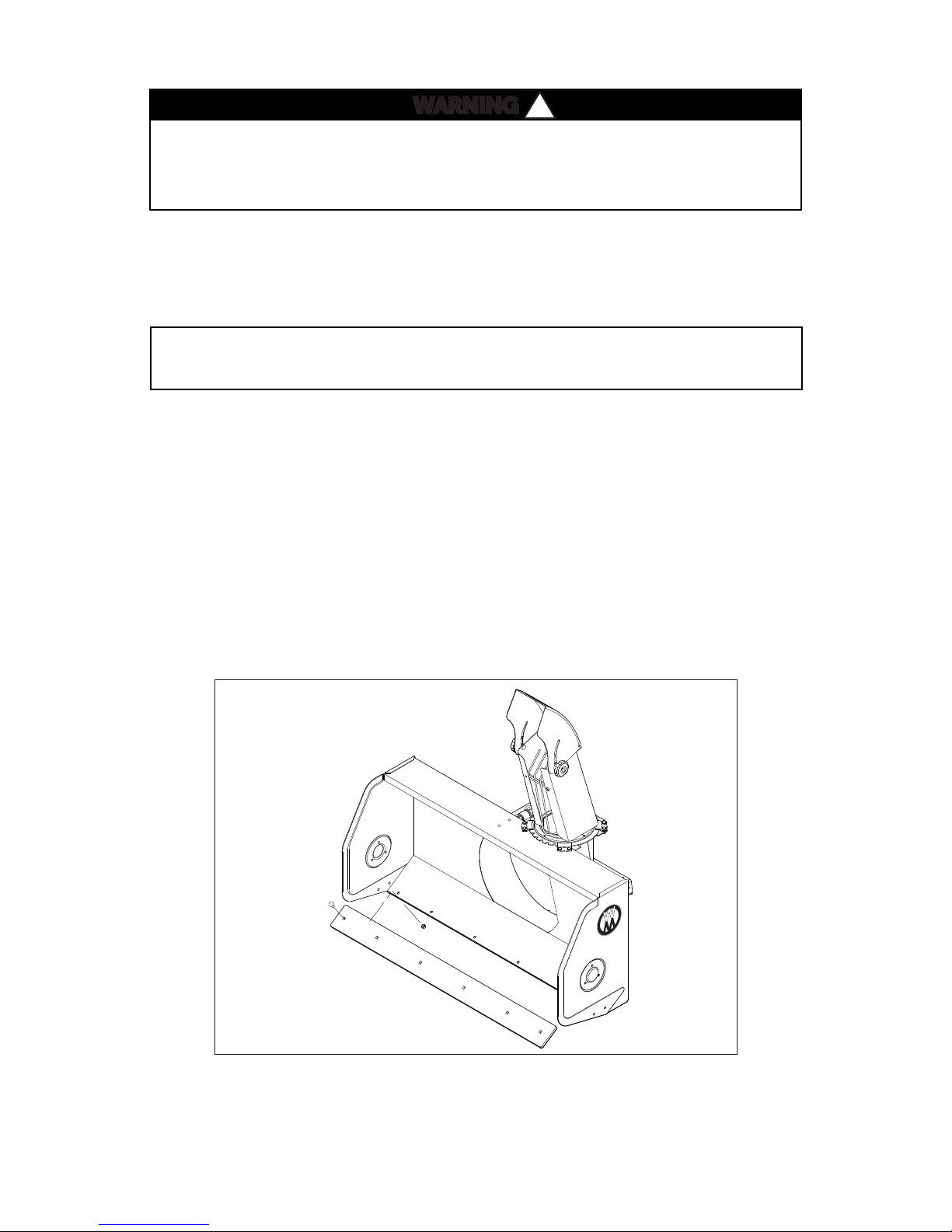
WARNING
If an implement is installed on the hitch, it must be locked in place
before beginning any operation.
Engaging the Snowblower
1. Set the engine throttle at about 1/3 speed. DO NOT attempt to engage the PTO clutch at high engine
speeds. This will drastically shorten drive belt life. Use only moderate engine speed when engaging the
PTO clutch.
2. Pull the PTO clutch lever SLOWLY AND SMOOTHLY to engage the snowblower.
NOTE: For cold weather operation, allow sucient time for the snowblower
components (i.e. gearbox oil) to warm up before beginning to blow snow.
!
!
DANGER
A safety interlock switch (seat switch) will cause the engine to stop if the PTO
clutch is engaged and the operator is not in the seat. The function of this
switch should be checked by the operator raising o the seat and engaging
the PTO clutch; the engine should stop. If the switch is not working, it
should be repaired or replaced before operating the snowblower. DO NOT
disconnect the safety switches; they are for the operator’s protection.
IMPORTANT: DO NOT engage the PTO clutch when transporting the
machine. DO NOT engage the PTO clutch with the PTO shaft disconnected
(the snowblower removed from the tractor).
!
20
Page 28

If the auger strikes a solid object or the machine begins to vibrate
abnormally, immediately disengage the PTO clutch, stop the engine,
and wait for all moving parts to stop. Disconnect the fuel solenoid
wire [diesel engines] or the spark plug wire(s) [gasoline engines] to
prevent accidental starting. Thoroughly inspect the snowblower
and repair any damage before starting the engine and operating the
machine. Make sure auger blades are in good condition and all bolts
are tight.
Recommendations for Snowblowing
IMPORTANT: Operate the engine at full speed when snowblowing
to allow the engine to produce full horsepower and to increase
eciency of the engine cooling system.
• When operating on a slope, reduce speed and use caution when starting, stopping, and
DANGER
!
maneuvering. Avoid sharp turns or sudden changes in direction.
• When blowing through deep snow drifts, let the snowblower work its way through the drifts.
For best results, raise the snowblower and remove a top layer of snow, then pass through the
area a second time to remove the remaining snow.
• When snowblowing, operate the engine at or near full throttle for the best snowblowing
action. The engine is designed to be operated at full speed.
• Use optional tire chains or optional all-terrain tires to improve traction.
• Disengage the PTO clutch to stop the snowblower when driving the machine but not blowing
snow.
• Avoid damage to property and extra snowblowing work by carefully choosing the direction
to move the snow. Orient the blower discharge away from people and property due to the
possibility of thrown objects.
• To momentarily increase traction in case the drive wheels are slipping, use the lift switch to
raise the snowblower slightly and transfer extra weight on the drive wheels.
Removing Snow
DO NOT blow snow with bystanders in the area (especially
children or pets).
A definite operating pattern is required to eciently clean snow from an area. Each pattern described below
clears all the snow in one pass (of the pattern) and prevents throwing snow in unwanted places.
21
DANGER
!
Page 29

IMPORTANT: DO NOT use the snowblower as a dozer blade to push snow.
No snow piled on this side
Snow thrown to this side only
Start Here
Finish Here
Rotate spout 180º
Rotate spout 180º
Rotate spout 180º
Let the snowblower work its way through deep snow. If the tractor is driven
forward into snow too fast, the snowblower may become overloaded and
clog.
When snow can be thrown to only one side of an area, use the pattern shown in Figure 3.4. Start on the
side farthest from where the snow will be thrown. At the end of the first pass, rotate the blower spout
180 degrees for the return pass. At the end of each following pass, rotate the spout 180 degrees to keep
throwing snow in the same direction.
Figure 3.4: Throw Snow to One Side
When snow can be thrown to both sides of an area, use the pattern shown in Figure 3.5. Start in the middle
with the blower spout directed to either the left or the right. Drive from one end to the other in an outward
spiral without changing the position of the blower spout to throw snow on both sides.
Snow thrown to both sides
Finish Here
Snow thrown to both sides
Start Here
Figure 3.5: Throw Snow to Both Sides
22
Page 30

Clogging Checklist
In case of clogging, the snow throwing action will decrease and finally stop. When this occurs, disengage the
PTO clutch, stop the engine, disconnect the fuel solenoid wire [diesel engines] or spark plug wire(s) [gasoline
engines], and remove the ignition key. Make sure all movement has stopped before attempting to unclog.
DANGER
!
DO NOT attempt to unclog the snowblower or make any adjustments with the
tractor engine running. Disengage the PTO clutch, stop the engine, and wait
for all moving parts to stop before unclogging the snowblower.
DANGER
!
NEVER place hands in the blower spout. DO NOT use hands or feet to unclog the
snowblower. Use a short stick or similar tool to remove any clogged material.
The following list of items should be checked if a pattern of clogging begins to develop. All of these items
are capable of causing clogging:
• Check that the inside of the snowblower housing is clean and free of snow and/or ice buildup.
• Check that the auger and impeller shear pins are present.
• Check that the auger is in good condition and not bent (both the auger flighting and the center
paddles).
• Check the inside of the blower chute for smoothness and freedom of obstruction.
Remember, anything that restricts airflow or material flow along the entire path from the auger to the blower
chute can cause clogging.
23
Page 31

Removing and Storage
H10 and H19 Instructions
1. Park the tractor on a level surface and lower the snowblower.
2. Remove the spring clip and clevis pin from the parallel bar at the hitch end, and remove the parallel bar
from the implement hitch.
3. Remove the linchpin from the quick hitch latch and place the hitch locking lever in the UNLOCKED
position.
4. Start the tractor and carefully back the tractor away from the snowblower.
DO NOT engage the PTO clutch with the PTO shaft disconnected (the
snowblower removed from the tractor).
5. Remove the PTO coupler from the tractor.
Storing the Snowblower
1. Clean and dry the snowblower thoroughly.
2. Repaint all parts from which paint has worn.
NOTE: Rustproofing or painting every year will prolong the life of the
snowblower components and moving parts.
3. Lubricate all moving parts. Apply lubricant liberally to all exposed surfaces to protect against rust.
4. List the replacement parts that will be needed before the next use.
5. Store the snowblower in a dry place.
24
Page 32

Maintenance
CAUTION
Maintenance procedures requiring special training or tools should be performed
by a trained technician.
WARNING
DO NOT perform any maintenance with the tractor engine running. Disengage
the PTO clutch, shut o the machine, and remove the ignition key before
performaing any maintenance on equipment.
MAINTENANCE SCHEDULE CHART RECOMMENDED SERVICE INTERVALS
Service Item Daily 8 Hours 25 Hours
Perform Preoperation Checklist X 17
Check Skid Shoe Wear/Adjustment
Check Cutting Edge Condition/Wear
Check Hitch Lock Tension (H19)
Lubricate Grease Fittings and Oil Points
Lubricate Reduction Drive Chain
Check Gearbox Oil Level
Check/Adjust Reduction Chain Tension
!
!
Reference
Page
X 31
X 28
X 33
X 26
X 26
X 25
X 26, 32
Check Condition of Drive Sprockets
LUBRICATION
Proper lubrication is an important maintenance procedure. It reduces wear and makes the machine quieter
and easier to operate.
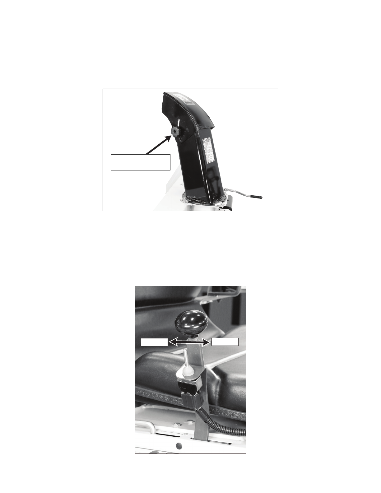
Snowblower Gearbox
The gearbox is permanently lubricated (oil filled) and sealed requiring no scheduled lubrication. However, the
gearbox oil seal(s) should be checked daily for any indication of an oil leak. If an oil leak is noted, the gearbox
should be repaired before further operation. Gearbox oil level can be checked as follows:
1. Clean the area around the oil fill plug located on the front of the gearbox as shown in Figure 4.1.
2. Remove the oil fill plug on the gearbox.
3. If the oil level is at the bottom of the plug hole, the gearbox is full. Reinsert the plug. If the oil level is
below the plug hole, add SAE E.P. (Extreme Pressure) 90W lubricant into the gearbox through the plug
hole until it starts to flow out.
X 20
25
Page 33
4. Wipe the threads of the gearbox plug before reinstalling.
5. Torque to 24 lb-in (3 N•m).
Oil Fill Plug
Figure 4.1: Oil Fill Plug
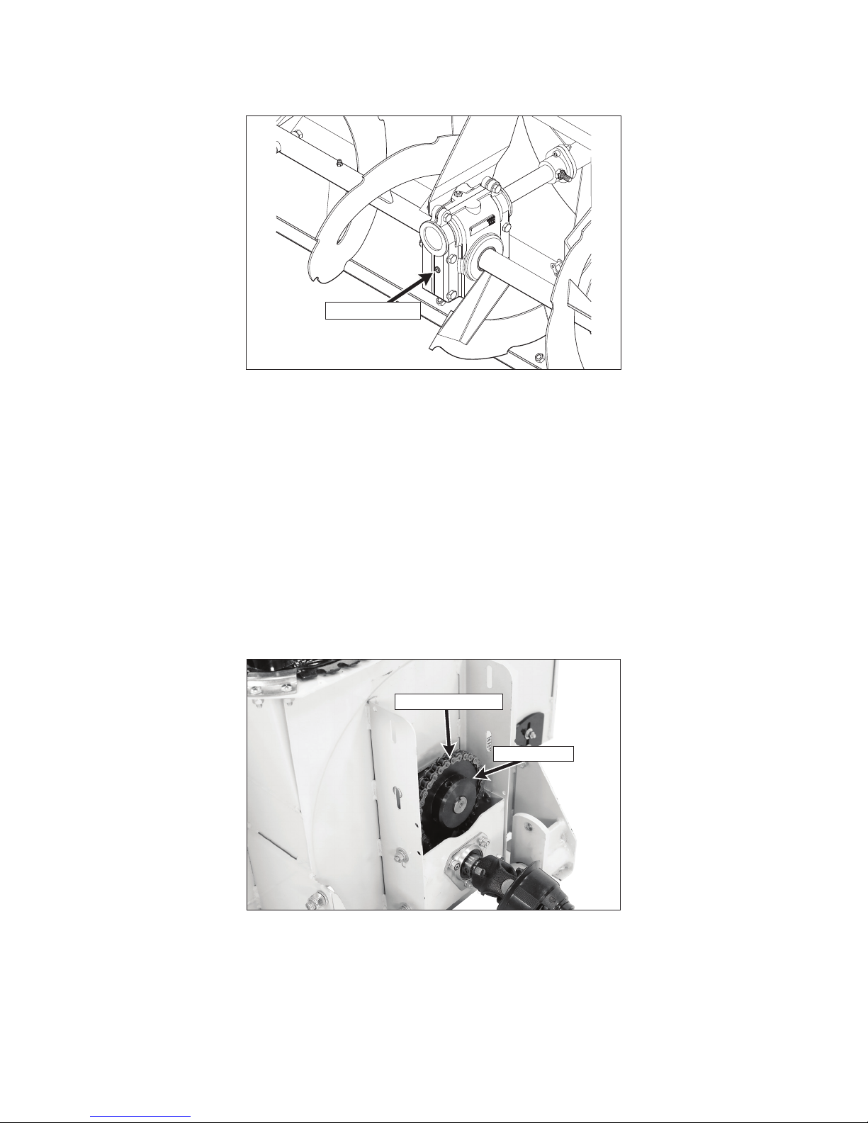
Snowblower Reduction Chain
Lubricate the reduction chain every 25 hours of operation. A light pentrating oil or special purpose chain oil
is recommended. Lubricate the reduction chain as follows:
1. Remove the bolts fastening the PTO guard to the reduction box and remove the guard.
2. Apply oil to the reduction chain.
3. Adjust the chain tension if necessary. Refer to REPLACING/REPAIRING - Snowblower Reduction Chain
and ADJUSTMENTS - Snowblower Reduction Chain Tension in this section.
4. Reinstall the PTO guard by reversing the removal procedure.
Reduction Chain
Sprocket
Figure 4.2: Snowblower Reduction Chain
Grease Fitting and Oil Point Lubrication
Lubricate the grease fittings and oil points every 25 hours of operation. Use SAE general purpose lithium or
molybdenum base grease for grease fittings and light machine oil (SAE 10) to lubricate oil points. Lubricate
the locations shown in the Lubrication Points Diagram on the following page.
26
Page 34

Ident
No.
Location Lubrication Type No. Places
1 Auger Sections Grease 2
2 Gearbox Oil* 1
3 Reduction Chain Oil** 1
4 Sprockets Oil 2
PTO Shaft Assembly
5
Grease 1
(Spline Slide Area)
6 PTO Universal Joints Grease 2
7 Quick Hitch Pivot Grease 1
* Gearbox is permanently lubricated and sealed requiring no scheduled lubrication. Oil level should be
checked only when an oil leak is noted. Refer to LUBRICATION Snowblower Gearbox in this section.
** Lubricate chain daily or every 25 hours of operation. Refer to LUBRICATION - Snowblower Reduction
Chain in this section.
Lubrication Points Diagram
3 and 4 not visible
(See Figure 4.2)
1
NOTE: Tractor and/or Implement Hitch
Lubrication Points are not shown here.
For Tractor and/or Implement Hitch
Lubrication Points, refer to the appropriate
OPERATOR’S MANUAL or ILLUSTRATED
PARTS MANUAL.
6
5
7
2
1
27
Page 35
REPLACING/REPAIRING PARTS
WARNING
To prevent accidental engine starting when replacing parts or repairing the
machine, remove the key from the ignition switch and disconnect the fuel
solenoid wire [diesel engines] or the spark plug wire(s) [gasoline engines].
Snowblower Cutting Edge
The cutting edge should be rotated or replaced before it is worn to the point that the snowblower housing can
make contact with the ground. Operating with an overly worn cutting edge will damage the snowblower.
NOTE: The cutting edge of the snowblower is reversible and needs to be replaced
only when both the top and bottom edges have worn.
Replace the snowblower cutting edge as follows:
1. Remove the six (6) 5/16-NC hex nuts and 5/16 in. lock washers from the rear of the snowblower housing,
behind the cutting edge. Remove the six (6) 5/16-NC x 1 in. carriage bolts from the front of the cutting
edge.
2. If only one edge of the blade is worn or damaged, rotate the blade 180 degrees so the new edge is now on
!
!
the bottom. Reinstall the cutting edge onto the snowblower housing by reversing the removal procedure.
3. If both edges are worn or damaged, remove the cutting edge and install a new one by reversing the
removal procedure.
Figure 4.3: Snowblower Cutting Edge
28
Page 36

Snowblower Reduction Chain
The reduction chain should be replaced if, when adjusted for proper tension, it can be pulled away from
the top of the reduction sprocket more than 1/2 the height of a tooth on the sprocket. Running the
snowblower with a worn chain increases wear on the sprockets.
1. Remove the bolts securing the PTO guard to the frame and remove the guard as shown in Figure 4.4.
2. Turn the reduction box drive shaft until the master link for the chain is accessible.
3. Remove the master link from the chain and remove the chain from the sprocket.
Figure 4.4: PTO Guard Removed
4. Place the new chain on the sprockets and install the master link. Install the clip on the master link
properly. The closed end of the clip should point in the direciton of chain travel as shown in Figure 4.5.
Direction of Chain Travel
Master Link
Closed End
of Clip
Figure 4.5: Replace Reduction Chain
Plate
5. Adjust the chain tension. Refer to ADJUSTMENTS - Snowblower Reduction Chain Tension in this section.
6. Reinstall the PTO guard by reversing the removal procedure.
29
Page 37

Snowblower Reduction Sprockets
A sprocket should be replaced when the teeth become asymmetric (when the front side of a tooth is a
dierent shape than the back side of the tooth) as shown in Figure 4.6.
Symmetric (Acceptable)
Asymmetric (Replace)
Figure 4.6: Reduction Sprocket Wear
NOTE: Generally, a small sprocket wears faster than a large sprocket.
Replacing Drive Shaft with Sprocket (P/N I153)
1. Remove the PTO guard and reduction chain. Refer to REPLACING/REPAIRING PARTS - Snowblower
Reduction Chain in this section.
2. Remove the bolt and set screw retaining the U-joint shaft assembly to the drive shaft, and remove the
U-joint shaft assembly from the drive shaft. Remove the three (3) carriage bolts, nuts and washers from
the rear bearing flange.
3. Remove the four (4) carriage bolts and nuts securing the reduction box assembly to the frame and remove
the reduction box assembly.
4. Loosen the set screws that secure the two (2) bearing collars to the shaft, and remove the shaft from the
reduction box. Also remove the rear bearing from the shaft.
5. Install the new drive shaft (with sprocket) into the reduction box by reversing the removal procedure.
6. Reinstall the reduction box and chain by reversing the removal procedure.
7. Lubricate and tension the reduction chain. Refer to LUBRICATION - Snowblower Reduction Chain, and
ADJUSTMENTS - Snowblower Reduction Chain Tension in this section. Reinstall the PTO guard.
30
Page 38

Replacing Large Sprocket (P/N I161)
1. Remove the PTO guard cover and reduction chain. Refer to REPLACING/REPAIRING PARTS - Snowblower
Reduction Chain in this section.
2. Remove the four (4) carriage bolts and nuts securing the reduction box assembly to the frame and remove
the reduction box assembly.
3. Remove set screws on the large sprocket, and remove large sprocket from the gearbox drive shaft.
4. Install new large sprocket by reversing the removal procedure.
5. Reinstall the reduction box and chain by reversing the removal procedure.
6. Lubricate and tension the reduction chain. Refer to LUBRICATION - Snowblower Reduction Chain, and
ADJUSTMENTS - Snowblower Reduction Chain Tension in this section. Reinstall the PTO guard.
ADJUSTMENTS
Snowblower Skid Shoes
Adjust the skid shoes to allow the required clearance under the blade. On level, paved surfaces, adjust the
skid shoes to allow 0 to 1/4 in. (0 to 6 mm) clearance between the cutting edge and the surface. On uneven
or gravel surfaces, allow 1/2 to 5/8 in. (13 to 16 mm) clearance, depending on the size of the gravel. Refer
to Figure 4.7.
0 to 1/4 in. (5 to 6 mm)
clearance for level, paved surfaces
31
Figure 4.7: Skid Shoe Height Adjustment
1/2 to 5/8 in. (13 to 16 mm)
clearance for uneven or gravel surfaces
Page 39

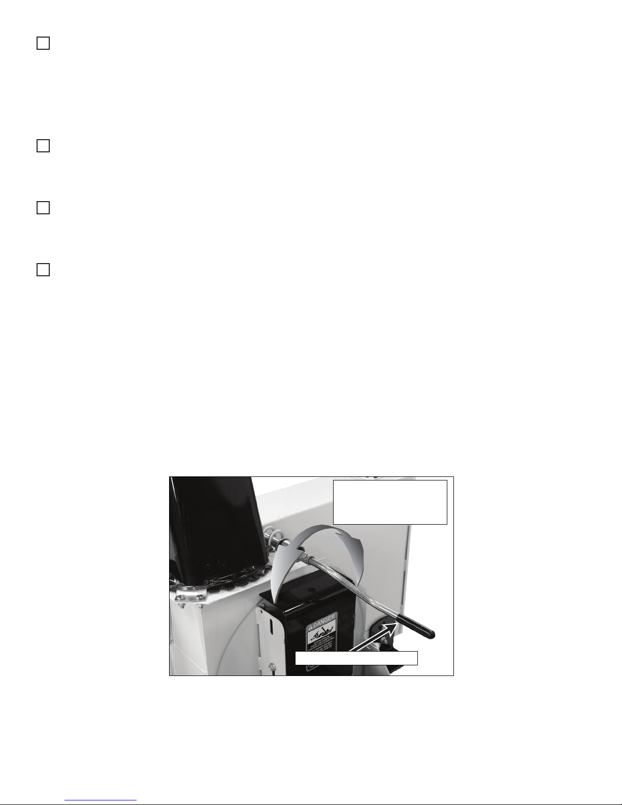
Snowblower Reduction Chain Tension
Adjust the tension on the reduction chain as follows:
1. Remove PTO guard covering the reduction box.
2. Loosen the four (4) carriage bolts and nuts securing the reduction box assembly to the frame.
3. Using a pry bar, apply leverage to push the reduction box assembly down to increase tension on the
chain. The chain should have 1/16 to 1/8 in. of slack.
4. While applying downward pressure to maintain chain tension, tighten the four (4) carriage bolts and nuts
to 25 ft•lbs (34 N•m) as shown in Figure 4.8.
Figure 4.8: Tensioning Reduction Chain
5. After torquing fasteners, verify correct chain tension as described in step 3.
6. Reinstall the PTO guard.
1/16 in. to
1/8 in
Figure 4.9: Correct Chain Tension
1/16 in. to
1/8 in
32
Page 40
H19 Hitch Lock Tension Adjustment
After installing an implement onto the hitch, the hitch lock clevis will need to be adjusted according to the
following procedure:
1. Adjust the H19 hitch lock clevis to properly secure the implement. To adjust the tension on the tongue
latch, remove the bowtie clip and the clevis pin as shown in Figure 4.10, and twist the male clevis clockwise
to tighten, or counterclockwise to loosen, as needed.
2. The hitch lock lever should travel approximately 2” at grip end after implement hitch adapter is fully seated
on implement hitch tongue as shown in Figure 4.11.
3. Repeat adjustment procedure after first 15 minutes of operation after installing implement.
4.
Male Clevis
Figure 4.10: Hitch Lock Clevis
2”
Figure 4.11: Hitch Lock Arm Travel
33
Page 41

This page left intentionally blank
34
Page 42

SNOWBLOWER DRIVE COMPONENTS H12
ITEM WLK RAD
NO. PART PART DESCRIPTION NO.
NO. NO. REQ’D
Driveline and Auger Components
1 I394 657762 Decal, Rotating Auger 2
2 NS 655683 Decal, Check Oil Level 1
3 NS 657804 Decal, Lubricate Chain 1
4 I120 656589 Bearing Flange 6
5 I434 665495 Bearing With Locking Collar 1
6 F168 5/16 Split Lock Washer 15
7 I163 656570 40 x 38 Chain 1
8 I161 656543 Sprocket (H40B32) 1
9 I512 665494 1” Bearing 4
(Includes Item # F309)
10 O/L 5/16-NC x 5/8 Carriage Bolt 6
11 I153 657250 Drive Shaft (with Sprocket), 1
H40C11
12 6671-10 U-Joint Shaft Assembly, Spline 1
(Includes Items # 27-29)
13 I395 657763 Decal, Rotating Driveline 1
14 6671-1 6671-1 PTO Outer Shield 1
15 6651-5 Bearing & Retainer Kit 1
16 NS 657346 Decal, Use Shear Bolts 1
17 I543 0300002 Carriage Bolt, 5/16 x 3/4 3
18 I105 656053 Shear Bolt (1/4-NC x 1) 1
With Locknut
19 I209 4300055 Bushing 2
20 I102 657327 Fan Assembly 1
(Includes Item # 33)
21 I104 655874 Fan Adapter Shear Plate 1
22 666732 Auger, LH 1
23 I114 667786 Shear Bolt (5/16-18 x 2-1/4) 2
Lock & Nut
24 I113 657334 Bearing Flange 2
25 5830 654106 Grease Fitting 2
26 I130 655967 Woodruff Key 1
27 I129 657286 Output Shaft 1
28 I200 4500035 Gearbox 1
(Includes Items # 1-14)
I101 663030 Gearbox (Usimax) 1
NS 665775 Seal Kit 1
29 666731 Auger, RH 1
30 I106 0100024 5/16-18 x 2 Hex Bolt, Grade 8 1
ITEM WLK
NO. PART DESCRIPTION NO.
NO. REQ’D
Fasteners
F004 1/4-20 Keps Nut 1
F034 5/16-18 x 3/4 Hex Bolt 6
F113 5/16-18 x 5/16 Set Screw 2
F149 1/4 x 1/4 x 1-1/2 Key 1
F235 5/16-18 x 2-1/2 Hex Bolt 4
F255 5/16-18 x 1-1/2 Hex Bolt 2
F271 1/4-20 x 2-1/4 Hex Bolt 1
F309 1/4-28 x 1/4 Set Screw 5
F318 3/8-16 x 3/4 SQH Set Screw 1
F447 1/4 x 1/4 x 1 Key 1
NOTE: Decals are illustrated in greater detail on pages 6-7 of this
manual.
NOTE: NS items are “Not Sold” by Walker Manufacturing.
NOTE: O/L indicates “Obtain Locally.”
35
Beginning S/N 21508289
Eective Date 03.25.15
Use only genuine Walker® replacement parts
Page 43

28
F255
F255
26
27
25
29
23
25
24
19
20
19
30
18
17
21
18
F309
9
24
6
23
22
23
23
F020
F020
F020
F020
6
F034
F309
9
F034
F318
F004
12
F271
F149
8
7
F113
F447
F113
11
10
10
4
4
6
F020
4
4
F020
20
4
18
6
F020
F309
F309
F309
9
5
9
3
2
1
1
16
13
14
15
SNOWBLOWER DRIVE COMPONENTS H12
36
Page 44

SNOWBLOWER HOUSING COMPONENTS H12
ITEM WLK RAD
NO. PART PART DESCRIPTION NO.
NO. NO. REQ’D
Chute Rotation Assembly
1 I169 661168 Chute, Base and Knobs 1
(Includes items 1-5, 7,8, and 16)
2 I396 657761 Decal, Keep Hands Out 1
3 I172 658468 7/16 Nylon Washer 2
4 I171 658467 11/32 Nylon Washer 2
5 I170 657309 5/16-18 Knob 2
6 I175 657308 Hand Guard 1
7 O/L 1/4 Lock Washer 8
8 I522 657333 Retaining Plate 4
9 I183 657338 Nylon Ring 1
10 I524 656797 Plastic Handle (1/2 x 3) 1
11 I188 661035 Crank Handle 1
12 I187 657493 Rear Shaft Support 1
13 I186 657336 1-11/16 Plastic Bushing 1
14 I185 657733 Rotation Worm 1
15 I184 657335 1-5/16 Plastic Bushing 1
16 I397 660988 Decal, Safety Procedures 1
Snowblower Mount Assembly
ITEM WLK RAD
NO. PART PART DESCRIPTION NO.
NO. NO. REQ’D
Fasteners
F005 1/4-20 ESNA Nut 1
F016 1/2-13 Self-Locking Nut 4
F020 5/16-18 ESNA Nut 18
F032 1/4-20 x 3/4 Hex Bolt 10
F036 1/4-20 x 1/2 SBH Screw 1
F049 5/16 SAE Washer 2
F051 3/8 SAE Washer 10
F168 5/16 Split Lock Washer 10
F169 5/16 x 1 Carriage Bolt 6
F174 1/2-13 x 1-1/4 Hex Bolt 4
F175 1/2 Split Lock Washer 4
F381 1/4-20 Hex Nut 10
NOTE: Decals are illustrated in greater detail on pages 6-7 of this
manual.
NOTE: O/L indicates “Obtain Locally.”
17 4407-5 Bow Tie Cotter Pin 2
18 6621-1 Clevis Pin (1/2 x 2) 2
19 6670-2 Parallel Bar Assembly 1
20 5830 654106 Grease Fitting 1
21 I189 669691 Quick Hitch (Female) 1
Reduction Box Assembly
22 I196 669612 PTO Guard 1
23 O/L 5/16-NC x 1/2 Serrated 2
Flange Bolt
24 I164 657355 Reduction Box 1
25 I543 0300002 Carriage Bolt, 5/16 x 3/4 10
Snowblower Frame Assembly
26 5800-9 2500938 Decal, Walker Round (4-3/4”) 2
27 I125 669674 Skid Shoe 2
28 6625-8 42” Cutting Edge 1
29 669690 Frame 1
30 I205 657332 Worm Gearbox Support 1
31 5809-2 2500937 Decal, Walker Logo 1
32 O/L 5/16-NC x 3/4 Hex Bolt 2
37
Beginning S/N 21508289
Eective Date 03.25.15
Use only genuine Walker® replacement parts
Page 45
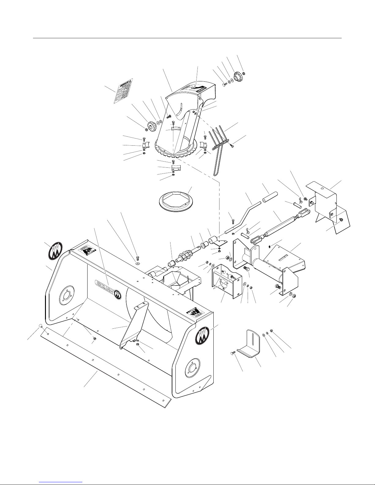
SNOWBLOWER HOUSING COMPONENTS H12
F020
5
F169
12
7
F381
F051
3
7
F016
4
F381
F049
F036
F175
6
F032
23
11
F005
F174
17
10
18
19
17
18
20
21
23
22
F381
9
14
F020
2
F032
8
13
F168
1
16
F169
3
4
5
F020
F032
F032
8
7
F381
32
F051
31
26
29
8
F032
8
7
F381
15
25
24
F051
26
30
25
28
F020
F020
F020
F168
F169
F168
F020
F174
27
F175
F016
F051
F168
F020
38
Page 46

SNOWBLOWER DRIVE COMPONENTS H17
ITEM WLK RAD
NO. PART PART DESCRIPTION NO.
NO. NO. REQ’D
Driveline and Auger Components
1 I394 657762 Decal, Rotating Auger 2
2 NS 655683 Decal, Check Oil Level 1
3 NS 657804 Decal, Lubricate Chain 1
4 I120 656589 Bearing Flange 6
5 I434 665495 Bearing With Locking Collar 1
6 I163 656570 40 x 38 Chain 1
7 I161 656543 Sprocket (H40B32) 1
8 I512 665494 1” Bearing 4
(Includes Item # F309)
9 O/L 5/16-NC x 5/8 Carriage Bolt 6
10 I153 657250 Drive Shaft (with Sprocket), 1
H40C11
11 6671-10 U-Joint Shaft Assembly, Spline 1
(Includes Items # 25-27)
12 I395 657763 Decal, Rotating Driveline 1
13 6671-1 PTO Outer Shield 1
14 6651-5 Bearing & Retainer Kit 1
15 NS 657346 Decal, Use Shear Bolts 1
16 I543 0300002 Carriage Bolt, 5/16 x 3/4 3
17 I105 656053 Shear Bolt (1/4-NC x 1) 1
With Locknut
18 I209 4300055 Bushing 2
19 I102 657327 Fan Assembly 1
(Includes Item # 31)
20 I104 655874 Fan Adapter Shear Plate 1
21 666738 Auger, LH 1
22 I114 667786 Shear Bolt (5/16-18 x 2-1/4) 2
Lock & Nut
23 I113 657334 Bearing Flange 2
24 5830 654106 Grease Fitting 2
25 I130 655967 Woodruff Key 1
26 660390 Output Shaft 1
27 I200 4500035 Gearbox 1
(Includes Items # 1-13)
I101 663030 Gearbox (Usimax) 1
NS 665775 Seal Kit 1
28 666737 Auger, RH 1
29 I106 0100024 5/16-18 x 2 Hex Bolt, Grade 8 1
ITEM WLK RAD
NO. PART PART DESCRIPTION NO.
NO. NO. REQ’D
Fasteners
F004 1/4-20 Keps Nut 1
F020 5/16-18 ESNA Nut 22
F034 5/16-18 x 3/4 Hex Bolt 6
F113 5/16-18 x 5/16 Set Screw 2
F149 1/4 x 1/4 x 1-1/2 Key 1
F168 5/16 Split Lock Washer 15
F235 5/16-18 x 2-1/2 Hex Bolt 4
F255 5/16-18 x 1-1/2 Hex Bolt 2
F271 1/4-20 x 2-1/4 Hex Bolt 1
F309 1/4-28 x 1/4 Set Screw 5
F318 3/8-16 x 3/4 SQH Set Screw 1
F447 1/4 x 1/4 x 1 Key 1
NOTE: Decals are illustrated in greater detail on pages 6-7 of this
manual.
NOTE: All NS items are not sold by Walker Manufacturing.
NOTE: O/L indicates “Obtain Locally.”
39
Beginning S/N 21516633
Eective Date 09.22.15
Use only genuine Walker® replacement parts.
Page 47
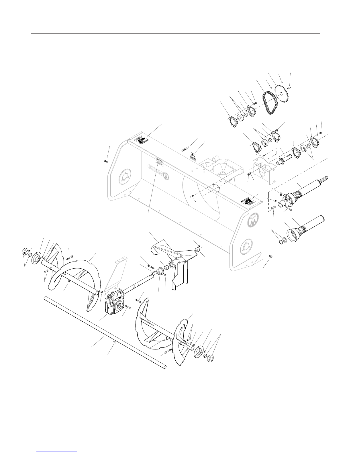
SNOWBLOWER DRIVE COMPONENTS H17
F113
10
F271
F447
9
F309
4
11
12
13
F020
F168
4
8
7
6
F113
4
F020
F168
5
4
1
2
F034
15
23
F168
F020
F309
8
22
28
19
29
17
18
3
16
17
18
F309
4
F309
8
4
9
F168
F020
F318
1
F004
F149
14
F034
22
24
F020
27
26
25
F255
F255
24
F020
20
21
22
F020
22
F168
23
F309
8
40
Page 48

SNOWBLOWER HOUSING COMPONENTS H17
ITEM WLK RAD
NO. PART PART DESCRIPTION NO.
NO. NO. REQ’D
Chute Rotation Assembly
1 I169 661168 Chute, Base and Knobs 1
(Includes items 1-5,7,8, and 16)
2 I396 657761 Decal, Keep Hands Out 1
3 I172 658468 7/16 Nylon Washer 2
4 I171 658467 11/32 Nylon Washer 2
5 I170 657309 5/16-18 Knob 2
6 I175 657308 Hand Guard 1
7 O/L 1/4 Lock Washer 8
8 I522 657333 Retaining Plate 4
9 I183 657338 Nylon Ring 1
10 I524 656797 Plastic Handle (1/2 x 3) 1
11 I188 661035 Crank Handle 1
12 I187 657493 Rear Shaft Support 1
13 I186 657336 1-11/16 Plastic Bushing 1
14 I185 657733 Rotation Worm 1
15 I184 657335 1-5/16 Plastic Bushing 1
16 I397 660988 Decal, Safety Procedures 1
Snowblower Mount Assembly
17 4407-5 Bow Tie Cotter Pin 2
18 6621-1 Clevis Pin (1/2 x 2) 2
19 6670-7 Parallel Bar Assembly 1
20 669693 Quick Hitch (Female) 1
21 5830-3 Grease Fitting (45 Deg) 1
ITEM WLK RAD
NO. PART PART DESCRIPTION NO.
NO. NO. REQ’D
Snowblower Frame Assembly
26 5800-9 2500938 Decal, Walker Round (4-3/4”) 2
27 I125 669674 Skid Shoe 2
28 6625-9 659862 50” Cutting Edge 1
29 669692 Frame 1
30 I205 657332 Worm Gearbox Support 1
31 5809-2 2500937 Decal, Walker Logo 1
Fasteners
F003 1/4-28 Hex Nut 10
F005 1/4-20 ESNA Nut 1
F016 1/2-13 Self-Locking Nut 4
F020 5/16-18 ESNA Nut 18
F032 1/4-20 x 3/4 Hex Bolt 10
F034 5/16-18 x 3/4 Hex Bolt 2
F036 1/4-20 x 1/2 SBH Screw 1
F049 5/16 SAE Washer 2
F051 3/8 SAE Washer 10
F168 5/16 Split Lock Washer 10
F169 5/16 x 1 Carriage Bolt 6
F175 1/2 Split Lock Washer 4
F469 1/2-13 x 1-1/4” Hex Bolt, GR 5 4
NOTE: Decals are illustrated in greater detail on pages 6-7 of this
manual.
Reduction Box Assembly
22 I196 669612 PTO Guard 1
23 O/L 5/16-NC x 1/2 Serrated 2
Flange Bolt
24 I164 657355 Reduction Box 1
25 I543 0300002 Carriage Bolt, 5/16 x 3/4 10
NOTE: O/L indicates “Obtain Locally.”
41
Beginning S/N 21516633
Eective Date 09.22.15
Use only genuine Walker® replacement parts.
Page 49

SNOWBLOWER HOUSING COMPONENTS H17
F020
5
F032
F169
4
3
F003
F049
6
F032
7
10
11
17
18
19
8
F003
9
2
1
16
F169
3
4
5
F020
F032
F032
8
7
F003
8
F032
8
7
F003
23
22
12
7
F003
F016
25
F036
17
F005
18
20
F175
F469
21
F469
24
F051
F020
F168
26
F169
F175
F016
F020
F168
F051
27
23
F034
31
26
29
25
F020
F051
13
15
30
F168
F020
28
14
F020
F168
F051
42
Page 50

OPERATOR’S NOTES
43
Page 51

LIMITED WARRANTY
FOR WALKER
TWOSTAGE SNOWBLOWER
1.
2.
3.
What this warranty covers, and for how long:
Walker Manufacturing company will, at its option, repair or replace, without charge, any part covered
by this warranty which is found to be defective in material and/or workmanship within one (1) year after
date of sale to the original retail purchaser unless the product is used for rental purposes, in which case
this warranty is limited to ninety (90) days. At Walker’s request, customer will make the defective part
available for inspection by Walker and/or return the defective part to Walker, transportation charges
prepaid. All parts and components of the Walker two-stage snowblower are covered by this warranty.
What this warranty does not cover:
A. This warranty does not cover defects caused by depreciation or damage caused by normal wear,
accidents, improper maintenance, improper use or abuse of the product, alterations, or failure to follow
the instructions contained in the Operator’s Manual for operation and maintenance.
B. The customer shall pay any charges for making service calls and/or for transporting the attachment
to and from the place where the inspection and/or warranty work is performed.
How to obtain service under this warranty:
Warranty service can be arranged by contacting the dealer where you purchased the machine or by
contacting Walker Manufacturing Company, 5925 East Harmony Road, Ft. Collins, CO 80528. Proof of
the date of purchase may be required to verify warranty coverage.
4.
Warranty limitation:
A. THERE IS NO OTHER EXPRESS WARRANTY. ANY WARRANTY THAT MAY BE IMPLIED FROM THIS
PURCHASE INCLUDING MERCHANTABILITY AND FITNESS FOR A PARTICULAR PURPOSE IS HEREBY
LIMITED TO THE DURATION OF THIS WARRANTY AND TO THE EXTENT PERMITTED BY LAW ANY
AND ALL IMPLIED WARRANTIES ARE EXCLUDED. Some states do not allow limitations on how long an
implied warranty lasts, so the above limitations may not apply to you.
B. WALKER WILL NOT BE LIABLE FOR ANY INCIDENTAL, CONSEQUENTIAL, OR SPECIAL DAMAGES
AND/OR EXPENSES IN CONNECTION WITH THE PURCHASE OR USE OF THE MACHINE. Some
states do not allow the exclusion or limitation of incidental or consequential damages, so the above
limitation(s) or exclusion(s) may not apply to you.
C. Only the warranty expressed in this limited warranty shall apply and no dealer, distributor, or individual
is authorized to amend, modify, or extend this warranty in any way. Accordingly, additional statements
such as dealer advertising or presentations, whether oral or written, do not constitute warranties by
Walker, and should not be relied upon.
D. This warranty gives you specific legal rights, and you may also have other rights which vary from
state to state.
44
Page 52

WALKER MFG. CO. 5925 HARMONY ROAD, FORT COLLINS, CO. 80528 9702215614
FORM NO. 041217
PRINTED IN USA
 Loading...