

Page 1

H11 48 in Dozer Blade
H16 60 in Dozer Blade
Operator’s Manual
Assembly, Attaching, Removing, Operation and Maintenance
H11 compatible with Models C, D, H, T
H16 compatible with Models D, H, T
Please Read and Save These Instructions
For Safety, Read All Assembly and Opeartion Instructions
Prior to Operating Attachment
Beginning S/N: 14-0201
Eective Date: 09/17/14
P/N: 6625-12
Page 2

Foreword
Thank you. . .for purchasing a Walker Dozer Blade Attachment. Every eort has been made to provide
you with the most reliable machine on the market, and we are sure you will be among our many satisfied
customers. If for any reason this product does not perform to your expectations, please contact your local
dealer. Every customer is important to us. Your satisfaction is our goal.
Please. . .read this manual thoroughly! Before you operate your machine, please read this entire manual.
Some of the information is crucial for proper operation - it will help protect your investment and ensure
that the machine performs to your satisfaction. Some of the information is important to your safety, and
must be read and understood to help prevent possible injury to the operator or others. If anything in this
manual is confusing or hard to understand, please contact your local authorized dealer or call our service
department, at (970) 221-5614, for clarification before operating or servicing this machine.
All shields and guards must be in place for the proper and safe operation of this machine. Where they are
shown removed in this manual, it is for illustration purposes only. Do not operate this machine unless all
shields and guards are in place.
Walker Mfg. Co. is continually striving to improve the design and performance of its products. We reserve
the right to make changes in specifications and design without thereby incurring any obligation relative to
previously manufactured products.
Sincerely,
WALKER MANUFACTURING COMPANY
Bob Walker, President
i
Page 3

Table of Contents:
Assembly
Attaching Blade to Tractor
Removing Blade from Tractor
Operation
Maintenance
Parts List/Diagram
Warranty
1
4
7
8
11
13
20
HIGHLIGHTED INFORMATION
Walker Manufacturing recommends that any service requiring special training or tools be
performed by an authorized Walker Mower Dealer. There are several general practices
to be aware of in the area of safety. Most accidents associated with the operation or
maintenance of a Walker product are caused by disregarding basic safety precautions or
specific warnings. Such accidents, in most cases, can be prevented by being aware of the
dangers present. Information of special importance has been highlighted in bold type.
H11 48” Dozer Blade:
• The following are required for mounting the H11 48” Dozer Blade:
- C, T, D tractors: H10 Implement Mount Hitch
- H tractors: H19 Implement Mount Hitch
• The following option is available for the H11 48” Dozer Blade:
- Dozer Blade Polyurethane Cutting Edge Kit 48” (6625-10)
H16 60” Dozer Blade:
• The following are required for mounting the H16 60” Dozer Blade:
- T, D tractors: H10 Implement Mount Hitch
- H tractors: H19 Implement Mount Hitch
• The following option is available for the H16 60” Dozer Blade:
- Dozer Blade Polyurethane Cutting Edge Kit 60” (6625-11)
ii
Page 4

Dozer Blade Assembly
Parts Included in Bag:
Name:
5/16-18 ESNA Nut
3/16 x 1-1/8 Roll Pin
5/16 x 7/8 x .125 Washer
Extension Spring
5/16-18 x 2 Eye Bolt
Quantity:
1
1
1
1
1
Recommended tools:
• Ball peen hammer
• Tapered punch
• Wrench/Socket wrench
• Pliers
1
Page 5
Dozer Blade Assembly
1. Remove blade mount, hitch adapter and dozer blade from boxes; lay blade mount on flat
surface; set hitch adapter aside. Ensure all parts are included in the parts bag.
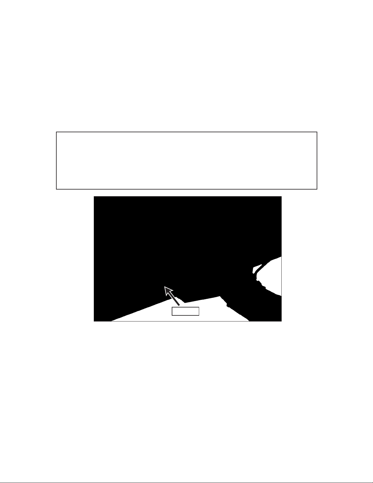
2. Remove the pivot shaft from the back of dozer blade and align the pivot shaft sockets on
the blade mount and dozer blade.
3. Begin feeding the pivot shaft through by hand from left to right through the pivot shaft
sockets. Then, using a hammer and punch, tap the pivot shaft through the pivot shaft
sockets making sure to align the roll pin holes on the left hand side. The pivot shaft should
have a snug fit in the sockets with no play or looseness.
NOTE: If needed, tap the pivot shaft back through the left pivot shaft
socket approximately one inch and, using pliers rotate the pivot shaft
to more closely align the roll pin holes. Tap pivot shaft back in place,
and using a tapered punch inserted into roll pin holes, maneuver pivot
shaft into alignment.
Roll pin
Figure 1.1
4. After ensuring proper alignment of the roll pin guides, use a hammer to tap roll pin into
place as shown in figure 1.1.
2
Page 6

Dozer Blade Assembly
5. Loop the extension spring through the spring mount tab in the center of the blade
mount. Loop the eye bolt over the other end of the extension spring, and pull up on the
extension spring so the threads of the eye bolt protrude through the eye bolt bracket as
shown in figure 2.1.
NOTE: Stretching the spring to fit through the bracket may require
two hands and an assistant may be needed to install the ESNA nut.
Place washer over the eye bolt and begin threading the ESNA nut onto eye bolt enough to
hold eye bolt in place. Hold the eye bolt with pliers, and finish tightening the ESNA nut as
shown in figure 2.2.
Figure 2.1 Figure 2.2 Figure 2.3
NOTE: Eye bolt threads need to protrude through the ESNA nut
by at least 2 threads as in figure 2.3. See Dozer Blade Operation
section for additional notes on the extension spring.
3
Page 7

Attaching Dozer Blade to Tractor
NOTE: Depending on the tractor, either the H10 or H19 Implement Mount Hitch will
need to be installed on the tractor prior to attaching the dozer blade. See page ii to
determine the correct implement mount hitch.
1. Method 1: When attaching the dozer blade to the implement hitch, slide hitch adapter
onto implement hitch.
Figure 3.1 Figure 3.2
Method 2: Lower the hitch adapter tongue until it is just above the ground, and slowly
drive forward until the tongue is fully engaged in the dozer blade receiver.
4
Page 8
Attaching Dozer Blade to Tractor
2. Once the hitch adapter tongue is fully engaged into the receiver, lock the dozer blade in
place.
H10 Instructions
• On the H10 implement hitch, pull hitch lock lever fully forward and down to the
LOCKED position (figure 3.3), and secure the quick hitch latch with the linch pin
(figure 3.4). Close PTO shield.
Figure 3.3 Hitch Lock Lever in “Locked” Position
Figure 3.4
H19 Instructions
• On the H19 implement hitch, pull hitch lock lever fully to the rear and down to
the LOCKED position (figure 3.5).
• Adjust the H19 hitch lock clevis to properly secure the implement. To adjust the
tension on the tongue latch, remove the bowtie clip from the clevis pin as shown
in figure 3.6, and twist the male clevis clockwise to tighten, or counter-clockwise
to loosen, as needed.
Male Clevis
Remove clevis pin to
adjust lock tension
Hitch Lock Lever
Hitch Lock Lever in “Locked” Position Adjusting Lock Tension to Secure ImplementFigure 3.5
5
Figure 3.6
Page 9

• The hitch lock lever should travel approximately 2” at grip end after implement
hitch adapter is fully seated on implement hitch tongue as shown in figure 3.7.
• Repeat adjustment procedure after first 15 minutes of operation after installing
implement to check for secure mounting (to make sure implement “socket” is
fully seated on “tongue” of the hitch).
2”
Figure 3.7
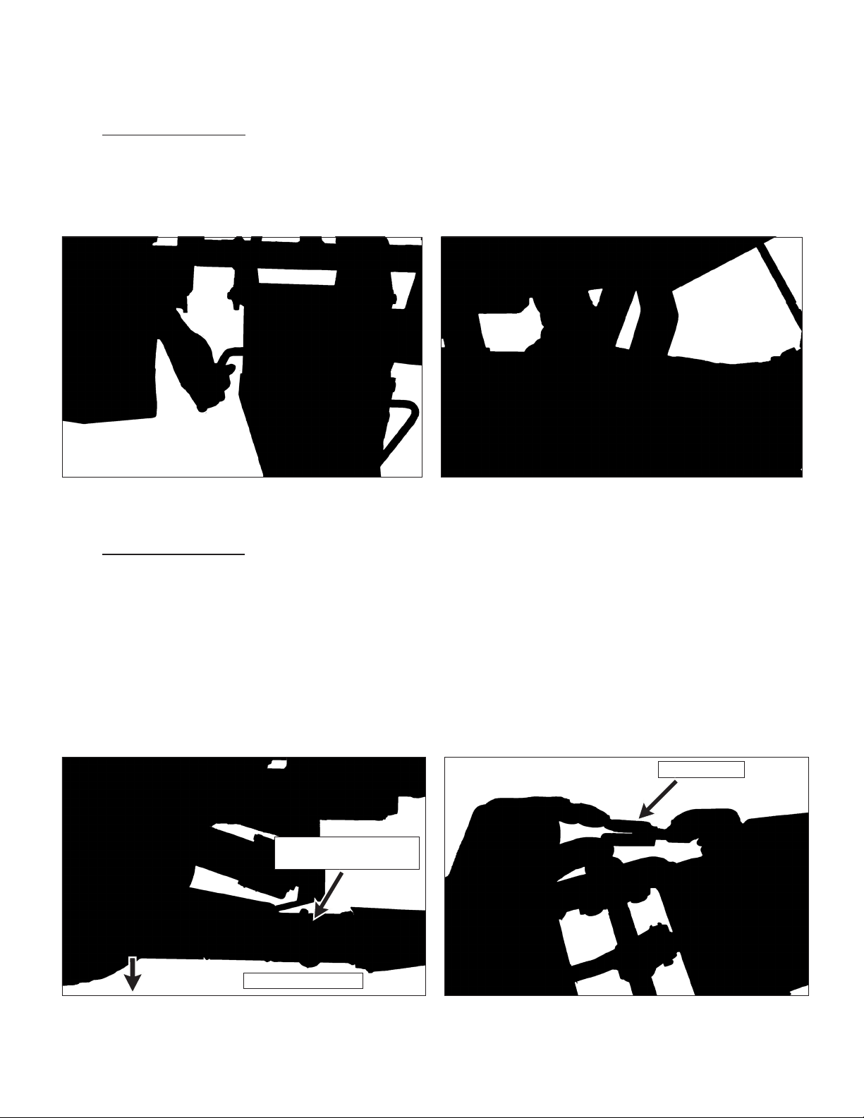
3. Check adjustment of angle stop bolts with blade in the fully angled postion in both
directions (figure 4.1). Confirm foot trigger locking tang engages freely in the angle adjust
slot while the stop bolt is contacting the side of the hitch adapter frame (figure 4.2).
Adjust as necessary.
Locking Tang
Hitch Adapter Frame
Figure 4.1
Angle Stop Bolt
Foot Trigger
Figure 4.2
6
Page 10

Removing Dozer Blade from Tractor
H10 Instructions
1. Lower dozer blade until just touching the ground.
2. Shut o machine and set parking brake.
3. Open PTO shield and remove linch pin from the quick hitch latch.
4. Pull hitch lock lever fully to rear to “UNLOCKED” position.
5. Slide dozer blade o implement hitch, or reverse the tractor out of the attachment.
H19 Instructions
1. Lower dozer blade until just touching the ground.
2. Shut o machine and set parking brake.
3. On the H19 implement hitch, pull the hitch lock lever fully forward to “UNLOCKED”
position.
4. Slide dozer blade o implement hitch, or reverse the tractor out of the attachment.
7
Page 11

Dozer Blade Operation
Warning !
Before operating an implement, become familiar with the location and
function of all operator controls. Knowing the location, function, and
operation of these controls is important for safe and ecient operation.
Lift/Lower blade: The dozer blade may be raised or lowered by operating a toggle switch
located on the Forward Speed Control (FSC) lever.
• Move the switch backward to lift the blade.
• Move the switch forward to lower the blade.
Blade Angle Position
• There are five positions to which the blade can be adjusted:
- Straight forward
- Right/Left 15 degrees
!
- Right/Left 30 degrees
Figure 5.1
Positions
8
Page 12

Dozer Blade Operation
Adjusting Blade Angle
• While o the ground:
- Method 1: Use one foot to hold down the foot trigger (figure 5.2) while
using your other foot to push the blade into the desired position (figure
5.3). Release the foot trigger to allow locking tang to engage into place.
Figure 5.2
Figure 5.3
- Method 2: To swing the blade into position, hold down the foot trigger
(figure 5.4) while turning the tractor using the momentum of the blade to
swing the blade into the desired position and release foot trigger to allow
locking tang to engage into place.
• While on the ground:
- Hold down the foot trigger (figure 5.4) and
turn the machine. While turning right, dozer
blade will pivot left; while turning left, dozer
blade will pivot right. Release the foot trigger
to allow locking tang to engage into place.
Figure 5.4
Extension Spring / Trip Spring
The dozer blade is designed to “trip” forward when striking large rocks, tree stumps,
etc. Once the blade clears the obstacle, the blade will spring back to normal operating
position, eliminating shock to the operator and tractor.
• Adjust the extension spring tension by
holding the eye bolt with pliers and
tightening the ESNA nut (figure 5.5) to
the amount of tension required for safe
operation (a minimum of 2 threads should
protrude through ESNA nut).
Figure 5.5
9
Page 13

Dozer Blade Operation
Trip Lock
Rigid use: When the operator can be absolutely certain there are no rigid obstructions on
the surface (e.g. broken sidewalks, tree roots, stakes, etc.) while using the dozer blade, and
the forward trip action of the blade is NOT required, move the trip lock over the stop rod.
• To engage the trip lock, compress the spring and rotate the trip lock over the
stop rod (figure 6.1). Release pressure on the spring, and place lock over stop
rod (figure 6.2). Be sure the trip lock seats flush on the stop rod. This procedure
“locks” the blade in place and will prevent the forward trip action.
Caution !
!
Using the trip lock is NOT recommended when obstructions can not
be seen (e.g. under snow cover).
Rigid blade operation should only be used with low ground speed.
Engaging Trip Lock
Figure 6.1 Figure 6.2
Trip Lock Engaged
10
Page 14
Maintenance
Maintenance
For maintenance instructions for your tractor, please see the owner’s manual for
your model. If you do not have an owner’s manual, you can download one at
www.walkermowers.com. Select your model, then click on “Downloads”.
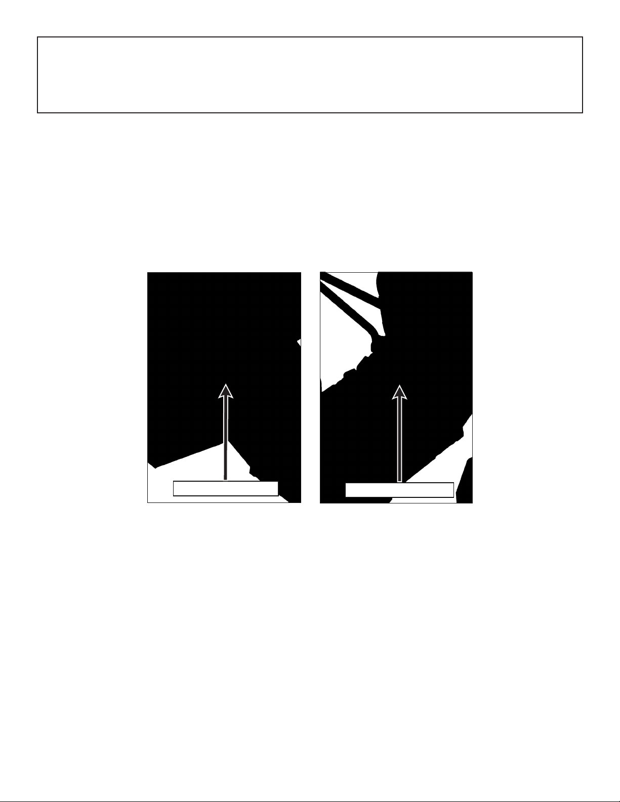
Lubricate the following oil points every 25 hours of operation with SAE 10 oil:
• Blade angle pivot (figure 7.1)
• Foot trigger pivot (figure 7.2)
Blade Angle Pivot
Figure 7.1 Figure 7.2
Check/Adjust hitch lock tension every 8 hours of operation, or as needed. See page 5 for
details.
Foot Trigger Pivot
11
Page 15

Maintenance
Inspect wear strip often (approximately every 2 hours of operation). Upon reaching the
maximum allowable wear (approximately 1/8” remaining as shown in figure 7.3) either
lower wear strip to second row of carriage bolt holes, flip the wear strip, or replace the
wear strip. DO NOT allow the wear strip to become so worn as to cause damage to the
dozer blade.
DO NOT allow wear to
occur above this level
on the wear strip.
Figure 7.3
1/8” minimum
Wear zone. Lower, flip, or
replace wear strip when
both edges are worn.
12
Page 16

48" DOZER BLADE (H11)
ITEM PART DESCRIPTION NO.
NO. NO. REQ’D
Dozer Blade
1 6624-4 Foot Trigger 1
2 6624-12 Torsion Spring 1
3 6624-14 Pivot Shaft (4-7/8) 1
4 6624-9 Foot Trigger Mount 1
5 6624-23 Hitch Adapter 1
6 6624-5 Break Away Lock 1
7 6624-10 Pivot Shaft (18-3/8) 1
8 8401-2 Safety Lockout Spring 2
9 6624-20 Dozer Blade (48") 1
(Includes Items # 11 & 12)
10 6624-18 Wear Strip/Steel 48-1/2" 1
11 5856-1 Decal, Made In USA 1
12 5809-2 Decal, Walker 1
13 6624-3 Blade Mount 1
14 6624-11 Hitch Pin 1
15 6624-13 Extension Spring 1
16 6624-19 Eye Bolt (5/16-18 x 2) 1
ITEM PART DESCRIPTION NO.
NO. NO. REQ’D
Fasteners
F013 3/8-16 Whiz Locknut 3
F016 1/2-13 Self-Locking Nut 1
F020 5/16-18 ESNA Nut 7
F039 3/8-16 x 1-1/4 Hex Bolt 2
F111 1/8 x 3/4 Cotter Pin 2
F151 3/8-16 x 7/8 Hex Bolt 3
F336 3/8-16 Jam Nut 4
F420 5/16-18 x 1-1/4 Carriage Bolt 6
F436 3/16 x 1-1/8 Spring Pin 1
F481 Washer 5/16 x 7/8 x .125 1
F521 Roll Pin 1/4 x 1 1
13
Page 17

8
6
7
F436
9
10
1
2
F111
3
16
15
14
F521
13
12
11
4
5
F151
F020
F481
F013
F016
F039
F336
F336
5809-2
F020
F420
48" DOZER BLADE (H11)
14
Page 18

60" DOZER BLADE (H16)
ITEM PART DESCRIPTION NO.
NO. NO. REQ’D
Dozer Blade
1 6624-4 Foot Trigger 1
2 6624-12 Torsion Spring 1
3 6624-14 Pivot Shaft (4-7/8) 1
4 6624-9 Foot Trigger Mount 1
5 6624-23 Hitch Adapter 1
6 6624-5 Break Away Lock 1
7 6624-10 Pivot Shaft (18-3/8) 1
8 8401-2 Safety Lockout Spring 2
9 6624-58 Dozer Blade (60") 1
(Includes Items # 11 & 12)
10 6624-46 Wear Strip (60") 1
11 5856-1 Decal, Made In USA 1
12 5809-2 Decal, Walker 1
13 6624-3 Blade Mount 1
14 6624-11 Hitch Pin 1
15 6624-13 Extension Spring 1
16 6624-19 Eye Bolt (5/16-18 x 2) 1
ITEM PART DESCRIPTION NO.
NO. NO. REQ’D
Fasteners
F013 3/8-16 Whiz Locknut 3
F016 1/2-13 Self-Locking Nut 1
F020 5/16-18 ESNA Nut 9
F039 3/8-16 x 1-1/4 Hex Bolt 2
F111 1/8 x 3/4 Cotter Pin 2
F151 3/8-16 x 7/8 Hex Bolt 3
F336 3/8-16 Jam Nut 4
F420 5/16-18 x 1-1/4 Carriage Bolt 8
F436 3/16 x 1-1/8 Spring Pin 1
F481 Washer 5/16 x 7/8 x .125 1
F521 Roll Pin 1/4 x 1 1
15
Page 19

60" DOZER BLADE (H16)
1
F111
F151
2
16
11
15
3
4
5
10
F020
F481
5809-2
12
F420
13
F016
F336
8
F521
14
F039
F336
F013
6
7
F436
9
F020
16
Page 20

OPERATOR’S NOTES
17
Page 21

OPERATOR’S NOTES
18
Page 22

OPERATOR’S NOTES
19
Page 23

LIMITED WARRANTY
FOR
WALKER DOZER BLADES
1.
2.
3.
What this warranty covers, and for how long:
Walker Manufacturing company will, at its option, repair or replace, without charge, any part covered
by this warranty which is found to be defective in material and/or workmanship within one (1) year*
after date of sale to the original retail purchaser unless the product is used for rental purposes,
in which case this warranty is limited to ninety (90) days. At Walker’s request, customer will make
the defective part available for inspection by Walker and/or return the defective part to Walker,
transportation charges prepaid. All parts and components of the Walker Dozer Blade are covered by
this warranty.
What this warranty does not cover:
A. This warranty does not cover defects caused by depreciation or damage caused by normal wear,
accidents, improper maintenance, improper use or abuse of the product, alterations, or failure to
follow the instructions contained in the Operator’s Manual for operation and maintenance.
B. The customer shall pay any charges for making service calls and/or for transporting the attachment
to and from the place where the inspection and/or warranty work is performed.
How to obtain service under this warranty:
Warranty service can be arranged by contacting the dealer where you purchased the machine or by
contacting Walker Manufacturing Company, 5925 East Harmony Road, Ft. Collins, CO 80528. Proof
of the date of purchase may be required to verify warranty coverage.
4.
Warranty limitation:
A. THERE IS NO OTHER EXPRESS WARRANTY. ANY WARRANTY THAT MAY BE IMPLIED FROM
THIS PURCHASE INCLUDING MERCHANTABILITY AND FITNESS FOR A PARTICULAR PURPOSE IS
HEREBY LIMITED TO THE DURATION OF THIS WARRANTY AND TO THE EXTENT PERMITTED BY
LAW ANY AND ALL IMPLIED WARRANTIES ARE EXCLUDED. Some states do not allow limitations on
how long an implied warranty lasts, so the above limitations may not apply to you.
B. WALKER WILL NOT BE LIABLE FOR ANY INCIDENTAL, CONSEQUENTIAL, OR SPECIAL DAMAGES
AND/OR EXPENSES IN CONNECTION WITH THE PURCHASE OR USE OF THE Machine. Some
states do not allow the exclusion or limitation of incidental or consequential damages, so the above
limitation(s) or exclusion(s) may not apply to you.
C. Only the warranty expressed in this limited warranty shall apply and no dealer, distributor, or
individual is authorized to amend, modify, or extend this warranty in any way. Accordingly, additional
statements such as dealer advertising or presentations, whether oral or written, do not constitute
warranties by Walker, and should not be relied upon.
D. This warranty gives you specific legal rights, and you may also have other rights which vary from
state to state.
20
Page 24

WALKER MFG. CO. 5925 HARMONY ROAD, FORT COLLINS, CO. 80528 - (970)221-5614
FORM NO. 011116
PRINTED IN USA
 Loading...