

Page 1
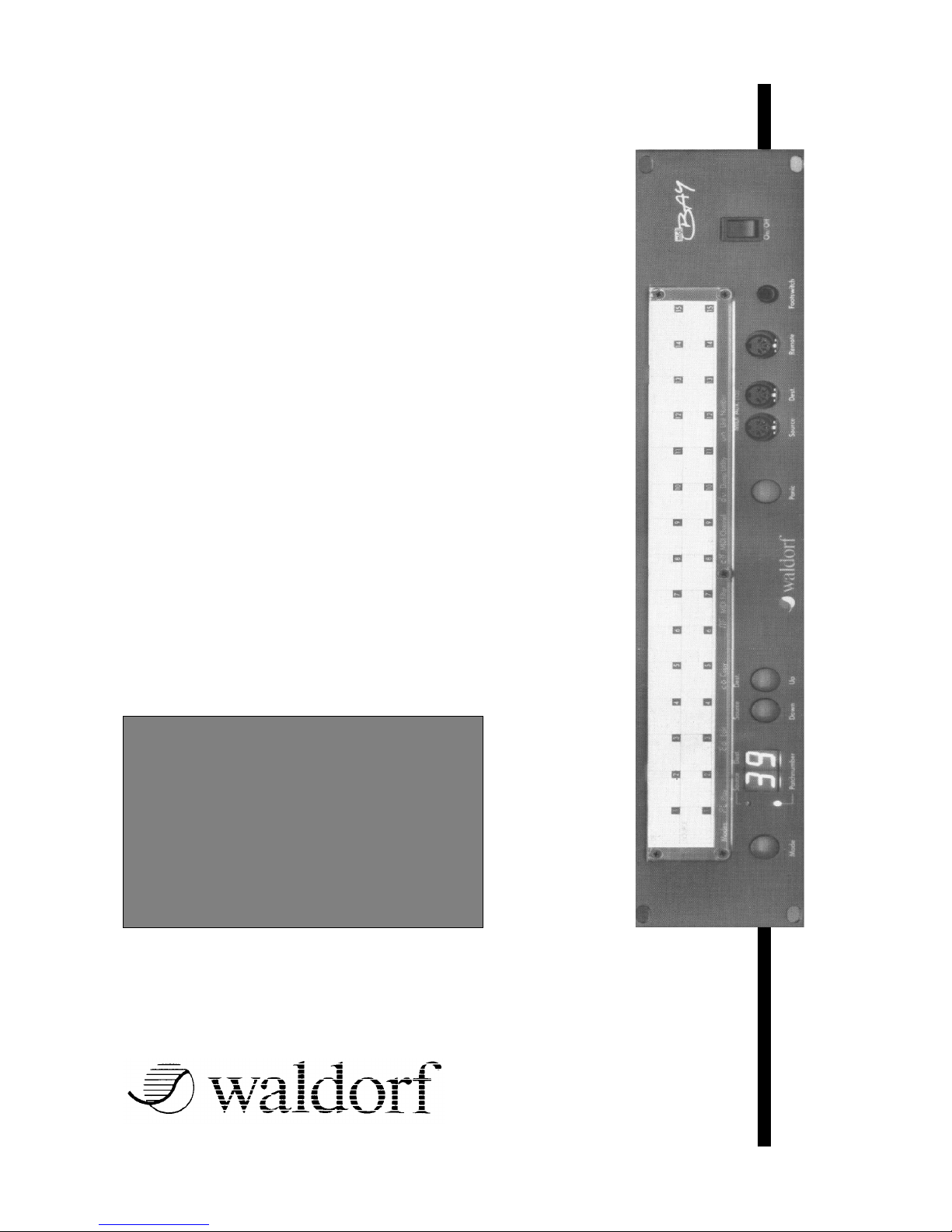
MIDI BAY
MIDI BAY
Manual
This manual is a quite accurate copy of the original manual. A guy
from Waldorf was so kind to send it to me before Waldorf left the
market. I scanned, OCR´d and worked it over. I tried to reproduce
everything as original as possible. I only corrected some minor
mistakes in writing, left out the blank pages and so on.
I did it without any financial interest. If you´re happy that you´ve found
it please think about if there is something that you can do for the rest of
the world. ;-)
Regards,
Lars
12/13/04
Page 2

Table Of Contents
Table Of Contents
1. Warranty 01-0
2. Scope of Supply 01-1
3. Technical Remarks 01-1
4. Preface 04-1
5. How It Works 05-1
6. Controls 06-1
7. Installation 07-1
8. Operation Modes 08-1
9. Creating and Editing Programs 09-1
1.
1. The Merge Function 09-4
2. The Merge Filter 09-8
10.Selecting Programs 10-1
11.The Panic-Key 11-1
12.Copying Programs 1 2-1
13.The Dump Function 13-1
Changing the Unit-ID 13-2
14. Assignment List 14-1
15. MIDI Implementation 15-1
16.Specifications 16-1
MIDI BAY Manual
Page 3

1. General
1. General
Warranty
Waldorf Electronics warrants the MIDI BAY for a period
of 6 months. This applies solely to flaws in material.
Any claims can be made within this period only.
Damages, consequential damages and cost directly or
indirectly resulting from use of this product or product
failure are not covered by the warranty.
Scope of Supply
Prior to initial operation of the unit, please check the
contents of this package for completeness and perfect
condition.
MIDI BAY Owner's
Manual
Technical Remarks
Only high-grade and tested components have been
used for the construction of the MIDI BAY. When
putting the unit into operation, the general guidelines
for operating electrical or electronical devices must
always be observed. In order to avoid lengthy and
expensive repairs you should give the MIDI BAY the
same care and attention you give the remaining
components of your MIDI system.
In particular, you should ensure that...
• the MIDI BAY is never exposed to strong vibrations,
dust or extreme humidity.
• the correct mains voltage is selected and that nothing
but the power cords and MIDI cables intended for
this application are used.
MIDI BAY Manual
Page 4

4. Preface
4. Preface
Dear Customer,
thank you for purchasing the MIDI BAY. This product
from Waldorf Electronics is an extremely powerful and
easy-to-use MIDI processor which will facilitate the use
of your MIDI system and will considerably enhance the
system's efficiency.
Perhaps you are already familiar with patchbay
concepts from audio systems. Here, mechanical
patchbays and - recently - also larger. MIDIfied units
make life easier for sound engineers and musicians.
Probably, you have never worked with a patchbay
before. If so, we recommend you to read the entire
manual thoroughly - since the MIDI BAY offers a
greater scope of possibilities than a conventional audio
patchbay.
Specific information in this manual is always presented
in the same way.
whenever we refer to the MIDI BAY's controls or
connectors, the corresponding designations are
given in square brackets:
Connector [Source 1], [Mode] key
designations on the front of the MIDI BAY and
display messages are given in "arrow" brackets:
<MIDI AUX>, <Ed>
the MIDI BAY's display is represented as follows:
MIDI BAY Manual
Page 5

4. Preface
4. Preface
"step-by-step" instructions appear as follows:
● take the owner's manual.
● read one word after the other.
additional remarks or remarks of special importance
are marked by an arrow.
➔ "maybe you should turn the unit on before using it!"
Please enjoy working with the MIDI BAY.
MIDI BAY Manual
Page 6

5. How It Works
5. How It Works
How It Works
If you own several MIDI devices - probably some of
them sending and receiving data on several MIDI
channels - you're probably vexed regularly because the
connection cables have to be rearranged all the time:
when controlling several sound expanders from one
keyboard, you would like to control the same expanders
by the sequencer and play along on a second
keyboard. Maybe you would like to trigger your sampler
from a MIDI drum kit and subsequently load sample
data into your computer...
All of these jobs require different cabling - this needs a
lot of time and stresses the mechanically unsafe 5-pin
DIN connectors excessively. And it is even more
frustrating to leave the MIDI cabling as it is. thus
possibly restricting both performance and potential of
the instruments.
Today, with even small homerecording studios
integrating several keyboards, possibly MIDI drum pads
and various sound generators, these problems multiply
-the system becomes badly arranged and unreliable.
In such a situation, the MIDI BAY is the optimum
solution. It enables you to quickly set up even a
complex MIDI system and to get it reliably under
control. Flexibility is not restricted anymore: 15 freely
programmable inputs and outputs each allow for
individual solutions. Furthermore, a merge function
provides mixing of two MIDI data packages, thus
multiplying the system's capabilities both live on stage
as well as if operated with a sequencer.
Let's take a closer look at how the MIDI BAY works:
MIDI BAY Manual
Page 7
5. How It Works
5. How It Works
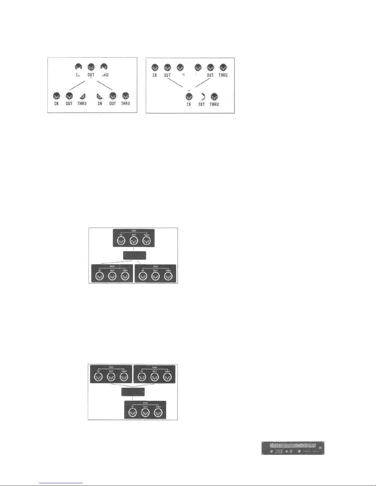
The MIDI specification determines that one MIDI
OUT is assigned to each MIDI IN. However, if you
want to transmit one MIDI signal to several
instruments, there are exactly two ways to do so:
either you connect these instruments to each
other via their MIDI THRU connectors (already
with three units this might lead to signal delay and
deformation), or you use a device that is able to
split up a MIDI signal and send it to several MIDI
OUT connectors at the same time.
Now, if you want to have one MIDI device
controlled by two instruments simultaneously, you
need a device that is able to mix two MIDI signal
packages. A simple two-way adapter, as is often
used for audio connections, cannot be used here
because MIDI signals are digital signals and for
merging them a special processor is required.
MIDI BAY Manual
Page 8

5. How It Works
5. How It Works
The MIDI BAY integrates both functions - copying and
merging MIDI signals - and additionally offers the
possibility of programming any "set" of inputs and
outputs, and of selecting them at the touch of a key or
with a MIDI instruction, at any time.
MIDI BAY Manual
Page 9

6. Controls
6. Controls
Controls
The MIDI BAY features the following controls and
female connectors:
The upper portion of the front panel is reserved for the
assignment list. The two notches on the plexiglass
frame serve for pulling out the assignment list. Entering
the connected units in that list will facilitate setting up of
MIDI BAY programs.
Below the frame there is the [Mode] key which selects
one of the seven operation modes the MIDI BAY
provides. These operation modes will be dealt with in
the next chapter.
Close to the Mode key you will find a double-digit
display which indicates current data and information.
Since the MIDI BAY features such a clearly arranged
design and concept, and since you will mostly call up
patch programs, a double-digit display will provide
enough information and allow for convenient working
with the unit.
The two LEDs close to the display tell you whether the
MIDI BAY is in Play Mode or Edit Mode.
The [Up] and [Down] keys increase or decrease the
value currently indicated by the display. This will be
either the program number, the MIDI channel or the
Unit-ID.
In case of hanging notes or seriously "detuned"
instruments, the [Panic] key - as the name implies
-serves for muting the connected units and setting them
to a defined starting point. Anybody who has been
tormented by hanging notes in a critical situation will
appreciate this function.
➔ normally, you will communicate with the MIDI BAY
via the controls described above. However, the unit
may also be programmed using an editor program
for the ATARI ST computer or the remote control
available as a seperate accessory.
MIDI BAY Manual
Page 10

6. Controls
6. Controls
The front panel of the MIDI BAY also accomodates four
connectors:
<MIDI Aux.> offers two MIDI connectors that are
identical to the connectors [Source 15] and [Destination
15] on the rear. The MIDI IN connector on the front has
priority: as soon as you hook up a MIDI instrument
here, the corresponding MIDI IN connector on the rear
is switched off. Thus, you may "loop in" additional units
(for instance, your friend's remote keyboard and/or a
new sound expander) into your system without having
to use the connectors on the rear of the MIDI BAY.
The [Remote] jack is for connecting of the optional
remote control MBR-1 With this unit all functions of the
MIDI BAY can be performed even over greater
distances - an advantage not to be underestimated,
especially in the studio or on stage. Although this is a 5pos. connector, this is not a MIDI connector and you
should never try to insert a MIDI cable here!
Connect a conventional foot switch via the [footswitch]
jack. With this switch you can switch over between
MIDI BAY programs which will also facilitate your work
-especially in live situations where two different setups
must be rapidly accessible!
Before we forget... of course an [On/Offj switch can be
found as well!
➔ While we're at it, we would like to mention that you
have to switch on the MIDI BAY before you turn on
the receiving units connected.
On the rear of the MIDI BAY you will find a fairly high
number of inputs and outputs: on the whole, 75
[Source] and 15 [Destination] connectors are waiting for
you to hook up your instruments, computer(s) and
controllers.
Furthermore, the fuse holder can be found on the rear.
➔
if the fuse has blown, only replace it by a fuse of the
same type and rating! Otherwise, you run the risk of
damaging your MIDI BAY badly ... additionally, this will
void the warranty!
MIDI BAY Manual
Page 11

7. Installation
7. Installation
Installation
● set up the MIDI BAY at a place where it is not
exposed to strong vibrations, dust or extreme
humidity. Connect the unit to the mains.
➔ the MIDI BAY may also be installed within a 19"
rack. The required bolts are not enclosed.
● now connect the MIDI OUT jacks of all units
transmitting MIDI signals (master keyboards, MIDI
drum pads and guitar control lers, synthesizers,
samplers, etc.) to the [Source] connectors of the
MIDI BAY.
Please observe the following:
If you use the merge function, the signals from [Source
1] and from an additional, freely selectable [Source]
connector will be mixed. Furthermore, you can send
program change instructions to the MIDI BAY via
[Source 1]. Therefore, your master instrument, or your
computer respectively, the data of which you want to
merge with the data coming from other MIDI units, must
be connected to [Source 1].
● now connect the [Destination] jack of the MIDI BAY
to the MIDI IN connectors of all units/instruments you
want to control. For reasons of clearness, we
recommend you to connect all units that
communicate in both directions with the MIDI BAY to
connectors with identical numbers.
Now you may start "patching", i.e. start programming
the MIDI connections.
MIDI BAY Manual
Page 12
8. Operation Modes
8. Operation Modes
Operation Modes
The MIDI BAY places seven different operation modes,
or function levels, at your disposal. Switch over between
the individual modes using the [Mode] key. At each key
press the unit changes to the level "next in rank".
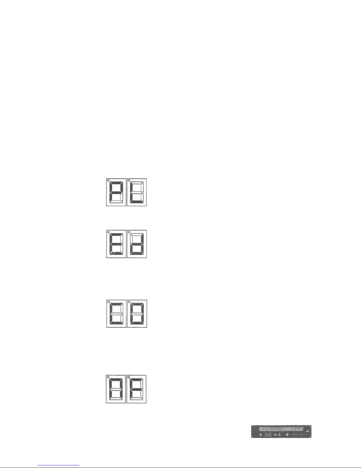
● the selected operation modes after each key press
will be temporarily indicated by two letters appearing
in the display.
In Play Mode you can call up the stored MIDI BAY
programs.
In Edit Mode you can modify one of the 99 programs.
The Copy Mode allows for copying programs from one
memory location to another.
The Merge Filter Mode serves for programming the 5
data filter which may be placed in front of the inputs
when using the merge function.
MIDI BAY Manual
Page 13
8. Operation Modes
8. Operation Modes
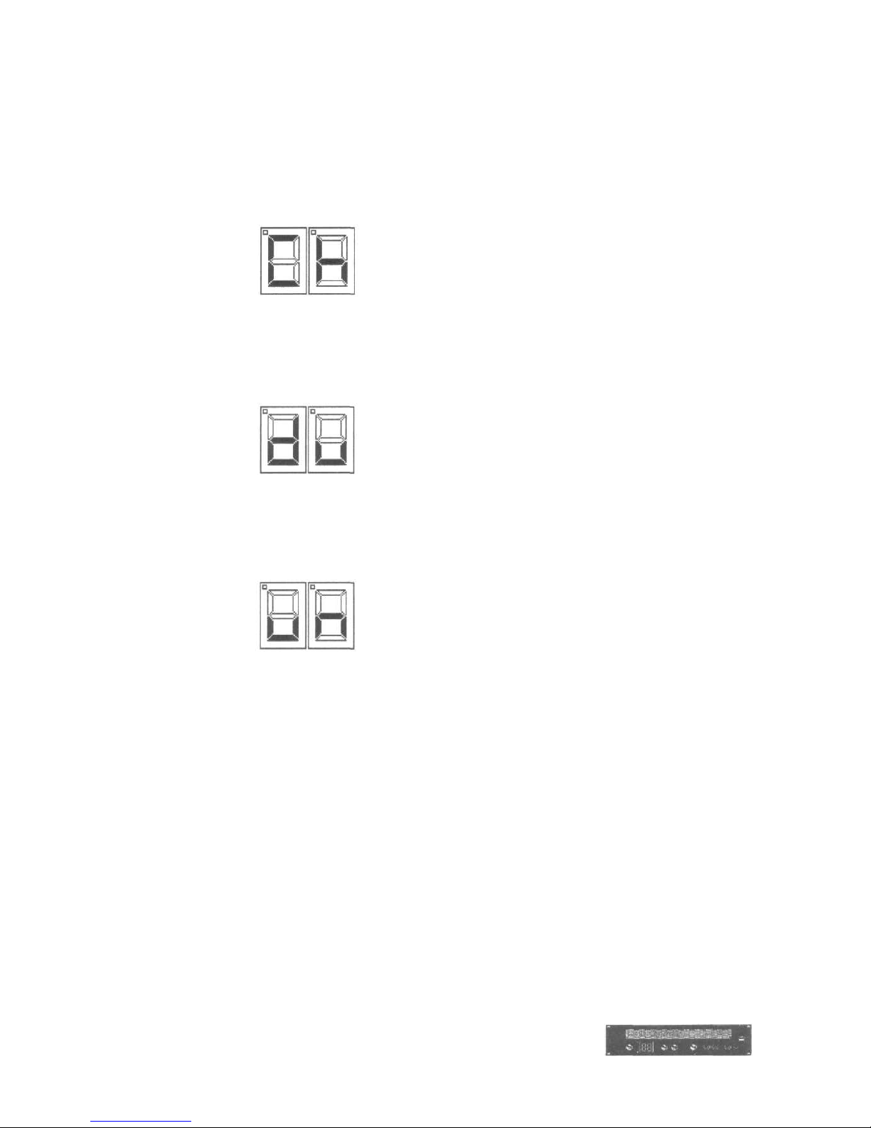
In Channel Mode, the MIDI channel on which the MIDI
BAY receives program change instructions can be
adjusted.
Activate the DUMP Mode to send the MIDI BAY's entire
memory contents (the 99 programs) via MIDI - at the
simple touch of a button.
Finally, in Unit Mode, you can determine the MIDI
BAY's unit number in order to ensure correct sending
and receiving of program data.
(In the following, we will not keep to the order above,
but present you the individual functions and function
levels just as you are most likely to need them).
MIDI BAY Manual
Page 14
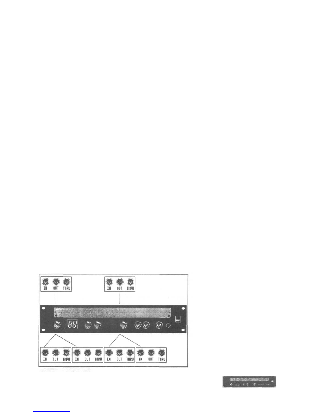
9. Creating Programs
9. Creating Programs
Creating and Editing Programs
● switch on the MIDI BAY.
Now the unit is in PLAY Mode: the display indicates the
number of the selected program memory location, the
green "Play Mode" LED is lit.
● using the [Up] and [Down] keys, select the program
memory location on which you want to store your
new program.
The program memory locations are numbered 1
through 99.
● having selected the desired memory location, change
to the EDIT mode by depressing the MODE key
once. The display temporarily indicates the message
<Ed> to inform you about the operation mode
change, now the red "EDIT Mode" LED is lit instead
of the green one.
Creating MIDI BAY programs is really easy: you just
have to assign a [Source] connector to each
[Destination] connector. This procedure has the
advantage that any [Source] connector (i.e., a signal)
can be assigned to several outputs without any
difficulties. By assigning two or more outputs each to
the same input, you can thus set up the MIDI BAY in
such a way that it acts like several "distributors",
independently of each other.
MIDI BAY Manual
Page 15
9. Creating Programs
9. Creating Programs
However, it will be most useful to program a simple
standard configuration before.
● select memory location #1 - as described above -
and activate the EDIT Mode.
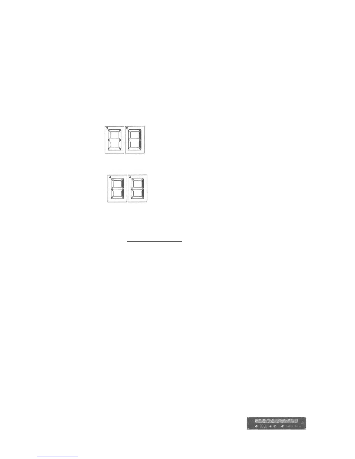
The display changes from
to
When using this kind of representation, the right display
half shows the selected [Destination] connector and the
left display half the assigned [Source] connector.
● now, first of all, use the [Up] key to select the desired
[Destination] connector. A small dot in the right upper
corner of the display indicates the tens, i.e., MIDI
connectors #1 to #9 are represented as usual,
connector #10 is displayed as <.O>, connector #11
as <.1>, etc. You will soon get familiar with this kind
of representation.
● using the [Down] key, select the [Source] connector
you want to assign to this output.
● then change to the next (used) [Destination]
connector and repeat the procedure.
Apart from the messages for connectors 1 through 15,
there is the message "M" which serves for programming
the merge function. We will deal with this function in
chapter 9.1.
MIDI BAY Manual
Page 16

9. Creating Programs
9. Creating Programs
➔ all changes are accepted immediately. So you can
check - while running the sequencer or playing on
your master keyboard - whether the desired
connection has actually been established. Of course,
you should also observe that both sending and
receiving units are set to the same MIDI channel.
● having finished a program, briefly hit the [Mode] key
once. The new program will be stored automatically
and the MIDI BAY will return to the PLAY Mode.
Please note that the MIDI BAY does not feature a
seperate STORE function. As soon as you leave the
EDIT Mode (via the [Mode] key), the modifications
made will be stored, the original program will be
overwritten, i.e. deleted. If you do not want to store the
changes you made, i.e., retain the original program,
leave the EDIT mode by depressing the [Panic] key
once.
MIDI BAY Manual
Page 17
9.1 The Merge Function
9.1 The Merge Function
The Merge Function
As you have already noticed, you may not only send
one MIDI data package to several connectors
simultaneously, but you may also combine two data
packages and subsequently send them to one or
several outputs. This is called merging, the function is
called merge function or merger.
Generally, the MIDI BAY's merger always combines the
data from the unit connected to [Source 1] and the data
from another unit. Therefore, when programming the
merge function, you just have to determine the second
<Source> connector.
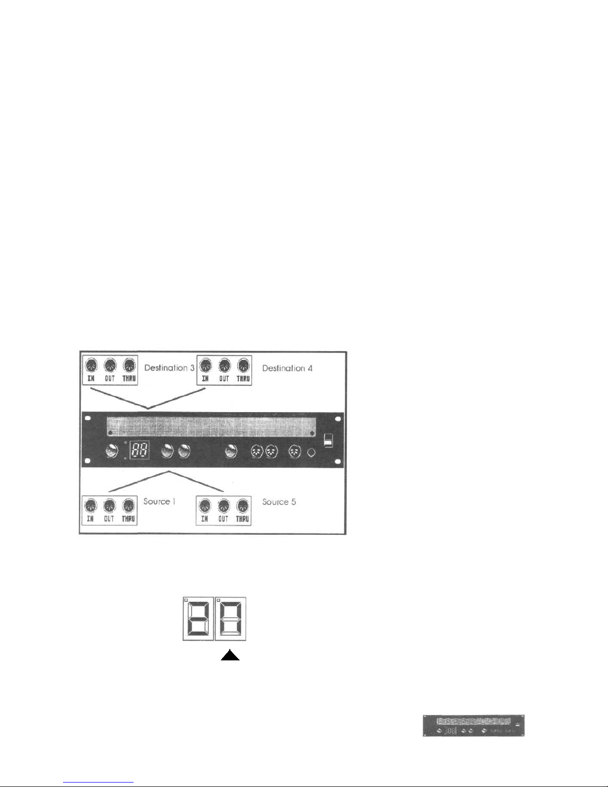
Supposed you want to merge the data from [Source 1]
and [Source 5], and output them via [Destination 3] and
[Destination 4].
● depress the [Up] key until the second digit of the
display reads an <M> (which stands for "Merge").
MIDI BAY Manual
Page 18

9.1 The Merge Function
9.1 The Merge Function
● using the [Down] key. select connector [Source 5].
Thus, [Source 5] is defined as second merger input.
Now, you just have to determine to which [Destination]
connector(s) the data shall be routed. Proceed as
follows:
● using the [Up] key, select connector [Destination 3].
● depress the [Down] key until the first display digit
reads <M>.
● repeat this procedure for connector [Destination 4].
As you can see, this function opens up enormous
possibilities: for instance, MIDI information can be
recorded simultaneously by a computer and can be
sent to the desired expanders without having to use the
"Soft Thru" function of the sequencer.
Additional flexibility can be achieved by assigning the
original data of the two merger inputs to seperate
[Destination] connectors. For instance - to continue the
example mentioned above - two keyboard players could
control one expander rack, but only the infomation
coming from one keyboard would be recorded by the
sequencer.
➔ if you own a lot of different controllers, you might
wish to freely select both merger inputs With a little
trick, this can be accomplished as follows:
Connect the [Destination] jack you currently do not
need to [Source 1].
Now the signal routed to this [Destination] connector is
led to the merger's input #1. To merge the signals
MIDI BAY Manual
Page 19

9.1 The Merge Function
9.1 The Merge Function
coming from any two [Sources], simply change this
connector's assignment.
The only disadvantage of this procedure is that now you
only have 14 inputs and outputs at your disposal.
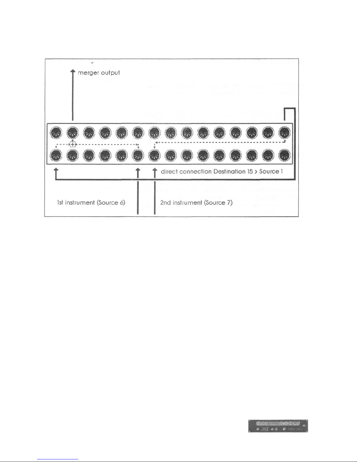
Another example to clarify the facts:
● connect [Destination 15] to [Source 1] via a short
MIDI cable.
Supposed you want to merge [Source 6] and [Source 7]
and route them to [Destination 2].
● change to EDIT mode by depressing the [Mode] key.
● using the [Up] key, select [Destination 15]. Assign
input [Source 7] to this output.
● depress the [Up] key once again, the second display
digit reads <M>. Depress the [Down] key until the
first display digit reads <6>.
What the MIDI BAY doesn't see, the processor won't
grieve over... by connecting [Destination 15] to [Source
1], the data will be rerouted from [Source 7] to [Source
1]. From there, it can be merged with the data coming
from [Source 6] without any problems.
● depress the [Up] key until the second display digit
reads <2>. Select <M> with the [Down] key, thus,
you have defined [Destination 2] as output for the
merged data. That's it...
The following illustration will clarify this
fairly sophisticated configuration.
MIDI BAY Manual
Page 20
9.1 The Merge Function
9.1 The Merge Function
MIDI BAY Manual
Page 21

9.2 The Merge Filter
9.2 The Merge Filter
The Merge Filter
Merging MIDI signals leads to specific problems, above
all if "system overlapping" messages are concerned.
For instance. ROLAND keyboards send the MIDI
message "All Notes Off" as soon as all keys are
released, which switches off all notes played.
Normally, this is to be welcomed, or at least it doesn't
matter, since all notes must be muted after releasing
the keys.
However, if two keyboard players control one expander,
all notes played by one player will be cut off as soon as
the other keyboard player releases the keys on his
keyboard. Also merging different types of data might
lead to problems.
Therefore, the MIDI BAY uses a merge filter which
fades out critical data types - individually for both
merger inputs.
The various filters are programmed in the Merge Filter
Mode which can be activated by depressing the [Mode]
key three times.
Using the [Down] key you may now select the individual
filters. The display reads the corresponding
abbreviations while the two decimal points indicate the
filter status of the two merger inputs. This means: if the
decimal point is lit, the MIDI data can pass through the
filter without restriction. If the decimal point is not lit, the
data is filtered out. The left decimal point is effective on
the first merger input (i.e., connector [Source 1]), the
right decimal point refers to the second merger input.
Use the [Up] key to activate the filter for the desired
input(s).
MIDI BAY Manual
Page 22

9.2 The Merge Filter
9.2 The Merge Filter
The following types of data may be filtered out:
<cM> Channel Mode Messages are special controller
messages and are used to set MIDI instruments
to certain operation modes. Furthermore, they
mute all voices sounding at the moment. To
avoid unpleasant results - described at the
beginning of this section - they should be
filtered out.
<Ao> Controller #123 is the "famous" All-Notes-Off
message. Normally, it will be sufficient to filter
out this mode message.
<Sr> System Real-Time Messages are used to
synchronize the entire MIDI system. It will
hardly happen that two MIDI devices send
contradicting Real-Time Messages, however,
this might occur - for instance, if the data from a
sequencer and from a drum computer is
merged. If so, at least the Real-Time Messages
sent by one unit should be filtered out.
<cL> The MIDI Clock is one portion of the real-time
messages mentionend above; like a
metronome it determines the tempo of the
sequencer, drum computer, arpeggiators. etc.
hooked up to the system. Of course, only one
tempo can be used. Therefore, you should use
the MIDI clock filter to prevent anything but the
master's tempo information (in general, this is
your sequencer) from reaching the merger
output.
<rS> This filter differs from the remaining filter types
in that it does not filter incoming data but
influences outputting of the already merged
data.
The Running Status is a process used for
compact transmission of MIDI data, for several
consecutive notes, the "Note On" status byte is
sent only once.
However, this process has not been part of the
original MIDI standard. Therefore, if you are
encountering problems with older synthesizers,
MIDI BAY Manual
Page 23

9.2 The Merge Filter
9.2 The Merge Filter
switch off the Running Status for the merger
output. Simply depress the [Up] key.
Having effected all settings as desired, you may return
to the Play Mode by depressing the [Mode] key.
However, if you do not want to store the changes you
made, leave the Merge Filter Mode by hitting the [Panic]
key.
● the Merge Filter parameters may be set
individually for each patch.
MIDI BAY Manual
Page 24

10. Selecting Programs
10. Selecting Programs
Selecting Programs
There are three ways to switch over between the
programs of the MIDI BAY. The unit must always be in
PLAY Mode.
Changing programs on the unit:
use the [Up] and [Down] keys to select a MIDI BAY
program.
Changing programs via foot switch:
especially in live situations, you often need a "third
hand" to select a new program. With the help of a
simple foot switch - also used as sustain pedal on most
synthesizers -you may advance the MIDI BAY from one
program to the next one.
Connect such a foot switch to the [Footswitch] jack of
the MIDI BAY and place it in such a way that you will
not get it confused with the sustain pedal. It would be
exasperating if you want to keep a chord but would
'choke off your entire MIDI system.
➔ use the MIDI BAY's COPY function (see chapter
12) to arrange the individual programs in a
reasonable order for live performances.
Changing programs via MIDI:
you may also send a program change instruction from
another MIDI device to the MIDI BAY. For this purpose,
set the MIDI BAY to the channel on which these
instructions are sent.
● depress the [Mode] key four times to activate the
CHANNEL Mode.
● using the [Up] and [Down] keys, you can then adjust
the receive channel for the program change
instructions. Apart from channels 1 through 16 you
may also use the <oF> setting which will block any
program change instruction.
MIDI BAY Manual
Page 25

10. Selecting Programs
10. Selecting Programs
➔ please note that when changing the configuration
while playing, you might also change the assignment
of a certain [Destination] connector, even if notes are
still played. To avoid hanging notes, an "All Notes
Off" message is sent to all connectors when
changing programs. So, always remember that you
will mute all currently played notes when switching
over to another patch.
MIDI BAY Manual
Page 26

11. The Panic Key
11. The Panic Key
The PANIC Key
Hanging notes are not as usual as you would suppose
when reading relevant articles, leaflets and brochures,
however, if they occur they are always good for a largescale panic.
There are two reasons for hanging notes: due to a
(mechanical) interruption of the MIDI connection while
some notes are still on, or due to a certain instrument
'swallowing' a Note Off message.
In the former case, even the most sophisticated panic
function is no help: a cable leading to nowhere will not
effectively transmit reasonable instructions. However,
hanging notes of this kind are blocked on many
instruments by means of an "Active Sensing" function
which "recognizes" the interrupted connection and
sends an All-Notes-Off instructions of its own.
In the latter case - which is more likely to happen - the
[Panic] key of the MIDI BAY is an effective remedy.
Such an error occurs if...
• the sending unit transmits less Note-Off than Note-
On messages (for instance, sequencer malfunction).
• the MIDI interface is overloaded, or if
• the receiving unit does not "pay attention",
i.e., produces a failure due to its own processor
being overloaded.
It is no less annoying if controller data are lost due to
this error, for instance, if the connected expander
"believes" that the Pitch Bend or Modulation Wheels
are still used, although they have been returned to their
center or starting positions. Extremely detuned sounds
and absurd modulation effects are the result.
In any of these cases, the MIDI BAY's [Panic] key sorts
everything out. Two different "panic levels" are at your
disposal, to be reached by depressing the key ....
MIDI BAY Manual
Page 27

11. The Panic Key
11. The Panic Key
If you just hit the [Panic] key. the following instructions are
sent to all [Destination] jacks;
• All Notes Off
• Sustain Pedal Off
• Mod Wheel Off
• Pitch Wheel 64 (center position)
If you depress the [Panic] key for more than one second,
the HyperPanic function will be triggered. The MIDI BAY
transmits:
• Reset All Controllers
• After Touch 0
• Note Off (for all 127 notes on all 16 MIDI channels)
• Note On with velocity 0 (for all 127 notes on all 16 MIDI
channels)
As you can easily figure out, this function triggers more
than 30,000 MIDI instructions - which, of course, needs
some time. The display will read the currently processed
MIDI channel.
MIDI BAY Manual
Page 28

12. Copying Programs
12. Copying Programs
Copying Programs
Every now and then, you might wish to copy a MIDI BAY
program from one memory location to another.
Especially, if you need an already existing program a
second time, in a slightly changed version, this function
will be very useful.
Copying programs is very easy:
● first of all, select in PLAY Mode the program you want
to copy - as described in chapter 10.
● activate the COPY mode by depressing the [Mode]
key twice.
● now determine the memory location you want to copy
the program to. Use the [Up] and [Down] keys. The
green "PLAY" Mode LED will start blinking: remember
that the original program stored at the
target memory location will be deleted by this
function.
● depressing the Mode key once again will start the
copy process, the unit returns to the PLAY mode.
After copying is completed, the copied program will be
recalled automatically. Thus, you can instantly start
editing it in the EDIT Mode.
● if you want to cancel the copy process, leave this
mode by hitting the [Panic] key.
MIDI BAY Manual
Page 29

13. The Dump Function
13. The Dump Function
The Dump Function
Like any other advanced MIDI device, the MIDI BAY
offers the possibility of transmitting your program data
as a so-called Sys Ex Dump via MIDI, of course, Sys Ex
data may also be received.
On the one hand, this means that you can also program
the MIDI BAY via an external editor.
On the other hand, this means that individual programs
or the entire memory contents can be exchanged
between two MIDI BAYs or one MIDI BAY and a
computer. Thus, you can, for instance, store the
required MIDI BAY configuration as part of a sequencer
song.
There are two ways to transmit Sys Ex dumps: either...
• another MIDI device sends a so-called request
instruction which requests the required data.
Normally, this device is a computer with the
corresponding software - for example,
STEINBERG'S Satellite which is included in the
CUBASE sequencer and is well suited for this job.
Or...
• you trigger the data dump on the MIDI BAY yourself.
Proceed as follows:
● depress the [Mode] key five times to activate the
DUMP mode.
● with the [Down] key, you can determine whether the
MIDI BAY is to send the data of all programs (display
reads <Ad> meaning "All Dump") or the data of the
qurrently activated program (display reads
<Pd> meaning "Patch Dump").
● depress the [Up] key and the Sys Ex data will be sent
via all [Destination] connectors.
MIDI BAY Manual
Page 30

13.1 Changing The Unit ID
13.1 Changing The Unit ID
Changing the Unit ID
If you own a VERY extensive MIDI system you might
also have two or even more MIDI BAYs. In this case, it
will also be possible to send Sys Ex data to one of
these MIDI BAYs only. This is done with the "Unit ID"
feature. This is a designation to be adjusted in the UNIT
mode. The MIDI BAY will place this designation before
each Sys Ex dump and will only receive and process
Sys Ex data that have the same designation.
● depress the [Mode] key six times to activate the UNIT
mode.
● using the [Up] and [Down] keys, adjust the desired
Unit ID. Any value from 1 to 16 and <of> can be
used. On selecting <of> the Sys Ex dump will be
given the Global ID ($7F) in Dump mode. Incoming
Sys Ex dumps will be accepted only if they have this
Global ID.
➔ it will be useful to consecutively number the MIDI
BAYs. However, if a Sys Ex dump is meant for
both units, they must have the same ID.
MIDI BAY Manual
Page 31

14. Assignment List
14. Assignment List
This list will be your note-pad when creating and using MIDI BAY programs. Enter the units
and instruments used and draw the programmed connections by hand or with a ruler.
Program: __________________ Date: _____________
Instrument Instrument
(merge in 1)
Source 1 ________________ □ □ Destination 1 ___________________
Source 2 ________________ □ □ Destination 2 ___________________
Source 3 ________________ □ □ Destination 3 ___________________
Source 4 ________________ □ □ Destination 4 ___________________
Source 5 ________________ □ □ Destination 5 ___________________
Source 6 ________________ □ □ Destination 6 ___________________
Source 7 ________________ □ □ Destination 7 ___________________
Source 8 ________________ □ □ Destination 8 ___________________
Source 9 ________________ □ □ Destination 9 ___________________
Source 10 ________________ □ □ Destination 10 ___________________
Source 11 ________________ □ □ Destination 11 ___________________
Source 12 ________________ □ □ Destination 12 ___________________
Source 13 ________________ □ □ Destination 13 ___________________
Source 14 ________________ □ □ Destination 14 ___________________
Source 15 ________________ □ □ Destination 15 ___________________
Merge Out □ □ Merge In 2
Merger
Filter IN A
IN B
Channel Mode Messages
□ □
All Notes Off-Message
□ □
System Real Time Messages
□ □
MIDI Clock Messages
□ □
Output
Running Status
□
MIDI BAY Manual
Page 32

15. MIDI Implementation
15. MIDI Implementation
Complete MIDI Implementation
Data Reception (Source 1 only)
Program Change Instruction:
Status Data
1100nnnn Oppppppp
nnnn = 0-15
MIDI channel
ppppppp = 0-98 Program Number
Data Transmission (Destination 1 – 15)
On briefly hitting the [Panic] key:
Status Data
1011nnnn 01111011 00000000 Controller 1 23 (All Notes Off)
1011nnnn 01000000 00000000 Sustain Pedal Off
1011nnnn 00000001 00000000 Modulation Wheel 0
1110nnnn 00000000 01000000 Pitch Wheel 0
On depressing the [Panic] key longer:
Status
Data
1000nnnn
0ppppppp
00000000
Note On - Velocity 0
10010000
0ppppppp
00000000
Note Off
1011nnnn
01111001
00000000
Reset All Controllers
1101nnnn
00000000
Channel Pressure 0
each for
nnnn = 0-15
(MIDI channel)
and ppppppp 0 - 127 (Note Number)
MIDI BAY Manual
Page 33

15. MIDI Implementation
15. MIDI Implementation
Sys Ex-Communication
Header-Format:
$F0 Status
$3E Waldorf Electronics-ID
$01 MIDI BAY Equipment-ID
$00-0F UNIT-ID (7F = Global)
Onnnnnnn Request- or Dump-ID
(
Oddddddd
...)
Data (dumps only)
Osssssss Checksum (in case of request always 0)
$F7 EOX
Request-ID's:
$00 All Dump
$01 Current program & number
$02 Current MIDI channel
$03 Current program number
$04 Status (software version and date)
MIDI BAY Manual
Page 34

15. MIDI Implementation
15. MIDI Implementation
All Dump-Format:
$F0
Status
$3E
Waldorf Electronics-ID
$01
MIDI BAY Equipment-ID
$00-0F UNIT-ID (7F = Global)
$40
Dump All-ID
Oppppppp Current program number
OOOOnnnn MIDI channel
OOOOiiii Source for Destination 1 Program 1
OOOOiiii " Destination 2 "
OOOOiiii " Destination 3
.......
etc.
.......
OOOOiiii Source for Destination 16 Program 1
OOOOwxyz
w - Channel Mode Messages Filter Status for Merger input A
x - Channel Mode Messages Filter Status for Merger input B
y = All Notes Off Message Filter Status for Merger input A
z = All Notes Off Message Filter Status for Merger input B
OOOOwxyz
w = System Real Time Messages Filter Status for Merger input A
x = System Real Time Messages Filter Status for Merger input B
y = MIDI Clock Filter Status for Merger input A
z = MIDI Clock Filter Status for Merger input B
w, x, y, z - 0: filter active
OOOOOOx x = Running Status for Merger output
x = 1 : Running Status active
00 0 00 0 0 not assigned
000iiii Source for Destination 1 Program 2
etc. - Program 99
MIDI BAY Manual
Page 35

15. MIDI Implementation
15. MIDI Implementation
Dump-Format for current program:
$F0
Status
$3E
Waldorf Electronics-ID
$01
MIDI BAY Equipment-ID
$00-0F UNIT-ID (7F = Global)
$41
ID for current program
Oppppppp Program number
OOOOiiii Source for Destination 1
OOOOiiii " Destination 2
OOOOiiii " Destination 3
.....
etc.
.....
OOOOiiii Source for Destination 16
OOOOwxyz
w - Channel Mode Messages Filter Status for Merger input A
x = Channel Mode Messages Filter Status for Merger input B
y = All Notes Off Message Filter Status for Merger input A
z = All Notes Off Message Filter Status for Merger input B
OOOOwxyz
w = System Real Time Messages Filter Status for Merger input A
x = System Real Time Messages Filter Status for Merger input B
y = MIDI Clock Filter Status for Merger input A
z = MIDI Clock Filter Status for Merger input B
w, x, y, z = 0 : filter active
OOOOOOx x = Running Status for Merger output
x = 1 : Running Status active
00 0 00 0 0 not assigned
MIDI BAY Manual
Page 36

15. MIDI Implementation
15. MIDI Implementation
MIDI Channel-Dump-Format:
$F0 Status
$3E Waldorf Electronics-ID
$01 MIDI BAY Equipment-ID
$00-0F UNIT-ID (7F = Global)
$42 MIDI Channel Dump-ID
OOOxcccc
cccc = MIDI channel
x = 0: programchange instructions are accepted
Program Change Dump Format
$F0 Status
$3E Waldorf Electronics-ID
$01 MIDI BAY Equipment-ID
$00-0F UNIT-ID (7F = Global)
$43 Program Change Dump ID
Occccccc
ccccccc - program number
Status-Dump-Format
$F0 Status
$3E Waldorf Electronics-ID
$01 MIDI BAY Equipment-ID
$00-0F UNIT-ID (7F=Global)
$44 Status-Dump-ID
Oxxxxxxx 1 st Byte Version
Oxxxxxxx 2nd Byte Version
Oxxxxxxx 1 st Byte Revision
Oxxxxxxx 2nd Byte Revision
Oxxxxxxx 1 st Byte Year
Oxxxxxxx 2nd Byte Year
Oxxxxxxx 1 st Byte Month
Oxxxxxxx 2nd Byte Month
Oxxxxxxx 1 st Byte Day
Oxxxxxxx 2nd Byte Day
all bytes in ASCII
MIDI BAY Manual
Page 37

16. Specifications
16. Specifications
Specifications
MIDI BAY
programmable MIDI patch bay
with merge function
RAM memory locations: 99
Controls:
Front: 4 keys
display
2 LED's
1 phone jack for foot switch
(program change)
1 DIN connector for remote control
MBR-1 (optional)
1 [Source] connector
1 [Destination] connector
power switch
Rear: 15 [Destination] connectors
15 [Source] connectors
fuse holder
Phone Plug Connection:
Foot switch:
tip: Up function
ring: Down function
The respective function will be activated by connecting the
corresponding contact to GND.
MIDI BAY Manual
Page 38

MIDI Implementation Chart
MODEL: Midibay MB-15
Date: Jun, 05, 1990
Version: 1.0
Function Transmitted Recieved Remarks
Basic
Channel
Default
Changed
1-16
X
1
1 . .16
Mode
Default
Messages
Altered
X
X
X
X X
X
Note
Number
True Vo i c e
1-127
X
X X
2)
Velocity Note ON
Note OFF
o
0
X X
After
Touch
Key's
Ch's
X
o
X X
2)
Pit ch Bender
o 1)
Control
Change
o
X
1) Mod Wheel
Sust.Pedal
2) Reset all
controllers
Program
Change True #
X
X
o, 0..98
0. .98
Receive on source
1 only
System Exclusive
o
0
System
Common
Song Pos
Song Sel
Tune
X
X
X
X
X
X
System C1ock
Real Time Commands
X
X
X
X
3)
3)
Aux
Messages
Local on/off
All Notes Off
Active Sense
Reset
X
o
X
X
X
X
X
X
3)
1) 3)
3)
3)
Notes 1) Datas send by Panic on all channels
2) D a t a s send by Hyper-Panic on all channels
3) can be disables in the merger-data stream
o : yes
x : no
MIDI BAY Manual
 Loading...