

Page 1

User´s Manual
microQ Omega/lite/Keyboard
Page 2

Product information microQ series – Upgrades
3Waldorf microQ User’s Manual
Product information microQ series
Upgrades
The following upgrades are available:
The microQ lite can be upgraded to a fullrange microQ. Therefore you need a special upgrade
software (standard MIDI file format) which can be installed by the customer itself. For more
information about price and handling please contact our product support (see page 6).
The microQ lite can be upgraded to a microQ Omega (with up to 75 voices). Therefore you
need a hardware modification that is done exclusively by official Waldorf Distributors or
official Waldorf Service Centers. More information about price and handling can be found on
our website http://www.waldorf-music.com or by contacting our product support (see page 6).
The microQ/microQ Keyboard can be upgraded to a microQ Omega (with up to 75 voices).
Therefore you need a hardware modification that is done exclusively by official Waldorf
Distributors or official Waldorf Service Centers. More information about price and handling
can be found on our website http://www.waldorf-music.com or by contacting our product
support (see page 6).
Page 3

Zeitlos II
The latest ambient & electronic
music CD from Waldorf Records.
Previously unreleased tracks from
Pete Namlook, DaDamn..aka
Hardfloor, Pascal F.E.O.S. etc.
Euro 15,00
Waldorf Merchandise
Zeitlos I
Timeless ambient and cill-out
productions from artists like I
Oliver Lieb, Pete Namlook,
Astral Projection, Gabriel Le
Mar etc.
All tracks are previously unreleased.
Euro 15,00
Waldorf Coffee Mug
Classic Blue colored with silver
Waldorf logo and writing
one mouth port
Euro 6,00
Waldorf T-Shirt “Coffee´s ready...”
black, with stylish printing
available sizes: M/L/XL/XXL
Euro 13,00
Subout
Still available: Independant Electronic
Music from famous artists: Oomph!,
De/Vision, Front 242, Wolfsheim,
Frontline Assembly, Ernst Horn (Deine
Lakaien) etc. Previously unreleased
tracks.
Euro 10,00
The reptile with arpeggio or chord
memorizer function.
One button, one LED, MIDI In/Out,
no external power supply necessary
* Euro 76,00
**Euro 51,00
Dance & Techno Construction
Soundset for microQ and Q
300 Sounds, 2 Drum Maps and 30
Multis for your electronic music
production
CD-ROM with bonus tools
Euro 60,00
Order via Email, Fax or phone
Phone +49 (0) 26 42 - 90 20 8-0 Fax -77
Gekko Arpeggio *
Gekko Chord**
All prices excluding shippment.
Page 4

➤
Vielen Dank für den Kauf dieses Waldorf Produktes. Es zeichnet sich durch
Zuverlässigkeit und Langlebigkeit aus. Dennoch können Material- oder
Verarbeitungsfehler nicht völlig ausgeschlossen werden. Daher bieten wir
Ihnen eine verlängerte Garantie. Damit Garantieleistungen in Kraft treten,
müssen Kaufrechnung und Garantiekarte vollständig ausgefüllt innerhalb
von 14 Tagen zurückgesandt werden. Diese Garantie erstreckt sich auf alle
Defekte in Material und Verarbeitung für den Zeitraum von 1 Jahr ab Kauf
des Produktes. Während der Garantiezeit ersetzt oder repariert WaldorfMusic AG das durch Waldorf-Music AG oder ein autorisiertes Service
Zentrum als defekt befundene Produkt, ohne dem Kunden Material- oder
Arbeitsaufwand in Rechnung zu stellen.
Um die Garantie in Anspruch zu nehmen, muß sich der Kunde zunächst
telefonisch mit dem zuständigen Vertrieb in Verbindung setzen. Produkte,
die ohne vorherige Absprache eingesandt werden, können nicht kostenfrei
ausgetauscht bzw. repariert werden.
Das Produkt muß frei und versichert in Originalverpackung eingesandt
werden. Detaillierte Fehlerbeschreibungen sind beizufügen. Unfrei und/oder
nicht originalverpackt eingesandte Produkte gehen ungeöffnet zurück.
Waldorf-Music AG behält sich vor, das eingesandte Produkt auf den neusten
Stand der Technik zu bringen, wenn dies erforderlich sein sollte.
Diese Garantie deckt keine Defekte ab, die durch unsachgemäße
Behandlung oder Eingriffe von unautorisierten Personen verursacht wurden
und ist beschränkt auf die Behebung von Defekten, die während der
normalen Nutzung durch Material- oder Verarbeitungsfehler aufgetreten
sind.
Thank you for choosing this Waldorf product. It is a dependable device and
is designed to last. However, the potential for defects in material or
workmanship cannot be eradicated completely. This is why we provide an
extended warranty for you.
To ensure your unit has full warranty coverage, mail the receipt and the fully
completed warranty card back within 14 days of purchase.
This warranty covers all defects in material and workmanship for a period of
one year from the date of original purchase. During this time, WaldorfMusic AG will repair or replace the product without charge for materials or
labor, provided the product was first inspected and found faulty by WaldorfMusic AG or an authorized service center. You must first contact your dealer
or distributor by telephone. Products that were mailed without prior
agreement cannot be exchanged or repaired free of charge.
The unit must be insured and sent prepared in its original package. Please
include a detailed description of the defect. Products that were not send
prepared or in the original package will be returned unopened.
Waldorf-Music AG reserves the right to upgrade the unit with the latest
technological advances if necessary.
This warranty does not cover defects due to abuse, operation under other
than specified conditions, or repair by unauthorized persons. The warranty
covers only those malfunctions caused by material or workmanship defects
that occur during normal operation.
Bitte schicken Sie die Garantiekarte vollständig ausgefüllt zusammen mit
einer Kopie der Kaufrechnung zurück, um die Produktgarantie in Anspruch
nehmen zu können.
Please fill out this warranty card completely, include a copy of the purchase
receipt and send the two items to us in order to ensure the warranty is valid.
Garantiekarte / Warranty Card
Produktgarantie / Product Warranty
✁
Produkt / Product:
Sonderausstattungen / Custom features:
Sonstige verwendete Geräte / Other used equipment:
Seriennummer / Serial number: Kaufdatum / Purchase date:
Name Ihres Händlers / Name of your dealer:
Ort Ihres Händlers / City of your dealer:
➤
➤
➤
Waldorf-Music AG
c/o Support
Schloß Ahrenthal
53489 Sinzig
Germany
Straße / Street:
PLZ, Wohnort / ZIP Code, City:
Land / Country:
Telefon / Telephone:
Email:
Name / Name:
microQ Omega [O]
microQ Keyboard [O]
microQ lite [O]
Page 5

4
Produktunterstützung / Product Support
✁
Wenn Sie Fragen zu Ihrem Waldorf Produkt haben, gibt es vier
Möglichkeiten, uns zu kontaktieren:
If you have any questions about your Waldorf product, feel free to contact us
via one of the four options listed below.
Schicken Sie uns eine E-Mail. Das ist der mit
Abstand effizienteste und schnellste Weg, uns zu
erreichen. Ihre Fragen können sofort an die
richtige Stelle weitergeleitet und innerhalb
kürzester Zeit beantwortet werden.
Senden Sie uns ein Telefax. Fast so schnell wie EMail, allerdings für Sie und uns weniger
komfortabel.
Schicken Sie uns einen Brief. Etwas langsamer,
dafür jedoch genauso zuverlässig wie ein
Telefax.
Und wenn es ganz dringend ist, rufen Sie uns an.
Wir versuchen, Ihre Fragen möglichst sofort zu
beantworten.
Send us an e-mail message. This is the most
efficient and fastest way to contact us. Your
questions will be forwarded immediately to the
resident expert and you will quickly receive an
answer.
Send us a fax. This is as fast as e-mail, but not
quite as comfortable for you and us.
Send us a letter. It will take a bit longer, but it is
just as dependable as a fax.
If you’re in big hurry, call us, we’ll try to answer
your questions right away.
+49 (0) 26 42-99 40 77
+49 (0) 26 42 - 99 40 16
Waldorf-Music AG
Schloß Ahrenthal
53489 Sinzig, Germany
4
3
3
2
2
1
1
Page 6

Foreword – Development
7Waldorf microQ User’s Manual
Foreword
Thank you for purchasing the Waldorf microQ, microQ Keyboard or microQ lite. You now own a
synthesizer featuring a wide range of unique sounds from analog to digital.
To ensure your instrument functions properly and enjoys a long life, please read and heed the
instructions in this manual.
Development
Software development: Albert Huitsing, Stefan Stenzel
Hardware development: Thomas Kircher
Design: Axel Hartmann
Housing: Frank Schneider
Factory Sound programming: Wolfram Franke, Christian Halten, Uwe G. Hoenig, Jörg Hüttner,
Tommy Kircher, Dirk Krause, Hubertus Maaß, Stefan Stenzel,
Tsching, Eric Young
Manual: Holger "Tsching" Steinbrink
English version proofing: Amanda Pehke and Mark Pulver - RedMoon Music
Head: Wolfgang Düren
Revision Date: Version 2.20, January 2003
(mQ lite Vers. 1.38)
We would like to thank
Holger Bahr, Sigi Barishi, Steffi vom Berg, H.-P. “Bonni” Bonnenberg (), Mike Caroll, Geoff Farr,
Gunther Gräfe, Florian Gypser, Christian Halten, Martin Herbst, Jörg Hüttner, Thilo Kloft, Werner
Kramer, Dirk Krause, Achim Lenzgen, Nicole Jasmin Moser, Wolfgang Mörs, Dr. Georg Müller,
Martin Neideck, Stefan Profittlich, Norbert Reiß, Alex Sauff, Beate Walkowiak, Kurt “Lu” Wangard,
KD Warnecke, Rocco Zodiac… and anyone we have forgotten.
Waldorf-Music AG is not liable for any erroneous information contained in this manual. The contents
of this manual may be updated at any time without prior notice. We made every effort to ensure the
information herein is accurate and that the manual contains no contradictory information. Waldorf
extends no liabilities in regard to this manual other than those required by local law.
This manual or any portion of it may not be reproduced in any form without the manufacturer's
written consent.
Waldorf-Music AG, Schloß Ahrenthal, D-53489 Sinzig, Germany
Page 7

Control Features and Connections – Front Panel microQ Rackversion
Waldorf microQ User’s Manual 8
Control Features and Connections
Front Panel microQ Rackversion
Play
micro
Power
Graphic Display
Multimode
Peek
Shift
Sound
Edit
Multi
Store
Recall
Compare
Utility
Global
polyphonic
synthesizer
Inst. 1 Inst. 2 Inst. 3 Inst. 4
Octave Semi Detune FM Shape PW PWM Source
Oscillators
123
Osc1 Balance Osc2 Balance Osc3 Balance Filter RoutingMixer/Routing
Cutoff Keytrack Resonance Drive Env Velocity Type P anning
Filters
12
Volume Velocity FX Mix Arp Mode Range Tempo Clock
Amp/FX/Arp.
Attack Level Decay Decay2 Sustain Sustain2 Release Mode
Envelopes
FA34
LFO1 Speed Shape Sync LFO2 Speed Shape LFO3 Speed Shape
LFOs
Select Source Amount Destination
MOD Matrix
Picture 1: Front Panel microQ
햲 Display
햳 Instrument Select Buttons
햴 Red Alpha Dial for Sound and page access
햵 Master Section with function buttons
햶 Navigation buttons
햷 Parameter matrix
햸 Power button with standby/MIDI indicator LED
햹 Endless dials for parameter access
햺 LEDs for showing the selected parameter section
햻 German synthesizer manufacturer from the
Schloss Ahrenthal
햽 Display parameter dials
햾 Stereo Headphone jack
Page 8

Control Features and Connections – Front Panel microQ Keyboard (additional controls)
9 Waldorf microQ User´s Manual
Front Panel microQ Keyboard (additional controls)
Picture 2: microQ Keyboard
햿 Pitch Bend
헀 Modulation Wheel
헁 Program Select Section
헂 3-octave keyboard with aftertouch
헃 Keyboard Transpose buttons
헄 Full Metal Jacket
Page 9

Control Features and Connections - Rear Panel microQ Rack version
Waldorf microQ User´s Manual 10
Rear Panel microQ Rack version
Picture 3: Rear Panel
쐃 Stereo External In jack for feeding external audio
signals into the Mixer section.
쐇 Main Out jacks. Deliver a stereo line level
output signal for connection to a mixing desk or
amplifier.
쐋 Sub Out 1 jacks. Deliver a stereo line level
output signal for connection to a mixing desk or
amplifier.
쐏 Sub Out 2 jacks. Deliver a stereo line level
output signal for connection to a mixing desk or
amplifier.
쐄 MIDI In jack. Used to receive MIDI data from an
external device.
쐂 MIDI Thru jack. Echoes MIDI data received at
the MIDI In.
쐆 MIDI Out jack. Used to transmit MIDI data to an
external device.
쐊 Power supply socket 100…240V AC
Page 10

Control Features and Connections – Rear Panel microQ Keyboard
11 Waldorf microQ User´s Manual
Rear Panel microQ Keyboard
4. Rear Panel microQ Keyboard
Stereo External In jack for feeding external audio
signals into the Mixer section.
Main Out jacks. Deliver a stereo line level
output signal for connection to a mixing desk or
amplifier.
Sub Out 1 jacks. Deliver a stereo line level
output signal for connection to a mixing desk or
amplifier.
Sub Out 2 jacks. Deliver a stereo line level
output signal for connection to a mixing desk or
amplifier.
MIDI In jack. Used to receive MIDI data from an
external device.
MIDI Thru jack. Echoes MIDI data received at
the MIDI In.
MIDI Out jack. Used to transmit MIDI data to an
external device.
Power supply socket 100…240V AC
Stereo Headphone jack
Control Pedal/CV In jack for connecting foot
controllers or analog control voltages
Hold pedal jack for connecting sustain pedals
Page 11

Contents
Waldorf microQ User´s Manual 12
Contents
Product information microQ series................... 3
Waldorf Merchandise .......................................4
Warranty / Support............................................5
Foreword..........................................................7
Development......................................................7
We would like to thank........................................7
Control Features and Connections....................8
Front Panel microQ Rack version..........................8
Front Panel microQ Keyboard ..............................9
Rear Panel microQ Rack version.........................10
Rear Panel microQ Keyboard .............................11
Contents.........................................................12
Introduction.................................................... 14
About this Manual............................................. 14
Symbols.......................................................14
Highlighted Control Features and Parameters ..14
What to read? ...................................................15
If you are new to the whole subject ................ 15
If you have experience with synthesizers.........15
If you are a synthesizer hotshot ......................17
General Safety Guidelines..................................18
Suitable Operating Conditions .......................18
Power Supply............................................... 18
Operation.................................................... 18
Maintenance................................................18
Proper Use...................................................19
Setup and Connection.....................................20
Inventory.......................................................... 20
Setup ...............................................................20
Connections .....................................................20
Audio Connections............................................22
External Input....................................................23
Hold Pedal Input (microQ Keyboard only) ...........23
Control Pedal/CV Input (microQ Keyboard only) .. 23
Overview.........................................................24
Memory Structure..............................................24
Dynamic Voice Management .............................24
Basic Operation.............................................. 25
Switching on.....................................................25
Switching off.....................................................25
Panic Function.................................................. 25
Tempo Indication..............................................25
System Volume ................................................. 26
Demo Playback.................................................26
Demo Sequences ..............................................26
The Master Section............................................27
Selecting Programs ............................................ 28
Selecting Programs with the Page Dial ............ 28
Fast Selection of Sound Banks in Single Mode . 29
Selecting Programs with the Number Buttons ..29
Additional Switching Banks in the mQK..........30
Category Search................................................30
Instruments and Sounds .....................................31
Switching between Instruments...................... 31
Creating Sound Layers with Instruments..........31
Replacing Sounds in Layers ...........................31
Editing Sounds in Layers................................ 32
Deactivating Sound Layers.............................32
Switching the Octave/Semitone Setting................ 32
Editing Parameters............................................. 33
Editing Parameter Controls.............................33
Editing Display Menu Parameter ....................34
Edit Buffers...................................................35
Viewing Parameter Values without Change .....35
Comparing Edited Programs...........................36
Recalling Edited Programs .............................36
Storing Programs ..........................................37
Multi Mode...................................................... 38
Selecting an Instrument for editing ......................38
Instrument settings ............................................39
Multi Mixer ......................................................44
Sound Parameters..........................................45
Overview of Functions.......................................45
Modulation Speed Levels ...................................46
FM (Frequency Modulation)...........................46
Fast Modulation............................................46
Standard Modulation ....................................48
Triggering of Voices...........................................50
Sound Edit Menu.......................................... 50
Oscillators Introduction .....................................53
Oscillator Shapes..........................................53
Oscillator Section.............................................. 59
Oscillator Parameter Controls ........................59
Oscillator Edit Menu..................................... 64
Mixer/Routing Section .......................................68
Mixer/Routing Parameter Controls..................68
Mixer/Routing Edit Menu...............................69
Filter Introduction..............................................72
Filter Section.....................................................74
Selecting and Editing Filters ...........................74
Filter Parameter Controls ............................... 74
Page 12

Contents
13 Waldorf microQ User´s Manual
Filter Edit Menu............................................76
Filter Types....................................................... 78
Bypass......................................................... 78
24dB Low Pass and 12dB Low Pass ................ 78
24dB Band Pass and 12dB Band Pass..............79
24dB High Pass and 12dB High Pass ..............79
24dB Notch and 12dB Notch.........................80
Comb+ and Comb-.......................................81
Amp/FX/Arp Section ..........................................84
Amplifier Parameter Controls.........................84
Amplifier Pages in the Amp/FX/Arp Edit Menu . 84
Effects..........................................................86
Effect Parameter Controls...............................86
Effect Parameter of the Amp/FX/Arp Edit Menu 86
Bypass......................................................... 87
Chorus ........................................................87
Flanger ........................................................ 87
Phaser .........................................................88
Overdrive ....................................................89
Five FX ........................................................ 89
Delay ..........................................................91
Vocoder ......................................................93
Reverb.........................................................96
Surround Delay Types................................... 97
Arpeggiator.....................................................100
Arpeggiator Parameter Controls....................100
Arpeggiator Parameter of the Amp/FX/Arp Edit
Menu ........................................................101
Arpeggiator Step Data Pages ........................ 105
Envelope Section.............................................108
Envelope Parameter Controls .......................108
ADSR Envelope .......................................... 109
ADS1DS2R Envelope .................................. 110
One Shot Envelope ..................................... 111
Loop S1S2 Envelope ...................................112
Loop All Envelope ......................................113
Envelope Edit Menu....................................114
LFO Section....................................................115
LFO Parameter Controls ..............................115
LFO Edit Menu...........................................116
Mod Matrix Section.........................................121
Mod Matrix Parameter Controls ...................121
Mod Matrix Edit Menu ................................122
Modifier Matrix...............................................122
The Tempo.................................................... 124
Drum Map.....................................................125
Drum Map Sound Menu..............................125
Global Parameters........................................127
Global Menu..............................................127
Utility Menu...............................................136
MIDI Control.................................................. 138
Channel Based MIDI Messages ......................... 138
Modifying / Editing Sounds over MIDI ...............140
Controllers as Modulation Sources ...............140
Changing Sound Parameters with Controllers 140
Changing Sound Parameters with SysEx Data 140
System Exclusive Data Transmission..................140
Sending System Exclusive Data ....................140
Receiving System Exclusive Data..................141
Other Functions............................................142
Updating the System Software......................142
Appendix...................................................... 144
Tips & Tricks...................................................144
Tips for better voice performance...................... 145
Parameter Index ..............................................146
Technical Data ...............................................147
Glossary.........................................................148
MIDI Controller...............................................152
MIDI Implementation Chart..............................156
CE Declaration................................................157
Page 13

Introduction – About this Manual
Waldorf microQ User´s Manual 14
Introduction
About this Manual
This manual was written to help you to become familiar with the Waldorf microQ. It will also aid
experienced users with routine tasks.
Since this manual is valid for the microQ Keyboard as well as the rack-versions (microQ Omega
and microQ lite) we will seperately point out the particular differences. Hence we will talk only of
the microQ within the manual
To avoid confusion, the terminology in this manual is based on the microQ´s parameter names. You
will find a glossary at the end of this manual; it explains the various terms used.
We also used a uniform set of symbols to show you topics of particular interest or significance.
Important terms are highlighted in bold letters.
Symbols
Caution – The comments that follow this symbol will help you avoid errors and malfunctions.
☞ Instruction – Follow these guidelines to execute a desired function.
Info – Additional information on a given topic.
Example – Real-world examples to try out.
Highlighted Control Features and Parameters
All of the microQ’s buttons, controls and parameters are highlighted in bold letters throughout the
manual. Example:
• Press the Play button.
Also, each section and the main control elements have position numbers … which refer to the
pictures at the beginning of this manual. The connectors on the rear panel are referred to by position
numbers …. We suggest you make a copy of these pages to have at hand when needed.
The microQ’s different modes and parameter pages are illustrated in a depiction of the display:
Inst:1 Sound:A001
LosAngeles 2019 T
The value range of a continuous parameter is indicated from low to high with both values shown in
italic letters, separated by three dots. Example:
Semi -12…+12
Page 14

Introduction – What to read?
15 Waldorf microQ User´s Manual
What to read?
The biggest problem with any manual is to find a way to cover both the needs of an absolute expert
and a beginner alike. There are people who read a manual cover to cover while others don’t even
touch it. The latter is the worst choice, especially when the manual describes a Waldorf instrument.
To ensure that everyone finds the information he needs to work with the microQ, we collected the
following information to tell you which chapters you should read at the very least.
If you are new to the whole subject
Is this your first or second synthesizer? Then you should first read the whole manual once. You don’t
need to do that while you’re exploring the microQ - you can also read it as you would read a good
book. But read it. You don’t need to understand everything but after you’ve read the manual, you
know where to find a particular topic. Then it’s time to go deep into the microQ and when you’re
stuck, you will find the answer quickly and easily.
Furthermore, we recommend the purchase of a good book explaining synthesizers and sound
synthesis in general. This book might help you when you don’t understand a certain term that is used
in the manual. The appendix of the microQ manual contains a glossary but it is possible that you
want or need even deeper explanation. A good book explaining analog sound synthesis named
“Analog Sound Synthesis” can be obtained from the German publisher WIZOO. You can find further
info about it and other books covering similar topics at:
http://www.wizoo.com
If you have experience with synthesizers
Do you own a couple of synthesizers, and have you edited some sounds to fit your needs? Then make
sure to read at least the following chapters:
Section Chapter Sub-Chapter
Introduction General Safety Guidelines all chapters
Setup and Connection Audio Connections
Switching off
Panic Function
Selecting Programs all chapters
Instruments and Sounds all chapters
Basic Operation
Editing Parameters all chapters
Multi Parameters all chaptersMulti Mode
Instrument Parameters all chapters
Page 15

Introduction – What to read?
Waldorf microQ User´s Manual 16
Dynamic Performance
Managment
Modulation Speed Levels
all chapters
Oscillators FM and FM Source
Wavetable Oscillators
Pulsewidth
PWM and PWM Source
PitchMod and PitchMod Source
Sync
Keytrack
Glide
Mixer/Routing Section Balance
Routing
RingMod
Noise / Ext. Balance
N/E Select F1 / F2 Feed
Filter Section Selecting and Editing Filters
CutoffMod and CutoffMod Source
FM and FM Source
Drive
Env
Velo
Pan
PanMod and PanMod Source
Filter Types Notch
Comb + and Comb -
Amp/FX/Arp Section Velo
AmpMod and AmpMod Source
FX Global Effect
Mix
FX Types – Vocoder/Surround
Delays
Arpeggiator Edit Menu
Tempo/Clock parameter
all chapters
Envelope Section Mode
ADS1DS2R Envelope
One Shot Envelope
LoopS1S2 Envelope
Loop All Envelope
LFO Section Sync
Delay
Keytrack
Fade
Clocked
Phase
Mod Matrix all chapters
Modifier Matrix all chapters
Sound Parameters
Drum Map all chapters
Global Parameters Global Menu Sysex Device ID
Clock
Controller Send
Input Gain
Channel Based MIDI
Messages
Program Change Messages
Poly Pressure Messages
Influencing and Editing
Sounds over MIDI
all chapters
MIDI Control
Other Functions Updating the System Software
Table 1: Suggested chapters for advanced users
Page 16

Introduction – What to read?
17 Waldorf microQ User´s Manual
If you are a synthesizer hotshot
Do you own a whole bunch of various synthesizers of all flavors, analog, digital, sample playback,
and know how to create and modify sounds, multis and other patch types on them? Do you already
own any Waldorf synthesizers so that you are familiar with their structure and terminology. Then
make sure to read at least the following chapters. They describe the extraordinary features and
functions of the microQ.
Section Chapter Sub-Chapter
Introduction General Safety Guidelines Power Supply
Setup and Connection External Input
Switching off
Panic Function
Selecting Programs Sound Selection by Category
Instruments and Sounds all chapters
Basic Operation
Editing Parameters all chapters
Multi Parameters Ctrl W…ZMulti Mode
Instrument Parameters Selecting an Instrument for editing
MIDI and Status Settings
Dynamic Performance
Managment
Modulation Speed Levels
Oscillators FM and FM Source
Wavetable Oscillators
Mixer Balance
Routing
Noise / Ext. Balance
N/E Select F1 / F2 Feed
Filter Section Selecting and Editing Filters
FM and FM Source
Pan
PanMod and PanMod Source
Filter Types Comb + and Comb Vocoder all chapters
Arpeggiator Edit Menu
Tempo/clock
all chapters
Envelope Section Mode
ADS1DS2R Envelope
One Shot Envelope
LoopS1S2 Envelope
Loop All Envelope
LFO Section Sync
Fade
Clocked
Phase
Mod Matrix all chapters
Modifier Matrix all chapters
Sound Parameters
Global menu Sysex Device ID
Clock
Controller Send
Input Gain
Table 2: Suggested chapters for synthesizer hotshot
Page 17

Introduction – General Safety Guidelines
Waldorf microQ User´s Manual 18
General Safety Guidelines
Please read the following safety tips carefully! They include several precautions you should
always observe when dealing with electronic equipment. Read all of the instructions before
operating your device.
Suitable Operating Conditions
• Use the device in enclosed rooms only.
• Never use the device under damp conditions such as in bathrooms, washrooms or around
indoor swimming pools.
• Do not use the device in extremely dusty or dirty environments.
• Make sure that adequate ventilation is available at all sides of the device.
• Do not place the device near heat sources such as radiators.
• Do not expose the device to direct sunlight.
• Do not expose the device to extreme vibrations.
Power Supply
• Never use a different power supply or cable than the one that came with the microQ.
• Never install a different plug. If the included power supply is not equipped with a suitable
plug for your local sockets, take the microQ and the power supply to a qualified electrician.
• Unplug the device when you are not using it for longer periods.
• Never touch the plug with wet hands.
• Always pull the plug when unplugging the device, never the cable.
Operation
• Never place objects containing liquids on or near the device.
• Place the device on a stable base only. Use a suitable platform or rack.
• Make sure no foreign objects find their way into the chassis. If for some reason this should
occur, switch the power off, unplug the device and consult a qualified repair center.
• This device, used on its own or with amplifiers, speakers or headphones, can generate
volume levels that may do irreparable damage to your hearing. For this reason you should
keep the volume at tolerable levels.
Maintenance
• Do not open the device or remove the cover. Refer all service and repair tasks to qualified
personnel. The interior of the chassis contains no components that require user maintenance.
• Use only a dry, soft cloth or brush to clean the device. Never use alcohol, cleaning solutions
or similar chemicals. They will damage the surface of the chassis.
Page 18

Introduction – General Safety Guidelines
19 Waldorf microQ User´s Manual
Proper Use
This device is designed exclusively to produce low-frequency audio signals for the purpose of
generating sound. Any other use is prohibited and voids the warranty extended by WaldorfMusic AG. Waldorf-Music AG is not liable for damages due to incorrect use.
Don´t let your microQ beside children or animals. This could leads into critical interactions.
Page 19

Setup and Connection – Inventory
Waldorf microQ User´s Manual 20
Setup and Connection
Inventory
The Waldorf microQ comes complete with:
• the microQ synthesizer (Omega, lite or Keyboard)
• external power supply or power cable (microQ keyboard)
• this manual including a inlaying warranty card on page 5
Please ensure all the items above were included. If something is missing, contact your local dealer.
We recommend that you save the original packing material for future transport.
Make sure you fill out the warranty card and send it to the appropriate distributor or the
address printed on the card. This is the only way we can keep you informed of updates and
upgrades. Other available services are listed on the warranty card.
Setup
Place the microQ on a clean, even surface. We recommended the installation in a stable 19" rack for
the microQ rack version. If you choose to take the device on the road, we suggest transporting it in a
special keyboard case, which should be available from your dealer.
Connections
In order to get started with your microQ you will need an AC power outlet, a mixing console, an amp
and an audio monitor such as a speaker cabinet. The microQ rack version also needs to connect with
a MIDI master keyboard.
You can also use a computer or sequencer to make use of the microQ’s MIDI features.
Page 20

Setup and Connection – Connections
21 Waldorf microQ User´s Manual
In Thru Out
MIDI
MAIN OUT SUB OUT 1 SUB OUT 2IN
Left/Stereo Right/Mono Lef t/Stereo Right/Mono Left/Stereo Right/MonoStereo
POWER
External In
from mixing desk or
audio source
Tip: Left Signal
Ring: Right Signal
Main Output
to mixing desk,
headphone or
amplifier
Left/Stereo:
Tip: Left Signal
Ring: Right Signal
MIDI Thru
to MIDI In of further
tone generators
Sub Output 1
to mixing desk or
amplifier
Left/Stereo:
Tip: Left Signal
Ring: Right Signal
Sub Output 2
to mixing desk or
amplifier
Left/Stereo:
Tip: Left Signal
Ring: Right Signal
MIDI Out
to MIDI In of a
Computer or tone
generator
MIDI In
from MIDI Out of a
Computer or a MIDI
Masterkeyboard
Out
In
Power Supply
Socket
for an external
power supply
Connections microQ rack version
☞ To connect the devices:
1. Turn all units off.
2. Connect the microQ’s main audio outputs Main Out to your mixing console.
Optionally connect the auxilliary audio outputs Sub Out 1 and Sub Out 2 too.
3. To play the microQ rack version you need a MIDI master keyboard. Connect its MIDI Out
jack to the microQ´s MIDI In jack . Instead of this you can also connect the microQ to a
MIDI computer system.
4. If you want to use a computer, connect your computer´s MIDI Out jack to the microQ’s
MIDI In jack and the computer´s MIDI In jack to the microQ’s MIDI Out jack .
Page 21

Setup and Connection – Audio Connections
Waldorf microQ User´s Manual 22
5. Connect the power supply cable or the power cable that came with the microQ with the
Power Supply jack.
6. Plug the other side of the power supply cable or the power cable into a suitable AC power
outlet.
7. The microQ should power up itself. If not, switch on the microQ with the Power button
.
8. Then switch on the computer (if connected), the mixing console and finally the amplifier.
To check the correct reception of MIDI Data send any MIDI Events to the microQ; the Power
LED lights up on any incoming MIDI Message. If this is not the case please check the MIDI
connection to the microQ.
Audio Connections
The microQ provides three analog stereo audio outputs that can be used individually. All outputs are
affected by the setting of the System volume control. If you choose to send only one mono or stereo
signal to your mixer, use the Main Out jacks. You can connect each output stereophonically or
monophonically as follows:
☞ To connect an output stereophonically with two mono cables:
• Connect the Left and Right jack with 1/4-inch mono plugs.
☞ To connect an output stereophonically with one stereo cable:
• Only connect the Left/Stereo jack of the output with a 1/4-inch stereo plug. Don’t plug
any cable into the Right/Mono jack of the output pair.
☞ To connect an output monophonically:
• Only connect the Right/Mono jack of the output pair with a 1/4 inch mono plug. Don’t
plug any cable into the Left/Stereo jack of the output pair.
The microQ also offers a stereo headphone jack ( microQ Rack versions; microQ Keyboard). The
signal on the headphone jack connector is always identical to the Main Out jacks.
The Main volume of the microQ can be changed with the endless knob left below the display
while being in Play Mode. This function works in Single- and also in Multimode.
If you do not choose to connect a mixing console, you can patch the microQ’s output signals
directly to an amp. Use an input usually called Aux or Tape input.
Before connecting and disconnecting the microQ to a power supply source, turn your amp’s
volume control all the way down to avoid damage due to on/off switching noise.
The microQ produces a high level output signal (see technical data). Please take care that the
connected playback device is suitable for the high level of an electronic instrument.
Never use the mic or phono input of the connected amp!
Page 22

Setup and Connection – External Input
23 Waldorf microQ User´s Manual
External Input
The microQ offers a stereo External In jack that can be used to feed an external signal into the
mixer section. Therefore, the signal can be processed via the filters and the effects section in the same
way as the oscillators.
As the external signal is treated like any other sound source within the microQ, it is necessary
to trigger the Amplifier Envelope to get the signal passed through. To do so, notes must be sent
to the microQ’s sound generation, either by playing on the keyboard, receiving MIDI notes or
via internal arpeggiator. The microQ Omega and the microQ Keyboard also have a Mix In to
parameter in the Global menu which enables an external signal to pass through the FX section
without triggering a MIDI note.
Hold Pedal Input (microQ keyboard only)
The microQ Keyboard features an input for a hold pedal . These hold pedal must be a so-called
sustain pedal with an open state.
The Hold Pedal Jack on the microQ Keyboard is a stereophonic 1/4 inch phono jack with a
connection to +5V on the ring. You can connect a sustain pedal to it with a monophonic 1/4 inch
phono plug.
Control Pedal/CV Input (microQ Keyboard only)
The microQ Keyboard features an input for a control pedal or control voltage.
If a control pedal is used, a potentiometer of 47 KOhms or higher is recommended. This covers
almost any type of control pedal on the market. It doesn’t matter in which direction the control pedal
works, this can be adjusted in the Global menu.
If CV is used, make sure to match these specifications:
• Tip: CV in (internally connected to +5V by a 4K7 Resistor)
• Ring: internally connected to +5V by a 4K7 Resistor.
• Input Voltage Range: 0 to 5V
It doesn’t matter if the incoming CV is linear or logarithmic, this can be adjusted in the Global menu
as well as the initial offset and the overall gain.
Page 23

Overview – Memory Structure
Waldorf microQ User´s Manual 24
Overview
Memory Structure
The memory architecture of the microQ is divided into three main sections as shown in the following
picture. All memory locations are freely programmable, so there is no separation into preset and user
programs.
SoundMulti
001
100
001
100
.
.
Bank C
Drum Map
001
20
.
.
.
.
.
.
.
Internal Memory
Bank B
Bank A
.
.
.
.
.
.
.
Memory Structure diagram
• 100 Multi programs (Multi 001…100)
A Multi program stores information about how up to 16 Sound programs sound at once.
• 300 Sound programs (Sound A001…C100)
A Sound program stores information about the character of a sound.
• 20 Drum Maps (Drum Map D001...D020)
A Drum Map contains up to 32 Single Sound Programs which can be organized on the
keyboard.
Dynamic Voice Management
The microQ has a Dynamic Voice Management. This means that unused or deactivated parts of the
Sound Engine, e.g. Oscillators, Filters, Effects, etc. do not need any CPU capacity. This enhances the
following maximum polyphony:
• microQ Omega up to 75 voices
• microQ rack/Keyboard up to 25 voices
• microQ lite 12 voices
Further informations about this can be found in the chapter “Sound Parameters” under the
corresponding parameters.
The simple rule of thumb says: the less complex the sound, the higher the available polyphony.
Tips for better voice performance can be found in the appendix on page 145.
Page 24

Basic Operation – Switching on
25 Waldorf microQ User´s Manual
Basic Operation
Switching on
The microQ is equipped with a software-based power control, which means that it is initially
switched on when you connect it to an AC outlet, even if it was switched to standby mode before the
power was disconnected. This enables you to switch the microQ on or off through e.g. a main power
switch in your studio. However, if you switched the microQ off manually you can switch it on again
with the following procedure:
☞ To switch the microQ on manually:
• Press Power to switch the microQ on. The standby LED will go out.
After a couple of seconds the display will change, to show the last sound or multi program
that was selected before the microQ was switched off. The microQ is now ready to be
played:
Inst:1 Sound:A001
LosAngeles2019 T
Switching off
The microQ has a special shutdown feature that prevents data loss by accidentally pressing the
power button.
☞ To switch the microQ off:
• Press and hold the Power button . The display now shows a countdown message from
10 to 0:
Switching off: 8
After counting down to 0 the microQ will switch off. If you release the Power button
before, the shutdown process is cancelled.
Panic Function
The Power button is also used to perform a Panic function. The Panic function sends and executes
an "All Notes Off" command to terminate stuck notes. Panic immediately sets all envelopes to their
release phases. Panic also stops the step sequencer and the arpeggiator playing when running in Hold
mode.
To activate this function, briefly press Power .
When holding Power a bit longer, all sound is suppressed and the release phases are cancelled.
Tempo Indication
In Play mode the LED of the Amp/FX/Arp section works as an indicator for the current selected
tempo.
Page 25

Basic Operation – System Volume
Waldorf microQ User´s Manual 26
System Volume
In Play mode you can use the left parameter dial under the display control to adjust the microQ’s
master volume. The volume setting is global and affects the levels of all audio outputs including the
headphone output.
Demo Playback
The microQ is equipped with several demo songs to show some of its unique features. They should
give you a quick overview of the microQ’s sound character and the possibilities you can expect when
you start working with your microQ. To listen to the songs in highest quality you should make sure
that the microQ is connected stereophonically to a good amplifier/loudspeaker combination.
Alternatively, you could use good headphones.
The Demo Playback mode clears all edit buffers. If you have made any changes to existing
programs that you would like to keep, you should store them now. However, stored programs
aren’t affected in any way.
☞ To start the Demo Playback:
• Press Multimode and Peek simultaneously to enter the demo mode. The microQ shows a
selection of various demo songs.
• Press one of the highlighted Instrument buttons to listen to a particular demo song or
press the Play button to listen to all demo songs in sequence.
• While you are listening to the music watch the display.
☞ To play back another demo song:
• Press another highlighted Instrument button .
If this gave you an idea of the microQ´s capabilities of, it is time to leave the Demo Playback and to
start exploring it yourself.
☞ To exit the Demo Playback Mode:
• Press Peek to exit the demo mode. The microQ returns to normal operation.
Demo Sequences
The microQ is equipped with four demo sequences. These demo sequences give you a way to hear
the microQ without playing on the MIDI keyboard.
☞ To play back a demo sequence:
• Press Peek and one of the four Instrument buttons simultaneously to play back a demo
sequence with the currently selected sound.
• Press another Instrument button to listen to a particular demo sequence.
• If you want, change the sound by turning the Page Dial .
• Press Multimode to stop the demo sequence playback. The microQ returns to normal
operation.
Page 26

Basic Operation – The Master Section
27 Waldorf microQ User´s Manual
The Master Section
Most of the basic operations like managing programs are done in the Master Section. The picture
below shows the controls of the Master Section in detail:
Play
Graphic Display
Multimode
Peek
Shift
Sound
Edit
Multi
Store
Recall
Compare
Utility
Global
Inst. 1 Inst. 2 Inst. 3 Inst. 4
Picture 4: Master Section
As you can see, the Master Section consists of several controls:
• A 2x20 character display that shows program names, parameters and other messages.
• A red alpha dial on the right of the display. It is used to select sound programs or, when
editing a program, to select a parameter page.
• Two value dials below the display for adjusting parameters currently shown.
• Four buttons labelled Global/Utility, Multi/Compare, Edit/Recall and Sound/Store. These
buttons are used to call special parameter edit pages and to perform several utility functions.
• A button labelled Shift that is used to activate alternative functions of knobs and buttons,
labelled in blue color.
• A button labelled Play/OK. Pressing this button will bring back the microQ to Play mode,
where sounds can be selected.
• A button labelled Multimode. It is used to activate or deactivate the Multimode.
• A button labelled Peek. Pressing this button allows you to check parameter values without
changing them.
Page 27

Basic Operation – Selecting Programs
Waldorf microQ User´s Manual 28
Selecting Programs
The microQ offers three types of programs, Multis, Sounds and Drum Maps. To switch between them,
you can either use the Page Dial or the left parameter dial under the display (only in Play mode).
The type of program changed depends on the microQ Single or Multi Mode status.
Single Mode
The Single Mode of the microQ consists of four Instruments that can be played one after the other or
at once. This offers a fast way to switch between different sounds in a live situation or to create
layered sounds in a studio session without deeper programming. We will come to that later. For now,
you only need to know: The buttons Inst. 1…Inst. 4 are used to switch between these Instruments.
Each Instrument holds a Sound that can be selected in various ways.
In Single Mode, you can either select Sound Programs or Drum Maps. If you want to build a setup
with a particular Sound and a related Drum Map, use the Multi Mode of the microQ.
Multi Mode
The Multi Mode of the microQ consists of 16 Instruments that can be mapped, layered or played
individually. For a thorough explanation of the Multi Mode, read the chapter “Multi Mode” on page
38.
Selecting Programs with the Page Dial
With the Page Dial , you can select Multi programs in Multi Mode and Sounds in Single Mode.
☞ To select a Program with the Page Dial :
1. Make sure that the Play LED is lit. If not, press Play in the Master section.
2. If you are in Single Mode (Multimode LED is off), press one of the Instrument buttons Inst.
1…Inst. 4 to select an Instrument that holds the Sound or Drum Map. The LED above
the button lights up and the display content will change to show the current Sound for this
Instrument.
3. Use the Page Dial to select an appropriate Program. Turning the dial clockwise
increases the Program number, turning the dial counterclockwise decreases it.
When you are at the end of one Bank and turn the Page Dial further, you will jump to
the beginning of the next Bank and vice versa. The only exceptions are the first Program in
the first Bank and the last Program in the last Drum Map Bank. The Bank names are:
Sound Bank A to C.
Drum Map bank D.
Multi Bank
4. The display shows the Program number in the top right corner and the name of the selected
Program (name may be different depending on the factory set in your microQ).
Single Mode:
Inst:1 Sound:A001
LosAngeles2019 T
Page 28

Basic Operation – Selecting Programs
29 Waldorf microQ User´s Manual
Multi Mode:
Inst:1 Multi:009
Venice Beach T
Drum Maps can be found in sound position 01 to 20 in Bank D. The microQ can only hold up
to 20 Drum Maps. Therefore higher storage positions aren’t available.
Fast Selection of Sound Banks in Single Mode
In Play mode the Banks can be changed quickly by using the endless knob right below the display.
Turning the knob clockwise raises the bank number, turning counterwise lowers it.
Selecting Programs with the Number Buttons (microQ Keyboard only)
At the microQ keyboard you can also use the program button section’s number buttons to select a
program. The following picture shows the program button section:
Program button section microQ Keyboard
To the left of the ten number buttons, you can see the Multi/Sound button. This button is used to set
the program type that is switched by the number buttons.
Entering a two-digit number will select the corresponding program within the current bank.
Here are three examples:
• Entering 01 will call up Program number 001 in the current bank.
• Entering 99 will call up Program number 099 in the current bank.
• Entering 00 will call up Program number 100 in the current bank.
☞ To select a Program with the Number Buttons :
1. Press the Multi/Sound button until the LED of the Program type you want to select lights
up.
2. Press one of the Instrument buttons Inst. 1…Inst. 4 to select an Instrument that holds the
Sound. The LED above the button lights up and the display content will change to show the
current Sound for this Instrument.
3. Enter a two-digit number with the number buttons.
4. The display shows the Program number in the top right corner and the name of the selected
Program.
Drum Maps are located at number 01 to 20 of bank D. You can´t select higher a program
number for this program type.
Page 29

Basic Operation – Selecting Programs
Waldorf microQ User´s Manual 30
Additional Switching Banks in the microQ Keyboard
As described before the microQ’s sound program memory consists of several banks, named "A" to "C".
Each of these banks contains 100 Sounds, giving you a total of 300 sounds. The bank D contains 20
Drum Maps.
☞ To switch between program banks in the microQ Keyboard:
1. Press and hold the Multi/Sound button.
2. Use the 4 leftmost numerical buttons to select the desired bank. These buttons are also
labelled Bank A to Bank D. The program number will be retained when you change the
bank. E.g. if program A025 was selected before, pressing the Bank C button will select
program no. C025. Take account that the Drum Map Bank D contains only 20 programs.
3. Release the Multi/Sound button again.
Category Search
The microQ offers a special function to enable easy searches for sounds of similar categories. If you’re
searching for pad sounds, only these sounds will be displayed as you scan the storage banks with the
red dial. To accomplish this each sound contains 4 extra digits in the sound name to define its sound
category. Further details about how to change a sound’s category are described in the chapter
„Storing Programs“ on page 37.
☞ Searching for a special sound categroy:
1. Hold down the Shift button
2. Chose a category with the red dial. The following message shows up on the display:
[Sel. Category:Pad ]
3. Release the Shift button
4. Use the red dial to scroll through the patches of the selected category
With the category search function activated, the microQ scans its entire storage bank for only
those type of sounds. This can lead to short waiting periods.
☞ Switching off Category Search:
1. Hold down the Shift button.
2. Turn the red dial clockwise until the display shows:
[Sel. Category:----]
3. Release the Shift button.
Category Search doesn’t change any program numbers. It only filters out all patches not
belonging to the selected category. Scrolling through patches with this function is much faster
because only patches belonging to the selected category are visible.
Page 30

Basic Operation – Instruments and Sounds
31 Waldorf microQ User´s Manual
Instruments and Sounds
Switching between Instruments to change Sounds
As mentioned before, the Single Mode of the microQ uses four Instruments that can be accessed
through the buttons Inst. 1…Inst. 4 .
In a live situation, for example, you can set up the Sounds for the Instruments in advance and quickly
switch to them during your performance.
Or, in a studio session, you can try out several Sounds by switching the Instruments back and forth.
This is also interesting when working with MIDI. In Single Mode, only the active Instrument (or Sound
Layer) responds to MIDI.
☞ To select one instrument:
• Press one of the Instrument buttons Inst. 1…Inst. 4 . The LED above the button lights up
and the display content will change to show the settings for this Instrument.
• You can now play the Sound of this Instrument.
There’s no way to store the settings of the four Instruments permanently except when you
create a real Multi in Multi Mode. So, see the Instruments as temporary scratch pads.
Creating Sound Layers with Instruments
Beside the feature to select the four Instruments in sequence, you can select two or more Instruments
at once to create Sound Layers. This is very handy and allows you to build up big sounds without any
deeper programming as you would have to do in Multi Mode. However, if you are very happy with a
Sound Layer, you should think about building a Multi with the same settings to store it permanently.
☞ To create a Sound Layer by selecting several Instruments at once:
1. Set up the Instruments to hold the Sounds that you would like to play.
2. Press and hold one of the Instrument buttons Inst. 1…Inst. 4 . The LED above the button
lights up and the display content will change.
3. Press additional Instrument buttons briefly. The Instruments will be added to the other
Instruments as long as you hold the Instrument button you’ve pressed first. The respective
Instrument LEDs light up half as bright to indicate that these Instruments are added.
4. Release the Instrument button you pressed first.
5. The LED of the Instrument you selected first will light fully to indicate that this is the
editable Instrument. All other selected Instrument LEDs are dimmed.
Replacing Sounds in Layers
If you are not happy with one Sound of your Sound Layer, you can replace it at any time with a
different Sound.
☞ To replace one Sound of a Layer:
1. Press the Instrument button Inst. 1…Inst. 4 that holds the Sound you want to replace.
The LED above the Instrument button lights up fully.
2. Select a Sound for this Instrument.
Page 31

Basic Operation – Instruments and Sounds
Waldorf microQ User´s Manual 32
Editing Sounds in Layers
You can edit individual Sounds in Layers. This helps you to fine-tune a Sound to match it to the sound
character of the Layer.
☞ To edit one Sound of a Layer:
1. Press the Instrument button Inst. 1…Inst. 4 that holds the Sound you want to replace.
The LED above the Instrument button lights up fully.
2. Now you can edit the Sound with the panel controls and its menus.
Deactivating Sound Layers
☞ To deactivate a Sound Layer:
• Press all Instrument buttons Inst. 1…Inst. 4 that make up the Sound Layer.
or
• Press an Instrument button Inst. 1…Inst. 4 that isn’t part of the Sound Layer.
Switching the Octave/Semitone setting on the microQ Keyboard
The microQ keyboard features a built-in 3 octave keyboard that can be used to play internal sounds
as well as to generate MIDI notes for external devices. As a default, C1 is the lowest note on the
keyboard, C3 is the middle note and C5 is the highest. To cover a wider octave range, the whole
keyboard can be shifted one or more octave/semitone up or down via the corresponding buttons .
☞ This is how you change the keyboard’s octave setting:
1. Press the Octave Down button. The keyboard is shifted one octave down by each
pressing. The corresponding transposition is shown in the display.
2. Press the Octave Up button. The keyboard is shifted one octave up by each pressing. The
corresponding transposition is shown in the display.
3. To return to the default setting, press Octave Down and Octave Up simultaneously. Now
the range is from C1 to C5 again.
☞ This is how you change the keyboard’s semitone setting:
1. Press Shift + Octave Down button. The keyboard is shifted one semitone down by each
pressing. The corresponding transposition is shown in the display.
2. Press the Shift + Octave Up button. The keyboard is shifted one semitone up by each
pressing. The corresponding transposition is shown in the display.
3. To return to the default setting, press Octave Down and Octave Up simultaneously. Now
the range is from C1 to C5 again.
Please take into consideration that a simultaneous use of the octave and semitone transposition
will influence the overall keyboard range setting. E.g. if you shift the keyboard 2 semitones up
and then make an octave shifting of one octave (12 semitones) the overall shifting will be about
14 semitones.
Page 32
Basic Operation – Editing Parameters
33 Waldorf microQ User´s Manual
Editing Parameters
In order to change or edit a program in the microQ, you must access the appropriate parameters. In
spite of the microQ’s compactness it uses a sophisticated user interface allowing a fast editing of any
parameter. The change of any value is done with the so-called endless rotaries.
The rotary knobs control parameters with continuous values. All rotary controls consist of dials.
Turning a dial clockwise increases the corresponding value; turning it counterclockwise decreases it.
The dials have a built-in dynamic response feature. If you turn the control slowly, the value changes
very smoothly, too. If you turn it faster, it accelerates as well. This gives you the chance of adjusting
the whole value range in just one turn without losing accurate control when necessary. Bipolar
parameters (parameters with positiv and negative values) use special gradation when changing their
values. As soon as the value 0 is reached, the sweep is stopped for a short period to make it easier to
edit the microQ.
Editing Parameter Controls
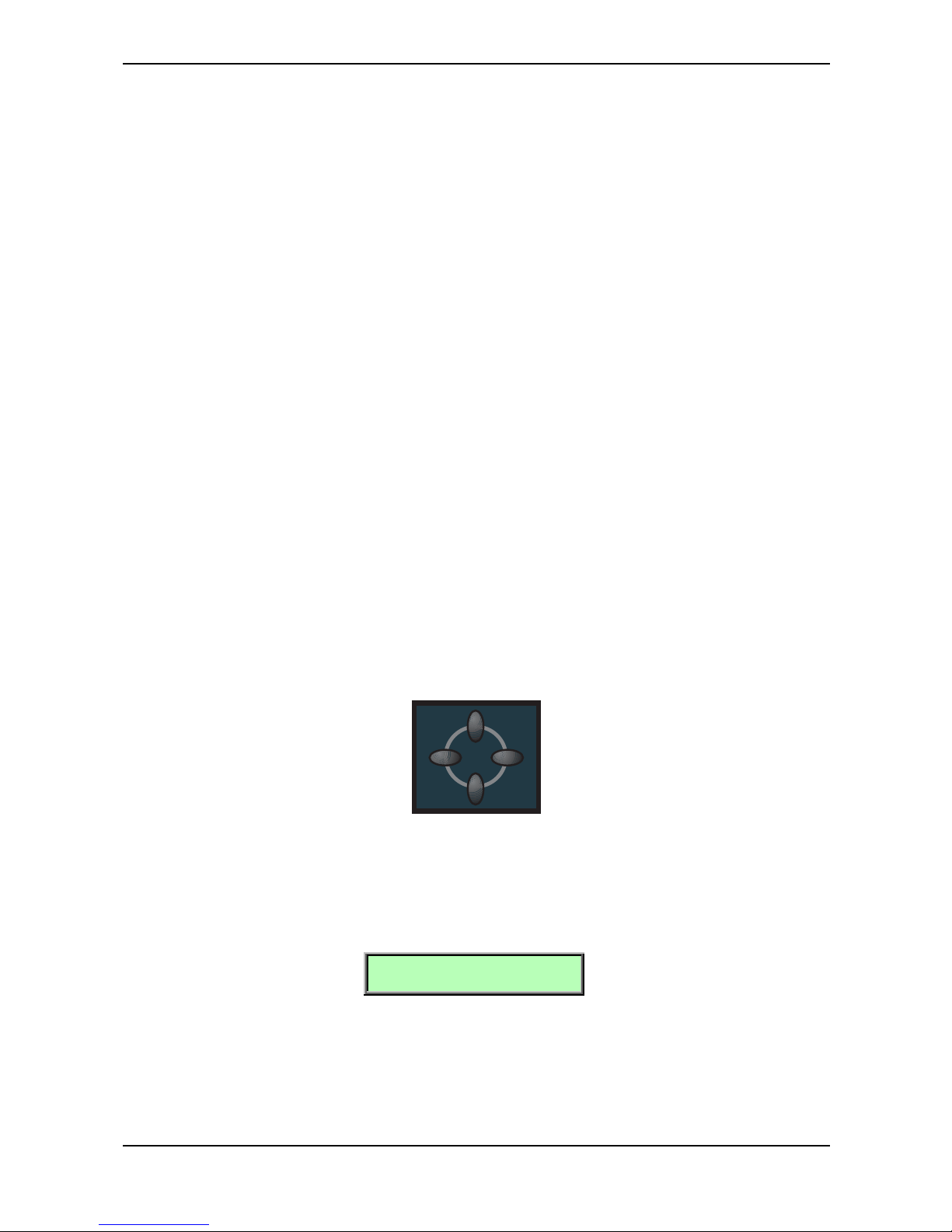
The basic programming of the Waldorf microQ is done via the so-called parameter matrix which
has its most important parameters silksreeened on the machine´s front panel. Changing the
parameters is done with the four endless rotaries on the bottom of the matrix. Changing the edit
level is done with the four navigation buttons left to the parameter matrix. This sounds more
complex than it is. With a simple example you will understand the structure of the microQ handling
easily:
Would you like to change the Resonance of Filter 2? Please proceed as follows:
☞ To access a specific panel parameter:
1. Locate the section that contains the desired parameter on the front panel. For example, if
you want to change Resonance of Filter 2, refer to the Filter section. To do this please
press the upper or lower navigation button until the LED lights up in the Filter section.
2. With the left or right navigation button you can choose Filter 2. The LED will show the
currently selected Filter.
3. With the second endless rotary you can now change the Resonance value of Filter 2.
Whenever you change a parameter by moving a knob or pressing a button, the display shows the
edited parameter and its current value in the upper right corner for a few seconds:
[F2 Resonance 016]
Nimm Oel! T
If you wish to edit a shift-parameter (printed in grey next to the main parameter) you need to keep the
Shift button pressed or push it briefly. If pressed briefly the LED next to the shift button will keep
lighting up until you press it again to edit the main parameters again.
Now you should be able to choose the 7 edit levels with the navigation buttons:
Oscillator, Mixer/Routing, Filter, Amp/FX/Arp., Envelopes, LFOs and Mod Matrix
Page 33
Basic Operation – Editing Parameters
Waldorf microQ User´s Manual 34
For each parameter level you can also access an edit menu, since only the most important parameters
can be directly accessed through the parameter matrix. To activate the edit menu of the selected
section simply press the Edit button in the master section to edit all additional parameters in the
microQ’s display.
Editing Display Menu Parameter
There are display menus for all sections of the parameter matrix The display menus contain additional
parameters that are not directly accessible from the front panel. You can reach these menus by
pressing the Edit button in the master section.
☞ To access a specific display menu parameter:
1. With the navigation buttons you choose the parameter section you wish to reach. For
instance, if you wish to edit the Keytrack of any Oscillator please choose the Oscillator
section in the Parameter matrix.
2. Press the Edit button of the Master section.
3. The first page of the oscillators’ display menu will appear. If you did some editing in this
menu before, the display may show another page. This happens because the microQ
remembers the state of each display menu:
O1 Keytrk|O1 BendRg
+100% | +02
4. Use the page dial to scroll through the menu. Turning the dial clockwise selects the next
page, turning it counterclockwise selects the previous page. You can also press the Edit
button again to select the next page.
5. Use the value dials below the display to adjust the corresponding parameters. Some
display menus consist of only a single parameter. Only the leftmost value dial will be
active then.
6. After finishing all edits, press the Play button in the Master section to return to normal
mode.
While editing display menu parameters, you can also adjust panel parameters and vice versa.
In addition to the Edit button, three other buttons located on the right hand of the Master section
allow you to set up further parameters:
• The Global parameters provide the basic settings of the microQ, valid for all programs.
• The Multi parameters refer to a Multi program. They determine the common setting for all
instruments in the Multi program. Obviously, you can access these parameters only when
the microQ is in Multi mode.
• The Sound parameters refer to a Sound program. If you are in Single Mode, you will edit
the currently played program. If you are in Multi mode, the Sound program for the
currently selected Instrument will be edited. Here you can program the parameter of a
Drum Map, too.
The procedure for setting up these parameters is the same as for adjusting the other display menu
parameters described above.
When you have finished all your edits, you should store the program. Please read the chapter on page
37 about storing programs for further information.
Page 34
Basic Operation – Editing Parameters
35 Waldorf microQ User´s Manual
Edit Buffers
Whenever you edit a program on the microQ, the program is internally copied to an edit buffer.
When you use the Store function to save the edits, the program is copied back from the edit buffer to
the internal memory. The display shows an e behind the program number for every program that is
actually in an edit buffer:
Inst:1 Sound:A001e
Zeitlos T
The microQ has a number of different edit buffers, each holding a program of the specific type when
you edit them:
• 1 Multi edit buffer:
This buffer holds the currently selected Multi in Multi mode.
• 1 Drum Map edit buffer:
This buffer holds the currently edited Drum Map in single or multi mode.
• 16 Sound edit buffers:
Each buffer holds an edited Sound.
The edit buffers aren’t cleared when you select a different program so you can always go back
to the edited program to examine it or do further edits. The only way to “lose” an edit buffer
automatically is when all buffers of this type are already in use and you start to edit another
program. Then the oldest edit buffer is cleared and used to hold the new edit.
Note that all edit buffers are cleared when the microQ is switched off. Use the Store function
as soon as possible after finishing your edits.
Viewing Parameter Values without Change – Peek
The microQ offers a special mode to check parameter values without performing any changes.
☞ To check parameter values without changing them:
1. Press the Peek button, located in the Master section. The LED beside this button will light
up.
2. If you move the control element of any panel parameter, its current value will be shown in
the display. E.g. if you move the Detune knob in the Oscillators section, the display will
show (value may be different):
[01 Detune +09]
3. After a few seconds, the display will return to its previous state. You can also check the
various display menu parameters. Press the Edit button and scroll through the display
menu via the Page Dial or by pressing the Edit button repeatedly. This procedure is also
applicable to the display menu parameters of the Global, Multi or Sound menus.
4. Press the Peek button again. The LED beside the button will go off, indicating that peek
mode has been terminated.
If you don’t check any parameters for a certain time, the Peek mode will be terminated
automatically.
Page 35
Basic Operation – Editing Parameters
Waldorf microQ User´s Manual 36
Comparing Edited Programs with Stored Programs
The Compare function allows you to compare the currently edited program to its original stored
version in the internal memory.
☞ To use the Compare function:
1. Choose the program type to compare as follows:
• If you want to compare a Sound, select the Play page or any of the Edit menus.
• If you want to compare a Multi, select the Multi page.
• If you want to compare a Drum Map, select the Drum Map Edit menu.
2. Press Shift + Compare.
3. The display now shows a c after the program number:
Inst:1 Sound:A001c
Zeitlos T
4. You will hear the unedited version of your program when you play the microQ.
5. Press the Shift + Compare again.
6. The c in the display changes to e again. The edited version of the program is now active
again.
You can only view the original settings. If you select a new program while the Compare
function is active, the Compare status is automatically terminated. No parameters can be edited
with the Compare function active. Any attempt will give you an error message in the display:
[Compare active]
Recalling Edited Programs
You can void edits at any time and return to the original program.
☞ To recall an edited program:
1. Choose the program type to recall as follows:
• If you want to recall a Sound, select the Play page or any of the Edit menus.
• If you want to recall a Multi, select the Multi page.
• If you want to recall a Drum Map, select the Drum Map Edit menu.
2. Press Shift + Recall.
3. The e or c in the display after the program number will disappear. All edits will be recalled
and the program returns back to its stored state.
Page 36
Basic Operation – Editing Parameters
37 Waldorf microQ User´s Manual
Storing Programs
After you have finished editing a program, you must store it if you intend to use it again. Any of the
microQ´s memory locations are available for this purpose. The type of program that is stored depends
on the page you were in before performing the Store function.
☞ To store a program:
1. Choose the program type to store as follows:
• If you want to store a Sound, select the Play page or any of the Edit menus.
• If you want to store a Multi, select the Multi page.
• If you want to store a Drum Map, select the Drum Map Edit menu.
2. Press Shift + Store to activate the Store page.
3. The display shows the Store page where you can select the destination and the program
name:
Store Sound to A051
01[Nimm Oel! T]
4. Use the page dial to select the destination program. The default value is the currently
selected program but you may want to store your edits in a different location. In this case
the name of the chosen Sound Program is temporarily shown and you can choose to
overwrite the old sound or not.
5. Optionally, edit the program name. First select the character to be modified via the first
value dial. Then change its setting via the second value dial. The program name can use up
to 16 characters.
6. When the cursor is on the 16th character and you scroll it even further to the right, you will
come to a second page where you can change the category of the sound. It is strongly
recommended to select an appropriate category for your sound or to create a new
category. This helps you finding your sound later. You can get infos on how to search for a
Sound category in the chapter “Category Search” on page 30. This is how the display
looks:
Store Sound to A001
01[Pad ] <-category
7. Press Shift + Store to store the Program to the selected location.
Whenever you store a program, the selected memory location is overwritten. Therefore, any
previously stored program at this location will be erased and there is no way to get it back.
So, you should do backups of the sounds, multis and Drum Maps regularly. If you want to
restore the factory presets, you can download them as a Standard MIDI File from our website
http://www.waldorf-music.com.
You now have stored the program. When you activate the Store function, the Edit or Compare status
of the stored program is terminated.
By pressing any button before performing the last step, you can discard the Store process at any time.
Use the Store function also if you want to copy programs. There is no need to edit a program
before storing it.
Page 37
Multi Mode – Selecting an Instrument for editing
Waldorf microQ User´s Manual 38
Multi Mode
The Waldorf microQ offers a 16 part Multi mode. As soon as you want to arrange keyboard layers for
a live performance or want to do multi track recordings in a studio, you should start to program your
own Multis that you can use to quickly switch between completely different setups.
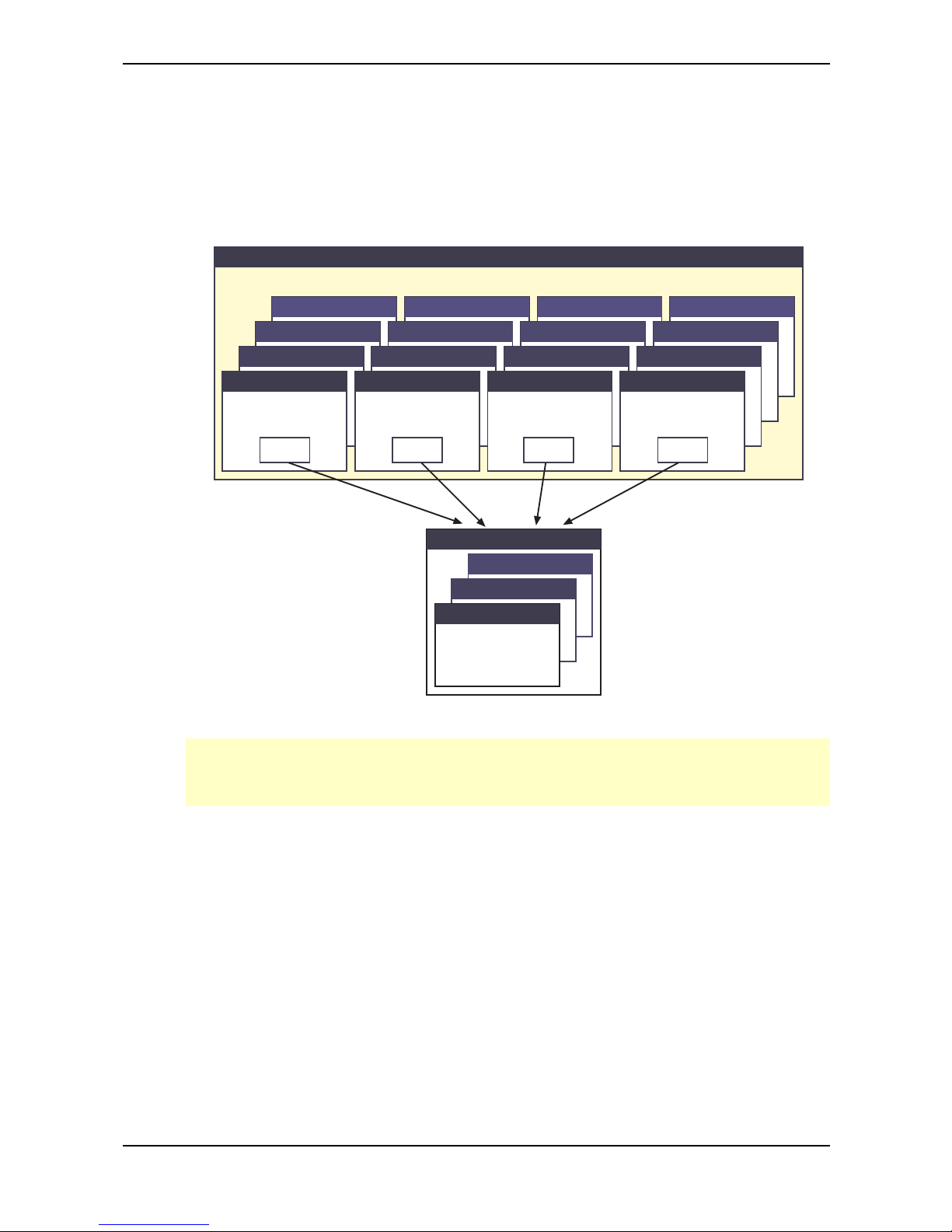
Only a Multi combines the various sections of the microQ like Sounds, MIDI In/Out Channel settings,
or audio output routings. The following picture shows the structure of a Multi.
Instrument 1
Instrument 2
Sound
001
100
.
.
Bank C
Multi Programm
Bank B
Bank A
Instrument 4
Sound
Multi Programm Parameter
Instrument 3
Instrument
Param et er
Instrument 5
Instrument 6
Instrument 8
Instrument 7
Instrument
Param et er
Instrument 9
Instrument 10
Instrument 12
Instrument 11
Instrument
Param et er
Instrument 13
Instrument 14
Instrument 16
Instrument 15
Instrument
Param et er
Sound Sound Sound
Picture 5: Multi Program architecture
Setting up a Multi requires some organizational work, as it does on all synthesizers, but you
should do it anyway because it eases your work with the microQ when you use it live or for
recording.
Selecting an Instrument for editing
Before you can adjust the Instrument Parameters of a particular Instrument, you have to select it. The
Multi mode of the microQ offers 16 Instruments that can be played at a time via MIDI. The 16
Instruments are organized into 4 banks with each 4 Instruments.
☞ To select an Instrument:
1. Press Shift+Inst. 1…4 to select one of the four Instrument banks.
2. Press Inst. 1…4 to select one of the Instruments of the selected bank.
or
1. Hold down the Multimode button.
2. Choose the desired instrument with the red dial.
Page 38
Multi Mode – Instrument settings
39 Waldorf microQ User´s Manual
When the Play page is selected, the display shows the Instrument number in the top left corner as
follows:
Inst:4 Multi:001
Sequencer Multi
The instruments are numbered consecutively from 1 to 16. In the display shown above, Instrument 4
is selected. If you want to select Instrument 12, for instance, you have to access Bank 3 by pressing
Shift + Inst.3 and then button Inst.4 to switch to Instrument 12.
When one of the Instrument parameter pages is selected, the current Instrument number is shown in
the top right corner as follows:
Channel |Output 4
global |Main Out
Don’t confuse Instruments with MIDI Channels. Although you can set up a Multi that uses
separate MIDI Channels in ascending order for all Instruments, it can also be that a couple or
all Instruments are set to the same MIDI Channel. Please read the description below to see how
the MIDI Channel for a particular Instrument is set.
☞ To call the Multi parameter pages:
1. Make sure that the Multimode LED is lit to indicate that the Multi mode is active.
2. Press the Multi button in the Master section. The display changes to the Multi or
Instrument parameter page that was active when you last left the Multi parameter pages
the last time.
3. You can change the pages with the red page dial or by pressing the Multi button several
times.
Instrument settings
The instrument parameters specify the individual settings of each instrument in a Multi Program. You
can edit the audio output, transpose function or tuning, key range and velocity range for a selected
sound.
Sound Bank and Number A…D 001…100
Each Instrument points to one Sound in memory. The display shows the Sound name in the upper row
and the Sound bank and number in the lower row as follows:
[Nimm Oel! T ]1
Bank: A sound: A001
☞ To select a Sound for an Instrument:
• Use the left display dial to select Bank A…D from which the Sound program is taken.
• Use the right display dial to select the Instrument’s Sound program 001…100.
In a Multi-Program you can use only one Drum Map at a time. When you’re assigning a Drum
Map to an instrument, any other instrument using a Drum Map will be restored to the normal
program assignment.
Page 39
Multi Mode – Instrument settings
Waldorf microQ User´s Manual 40
Volume !Panning 1
100 ! center
Volume 000…127
Volume sets the output volume of the selected Instrument.
This Volume parameter sets the maximum output volume of the selected Instrument. If you use
MIDI Controller #7 (Channel Volume) to change the volume of the Instruments that receive on
this MIDI channel, the real output level is scaled to the volume set up in this parameter. This
means that if you set Instrument Volume to 10 and Controller #7 to 127, the maximum output
volume is 10.
Panning left 64...center...right 63
Determines the panning position of the selected instrument. The setting left 64 stands for full left, right
63 for full right. In case you want to have the sound in the mid position select center.
With this function you can set the stereo outputs of the microQ to mono outputs by selecting the full
left or full right position for the panning.
If stereo effects are active, e.g. delay, the effect will still sound in both outputs even if the basic
sound is set to full left or full right.
Channel !Output 1
01 !Main Out
Channel global, omni, 1…16
Channel sets the MIDI Channel for the selected Instrument. This MIDI channel is used to send MIDI
messages and to receive MIDI messages for this Instrument when Status is set to Midi.
• global means that the selected Instrument receives and sends on the MIDI channel set up
in the Global menu. This setting is recommended for a Multi that is intended for use in a
live performance.
• omni means that the selected Instrument receives all MIDI channels and sends on the MIDI
channel set up in the Global menu. This setting is not recommended. Only use it for
diagnostic purposes when you need to know if the microQ receives any MIDI messages at
all.
• 1…16 means that the selected Instrument receives and sends on this MIDI channel. This
setting is recommended for a Multi that is intended for multi track playback with a
software sequencer.
Output Main Out, Sub Out 1, Sub Out 2, FX1, FX2, FX3, FX4, Aux
Output sets the audio output of the selected Instrument. The Instruments 1…4 can only be routed to
the physical outputs, the Instruments 5…16 can also be routed to the effect busses of the Instruments
1…4.
This routing is not possible for a Drum Map.
• Main Out means that the selected Instrument plays over the Main Out jacks.
• Sub Out1 means that the selected Instrument plays over the Sub Out 1 jacks.
Page 40
Multi Mode – Instrument settings
41 Waldorf microQ User´s Manual
• Sub Out2 means that the selected Instrument plays over the Sub Out 2 jacks.
• FX1…FX4 (only available on Instruments 5…16) means that the selected Instrument is
routed to the respective effect bus of Instrument 1…4 and therefore also plays back over
the same physical output.
• aux means that the selected instrument is routed to the internal audio bus. So you can use
this Instrument to feed the 5 FX or the vocoder. For more information refer to the chapter
"Effects" on page 89 and page 93.
The Instruments 1…4 define the effects that are used in the selected Multi. All other Instruments
are played back without effects unless you route them to one of the effect busses FX1…FX4. If
you do so, these particular Instruments automatically use the same physical outputs that are set
up in the respective Instrument 1…4.
If you have choosen aux for an instrument you don´t hear its audio signal on the physical
outputs.
Status Off, Midi
Status 1
Midi
Status sets the send and receive status of the selected Instrument. This means whether the Instrument
can be played by MIDI or is disabled.
• Off means that the selected Instrument is disabled.
• Midi means that the selected Instrument can be played by MIDI.
FX1 Mix ! FX2 Mix
064 ! 000
FX1/2 Mix 000…127
FX1 and FX2 Mix control the volume ratio between the original signal and the effect output of the
selected instrument. If set to 0, the dry signal is sent to the outputs only so that no effects can be
heard. Higher values will increase the effect signal. At maximum setting, the pure effect signal will be
heard.
FX1 Mix is only available for Instrument 1...4. FX2 Mix is available for all 16 instruments. In
the Global menu FX2 can be assigned either globally or to Instruments 1 through 4. Please also
see the chapter “Global Menu” on page 130.
Transpose|Detune 1
+00 | +00
Transpose -48…+48
Transposes the Instrument in semitone steps. I.e., a value of –12 means that the Instrument sounds
one octave lower than it was originally programmed.
Page 41
Multi Mode – Instrument settings
Waldorf microQ User´s Manual 42
Detune -64…+63
Detunes the Instrument in steps of 1/64th of a semitone.
You can set up nice layered sounds with Transpose and Detune. Activate two Instruments
and set their parameters to identical values including the sound number. Then simply transpose
one Instrument by one octave, and you have a fat layer sound. Or set them both to the same
octave and set Detune of one Instrument to –05 and the other to +05.
LowVelo |HiVelo 1
001 | 127
LowVelo 001…127
LowVelo allows you to limit the velocity range in which the instrument is played. Only notes with a
velocity higher or equal to the selected value are passed through. Set this parameter to 1, if you want
to turn velocity switching off.
HiVelo 001…127
HiVelo is the counterpart to LowVelo. Only notes with a velocity lower or equal to the selected
value are passed through. Set this parameter to 127, if you want to turn velocity switching off.
LowKey |HighKey 1
C-2 | G8
LowKey C-2…G8
Analogous to the velocity switching parameters, the key range can be restricted for the instrument’s
tone generation. Only notes with a key number higher or equal to the selected value are passed
through. Set this parameter to C-2 if you want to use the full keyboard range.
HighKey C-2…G8
HighKey is the counterpart to the LowKey parameter. Only notes with a key number lower or equal
to the selected value are passed through. Set this parameter to G8 if you want to use the full keyboard
range.
Ctrl W…Ctrl Z 0…120
Ctrl W |Ctrl X 1
002 (02) |004 (04)
Ctrl Y |Ctrl Z 1
011 (0B) !012 (0C)
These parameters are used to define arbitrary MIDI Continuous Controllers as modulation sources for
the Sounds in the active Multi. You can set up four Controls, W, X, Y and Z, for this purpose. Each
value represents a MIDI Continuous Controller number that is used when you assign its parameter as
modulation source in the Modifiers or the Modulation Matrix. The highest possible Controller number
is 120 because all higher numbers are reserved for non-real-time purposes. If global is selected, the
corresponding settings for Ctrl W...Z made in the global parameter section are used.
Page 42
Multi Mode – Instrument settings
43 Waldorf microQ User´s Manual
The most important Sound parameters of the microQ can be controlled by MIDI Continuous
Controller messages. If you set one of the Ctrl W…Ctrl Z to a Controller that is also used for a
Sound parameter, the microQ disables this Controller as Sound parameter Controller and uses
it exclusively for one of the Ctrl W…Ctrl Z.
This is an important issue when you send Sound parameter changes by tweaking parameters on
the front panel. The Sound parameter is sent out as Controller but can’t be received as long as
any of the Ctrl W…Ctrl Z remains assigned the same Controller number.
Multi Volume 0…127
Multi Volume 1
127
Multi Volume sets the overall volume for the selected Multi program. It affects all Instruments of the
Multi program, so if you would set Multi Volume to 0, you won´t hear anything.
Multi Volume is used to set several Multi programs to similar output levels, especially in live
situations. While recording in a studio, you should set Multi Volume to 127 to get the highest
possible Signal-to-Noise ratio.
Multi Tempo 40…300
[Multi Tempo 120]
Multi Tempo sets the global tempo for all instruments in the selected Multi program. It affects all
arpeggiators and all LFO that are set to clocked. Please read the chapter “The Tempo” on page 124
for further information.
The Multi Tempo parameter is controlled by the Tempo dial in the Amp/FX/Arp. section, so it
doesn’t need to have an entry in the Multi parameter pages.
Page 43
Multi Mode – Instrument settings
Waldorf microQ User´s Manual 44
Multi Mixer (not available for the microQ lite)
VOL
ˇ_____ˇ____ˇ____ 127
The Multi Mixer offers fast graphical editing of Volume, Panning and Effect Send for all 16
instruments. The 16 horizontal segments represent the 16 available instruments. A small cursor below
the corresponding segment indicates the chosen instrument. With the red dial you can switch
between Level Mode and VU Mode.
Level Mode
In Level Mode the settings for all 16 instruments can be quickly edited. The left display knob selects
the desired parameter. The right display knob changes the value. You can easily compare values for
all 16 instruments at the same time. The following parameters are available:
• Vol shows the actual volume of the instruments in Multimode. Here the volume can be
changed infinitely variable from 0 to 127
• FX1 shows the FX1 Mix Level of the Multi Instruments. It can be changed infinitely variable
from 0 to 127.
• FX2 shows the FX2 Mix Level of the Multi Instruments. It can be changed infinitely variable
from 0 to 127.
VU Mode
The VU Mode graphically shows all incoming Midi signals and current signal volume as a bargraph
(like on a signal analyzer.) This allows you to check which instruments are receiving Midi messages.
All of the Multimode parameters can be changed while in VU Mode. In addition to the Level Mode
parameters, the following parameter is also available:
• PAN sets the panorama position infinitely variable from 0 to 127
The Multi Mixer offers the possibility to mute or unmute instruments during a live performance.
Page 44
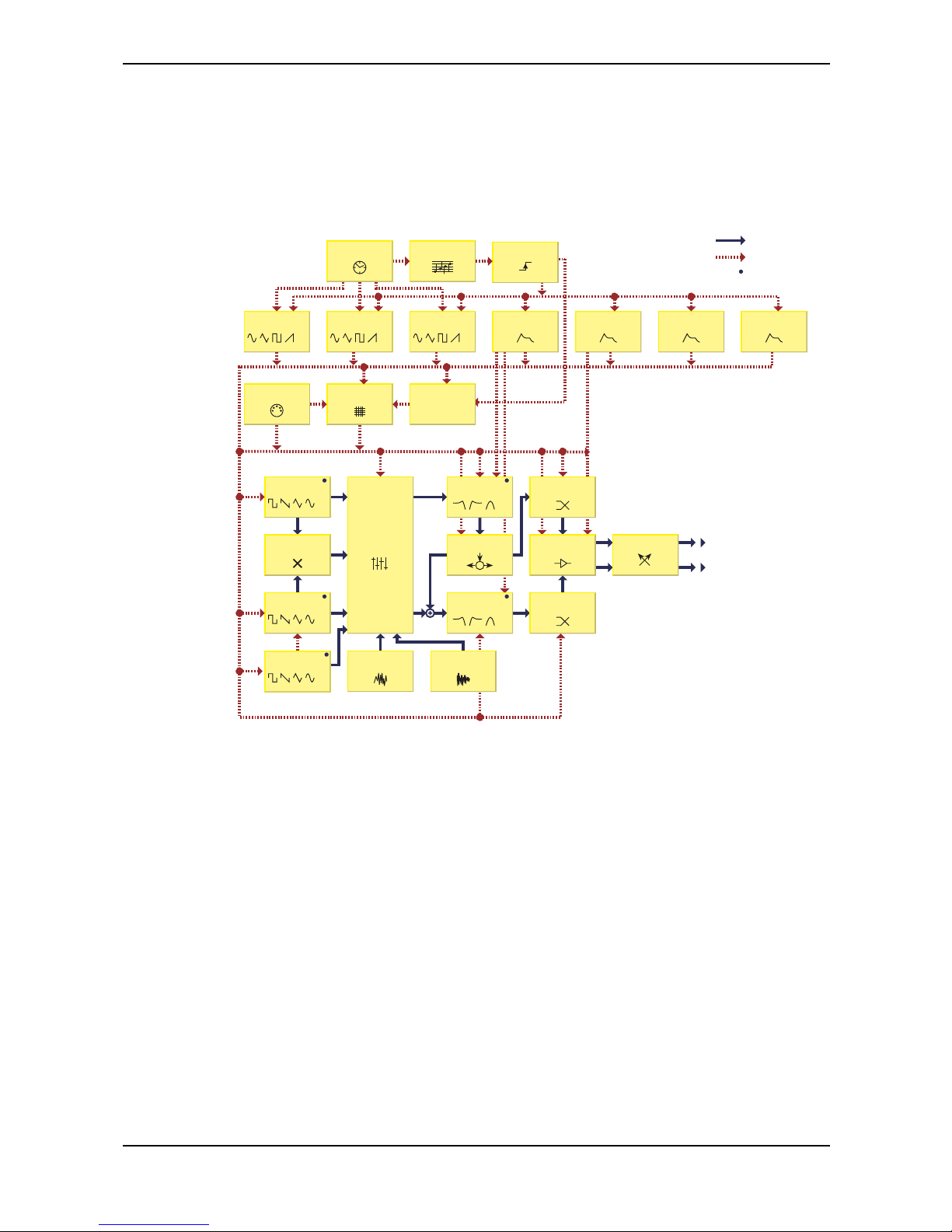
Sound Parameters – Overview of Functions
45 Waldorf microQ User´s Manual
Sound Parameters
Overview of Functions
The Waldorf microQ consists of numerous sound-shaping components. The following overview gives
you an idea of how the individual components interact:
Output
R
L
Audio Signal
Controller Signal
Sync
FM Destination
Oscillator 1
…
Oscillator 3
…
External Audio
Signal
Noise Generator
Filter 1
…
Filter 2
…
Routing
Oscillator 2
…
Pan 2
Ring Modulator
Pan 1
Amplifier
FX1 / FX 2
Modifiers
f(x, y)
Modulation
Matrix
Filter Envelope
Amplifier
Envelope
Envelope 3 Envelope 4LFO 3
…
LFO 2
…
LFO 1
…
Arpeggiator
Trigger
MIDI Clock
MIDI Input
Mixer
Picture 6: Block schematic diagram of a sound
As you can see, the microQ consists of two different types of components for sound generation and
sound shaping:
• Oscillators, Ring Modulator, Noise Generator, External Audio Signal, Mixer, Filters,
Amplifier, Effects:
These modules represent the audio signal flow. Sound generation actually occurs within
the Oscillators. They produce square, sawtooth, triangular, sine and alternative waveforms.
The Mixer follows the Oscillators in the signal chain, which is where the Oscillators’
output signals are mixed. Noise or signals received through the audio inputs can also be
added to the mix. The Filter then shapes the sound by amplifying (boosting) or attenuating
(dampening) certain frequencies. The Amplifier and the Effects are located at the end of the
signal chain. They determine the overall volume of the signal and add some effects like
chorus, flanger, delay etc.
• LFOs, Envelopes, Modifiers, Modulation Matrix:
These modules are called Modulators. The Modulators are designed to manipulate or
modulate the sound generating components to add dynamics to sounds. The Lowfrequency Oscillators (LFO) are designed for periodic or recurring modulations while
Envelopes are for modulations that occur once on each note. These generators are
Page 45
Sound Parameters – Modulation Speed Levels
Waldorf microQ User´s Manual 46
assigned to parameters through the Modulation Matrix and influence these parameters to
alter a sound. In addition, the Modifier unit can process various mathematical operations
and functions on the modulation signals.
Modulation Speed Levels
The microQ offers three levels of modulation speeds: FM, Fast Modulation and Standard Modulation.
This separation assures maximum flexibility in sound generation while keeping the amount of
processor power needed to calculate a voice as low as possible. You will find separate descriptions of
how to access the different modulation types in the chapters below. The three modulation speed
levels are categorized as follows:
FM (Frequency Modulation)
This is the fastest modulation speed level. These calculations are performed for each generated
sample or, in other words, 48000 times per second (48kHz). Five modules of the microQ’s sound
generation offer FM - the three oscillators and the two filters. When you browse the list of available
sources for this type of modulation, you will find almost exclusively those sources that make sense to
modulating the destination with sample speed. This includes the oscillators, noise, the LFO, the
envelopes and so on. You won’t find sources like modwheel or velocity, because their values change
incredibly slowly, compared to an oscillator playing at a pitch of i.e. 10kHz. The following table
shows all available FM Sources:
FM Sources Description
Off No modulation
Osc1 Oscillator 1 Signal
Osc2 Oscillator 2 Signal
Osc3 Oscillator 3 Signal
Noise Noise Generator Signal
LFO1 LFO 1 Signal
LFO2 LFO 2 Signal
LFO3 LFO 3 Signal
FilterEnv Filter Envelope Signal
AmpEnv Amplifier Envelope Signal
Env3 Envelope 3 Signal
Env4 Envelope 4 Signal
Table 3: FM Sources
FM needs a lot of CPU Power which leads to less polyphony.
Fast Modulation
Though not calculated in sample speed, the Fast Modulation calculations are performed in audio
speed: more than 5000 times per second (>5kHz). Most of the modulations in the microQ are
performed at this speed level. The following table lists all pre-routed Fast Modulation destinations:
Page 46
Sound Parameters – Modulation Speed Levels
47 Waldorf microQ User´s Manual
Pre-routed Modulation destinations Description
Oscillator PitchMod Global pitch modulation of all three Oscillators at once
Oscillator 1 PWM Pulse width modulation of Oscillator 1
Oscillator 2 PWM Pulse width modulation of Oscillator 2
Oscillator 3 PWM Pulse width modulation of Oscillator 3
Filter 1 CutoffMod Cutoff modulation of Filter 1
Filter 1 Env Envelope amount of Filter 1 cutoff
Filter 1 Velo Envelope velocity amount of Filter 1 cutoff
Filter 1 PanMod Panning modulation of Filter 1 output
Filter 2 CutoffMod Cutoff modulation of Filter 2
Filter 2 Env Envelope amount of Filter 2 cutoff
Filter 2 Velo Envelope velocity amount of Filter 2 cutoff
Filter 2 PanMod Panning modulation of Filter 2 output
Amplifier AmpMod Amplitude modulation
Amplifier Volume Output shaped by the Amplifier Envelope
Table 4: Pre-routed Modulation destinations
In addition to the pre-routed Fast Modulation destinations, the microQ offers eight slots for individual
routing connections that are updated at the same speed level: the Fast Modulation Matrix. The
following table lists all available destinations for a Fast Modulation Matrix slot:
Fast Modulation Matrix destinations Description
Pitch Global pitch of all three Oscillators at once
O1 Pitch, O2 Pitch, O3 Pitch Pitch of Oscillator 1…3
O1 PW, O2 PW, O3 PW Pulse width of Oscillator 1…3
O1 FM, O2 FM, O3 FM FM Amount modulation of Oscillator 1…3
O1 Level, O2 Level, O3 Level Mixer level of Oscillator 1…3
O1 Bal., O2 Bal., O3Bal. Filter 1/2 Balance of Oscillator 1…3
RingLevel Mixer ring modulation level
Ring Bal. Filter 1/2 Balance of Oscillator 1
N/E Level Mixer level of Noise or External signal
N/E Bal. Filter 1/2 Balance of Noise or External signal
F1 Cutoff, F2 Cutoff Cutoff of Filter 1…2
F1 Reson., F2 Reson. Resonance of Filter 1…2
F1 FM, F2 FM FM Amount modulation of Filter 1…2
F1 Drive, F2 Drive Drive of Filter 1…2
F1 Pan, F2 Pan Pan of Filter 1…2
Volume Amplifier output volume
Table 5: Fast Modulation Matrix destinations
Page 47
Sound Parameters – Modulation Speed Levels
Waldorf microQ User´s Manual 48
The following table shows all available Fast Modulation sources:
Fast Modulation sources Description
Off No modulation
LFO1 LFO 1 Signal
LFO1*MW LFO 1 Signal shaped by the Modwheel
LFO2 LFO 2 Signal
LFO2*Prs LFO 2 Signal shaped by Aftertouch
LFO3 LFO 3 Signal
FilterEnv Filter Envelope Signal
AmpEnv Amplifier Envelope Signal
Env3 Envelope 3 Signal
Env4 Envelope 4 Signal
Velocity MIDI Velocity
Modwheel MIDI modulation wheel (controller #1)
Pitchbend MIDI pitchbend signal
Pressure MIDI channel pressure
Table 6: Fast Modulation sources
Standard Modulation
The Standard Modulations are calculated at normal speed, which is still fast enough for the most
modulation purposes, e.g. when dealing with the modulation wheel or velocity. The Standard
Modulation slots offer an extended set of modulation sources and destinations compared to the Fast
Modulation slots. The Standard Modulation speed level is only available in the Modulation Matrix,
while all other modulations are performed as Fast Modulations or FM.
Standard Modulation Matrix
destinations
Description
Pitch Global pitch of all three Oscillators at once
O1 Pitch, O2 Pitch, O3 Pitch Pitch of Oscillator 1…3
O1 PW, O2 PW, O3 PW Pulse width of Oscillator 1…3
O1 FM, O2 FM, O3 FM FM Amount modulation of Oscillator 1…3
O1 Level, O2 Level, O3 Level Mixer level of Oscillator 1…3
O1 Bal., O2 Bal., O3Bal. Filter 1/2 Balance of Oscillator 1…3
RingLevel Mixer ring modulation level
Ring Bal. Filter 1/2 Balance of Oscillator 1
N/E Level Mixer level of Noise or External signal
N/E Bal. Filter 1/2 Balance of Noise or External signal
F1 Cutoff, F2 Cutoff Cutoff of Filter 1…2
F1 Reson., F2 Reson. Resonance of Filter 1…2
F1 FM, F2 FM FM Amount modulation of Filter 1…2
F1 Drive, F2 Drive Drive of Filter 1…2
F1 Pan, F2 Pan Pan of Filter 1…2
Volume Amplifier output volume
LFO1Speed, LFO2Speed, LFO3Speed Speed of LFO 1…3
Page 48
Sound Parameters – Modulation Speed Levels
49 Waldorf microQ User´s Manual
FE Attack Attack rate of Filter Envelope
FE Decay Decay (and Decay 2) rate of Filter Envelope
FE Sustain Sustain (and Sustain 2) level of Filter Envelope
FE Release Release rate of Filter Envelope
AE Attack Attack rate of Amp Envelope
AE Decay Decay (and Decay 2) rate of Amp Envelope
AE Sustain Sustain (and Sustain 2) level of Amp Envelope
AE Release Release rate of Amp Envelope
E3 Attack Attack rate of Envelope 3
E3 Decay Decay (and Decay 2) rate of Envelope 3
E3 Sustain Sustain (and Sustain 2) level of Envelope 3
E3 Release Release rate of Envelope 3
E4 Attack Attack rate of Envelope 4
E4 Decay Decay (and Decay 2) rate of Envelope 4
E4 Sustain Sustain (and Sustain 2) level of Envelope 4
E4 Release Release rate of Envelope 4
M1F Amount Modulation amount of M1F
M2F Amount Modulation amount of M2F
M1S Amount Modulation amount of M1S
M2S Amount Modulation amount of M2S
01SubDiv, 02SubDiv Frequency divide of the sub oscillator1...2
01SubVol, 02SubVol Volume of the sub oscillators 1...2
Table 7: Standard Modulation Matrix destinations
The following table shows all available Standard Modulation sources:
Standard Modulation Matrix sources Description
Off No modulation
LFO1 LFO 1 Signal
LFO1*MW LFO 1 Signal shaped by the Modwheel
LFO2 LFO 2 Signal
LFO2*Prs LFO 2 Signal shaped by Aftertouch
LFO3 LFO 3 Signal
FilterEnv Filter Envelope Signal
AmpEnv Amplifier Envelope Signal
Env3 Envelope 3 Signal
Env4 Envelope 4 Signal
Keytrack MIDI note number
Velocity MIDI Velocity
Rel. Velo MIDI note release velocity
Pressure MIDI channel pressure
Poly Prs. MIDI polyphonic pressure
Pitchbend MIDI pitchbend signal
Modwheel MIDI modulation wheel (controller #1)
Sust. Ctr MIDI sustain pedal (controller #64)
Foot Ctr MIDI foot control (controller #4)
BreathCtr MIDI breath control (controller #2)
Control W, X, Y, Z assignable MIDI controller W, X, Y, Z
Page 49
Sound Parameters – Triggering of Voices
Waldorf microQ User´s Manual 50
Ctr Delay Modifier Delay
Modif. #1...#4 Modifier result #1...#4
minimum constant for minimum modulation (equals 0)
MAXIMUM constant for maximum modulation (equals +1)
Voice Num current voice number as mod source
Voice %16, %8, %4, %2 used voice number as mod source
Unisono V Number of unisono voices
U. Detune Detuning of all unisono voices
U. De-Pan De-panning of all unisono voices
U. De-Oct De-octaving of all unisono voices
Table 8: Standard Modulation Matrix sources
Triggering of Voices
As soon as a note is played, the microQ triggers one or several voices. How this triggering is done is
set by the following parameters. You can find these parameters in the Sound Edit menu located in the
Master section.
Sound Edit Menu
Mode | Unisono
Poly | Dual
Mode Poly / Mono
Controls if the Sound can be played polyphonically or monophonically.
• Poly means that each note triggers its own voice or voices, as on a piano.
• Mono means that only the last played note sounds. All other notes are stored in an internal
list but aren’t played. As soon as you release the note that is currently played, the second
last note is played and so on. When you play legato, only the first note that was played
triggers the envelopes. All later notes use these envelopes, but sound in the pitch you’ve
played. This mode is for sustained sounds like typical 70’s solo sounds.
When Mono is selected and you have set up a decaying volume envelope for the selected
Sound, you might not hear anything after playing several notes because of the envelopes
decaying to 0.
Unisono Off / Dual / 3…6
Controls how many voices are triggered when a note is played.
• Off means that a note triggers one voice. This is the standard mode.
• Dual means that a note triggers two voices. Both voices have high priority so they can cut
off other voices that are played.
• 3…6 means that this number of voices is triggered when a note is played. Only the first
voice has high priority, meaning that it can cut off other played notes. The other voices can
only sound if any voices are free or if there are other unison voices with lower priority that
could be cut off. This ensures that older notes play at least one voice as long as the voice
allocation isn’t forced to steal even this voice for a new note.
Page 50
Sound Parameters – Triggering of Voices
51 Waldorf microQ User´s Manual
Please note that the chosen number of unisono voices will respectively lower the number of
available voices.
Unisono Detune 000…031
Unisono Detune
012
Controls the detuning of the Unison voices. Each voice is detuned differently; with Unisono Detune,
you control the overall amount.
Unisono Detune is perfectly suited to thickening the tone. Arpeggios benefit too from the
detune function.
Trig FE ! AE (mono)
Normal ! Single
Triggering of the Filter Envelope (Trig FE)
Determines the triggering of the Filter Envelope.
• Normal means that every Note starts the filter envelope of its own voice.
• Single means that the envelopes of all voices of a selected program behave like a single
envelope. This common envelope starts as soon as the first note is played. The sustain level
remains until the last note is released. Afterwards the release phase is active.
Triggering of the Amplifier Envelope (AE (Mono))
Determines the triggering of the Amplifier Envelope.
• Normal means that every Note starts the amplifier envelope of its own voice.
• Single means that the envelopes of all voices of a selected program behave like a single
envelope. This common envelope starts as soon as the first note is played. The sustain level
remains until the last note is released. Afterwards the release phase is active. This setting is
only active as long as the Parameter Mode is set to Mono. Otherwise the envelope
behaves as though set to Normal.
Trig E3 ! E4 (mono)
Normal ! Single
Triggering of the Envelopes 3 (Trig E3) and 4 E4 (mono)
Determines the triggering of the Envelopes 3 and 4.
• Normal means that every Note starts the amplifier envelope of its own voice.
• Single means that the envelopes of all voices of a selected program behave like a single
envelope. This common envelope starts as soon as the first note is played. The sustain level
remains until the last note is released. Afterwards the release phase is active. This setting is
only active as long as the Parameter Mode is set to Mono (only Envelope 4). Otherwise the
envelope behaves as though set to Normal.
Page 51
Sound Parameters – Triggering of Voices
Waldorf microQ User´s Manual 52
Rename Sound
Rename Sound
02[Init Sound V1.0 ]
This function changes the program’s name. Choose the position of the name with the left parameter
knob and change the character of the selected position with the right parameter knob. The numbers to
the left in the lower row show the currently selected postition in the name. You can edit up to 16
characters per name. To save all your changes, please store the sound before leaving this menu.
Page 52
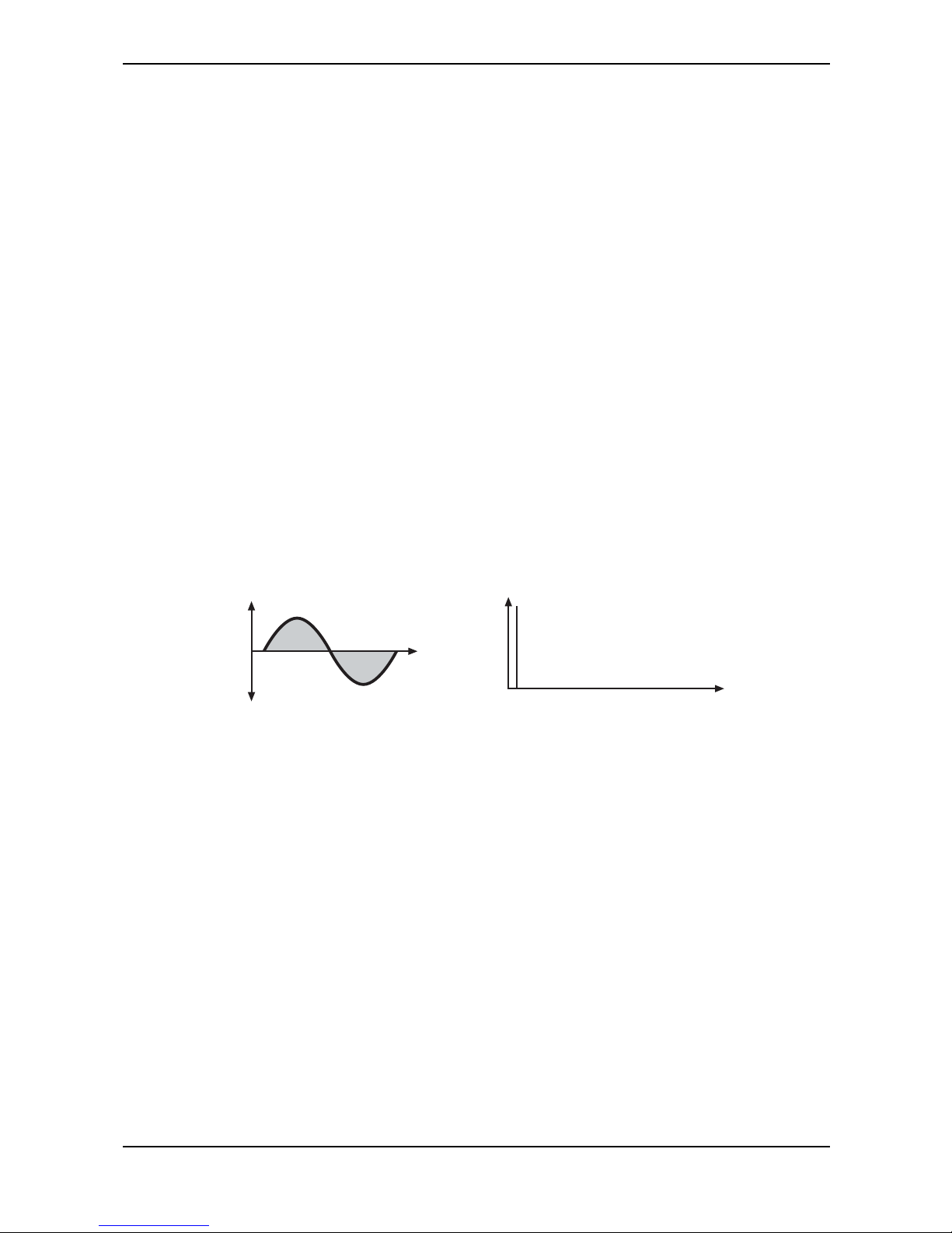
Sound Parameters – Oscillators Introduction
53 Waldorf microQ User´s Manual
Oscillators Introduction
The Waldorf microQ is equipped with three oscillators that have almost identical functionality.
Oscillator Shapes
The oscillator is the first building block of a synthesizer. It delivers the signal that is transformed by all
other components of the synthesizer. In the early days of electronic synthesis, Robert A. Moog found
out that most real acoustic instrument waveforms could be reproduced by using abstracted electronic
versions of these waveforms. He wasn’t the first who came to that conclusion, but he was the first in
recreating them electronically and building them into a machine that could be used commercially.
What he implemented into his synthesizer were the still well-known waveforms sawtooth, square and
triangle. For sure, this is only a minimal selection of the endless variety of waveforms, but the Waldorf
microQ gives you exactly these waveforms at hand, plus other classic waveforms like pulse (which is
the father of the square waveform) and the sine wave (also part of every other waveform).
Now, you probably know how these waveforms look and sound, but the following chapter gives you
a small introduction into the deeper structure of these waveforms. Let’s start with the most basic one.
The Sine Wave
The Sine Wave is the purest tone that can be generated. It consists only of one harmonic, the
fundamental, and has no overtones. The following picture shows the sine wave and its frequency
representation:
14 8 12 16
Frequency
Magnitude
Time
Amplitude
Harmonics
The Sine Wave
There is no acoustic music instrument that generates a pure sine wave; the only instrument that comes
close to it is the pitch fork. Therefore, the sine wave sounds a little artificial to the ear. However, the
sine wave can be an interesting oscillator waveform to emphasize a certain harmonic while other
oscillators are playing more complex waveforms, or as FM source for frequency modulation.
The sine wave is the most basic building block of each waveform. Any waveform can be broken
down to several or many sine waves that are arranged with different frequencies and magnitudes.
These sine waves are called partials. In most waveforms, the partial with the lowest frequency is
dominant, meaning that this partial is used by the ear to determine the pitch of the tone. This partial is
called fundamental. All other partials are called overtones. So, the second partial is the first overtone.
Cyclic waveforms such as the waveforms in the microQ only feature sine waves in integer frequency
ratios to the fundamental like double frequency, triple frequency and so on. Those partials are called
harmonics because their frequency is a harmonic multiple of the fundamental.
Confusing? Let’s generalize it to cyclic waveforms: a cyclic waveform like sawtooth, square etc. only
consists of harmonic partials. The harmonic with the lowest frequency is dominant and therefore
called fundamental. All other harmonics are called overtones.
Page 53
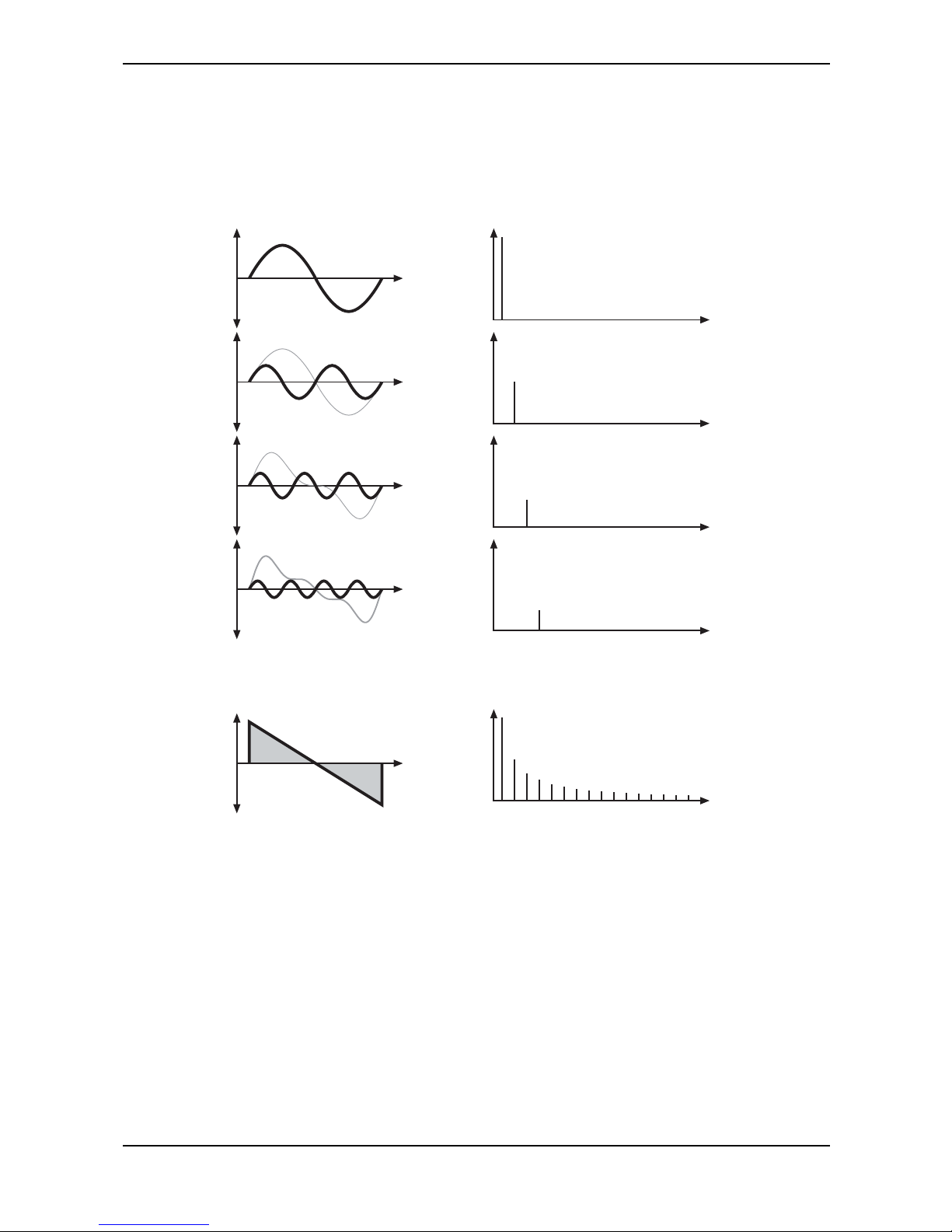
Sound Parameters – Oscillators Introduction
Waldorf microQ User´s Manual 54
The Sawtooth Wave
The Sawtooth Wave is the most popular synthesizer waveform. It consists of all harmonics in which
the magnitude of each harmonic descends by the factor of its position. This means that the first
harmonic (the fundamental) has full magnitude, the second harmonic has half magnitude, the third
harmonic has a third magnitude and so on. The following picture shows how the individual
harmonics build up the sawtooth wave:
14 81216
Frequency
Magnitude
Time
Amplitude
+
=
1st Harmonic
Magnitude 1
2nd Harmonic
Magnitude 1/2
3rd Harmonic
Magnitude 1/3
4th Harmonic
Magnitude 1/4
Harmonics
+
+
+
.
.
Picture 7: Additive components of the Sawtooth wave
The sawtooth wave was thought as an abstraction of the timbre of string and brass instruments. You
can easily understand that when you think of a violin. Imagine a bow pulling the string slightly into
one direction. At one point, the string abruptly comes off the bow and swings back to its original
position. The bow is still moved and so it catches the string again and the procedure is repeated. The
result is a waveform that looks like a sawtooth. The same is true for a brass instrument. The string in
this case are the lips while the bow is the air. The lips are moved by the air to a certain extent and
abruptly move back to their original position.
Page 54
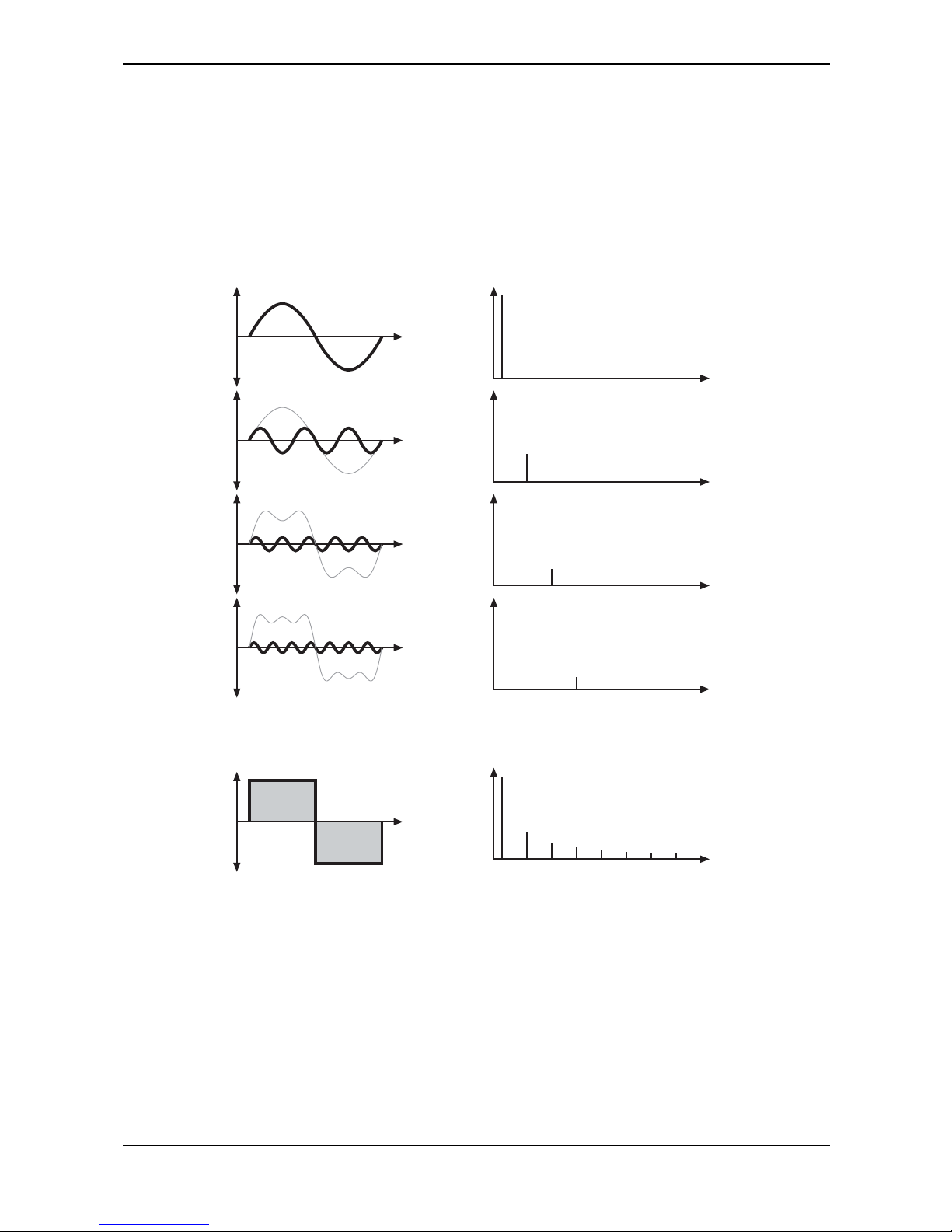
Sound Parameters – Oscillators Introduction
55 Waldorf microQ User´s Manual
The Square Wave
The Square Wave is a special waveform generated by a pulse waveform with 50% pulse width. This
means that the positive part of the waveform has equal length to the negative part. The pulse
waveform can have other pulse widths as you will read later. For now, we´ll talk about the square
wave as a unique waveform. The square wave consists of all odd harmonics in which the magnitude
of each harmonic descends by the factor of its position. This means that the first harmonic has full
magnitude, the third harmonic has a third magnitude, the fifth harmonic has a fifth magnitude and so
on. The following picture shows how the individual harmonics build up the sawtooth wave:
13
579
Frequency
Magnitude
Time
Amplitude
+
=
1st Harmonic
Magnitude 1
5th Harmonic
Magnitude 1/5
7th Harmonic
Magnitude 1/7
Harmonics
+
+
+
.
.
11 13 15
3rd Harmonic
Magnitude 1/3
Picture 8: Additive components of the square wave with 50% pulse width
The square wave was thought as an abstraction of wind instruments like a panflute or a recorder.
They consist of a tube that can contain a certain amount of air. The player blows air through the tube
in a way such that the air starts to vibrate. This vibration is almost completely symmetrical, resulting
in a hollow timbre.
Page 55
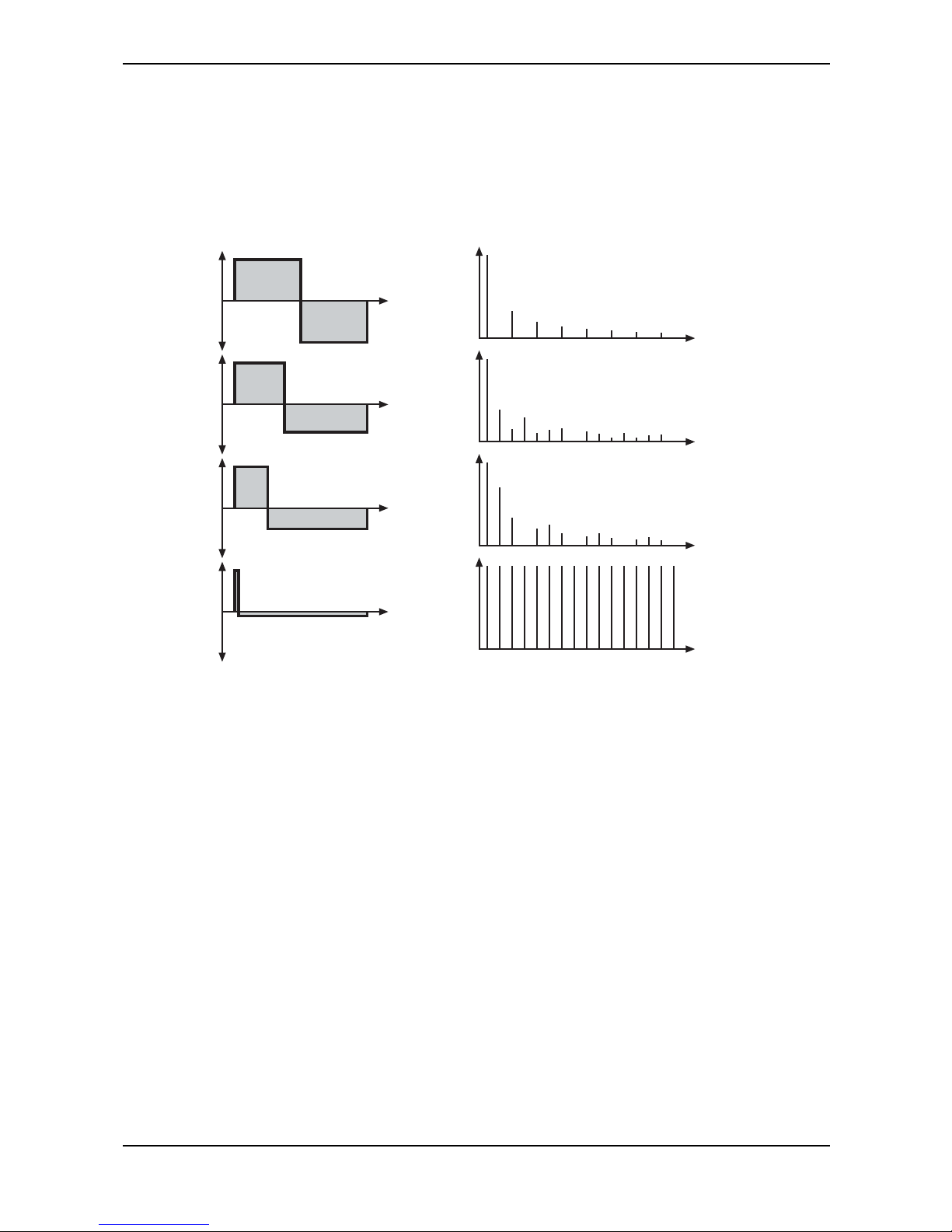
Sound Parameters – Oscillators Introduction
Waldorf microQ User´s Manual 56
The Pulse Wave
The Pulse Wave is the most versatile wave in a classic synthesizer because its shape and therefore its
harmonic content can be changed in real time. This is done by changing the width of the upper and
lower portion of the waveform cycle. These portions are called pulses, hence the name pulse width.
The width of the first pulse is used to distinguish between different pulse waves and it is measured in
percent. The following picture shows several pulse waves with different pulse widths:
13
57911 13 15
1357911 13 15
1357911 13 15
1357911 13 15
50% Pulse
(Square Wave)
25% Pulse
<1% Pulse
(Impulse)
33% Pulse
Picture 9: Additive components of Pulse wave with different pulse widths
The first thing you probably observe is that the lower part of the wave has a narrower excursion. This
is because the energy of the wider pulse is higher than the one of the narrower pulse. If this were not
compensated for in the waveform, the overall signal would have an unwanted DC offset.
As you have read in the previous chapter, the harmonic content of a 50% pulse wave is a special
case. It has a very symmetrical harmonic content, while all other pulse widths create peaks or troughs
at certain frequencies. Another special case is a pulse wave with a very narrow pulse width, in the
above picture labelled as <1%. An infinitely thin pulse creates a spectrum that has all harmonics with
equal magnitudes. In a digital synthesizer, “infinitely” necessarily means one sample.
The pulse wave is an artificial wave, which means that it doesn’t occur in nature. It was built into
synthesizers because it could create a lot of different timbres with a minimum of technical effort.
However, certain pulse widths sound very close to the timbres of acoustic (or semi-acoustic)
instruments, i.e. a guitar or bass guitar, an e-piano or even a flute.
The most powerful feature of the pulse wave is the ability change its width while sounding. This is
called pulse width modulation. When the pulse width is changed, the waveform starts to sound
thicker. This happens because the effect is very similar to what you hear when you have two
oscillators running with slightly different frequencies. They interfere and create irregular troughs in the
resulting waveforms.
Page 56
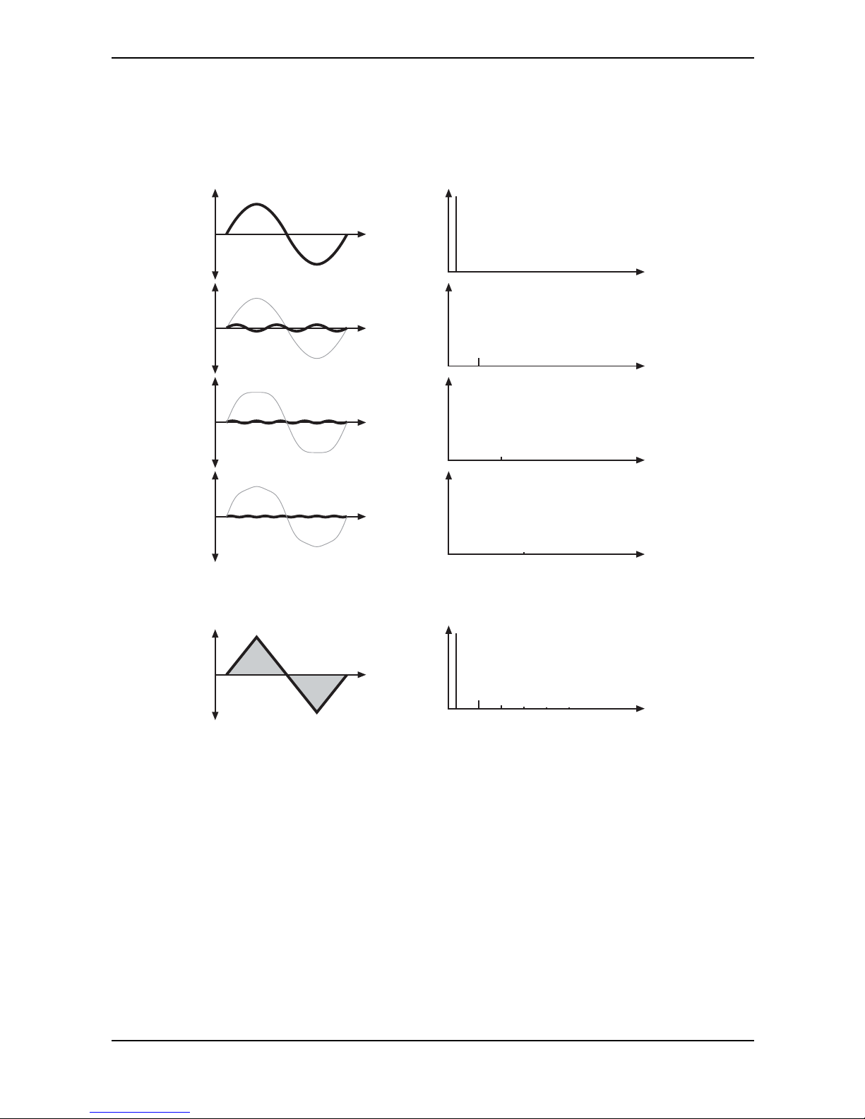
Sound Parameters – Oscillators Introduction
57 Waldorf microQ User´s Manual
The Triangle Wave
The Triangle Wave is very similar to the square wave. It is composed of the same harmonics as the
square wave, but with different magnitude ratios. The magnitude of each harmonic is divided by the
power of its number. This means that the third harmonic’s magnitude is a ninth, the fifth harmonic is a
twenty-fifth and so on. The following illustration shows the harmonic content:
13
579
Frequency
Magnitude
Time
Amplitude
+
=
1st Harmonic
Magnitude 1
5th Harmonic
Magnitude 1/25
7th Harmonic
Magnitude 1/49
Harmonics
+
+
+
.
.
11 13 15
3rd Harmonic
Magnitude 1/9
Picture 10: Additive components of the Triangle wave
The reason why the triangle wave is so popular in classic synthesizers is because it was easier to
generate than a sine wave but could be used for the same purpose. It could act as a suboscillator
wave, to emphasize certain frequencies or to frequency modulate other oscillators.
The triangle wave sounds like a woodwind instrument, i.e. a clarinet. It can also be used for mallet
instruments like vibraphone, xylophone etc.
Page 57

Sound Parameters – Oscillators Introduction
Waldorf microQ User´s Manual 58
Wavetable Synthesis in the microQ
The sound generation of the alternative waveforms (Alt1 and Alt2) of the microQ is based on
wavetable synthesis. This type of synthesis combines analog access and digital flexibility in a simple
way. Although wavetable synthesis is a form of "sample playback" in principle, you should avoid this
term because functionality, operation and results are totally different. Each of Alt1 and Alt2 contain
one wavetable with 128 Waves each.
Please keep the terms "wavetable" and "wave" in mind. Don´t confuse the two.
The following overview explains how the Wavetable Synthesis works:
A wavetable into the microQ is a table consisting of 128 waveforms. Each waveform is classified by
its own special sound character. The main difference of wavetable synthesis in comparison with other
sound generation principles is the facility not only to play one waveform per oscillator, but also to
walk through the wavetable via different modulations. Therefore you can create wavetable sweeps.
The results can be dramatic - much more so than those any sample playback based system could ever
produce. This is a unique feature of wavetable synthesis.
This principle offers powerful capabilities. To give some examples:
• Each note on a keyboard can access a different wave of the wavetable.
• Different waves can be played depending on key velocity.
• A LFO can modulate the position within the wavetable. You can create subtle to drastic
sound changes.
• User-selected controllers e.g. the mod wheel, can change the position within the
wavetable. When you turn the wheel while playing a chord, each note´s wave will be
modified intantly.
• Wavetables are perfect as the FM Source when you want to create very strange sounds.
You should keep the following sentence in mind because it describes the essential of the wavetable
synthesis:
A wavetable is a table of pointers to up to 128 waves, among which you can move at will.
If you like the sound and possibilities of wavetable synthesis, you should try out the Waldorf
Microwave II, XT or XTk. These are pure wavetable synthesizers. Also the Waldorf PPG Wave
2.V as a VST Instrument is capable of this synthesis.
Page 58
Sound Parameters – Oscillator Section
59 Waldorf microQ User´s Manual
Oscillator Section
The most important controls of the oscillators can be found in the parameter matrix. The following
picture shows the microQ’s Oscillators Section:
Octave Semi Detune FM Shape PW PWM Source
Oscillators
123
Picture 11: Oscillators Section
Selecting an Oscillator
Choose the Oscillators section with the navigation buttons, and then the Oscillator you wish to edit.
The LED of the corresponding Oscillator will light up. When keeping the left navigation button
pressed and pushing the right navigation button at the same time, you can select from on to three
available Oscillators at the same time. This allows you to edit two or three Oscillators simultaneously.
Oscillator Parameter Controls
Octave 128’…1/2’
Sets the basic pitch of the oscillator in steps of an octave. The Octave setting is shown as register
value, a common measurement based on the length of organ pipes. The reference pitch for the
oscillator is generated at MIDI note A3 (note no. 69) when Octave is set to 8’, Semi and Detune are
set to 0, Keytrack is set to 100% and no pitch modulation is applied. In this case, the oscillator’s
frequency will be the same as set in the global Tune parameter (usually 440Hz).
Set Octave to 16’ for bass sounds.
Set Octave to 8’ if you are creating typical keyboard sounds.
Set Octave to 4’ if you are programming strings or other high pitched sounds.
When you use an Oscillator to modulate other Oscillators or the Filters, experiment with the
Octave parameter. Low settings might result in periodic modulations while high settings might
add a bell character to the timbre.
Ultra-low settings like 128’ can create very nice rhythmic changes when used with the ring
modulator. If this is still not low enough, you can use the Standard Modulation Matrix to apply
MAX to the respective oscillator pitch with a negative amount.
Semi -12...+12
Sets the pitch of the oscillator in semitone steps. The standard setting for this parameter is 0, but there
are cases where different values are interesting as well.
Organ sounds often include a fifth, therefore one oscillator's semitone parameter must be set to
+7.
Lead and Solo sounds might sound interesting when you set one Oscillator to e.g. a fourth (+5
semitones).
When making ring modulated or FM sounds, try to use dissonant values, e.g. +6 or +8.
Page 59
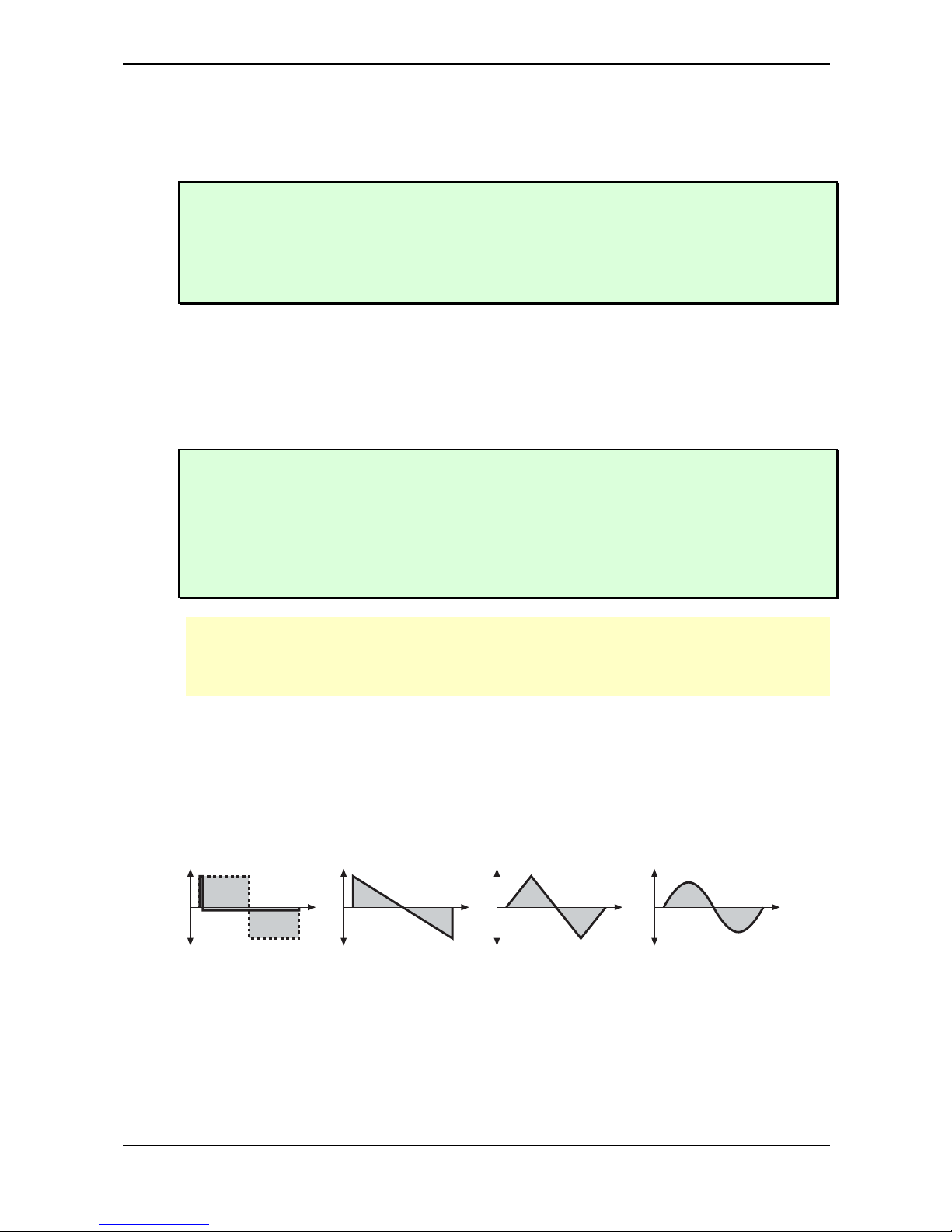
Sound Parameters – Oscillator Section
Waldorf microQ User´s Manual 60
Detune -64…+63
Fine-tunes the oscillator in steps of 1/128th of a semitone. The audible result of detuned oscillators is
a Chorus or Flanger effect. Use a positive setting for one oscillator and an equivalent negative setting
for another.
A low value of ±1 results in a slow and soft Flanger effect.
Mid-ranged settings of ±5 are perfect for pads and other fat sounding programs.
High values of ±12 or above will give a strong detune that can be used for accordions or effect
sounds.
FM 0…127
Sets the amount of frequency modulation that is applied to the oscillator by the selected FM source
in the Oscillators Edit menu. The sound will get more metallic and sometimes even drift out of tune,
especially if Oscillator 2 is used as FM Source for Oscillator 3 and Sync is activated. To avoid
unusable detune, use a triangular or sine waveform for the FM Source.
If you want to bias FM over the keyboard so that higher notes aren’t modulated as strongly as
lower notes, use the Standard Modulation Matrix and apply Keytrack to the respective
oscillator FM with a negative amount.
To change the amount of FM dynamically, use the Fast Modulation Matrix or Standard
Modulation Matrix to apply an Envelope or an LFO to the respective oscillator FM with
positive amount.
This parameter may also be found in the Oscillator Edit Menu for the sake of completeness.
FM requires a lot of CPU Power, which can lead to decrease polyphony.
Shape Off /Pulse / Saw / Tri / Sine / Alt1 / Alt2
Sets the type of waveform to be generated by the Oscillator. The parameter is called Shape instead of
“waveform”, because it doesn’t necessarily set only one waveform, but sets a specific oscillator model
that could produce a number of waveforms depending on other settings. A good example for this
behaviour is the Pulse shape. However, the term “waveform” is used interchangeably throughout the
manual. The following shapes are currently available:
Pulse
(variable Pulse Width)
Sawtooth Triangle Sine
• Off disables the selected oscillator for the purpose of increasing Polyphony. Please read the
chapter "Dynamic performance management" on page 24.
• Pulse selects the pulse waveform. A pulse waveform with a pulse width of 50% has only
the odd harmonics of the fundamental frequency present. This waveform produces a
hollow / metallic sound. If the Pulse waveform is selected, the parameters Pulsewidth and
PWM are used to change the pulsewidth of the waveform. Furthermore, the modulation
Page 60

Sound Parameters – Oscillator Section
61 Waldorf microQ User´s Manual
destinations O1PW, O2PW or O3PW gain functionality, depending on which oscillator is
set to Pulse.
• Saw selects the sawtooth waveform. A Sawtooth wave has all the harmonics of the
fundamental frequency in descending magnitude. It doesn’t have any further parameters.
This waveform is pleasing to the ear.
• Tri selects the triangular waveform. The triangle mainly consists of the odd harmonics with
very low magnitudes. It doesn’t have any further parameters.
• The Sine waveform consists of the fundamental frequency only. It has no harmonics at all.
It doesn’t have any further parameters.
• Alt1 and Alt2 are wavetable generators. Both can create a wavetable with 128 waves each.
Please refer the chapter "Wavetable synthesis". When Alt1 or Alt2 are selected, the knobs
Pulsewidth and PWM serve to select the start point of the waves. Furthermore, the
modulation sources 01PW and 02PW are active subject to which Oscillator is set to Alt. In
the Oscillators Edit Menu you additionally have Suboscillators at your disposal (please
read also „Suboscillators“ in the chapter „Oscillators Edit Menu“ on page 67). Please note
that the Wavetables are only available for Oscillators 1 and 2.
The Pulse shape can be used to create unusual synthesizer sounds and oboe like sounds.
The Saw shape can be used for basses, leads, brass and string sounds.
The Tri shape can be used for flute sounds or soft pads.
The Sine shape can be used to produce basses and electric organ sounds.
The Sine shape is also perfectly suited for ring modulation or as FM Source.
Alt1/Alt2 waves are perfect for very vivid sounds.
The tips listed here of course are only suggestions. The variety of tones among all Waveforms in
the microQ are nearly inexhaustible.
Oscillators should be set to “off” when not using them. This saves DSP Power and therefore can
contribute to increased polyphony.
PW - Pulsewidth 0…127
Sets the pulse width of the Pulse waveform. The value 0 is equivalent to a pulse ratio of <1%, the
value 127 is equivalent to 50%. You determine the start point of the wavetable at Alt1 or Alt2 with
the Pulsewidth knob, at which 0 selects the first of 128 Waveforms. If you select any waveform other
than Pulse, Alt1 or Alt2, this parameter does not have any effect The following picture illustrates the
effect of the pulsewidth parameter:
Page 61
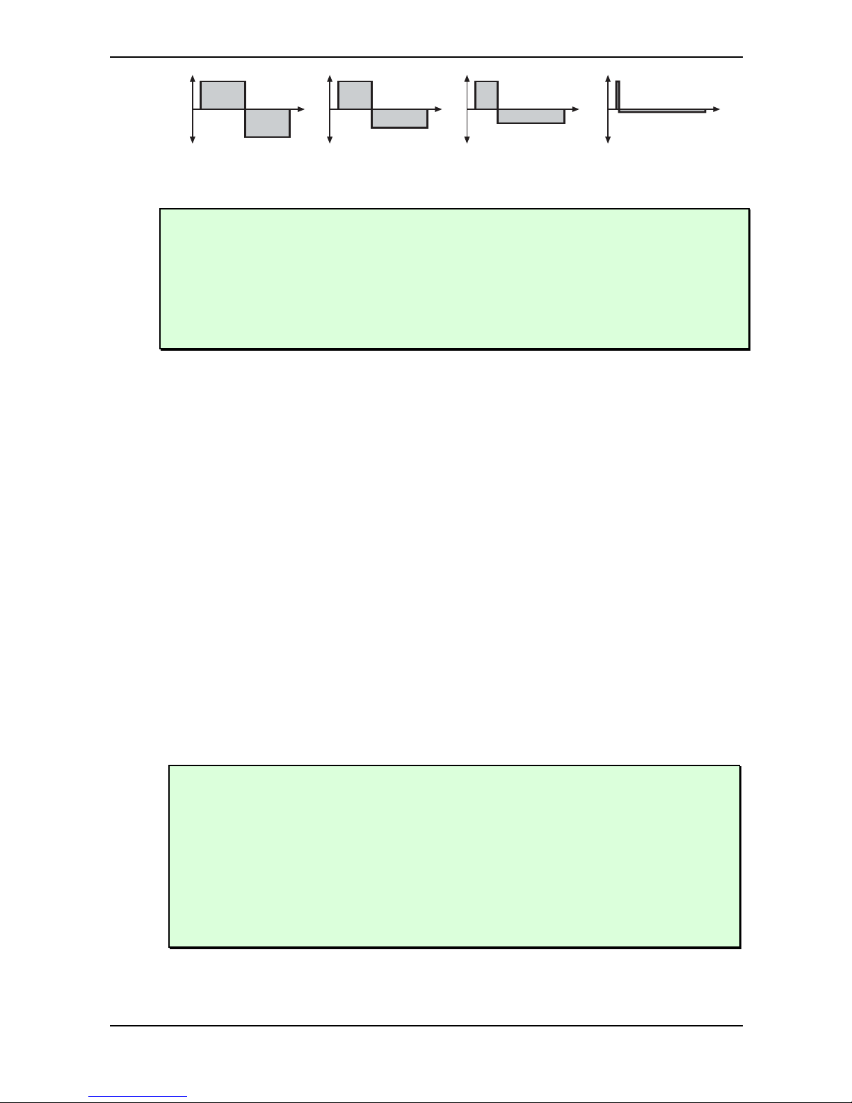
Sound Parameters – Oscillator Section
Waldorf microQ User´s Manual 62
Pulse Width 50%
(Square)
Pulse Width 33% Pulse Width 25% Pulse Width <1%
(Impulse)
Picture 12: Pulse Width parameter results
A pulse width of 50% can be used for flute sounds or very hollow bass sounds.
A pulse width of around 30% can be used for e-piano or fat bass sounds.
A pulse width of around 10% is interesting for Clavinet sounds.
Experiment with different start points for Alt1- and Alt2-Waveforms to get an overview of the
array of available Waveforms for both wavetables.
Alt1 and Alt2 waveforms
At this point we offer a few more hints and tips about the „Alternate Waveforms“:
As stated above, the Shapes Alt1 and Alt2 each contain a wavetable generator showing a few
particulars that are opposite to the normal synthesis functions. Please refer to the chapter "Wavetable
Synthesis" on page 58.
To make sure that you have access to the power of the wavetable synthsis, you should make yourself
familiar with the sound and the characteristics of both wavetables. The best way to do this is to set up
a kind of test sound to listen to the wavetables:
☞ Test program for wavetables
1. Start with an initialized sound program (please read "Init Sound" on page 136).
2. Choose Alt1 as Shape for oscillator 1, and turn down the mixer level of oscillator 2 and 3.
3. Choose the modulation wheel (Modwheel) as PWM-Source for oscillator 1.
4. Set the PWM amount to -63.
Now you can use the Modulation Wheel of your MIDI Master keyboard to sweep through the whole
wavetable. Choose Alt2 to hear how this wavetable sounds. You will notice that both wavetables
cover an extremely wide range of interesting spectral timbres, including analog, FM-like, bell-type or
vocal.
To get very lively sounds you should always use modulators when using the Wavetables of
Alt1 and Alt2.
When you like to create a wavetable sweep you should set the starting point roughly to the
desired position with Pulsewidth before programming the modulation. This procedure can
help to find the basic character of the sound being affected by the modulation.
Please note that you can use unipolar as well as bipolar modulation sources. For instance, set
the Pulsewidth Parameter to 64, nearly the middle of the wavetable, and use a slow LFO to
sweep through the whole wavetable.
Page 62

Sound Parameters – Oscillator Section
63 Waldorf microQ User´s Manual
Try out very lively sounds by using different fast modulation sources (LFOs or envelopes) on
Oscillator 1 set to Alt1 and Oscillator 2 set to Alt2, and additionally ring- and frequencymodulating the signal.
Please note that additional Suboscillators are available when using Alt1 and Alt2 (see the
chapter „Suboscillator“).
PWM -64…+63
PWM stands for pulsewidth modulation. This parameter determines the amount of modulation that is
applied to the pulsewidth of the oscillator’s square wave. If Alt1 or Alt2 is selected, PWM determines
the amount of the wavetable modulation. If you select any shape other than Pulse, Alt1 or Alt2, this
parameter does not have any effect. The modulation source that affects the pulsewidth is selected by
the source parameter described below.
PWM Source see Table “Fast Modulation Sources”
Selects the source of the pulsewidth modulation or the wavetable modulation. Common sources for
pulsewidth modulation are envelopes and LFOs, but other sources like the modulation wheel or
aftertouch can create nice effects as well.
To create a thick oscillator sound, use a triangular LFO as PWM Source with full PWM and a
Pulsewidth of around 80. This basic setting is useful for very big string and lead sounds. When
you play different notes on the keyboard, you might notice that bass notes sound more detuned
than higher notes. To avoid this behaviour, set Keytrack of the used LFO to a positive setting
between 50% and 100%.
To create a Bass sound, use a decaying Envelope as PWM Source with negative PWM and a
Pulsewidth of around 80…127. This results in a fat attack phase, especially when only one
oscillator is used for the Bass.
When you want to create a sound with a wave sweep, you should set the startpoint roughly
(Pulsewidth) at the desired wave, before you apply any modulation. This will help you to find
the basic waveform, before the effect of modulations. Note that you can apply unipolar and
bipolar modulation sources . For example, set Pulsewidth to 64, which is almost the middle of
the wavetable and apply a slow running LFO to PWM Source to sweep through the whole
wavetable.
Page 63
Sound Parameters – Oscillator Section
Waldorf microQ User´s Manual 64
Oscillator Edit Menu
The following parameters can be accessed via the display menu. Press the Edit button when you are
in the Oscillators section to activate the display menu.
O1 Keytrk|O1 BendRg
+100% | +12
01 Keytrk (Keytrack) -200%...+197%
Determines how much the pitch of the oscillator 1 depends on the MIDI note number. The reference
note for Keytrack is E3, note number 64. For positive settings, the oscillator pitch rises on notes above
the reference note, for negative settings the oscillator pitch falls by the same amount and vice versa. A
setting of +100% corresponds to a 1:1 scale, e.g. when an octave is played on the keyboard the pitch
changes for the same amount. Other settings than +100% make sense especially when using ring
modulation, FM or oscillator synchronization. Try to use values in the range 0%…+75% or even
negative settings for one oscillator while leaving the second at +100% Keytrack.
01 BendRg (Bendrange)-24…+24
Determines the intensity of the pitchbend via MIDI Pitchbend messages in semitones for oscillator 1.
O1 FM Src!01 FM Amt
Osc3 | 000
01 FM Src (FM Source) see Table “FM Sources”
Selects the source for the frequency modulation of oscillator 1.
You can create nice E-Piano sounds when you use a high pitched oscillator as FM Source and
set its Keytrack to a value between +000% and +050%.
The use of Noise is very interesting as FM Source on a high pitched oscillator playing a sine or
triangle waveform. With low FM amount, the oscillator starts to sound dirty or airy while
higher amounts create a coloured noise similar to a filter with high resonance. A side benefit is
that the filters are then still free for other purposes.
01 FM Amt (FM Amount) 0...127
Please read the "FM" in the chapter "Oscillator Parameter Controls" on page 60.
FM requires a lot of CPU Power, which can lead to decrease polyphony.
02 Keytrk (Keytrack) -200%...+197%
Determines how much the pitch of the oscillator 2 depends on the MIDI note number. For more
information please refer to "01 Keytrk".
02 BendRg (Bendrange)-24…+24
Determines the intensity of the pitchbend via MIDI Pitchbend messages in semitones for oscillator 2.
Page 64
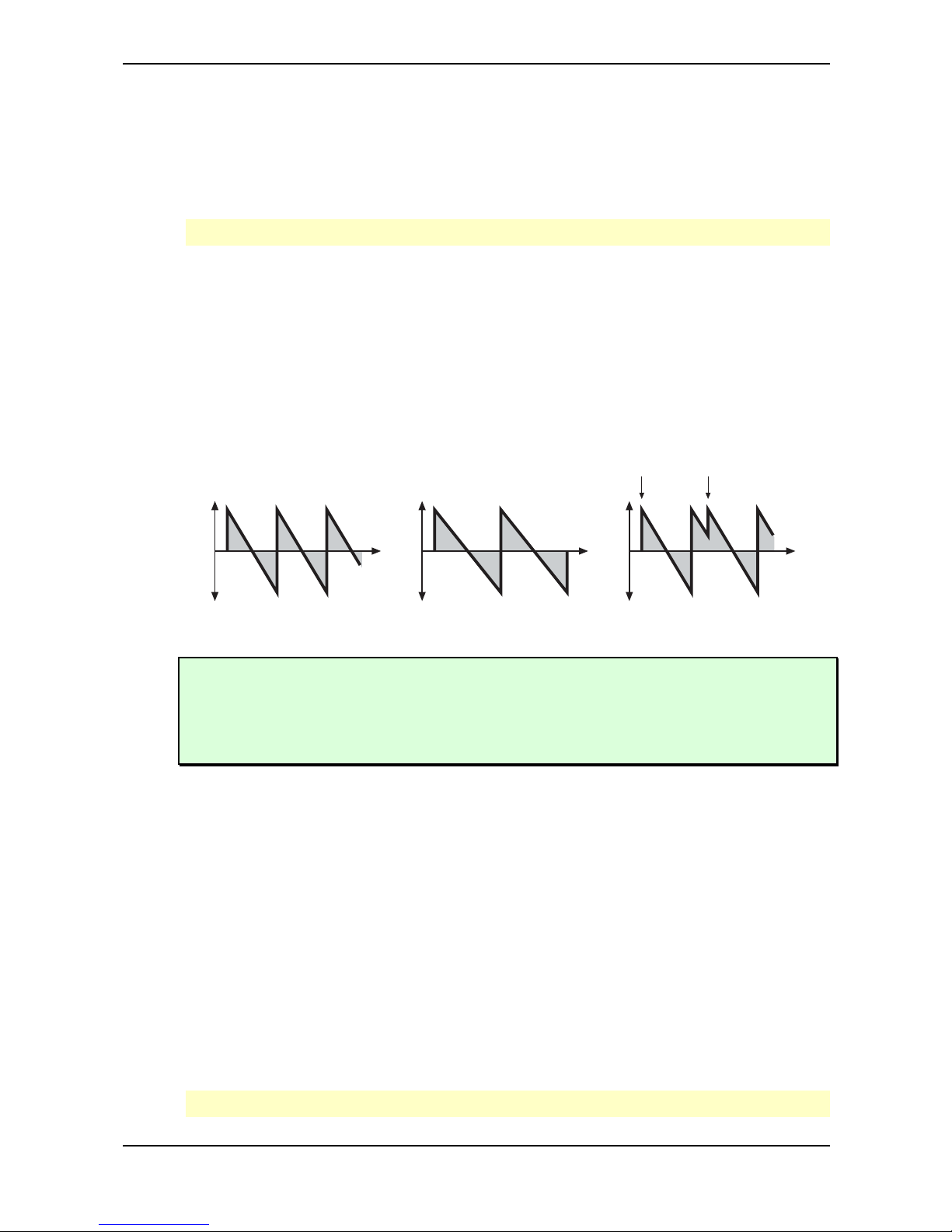
Sound Parameters – Oscillator Section
65 Waldorf microQ User´s Manual
02 FM Src (FM Source) see Table “FM Sources”
Selects the source for the frequency modulation of oscillator 2.
02 FM Amt (FM Amount) 0...127
Please read the "FM" in the chapter "Oscillator Parameter Controls" on page 60.
FM requires a lot of CPU Power, which can lead to decrease polyphony.
02 Sync off / on
Enables or disables oscillator synchronization. When enabled, Oscillator 2 acts as a slave that is
controlled by Oscillator 3, the master. Each time Oscillator 3 starts a new cycle, it sends a trigger
signal to Oscillator 2, forcing it to restart its waveform cycle, too. As a result, interesting sound effects
may be generated, especially when both oscillators are operating at different pitch settings. Using
additional pitch modulation by envelopes, LFO, or Pitch bend will lend further movement to sync
sounds. The following picture illustrates the principle of oscillator synchronization in a simplified
way:
This oscillator synced to this oscillator results in this wave
new cycle of master oscillator
Picture 13: Oscillator Sync
Use Sync for Lead or Solo sounds. Set Oscillator 2 to play one octave and 7 semitones higher,
apply an envelope to its pitch with positive amount and you get a screaming sync sound.
Sync can also be very interesting on arpeggio sounds. Apply a slow clocked LFO to Oscillator
2 pitch and the arpeggio starts to move.
03 Keytrk (Keytrack) -200%...+197%
Determines how much the pitch of the oscillator 3 depends on the MIDI note number. For more
information please refer to "01 Keytrk".
03 BendRg (Bendrange) -24…+24
Determines the intensity of the pitchbend via MIDI Pitchbend messages in semitones for oscillator 3.
03 FM Src (FM Source) see Table “FM Sources”
Selects the source for the frequency modulation of oscillator 3.
03 FM Amt (FM Amount) 0...127
Please read the "FM" in the chapter "Oscillator Parameter Controls" on page 60.
FM requires a lot of CPU Power, which can lead to decrease polyphony.
Page 65
Sound Parameters – Oscillator Section
Waldorf microQ User´s Manual 66
Pitch Src!Pitch Mod
Off | +00
Pitch Src (Pitch Source)see Table “Fast Modulation Sources”
Selects the source of the pitch modulation for all oscillators. A common source for pitch modulation
is an LFO whose strength is controlled by the modwheel or aftertouch.
To create a common pitch vibrato that is controlled by the modwheel, set Pitch Source to
LFO1*MW with Pitch Mod set to around +20.
To create a sound whose pitch glides in, set Pitch Source to a decaying Envelope with
PitchMod set to around –25.
If you want to modulate the pitch of individual oscillators, you can do so with the Fast
Modulation Matrix or Standard Modulation Matrix, which can be accessed through the
Mod Matrix section. See the respective section for details.
Pitch Mod -64…+63
Sets the amount of pitch modulation for all oscillators. Positive amounts will raise the pitch when
positive modulation is applied, e.g. by pressing aftertouch on the keyboard. Negative amounts will
lower the pitch when positive modulation is applied.
Glide
Off
Glide off / on
Enables or disables the Glide effect. "Glide" or "Portamento" describes the continuous gliding from
one note to another. This effect can be created on fretless stringed instruments or some brass
instruments (e.g. trombone). It is very common on synthesizers and used throughout all music styles.
Please note that Glide affects the pitch of all oscillators.
GlideMode! Rate
Porta | 064
Glide Mode Portamento / Fingered Portamento / Glissando / Fingeres Gliss
Determines the way the Glide effect works.
• Portamento means that a continuous glide is performed on all new notes.
• Fingered Portamento means that a continuous glide is performed only when notes are played
legato. Staccato played notes start on the exact pitch of their note.
• Glissando makes the normal Glissando effect in the same manner by changing the pitch in
semitones.
• Fingered Gliss is similar to Glissando but generates a pitchchange only when notes are
played legato.
Page 66
Sound Parameters – Oscillator Section
67 Waldorf microQ User´s Manual
Rate 0…127
Determines the glide time. Low values will give a short glide time in a range of milliseconds that gives
a special character to the sound. High values will result in a long glide time of up to several seconds
which can be useful for solo and effect sounds.
Suboscillator
01Sub Vol!Frq.divide
127 | 24
The parameters for the Suboscillator settings are only available when Alt1 or Alt2 are chosen as
Waveform. Therefore Oscillator 3 cannot create a Suboscillator. SubVol determines the volume of
the Suboscillator creating a Square Waveform. A setting of 0 corresponds to no volume. Please note
that the loudness of the Suboscillator also depends on the volume of the main oscillator. Frq.divide
determines the relative proportion of Sub- and Main oscillator frequencies. Higher values represent a
lower tuning.
When Alt-Waveforms are selected for the first two oscillators and the Suboscillators are
activated, the microQ can create up to 5 (!) oscillators per voice.
Page 67

Sound Parameters – Mixer/Routing Section
Waldorf microQ User´s Manual 68
Mixer/Routing Section
In the Mixer, you control the volumes of the oscillators, the noise generator, and an external sound
source. Ring modulation can be applied optionally to extend the microQ’s tonal range. Routing
controls the signal flow of the filters.
The following picture of the microQ’s parameter matrix shows the Mixer/Routing section:
Osc1 Balance Osc2 Balance Osc3 Balance F ilter RoutingMixer/Routing
Picture 14: Mixer/Routing Section
Mixer/Routing Parameter Controls
The most commonly used controls of the Mixer can be found in the parameter matrix.
Osc 1 / 2 / 3 0…127
Volume of the selected Oscillator(s).
Balance 1 / 2 / 3 F1 64…mid…F2 63
Determines the ratio of the selected Oscillator’s signal that is sent to the inputs of Filter 1 and Filter 2.
If set to F1 64, the signal is sent to Filter 1 only. Higher values will increase the amount of signal that
feeds Filter 2 and decrease the amount of signal that feeds Filter 1. If set to mid, both filters will
receive the same signal level. If set to F2 63, the signal is sent to Filter 2 only.
Filter Routing serial / parallel
The Routing function is one of the advanced features of the microQ. Its purpose is to control the
signal flow of the filters. In comparison with many other synthesizers where signal flow is static, the
microQ offers a more flexible configuration.
The microQ offers two independent filters and panning units. In fact, the panning units are part of the
filters in the microQ. The routing control makes it possible to change the signal flow from a parallel to
a serial filter configuration and vice versa. Furthermore, the routing control is modulatable via the
modulation matrix.
This is how the Routing section works in detail:
• The Mixer/Routing section uses two separate outputs – one connected to the input of Filter 1,
the other connected to the input of Filter 2. Each sound source, i.e. the oscillators, the ring
modulator, and the noise generator/external input has an individual Balance control in the
Mixer. By means of these controls you can determine what portion of each source’s signal is
routed to the inputs of Filter 1 and Filter 2. E.g. this makes it possible to send the signal of
Oscillator 1 and 2 to Filter 1 and the ring modulation signal to Filter 2.
• The output of Filter 1 is split up into two paths. The Routing knob determines the ratio of the
signals for each path.
• When the Routing parameter is set to serial, the whole output signal of Filter 1 is routed to
the input of Filter 2, and added to the amount of signal that is already coming from the Mixer
through its dedicated output. This setting is equivalent to a serial connection of the two filters.
Page 68
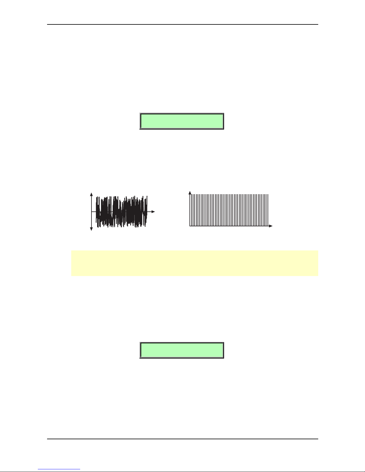
Sound Parameters – Mixer/Routing Section
69 Waldorf microQ User´s Manual
• When the Routing parameter is set to parallel, the whole output signal of Filter 1 is routed to
the filter’s panning unit. This setting is equivalent to a parallel routing of two filters, each
filtering the input signals independently.
• After passing the panning units, both signals are summed up again and sent to the Amplifier
and FX sections.
Mixer/Routing Edit Menu
The following parameters can be accessed via the Mixer/Routing Edit menu. If you are in the
Mixer/Routing section press the Edit button to activate this display menu.
N/E Mix ! N/E Bal
127 | F1 64
N/E Mix – Noise/External Mix / Ext. 0…127
Volume of the noise generator respectively the external sound source connected to the stereo
External In jack. This control behaves differently depending on the setting of N/E Select F1/2
feed in the Mixer Edit menu. Noise is a fundamental source for any kind of analog-type percussion.
Also, wind and other sound effects can be created by using the noise generator.
110 100 1000 10000
Frequency (Hz)
Magnitude
Time
Amplitude
Picture 15: Noise
Please note that if you use an external sound source, you still have to trigger the microQ’s
envelopes to get the signal passed through. So you have to generate MIDI notes from a
connected sequencer or the internal arpeggiator to hear the audio signal.
N/E Bal - Noise / Ext. Balance F1 64…mid…F2 64
Determines how loud the signals set up in N/E Select F1/F2 feed are sent to the inputs of Filter 1
and Filter 2. Noise / Ext. Balance behaves differently from the other Balance controls. It doesn’t
move the signal between Filter 1 and Filter 2 but controls the loudness ratio between the two signals
set up in N/E Select F1/F2 feed. The signal set up in F1 feed is always sent to Filter 1 while the
signal set up in F2 feed is always sent to Filter 2.
N/E Select F1/2 feed
Noise | ExtLeft
N/E Select F1 / F2 Feed Noise / ExtLeft / ExtRight / ExtL+R
Sets the input signal sources that are fed into filter 1 and filter 2.
Please note that the N/E Balance control behaves differently compared with the other Balance
controls. N/E Balance only affects the input levels but doesn't shift the signals between the filters. F1
Feed is always routed to Filter 1 while F2 Feed is always routed to Filter 2.
The available sources are:
Page 69
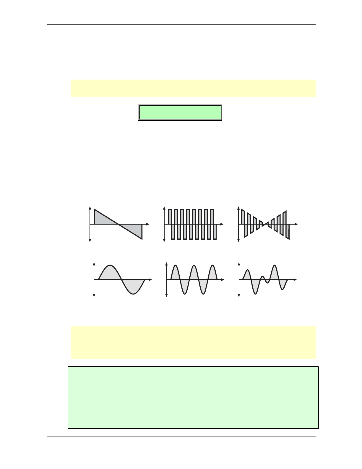
Sound Parameters – Mixer/Routing Section
Waldorf microQ User´s Manual 70
• Noise selects the Noise Generator as input for the respective filter.
• ExtLeft selects the Left input signal as input for the respective filter.
• ExtRight selects the right input signal as input for the respective filter.
• ExtL+R feeds the summed signal of the left and right input into the respective filter.
Noise needs CPU Power which results in decreased polyphony. If you don´t need the noise
generator set N/E Select F1/F2 feed not to Noise.
Ringmod !Ring Bal
000 ! F1 64
RingMod - Ringmodulation 0…127
Volume of the ring modulation between Oscillator 1 and 2. From a technical point of view ring
modulation is the multiplication of two oscillators’ signals. The result of this operation is a waveform
that contains the sums and the differences of the source frequency components. Since the ring
modulation generates disharmonic components, it can be used to add metallic distorted sound
characteristics. This is useful e.g. when generating synth percussion. Please note that in a complex
waveform all harmonic components behave like interacting sine waves, resulting in a wide spectral
range of the ring modulated sound. The following pictures show the results of a saw wave
ringmodulated with a square wave and two ringmodulated sine waves:
This Sawtooth wave ringmodulated with this Square wave results in this wave
Picture 16: Ring Modulation of a Sawtooth and a Square wave with different frequencies.
A Sine wave with frequency 1 ringmodulated with a Sine wave with
frequency 2.5 (1 octave + 4 semitones)
results in this wave
Picture 17: Ring Modulation of two Sine waves with different frequencies.
Ring Modulation can result in unwanted low frequencies when the pitches of oscillator 1 and 2
don’t differ very much. This is logical because when you use i.e. one oscillator set to 100Hz
and the second set to 101Hz, the resulting ring modulation is 201Hz and 1Hz, and 1Hz is very
low.
Ring Modulation can be very interesting when a slow pitch modulation is applied to one
oscillator, i.e. a decaying Envelope. This creates spacy effect sounds.
For an E-Piano sound, you might apply Ring Modulation when one high pitched oscillator’s
Keytrack is lowered to i.e. 50%.
If you turn down the pitch of one oscillator markedly, you can get an effect very similar to
Amplitude modulation. Use this for sounds with a periodic element if you wish.
Page 70

Sound Parameters – Mixer/Routing Section
71 Waldorf microQ User´s Manual
RingMod Balance F1 64…mid…F2 63
Determines the ratio of the ring modulator’s signal that is sent to the inputs of Filter 1 and/or Filter 2. If
set to F1 64, the signal is sent to Filter 1 only. Higher values will increase the amount of signal that
feeds Filter 2 and decrease the amount of signal that feeds Filter 1. If set to mid, both filters will
receive the same signal level. If set to F2 63, the signal is sent to Filter 2 only.
Page 71
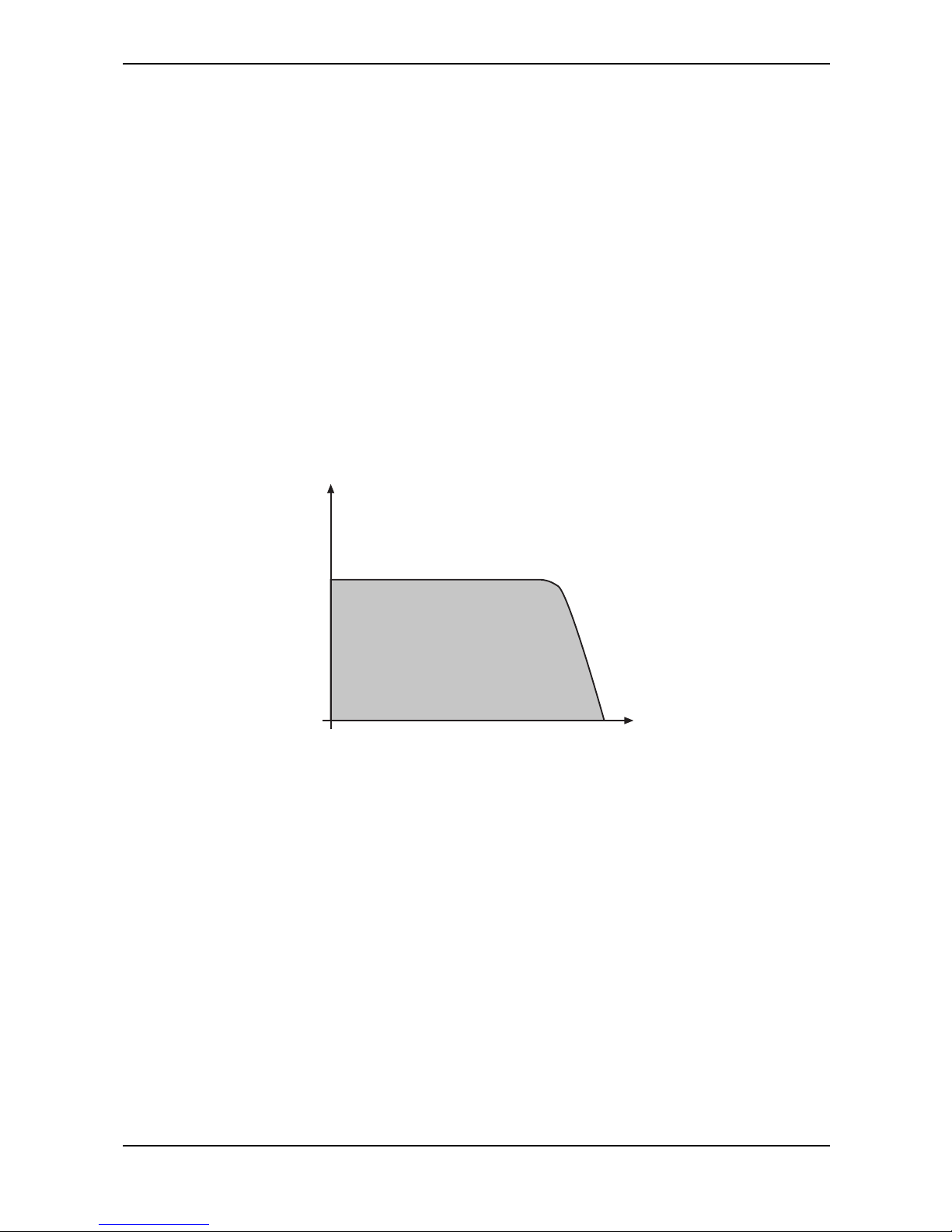
Sound Parameters – Filter Introduction
Waldorf microQ User´s Manual 72
Filter Introduction
Once the audio signal leaves the mixer, it is sent to the filters. The microQ has two independent filter
units, each with its own individual settings. The signal flow in the filters can be controlled via the
Routing function. The filters are components that have significant influence on the microQ’s sound
characteristics.
For a detailed description of the different filter types that are available in the microQ, see the section
“Filter Types” on page 78. For now, we’ll explain the basic function of a filter discussing the type used
most commonly in synthesizers: the low pass filter.
The low pass filter type dampens frequencies that lie above a specified cutoff frequency. Frequencies
below this threshold are hardly affected. The frequency below the cutoff point is called the pass band
range, the frequencies above are called the stop band range. The microQ’s filter dampens frequencies
in the stop band with a certain slope. The slope can be 12dB or 24dB per octave. This means that the
level of a frequency that lies an octave above the cutoff point will be 12dB or 24dB less than those
frequencies of the signal that fall into the pass band. The following picture shows the basic principle
of a low pass filter:
Frequency
Level
Cutoff
Picture 18: Low Pass Filter principle
To give you an idea of the extent of damping, consider this example of a low pass filter: A reduction
of 24dB reduces the original level one octave above the cutoff point by approx. 94%. The damping
factor two octaves above the cutoff point reduces the original level by more than 99%, which in most
cases means this portion of the signal is no longer audible.
The microQ’s filter also features a resonance parameter. Resonance in the context of a low, band or
high pass filter means that a narrow frequency band around the cutoff point is emphasized. The
following picture shows the effect of the resonance parameter on the filter’s frequency curve:
Page 72
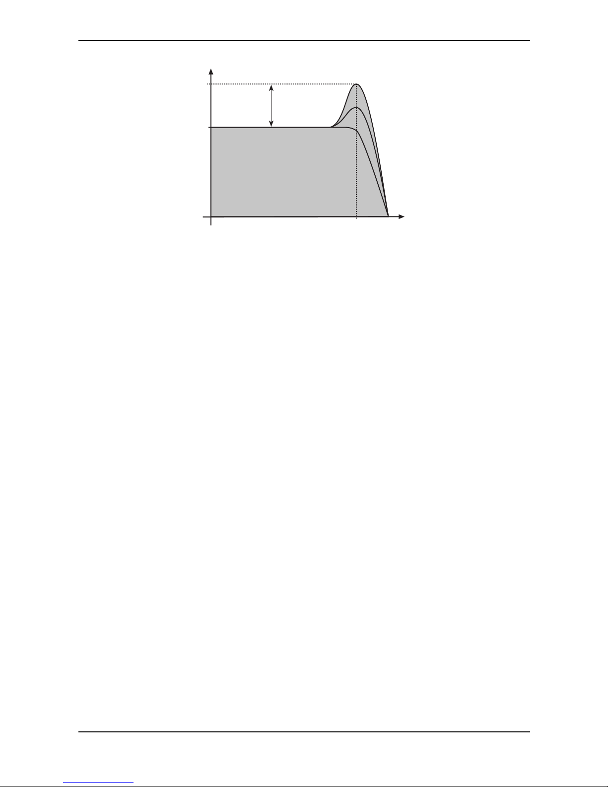
Sound Parameters – Filter Introduction
73 Waldorf microQ User´s Manual
Frequency
Level
Cutoff
Resonance
Picture 19: Low Pass Filter Resonance
If the resonance is raised to a great extent, then the filter will begin self-oscillation, i.e. the filter
generates an audible sine wave even when it does not receive an incoming signal.
Page 73
Sound Parameters – Filter Section
Waldorf microQ User´s Manual 74
Filter Section
The most commonly used controls of the filters can be found in the parameter matrix.
The following picture of the microQ’s parameter matrix shows the Filter section:
Cutoff Keytrack Resonance Drive Env Velocity T ype Panning
Filters
12
Filter section
Selecting and Editing Filters
Before you make any edits to the filters, you must select for editing either Filter 1, Filter 2, or both.
This can be done by pressing the left or right navigation button when the Filter section is selected.
Push the buttons until both Filter LED light up. The two LED of the Filter section indicate which filter
is selected for editing.
If both filters are selected for editing, moving any control will alter the setting of the corresponding
parameter for Filter 1 and Filter 2. Please note that all edits are relative. Therefore, the relationship of
the parameters will be retained. E.g. the display may look like this when turning the Cutoff knob:
[F1 Cutoff 80]
[F2 Cutoff 93]
In the given example, turning the Cutoff control two steps clockwise will result in the following:
[F1 Cutoff 82]
[F2 Cutoff 95]
If the value range of one parameter is reached, e.g by turning Cutoff clockwise until 127 is set for
Filter 1, the relationship is no longer retained. In this case, the cutoff of Filter 1 will keep its maximum
value while Filter 2’s cutoff is still increased by turning the knob.
The scenario is different when you move the Type knob. If both filters are selected for editing
and Type is altered, the same filter type is assigned to Filter 1 and Filter 2. This takes place
because altering selection parameters relatively does not make any sense.
Filter Parameter Controls
Cutoff 0…127
Controls the cutoff frequency for the low pass and high pass filter types, the center frequency for the
band pass and notch filter types, and the delay length of the comb filter types.
• When a low pass is selected via the Type parameter, all frequencies above the cutoff
frequency are damped.
• When a high pass type is selected, all frequencies below the cutoff frequency are damped.
• When a band pass type is selected, only frequencies near the cutoff setting will be passed
through.
• When a notch type is selected, the frequencies near the cutoff frequency are damped.
• When a comb type is selected, the frequencies near the cutoff frequency are emphasized
(comb+) or attenuated (comb-).
Page 74

Sound Parameters – Filter Section
75 Waldorf microQ User´s Manual
You can bring more movement into the sound by modulating the cutoff frequency via the LFOs, the
envelopes or the Keytrack parameter of the filter. At a value of 64 and a Resonance value of 114, the
filter oscillates with 440Hz, which is equal to A3 (the Comb+ type oscillates one octave higher).
Tuning is scaled in semitone steps. When Keytrack is set to +100%, the filter can be played in a
tempered scale.
Keytrack -200%…+197%
Determines how much the cutoff frequency depends on the MIDI note number. The reference note
for Keytrack is E3, note number 64. For positive settings, the cutoff frequency rises on notes above the
reference note, for negative settings the cutoff frequency falls by the same amount, and vice versa. A
setting of +100% corresponds to a 1:1 scale, so e.g. when an octave is played on a keyboard the
cutoff frequency changes by the same amount. If you want to play the filter in a tempered scale, e.g.
for a solo sound with self-oscillation, set the value to +100%. On most bass sounds lower settings in
the range +50…+75% are optimal to keep the sound smooth at higher notes.
Resonance 0…127
Controls the emphasis of the frequencies around the cutoff point. Use lower values in the range of
0…80 to give more brilliance to the sound. At higher values of 80…113 the sound gets the typical
filter character with a strong boost around the cutoff frequency. When the setting is raised to values
above 113, the filter starts to self-oscillate, generating a pure sine wave. This feature can be used to
create analog-style effects and percussion-like electronic toms, kicks, zaps etc.
Drive 0…127
Determines the amount of saturation that is added to the signal. If set to 0, no saturation will be added
or, in other words, the signal will remain clean. Lower values will add some harmonics to the signal,
resulting in a warm character. Increasing the value will bring in more and more distortion, suitable for
harder lead sounds and effects.
Env (Filter Envelope Amount) -64…+63
Determines the amount of influence the filter envelope has on the cutoff frequency. For positive
settings, the filter cutoff frequency is increased by the modulation of the envelope, for negative
settings, the cutoff frequency is decreased. Use this parameter to change the timbre of the sound over
time. Sounds with a hard attack usually have a positive envelope amount that makes the start phase
bright and then closes the filter to get a darker sustain phase. String sounds, on the other hand, usually
use a negative envelope amount that gives a slow and dark attack before the cutoff rises in the sustain
phase.
Velocity (Filter Velocity) -64…+63
Determines the amount of influence the filter envelope has on the cutoff frequency, based on key
velocity. This parameter works similarly to the Env parameter with the difference that its intensity is
velocity based. Use this feature to give a more expressive character to the sound. When you hit the
keys smoothly, only minimal modulation is applied. When you hit them harder, the modulation
amount also gets stronger. The following picture illustrates the functionality of this parameter:
Page 75
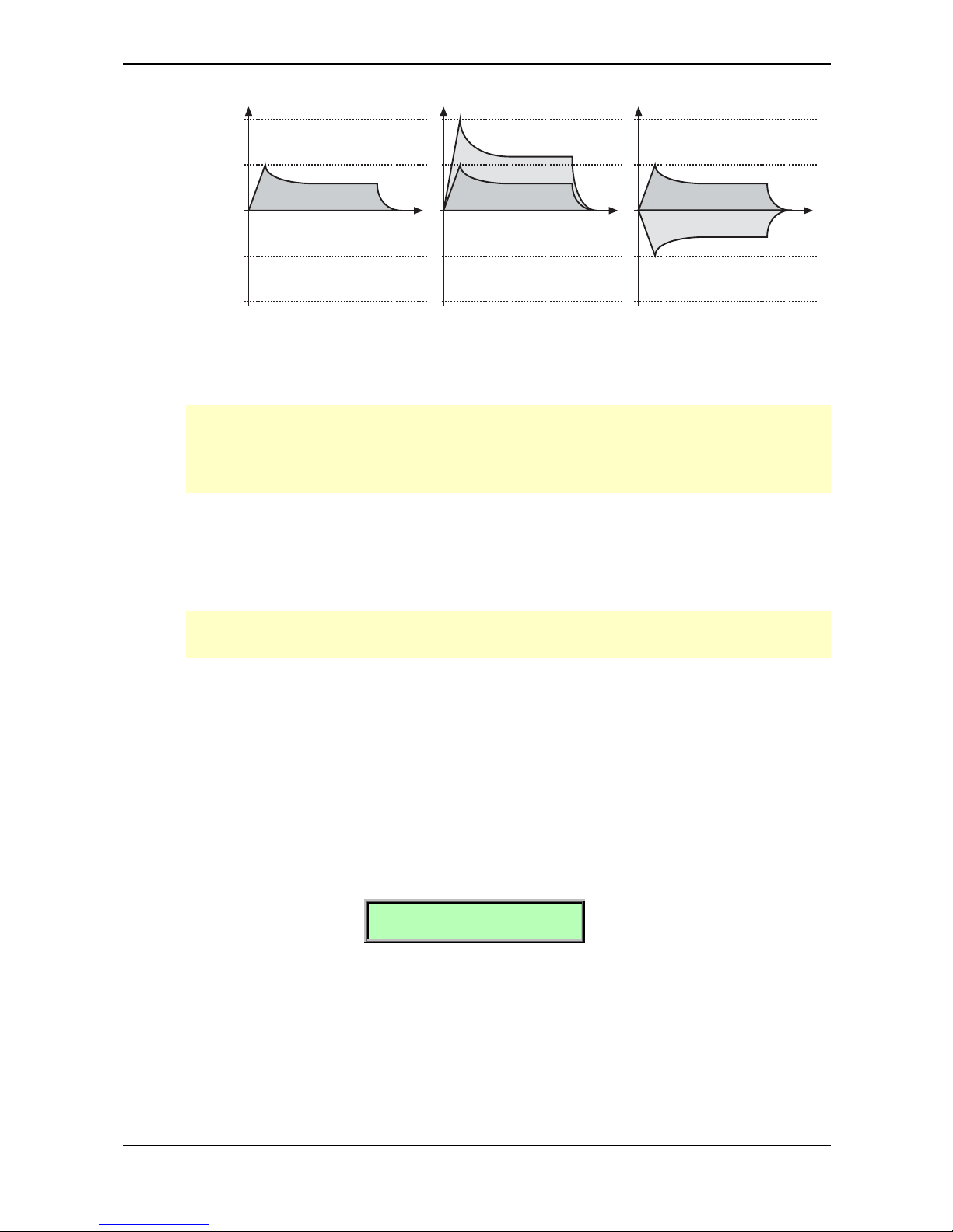
Sound Parameters – Filter Section
Waldorf microQ User´s Manual 76
Time
Envelope Depth
100%
Env Parameter = +32
Velocity Parameter = 0
Key Velocity = 1…127
Env Parameter = +32
Velocity Parameter = +32
Env Parameter = +32
Velocity Parameter = -64
0%
-100%
50%
-50%
Key Velocity = 1
Time
Key Velocity = 127
Key Velocity = 1
Time
Key Velocity = 127
Picture 20: Envelope depth influence of different Velo parameter settings
The overall modulation applied to the filter’s cutoff frequency is calculated as the sum of both
the Env and Velocity parameters. Therefore you should always bear this total in mind,
especially when the filter does not behave as you expect. You can also create interesting effects
by setting one parameter to a positive and the other to a negative amount.
Type see chapter “Filter Types”
Selects the filter type. Further information on the different filter types is given at the end of this
chapter.
Usage of Filters (especially comb filters) requires DSP Power, and therefore can reduce the
available polyphony. A filter switched to “ Bypass” doesn’t need any DSP Power at all.
Panning left 64…center…right 63
Determines the position in the stereo panorama. When the setting is left 64, the sound is panned far
left; when the setting is right 63, it is panned far right. If you want to situate the sound in the middle of
the stereo panorama, use the center setting. To give further movement to the sound, set this parameter
to a basic value and apply some modulation to it via the PanMod parameter in the Filter Edit menu.
Filter Edit Menu
The following parameters can be accessed via the Filter Edit menu. If you are in the Filter section
press the Edit button to activate this display menu.
F1 ModSrc! F1 Mod
LFO1 | +00
F1 ModSrc – Filter 1 Cutoff Mod Source see Table “Fast Modulation Sources”
Selects the source of the cutoff modulation for Filter 1.
F1 Mod – Filter 1 Cutoff Modulation -64…+63
Controls the amount of cutoff modulation for Filter 1. Positive amounts will increase the cutoff
frequency when positive modulation is applied, e.g. by pressing the aftertouch on the keyboard.
Negative amounts will decrease the cutoff frequency when positive modulation is applied.
Page 76
Sound Parameters – Filter Section
77 Waldorf microQ User´s Manual
F1 FM Src!F1 FM Amt
Off | Off
F1 FM Src – Filter 1 FM Source see Table “FM Sources”
Selects the source of the frequency modulation for Filter 1.
F1 FM Amt – Filter 1 FM Amount Off, 0…127
Sets the amount of frequency modulation that is applied to the filter by the selected source for Filter 1.
FM needs a lot of CPU power, which results in decreased polyphony.
F1 PanSrc!F1 PanMod
Off | +00
F1 PanSrc – Filter 1 Panning Source see Table “Fast Modulation Sources”
Selects the source of the panorama modulation for Filter 1.
F1 PanMod – Filter 1 Panning Modulation -64…+63
Determines the amount of panorama modulation for Filter 1.
F2 ModSrc! F2 Mod
LFO1 | +00
F2 ModSrc – Filter 2 Cutoff Mod Source see Table “Fast Modulation Sources”
Selects the source of the cutoff modulation for Filter 2.
F2 Mod – Filter 2 Cutoff Modulation -64…+63
Controls the amount of cutoff modulation for Filter 2. Positive amounts will increase the cutoff
frequency when positive modulation is applied, e.g. by pressing the aftertouch on the keyboard.
Negative amounts will decrease the cutoff frequency when positive modulation is applied.
F2 FM Src!F2 FM Amt
Off | Off
F2 FM Src – Filter 2 FM Source see Table “FM Sources”
Selects the source of the frequency modulation for Filter 2.
F2 FM Amt – Filter 2 FM Amount Off, 0…127
Sets the amount of frequency modulation that is applied to the filter by the selected source for Filter 2.
FM needs a lot of CPU power, which results in decreased polyphony.
Page 77
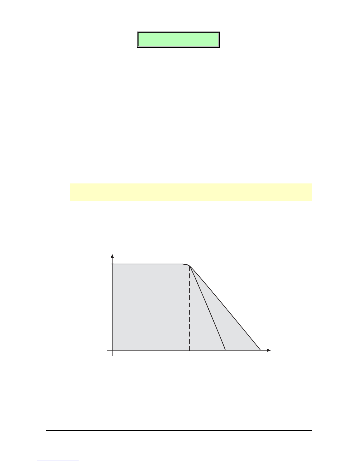
Sound Parameters – Filter Types
Waldorf microQ User´s Manual 78
F2 PanSrc!F2 PanMod
Off | +00
F2 PanSrc – Filter 2 Panning Source see Table “Fast Modulation Sources”
Selects the source of the panorama modulation for Filter 2.
F2 PanMod – Filter 2 Panning Modulation -64…+63
Determines the amount of panorama modulation for Filter 1.
Filter Types
This paragraph describes the microQ’s different filter types. Most types are based on traditional low
pass, high pass or band pass structures.
Bypass
Use this setting to bypass the filter. This is useful if you want to disable the filter temporarily and listen
to the oscillators’ pure signals.
With this setting the microQ doesn’t need any DSP Power for this operation. If you do not want
to use Filter 1 or Filter 2 then switch them to “Bypass”.
24dB Low Pass and 12dB Low Pass
The low pass types 24dB LP and 12dB LP are suitable for most normal applications. Use the 24dB
slope if you want to create sounds with a typical audible filtered character; use the 12dB slope if you
want to get softer results.
Frequency
Level
Cutoff
24dB/Oct 12dB/Oct
Picture 21: Low Pass Filter Type
Page 78
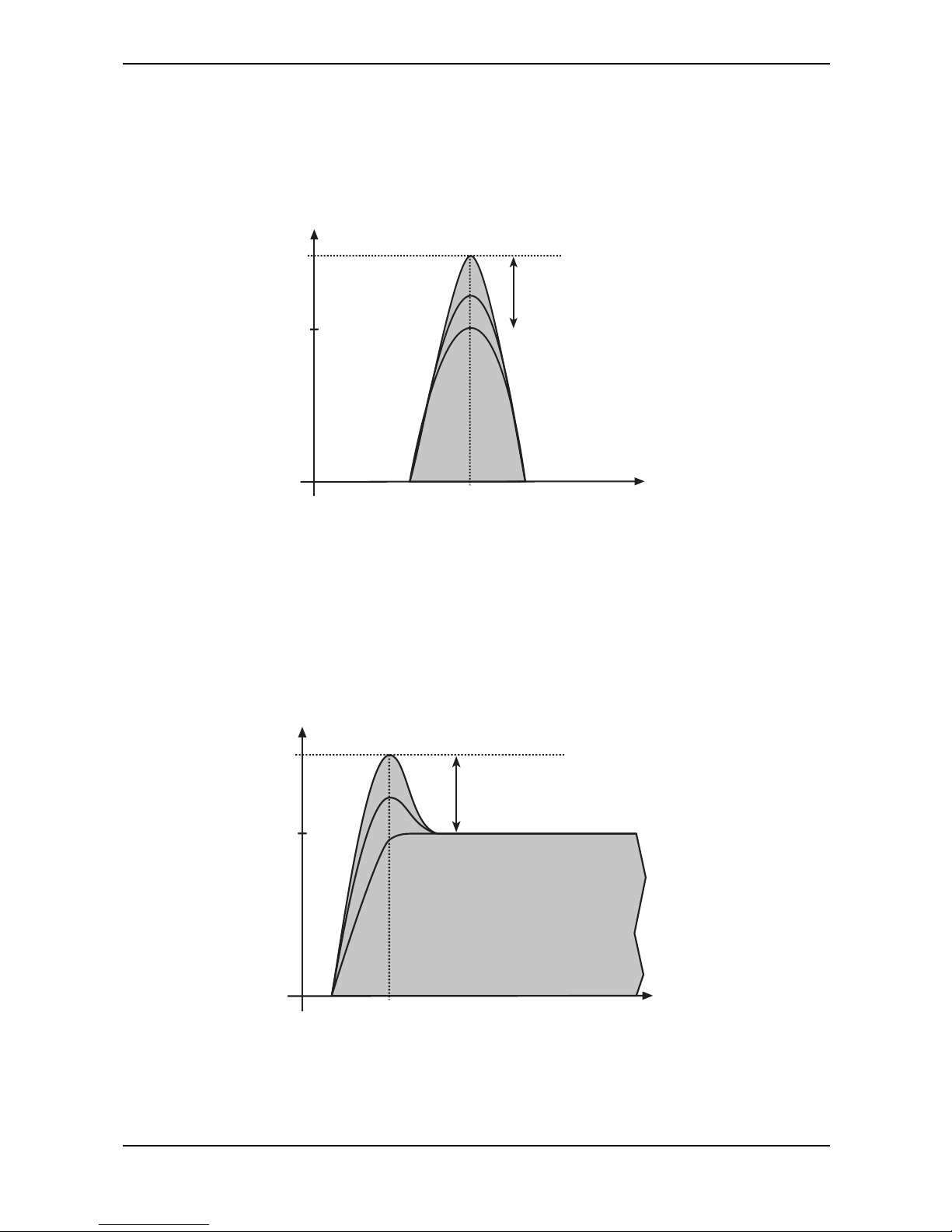
Sound Parameters – Filter Types
79 Waldorf microQ User´s Manual
24dB Band Pass and 12dB Band Pass
The band pass filters 24dB BP and 12dB BP remove frequencies both below and above the cutoff
point. As a result, the sound character gets thinner. Use these filter types when programming effect
and percussion-like sounds.
Frequency
Level
Cutoff
Resonance
Picture 22: Band Bass Filter Type
24dB High Pass and 12dB High Pass
The high pass filters 24db HP and 12dB HP are useful to thin out a sound’s bass frequencies. This
may also give interesting results in conjunction with cutoff frequency modulation. By doing this you
can e.g. "fly-in" a sound starting at its high harmonics and then coming up to its full frequency range.
Use the 24dB slope if you want to create sounds with a typical audible filtered character; use the
12dB slope if you want to get softer results.
Frequency
Level
Cutoff
Resonance
Picture 23: High Pass Filter Type
Page 79
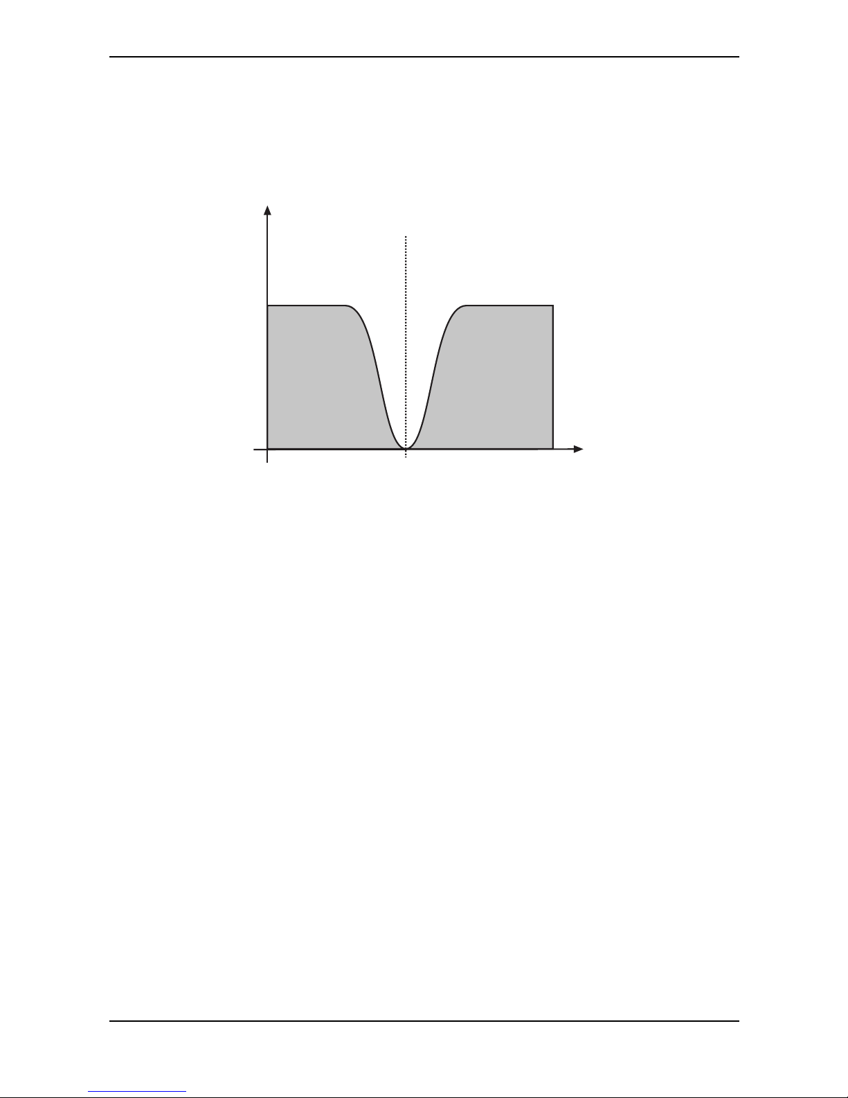
Sound Parameters – Filter Types
Waldorf microQ User´s Manual 80
24dB Notch and 12dB Notch
The notch filters 24db Notch and 12dB Notch are the opposites of the band pass types. They dampen
frequencies around the cutoff point. Frequencies below or above the cutoff point are passed through.
Use these filter types for programming effect sounds.
Frequency
Level
Cutoff
Picture 24: Notch Filter Type
On Notch filter types, the Resonance parameter is almost useless by definition because the resonance
frequency is exactly the frequency that is blocked by the filter. However, you will still be able to hear
slight differences when you change the Resonance because of phase changes. Anyway, the effect isn’t
that spectacular.
Page 80

Sound Parameters – Filter Types
81 Waldorf microQ User´s Manual
Comb+ and Comb-
The Comb filter types differ from the other filter types greatly, because they don’t actually damp any
part of the signal, but instead add a delayed version of the input signal to the output. What exactly is
a Comb filter?
A Comb filter is basically a very short delay that can be controlled in length and feedback. The delay
time is so short that you can’t hear its individual taps but a colorization of the original signal created
by peaks or holes in the frequency spectrum. The frequency of the colorization is set by the delay
length, which is controlled in the microQ through Cutoff, while the amount of colorization is set by
the Comb filter feedback, which is controlled in the microQ through Resonance.
Frequency
Level
Cutoff determines number of teeth
Resonance
Picture 25: Comb + Filter Type
Frequency
Level
Cutoff determines number of teeth
Resonance
Picture 26: Comb – Filter Type
So, as with all other filter types, the Comb filter is controlled with two parameters:
• Cutoff controls the delay length.
• Resonance controls the feedback depth.
Now, what sound can a comb filter produce? Here are some examples:
The Comb filter as a Chorus
This is the most basic way to use the Comb filter. A Chorus in fact is made of one or several Comb
filters, so this is an easy task to set up manually.
Page 81
Sound Parameters – Filter Types
Waldorf microQ User´s Manual 82
☞ To set up the Comb filter to produce a Chorus:
1. Select the Comb+ filter type for the desired filter.
2. Set Cutoff to a medium value.
3. Set Resonance, Drive, Filter Keytrack and any other modulation to 0.
4. Select an LFO as Mod Source.
5. Set Mod to a medium positive or negative amount.
6. Adjust the LFO to generate a slow triangle oscillation.
7. Fine tune Cutoff, Mod and LFO Speed until you get the desired Chorus effect.
You can also use both filters to create a Chorus and pan them to different stereo positions.
You can also pan the original, i.e. low pass filtered signal, to one stereo side and route 50%
into Filter 2, producing a Chorus effect that is panned to the other stereo side.
You might ask why you should use a Comb filter type to produce Chorus instead of using the FX
section of the microQ. Here are some reasons:
• The FX sections remain free for other purposes. Also, in Multi Mode, the Comb filter works no
matter on which Instrument you use it.
• The Comb filter works per voice rather than per Instrument. This means that each voice has
its own Chorus and therefore could generate a different Chorus effect. You can easily hear
this when you change LFO Keytrack or Filter Keytrack. Now, each voice sounds with a
different Chorus speed or frequency.
• You have full control over MIDI of all parameters that make up the Chorus effect, by using
Control messages.
The Comb filter as a Flanger
A Flanger is almost the same as a Chorus. The only difference is that it has feedback circuitry to
change the depth of the Flanger effect.
☞ To set up the Comb filter to produce a Flanger:
1. Adjust the filter as described in the Chorus paragraph above.
2. Turn up Resonance to create the typical Flanger sound.
3. Gradually lower LFO Speed to create slow Flanger sweeps.
4. Select either Comb+ or Comb- to change the character of the Flanger.
Set up Mod Source to Modwheel to change the Flanger effect manually.
Use the Filter Envelope with positive or negative amount to create a “one time sweep” that is
triggered at Note On.
Use Filter Keytrack with an amount of 100% to create really different flangings depending on
the Note you play.
Page 82
Sound Parameters – Filter Types
83 Waldorf microQ User´s Manual
The Comb filter used to simulate a string or a tube
The Comb filter is one of the most basic building blocks of “Physical Modeling”, which is the term for
an algorithmic description of an acoustic instrument. The microQ is definitely not meant to replace a
good physical modeling synthesizer, so you shouldn’t expect to get a perfect emulation of an acoustic
instrument like a trumpet or a violin out of the microQ. However, the Comb filter enables you to
create abstractions of those sounds that can be played expressively.
To do so, you have to understand that the Comb filter is the part that actually sets the pitch of the
resulting sound; the oscillators or the noise generator are only used to trigger the Comb filter
somehow. When you play with the Comb filter, you can hear that it emphasizes or attenuates certain
frequencies depending on the setting of Cutoff and Resonance.
When you set Resonance to a very high value, you will notice that the Comb filter oscillates heavily,
and that’s the key to using it as a tone generator. When you set Filter Keytrack to +100%, you can
play the Comb filter musically.
Now you need to know how to set up Cutoff. Filter Cutoff is scaled in semitone steps, and you only
have to find the Cutoff value where the filter oscillates with standard pitch. The following table gives
you these settings:
Oscillator Comb+ Comb-
64’ 11 23
32’ 23 35
16’ 35 47
8’ 47 59
4’ 59 71
2’ 71 83
Table 9: Comb Filter Cutoff settings
If you need other tunings, just keep in mind that Cutoff is changed in semitones, so if you increment
Cutoff by 12, the filter oscillates one octave higher, and so forth.
☞ To set up the Comb filter to produce a tone:
1. Select either Comb+ to produce a string-like tone or Comb- to produce a tube-like tone.
2. Turn up Resonance to around 114 to 127.
3. Turn up Filter Keytrack to +100% to have Filter Cutoff change with equal-tempered
scaling.
4. Set Cutoff to 23, 35, 47 or 59 to have it oscillating in the same pitch as the oscillator´s
usually tuning. Please note that Comb+ oscillates one octave higher than Comb-.
5. Feed the Comb filter with a signal of any kind. The incoming signal’s pitch isn’t important
for the resulting tuning, but both pitch and timbre of the input signal affect the timbre of the
Comb filter output sound greatly.
Try to experiment with all kinds of input signals, i.e. different oscillator settings, noise,
combinations of both and the like.
Also try to set up envelopes to control the levels of the input signal, i.e., use a short percussive
signal that only triggers the comb filter briefly. The filter then oscillates to produce the resulting
tone.
Page 83
Sound Parameters – Amp/FX/Arp Section
Waldorf microQ User´s Manual 84
Amp/FX/Arp Section
This section is the last of the microQ’s signal routing. Its purpose is to set the volume of the sound and
contains the effect settings. Furthermore this section controls the arpeggiator.
The following picture of the microQ’s Parameter Matrix shows the Amp/FX/Arp section:
Volume V elocity FX1 Mix FX2 Mix Arp Mode Range Tempo Clock
Amp/FX/Arp.
Picture 27: Amp/FX/Arp section
Amplifier Parameter Controls
To understand the operation of this unit, it is important to know that the Amplifier Envelope is always
acting as a modulation source for the volume. This means that an audio signal can only pass through
if the Amplifier Envelope is triggered and opened.
Volume 0…127
Determines the master volume of the sound program.
Velocity -64…+63
Specifies how much volume will be affected by keyboard velocity. Use this feature to give more
expression to the sound. With a setting of 0, velocity will have no effect on the volume. Classic
organs work in this way because they do not have dynamic response. For positive settings, the
volume rises with higher velocities. This is the most commonly used setting, which gives a piano-like
character. With negative settings, the volume decreases at higher velocities. This gives an atypical
character suitable for effect sounds. As the Amplifier always works in conjunction with the Amplifier
Envelope, this parameter actually determines the envelope velocity amount. The following picture
illustrates this functionality:
Tim e
Output
100%
Maximum Volume
Veloc ity Parameter = 0
Key Velocity = 1…127
Tim e
Veloc ity Parameter = +63
Key Velocity = 127
Key Velocity = 64
Key Velocity = 1
Tim e
Veloc ity Parameter = -64
Key Velocity = 1
Key Velocity = 64
Key Velocity = 127
0%
Picture 28: Volume influence of different Velo parameter settings
Amplifier Pages in the Amp/FX/Arp Edit Menu
The following parameter of the Amplifier can be accessed via the Amp/FX/Arp menu only. If you are
in the Amp/FX/Arp section, press the Edit button to activate this display menu and select the
corresponding parameter page.
AmpModSrc! AmpMod
LFO1 | +00
AmpMod Source see Table “Fast Modulation Sources”
Selects the source of the volume modulation.
Page 84

Sound Parameters – Amp/FX/Arp Section
85 Waldorf microQ User´s Manual
AmpMod -64…+63
Determines the amount of volume modulation.
Page 85
Sound Parameters – Effects
Waldorf microQ User´s Manual 86
Effects
The microQ has two effect units. The first effect unit is always part of the Sound Program. The second
effect can be assigned either globally or to Instruments 1 through 4. To use the effect units in
Multimode please read the chapter “Multi Mode” on page 38.
Effect Parameter Controls
The Effect Parameter Controls can be directly accessed via the Amp/FX/Arp section.
FX 1 Mix 0…127
The only parameter that is common to all types of effects is the Mix parameter. This parameter
controls the volume ratio between the original signal and the effect output. If set to 0, the dry signal is
sent to the outputs only so that no effects can be heard. Higher values will increase the effect signal.
At maximum setting, the pure effect signal will be heard.
FX 2 Mix 0…127
See FX 1 Mix.
The usage of effects requires DSP Power and can lead to decreased polyphony. The setting
“Bypass” doesn’t need any processing power.
Effect Parameter of the Amp/FX/Arp Edit Menu
Most parameters related to the Effects section are located in the Amp/FX/Arp Edit menu. If you are in
the Amp/FX/Arp section press the Edit button and turn the Page Dial to access these parameters.
If you hold the Shift button while moving the left or right display parameter dial the selected
effect gets initialized. This function is useful to get a first impression of the corresponding effect.
FX1 Type Bypass / Chorus / Flanger / Phaser / Overdrive / Five FX / Vocoder
FX1 (I1) ! FX1 mix
Chorus ! 056
Sets the type of effect produced by the first effect unit. All further parameters depend on the selected
effect type.
FX2 Type Bypass / Chorus / Flanger / Phaser / Overdrive / Five FX / Vocoder / Delay / Reverb /
5.1 Delay / 5.1 D.Clk
FX2 (glb)! FX2 mix
Delay ! 036
Sets the type of effect produced by the second effect unit. All further parameters depend on the
selected effect type.
The Reverb and Delay FX are only available for the FX2 unit. Reverb, 5.1 Delay and 5.1 D.Clk
are not available for the microQ lite.
Page 86
Sound Parameters – Effects
87 Waldorf microQ User´s Manual
The assignment of the second effect processor is done with the FX2 (glb) link parameter in the
Global Menu. Please also see the chapter “Global Menu” on page 130.
On the following pages all effect types will be described, together with their available setttings.
Bypass
Disables the effect unit. No further parameters available.
Chorus
A Chorus effect is generated by using Comb filters that generate slightly detuned copies of the input
signal and mix it into the output signal. The result sounds like an ensemble of several simultaneous
sounds, like a choir as opposed to a single voice; hence the name Chorus. The detuning is generated
by an internal LFO that can be controlled in speed and depth. The Chorus’ high frequency output can
be dampened with the Cutoff parameter.
A Mix setting of 48 to 96 produces the strongest effect because both the unaffected signal and
the processed signal are mixed together.
Speed | Depth
064 | 064
Speed 0…127
Sets the LFO speed of the Chorus effect.
Depth 0…127
Sets the modulation depth of the Chorus effect.
Delay
064
Delay 0…127
Sets the initial delay that is added to the Chorus delay line.
Flanger
The Flanger effect is very similar to the Chorus effect, but features feedback circuitry to feed the
generated signal back into the comb filter. This generates a deeper detuning and colorizes the signal.
With extreme settings you can hear a whistling sound which is very characteristic of a Flanger effect.
A Mix setting of 48 to 96 produces the strongest effect because both the unaffected signal and
the processed signal are mixed together.
Speed | Depth
064 | 064
Speed 0…127
Sets the LFO speed of the Flanger effect.
Page 87
Sound Parameters – Effects
Waldorf microQ User´s Manual 88
Depth 0…127
Sets the modulation depth of the Flanger effect.
Feedback |Polarity
064 |positive
Feedback 0…127
Controls the feedback amount of the Flanger signal.
Polarity positive / negative
Determines whether the feedback signal is fed back into the Flanger as is, or is inverted beforehand.
Phaser
A Phaser is a combination of several "allpass" filters working in parallel. This generates an effect with
equally spaced frequency peaks or troughs. The result is a strongly colorized signal with a “spacy”
character.
A Mix setting of 48 to 96 produces the strongest effect because both the unaffected signal and
the processed signal are mixed together.
Speed | Depth
064 | 064
Speed 0…127
Sets the LFO speed of the Phaser effect.
Depth 0…127
Sets the modulation depth of the Phaser effect.
Center | Spacing
064 | 064
Center 0…127
Controls the basic delay length of the allpass filters. Lower settings produce a high pitched Phaser
effect while higher settings enable the Phaser to cover deeper frequencies.
Spacing 0…127
Controls the relative frequencies of the allpass filters. A setting of 0 produces a classic phaser, while
higher settings spread out the frequencies of the allpass filters.
Feedback 0…127
Controls the feedback amount of the delay signal.
Polarity positive / negative
Determines whether the feedback signal is fed back into the Phaser as is, or is inverted beforehand.
Page 88
Sound Parameters – Effects
89 Waldorf microQ User´s Manual
Overdrive
The Overdrive effect distorts the input signal by amplifying it drastically and clipping the resulting
signal to a certain output level. The difference between this Overdrive effect and the Drive parameter
of the Filter sections is that Drive affects one single voice, while this effect type distorts the summed
output of the whole instrument. Therefore, the resulting effect is different as soon as you play more
than one note and you should consider which is best suited to a particular sound program. The
Overdrive effect, for example, works great on Organ or E-Piano sounds.
Drive |Post Gain
064 | 064
Drive 0…127
Controls the amount of distortion the effect produces. Low values create no or only slight distortion
while high values create heavier distortion.
Post Gain 0…127
Controls the output level of the distorted signal.
Cutoff
064
Cutoff 0…127
Dampens the high frequency output of the Overdrive effect.
Please note that the setting of the Mix parameter doesn’t affect the strength of the overdrive
effect but only the volume of it. Therefore, you can get a very strong overdrive with a low
volume when you turn up Drive and turn down Mix.
Five FX
This effect type is a combination of five different effects. You can easily use this as a replacement for
one of the above mentioned effect types. The quality of Five FX is the same as if you use a single
effect, only its parameter set is reduced. The effects and their order is as follows:
• Sample & Hold is a sample rate reduction effect.
• Overdrive is the same as the above described effect.
• Ring Mod allows ring modulation of the effect input signal with another signal.
• Chor/Dlay is a combination of a Chorus and a Delay effect.
You should turn the Mix control fully up with this effect type because you probably want the
sample rate reduction to process the whole signal. The Ring Mod and the Chor/Dlay effect
have their own mix control.
Page 89
Sound Parameters – Effects
Waldorf microQ User´s Manual 90
Sample & Hold
44.1kHz
Sample & Hold 44.1kHz…2.6Hz
Controls the output sample rate. 44.1kHz means that the signal is unaffected, while other values
reduce the sample rate of the sound to the respective rate. You will hear a lot of aliasing when you
lower the sample rate, but this is great for so-called “lo-fi” sounds.
Overdrive
064
Overdrive 0…127
Controls the amount of distortion of the signal. Please note that the signal might become a little louder
when you increase this parameter.
Ring Mod | Source
064 | Aux
Ring Mod 0…127
Controls the level ratio of the input signal of ring modulation and a second signal that can be chosen
with Source.
Source External/Aux/Inst.1 FX/Inst.2 FX/Inst.3 FX/Inst.4 FX/Main in/Sub1 in/Sub2
in
Selects the source of the second signal that is used for the ring modulation. The first signal is the
summed output of the current Sound or Instrument. You can find more details about the function of a
ring modulator in the sub chapter “Ring Modulator” in the chapter “Mixer Edit Menu” on page 70.
• External means that the source is the audio signal that comes from the External In jack .
• Aux means that the source is the audio signal that comes from the internal Aux bus. Please
refer to the chapter "Multimode" on page 40.
• Inst.1 FX…Inst.4 FX means that the source is the audio signal that comes from the internal FX
bus. Please refer to the chapter "Multimode" on page 40.
• Main in means that the source is the summed audio signal that is routed to the microQ´s
Main Out jack .
• Sub1 In means that the source is the summed audio signal that is routed to the microQ´s Sub
Out 1 jack .
• Sub2 In means that the source is the summed audio signal that is routed to the microQ´s Sub
Out 2 jack .
Chor/Dlay| Speed
064 | 032
Chor/Dlay 0…127
Controls the mix level of the Chorus/Delay effect.
Page 90
Sound Parameters – Effects
91 Waldorf microQ User´s Manual
Speed 0…127
Controls the LFO speed of the Chorus effect.
Depth | Delay
064 | 064
Depth 0…127
Controls the modulation depth of the Chorus effect.
Delay 0…127
Controls the initial delay that is added to the Chorus delay line.
Five FX is perfect for processing external audio signals. So start by experimenting with Voice,
Speech and Drumloops.
Delay
This effect type is only available for the FX2 unit.
A Delay is an effect that produces echoes of the input signal. To make this effect musically useful in a
synthesizer, the parameters to adjust the delay length are scaled in note values when Clocked is
activated. The Delay effect features its own Tempo control but can also synced to the Global Tempo
if you like.
The Delay effect is fully stereophonic, meaning that a signal that is routed to the left stereo position is
fed into the left or right delay line, and vice versa, depending on the setting of Auto Pan.
An important feature of the microQ’s Delay effect is that the Delay length can be changed without
clicks or pitch changes. This allows you to experiment with different Delay lengths without getting
annoying side effects in the output signal.
Clocked off / on
Clocked
Off
If Clocked is set to on, the delay length is adjusted in note values. If it set to off, the delay length is
adjusted in milliseconds.
Length
001.4ms
Length | Tempo
8/4. | internal
Length 1.4ms…1.48s 1/128…8/4.
Sets the length of the Delay tap in milliseconds or note values depending on the Clocked setting. A
“t” behind the number means a triplet note value while a “.” behind it means a dotted note.
Page 91
Sound Parameters – Effects
Waldorf microQ User´s Manual 92
If the adjusted length is longer than the maximum length of the Delay effect, the Delay length is
halved automatically.
Tempo internal / 42…300
Sets the tempo in BPM (Beats per minute) that is used as basis for the delay length. This parameter
only appears if Clocked is set to on. When set to internal, the Tempo is synced to the Global Tempo
which in turn is generated by the microQ itself or evaluated from incoming MIDI Clock. See the
chapter “The Tempo” on page 124 for details.
Feedback |Polarity
064 |positive
Feedback 0…127
Controls the amount of signal that is routed back into the Delay line. Lower values therefore produce
fewer echoes than higher values.
Polarity positive / negative
Determines whether the feedback signal is fed back into the delay line as is, or is inverted
beforehand.
Cutoff |Auto Pan
064 | On
Cutoff 0…127
Dampens the signal produced by the Delay effect. This filter is routed before the feedback circuitry
meaning that adjacent taps of the Delay will be dampened further. This creates the typical “high
frequency loss” that often happens in natural echoes. A setting of 127 means that the signal isn’t
filtered, while lower settings filter the high frequencies of the feedback signal.
Auto Pan Off / On
Controls an automatic panning effect produced by the delay. If Auto Pan is set to Off, the left input
signal is routed into the left delay line and its output signal is fed back into the same delay line. The
same is true for the right signal and the right delay line. If Auto Pan is set to On, the left input signal is
fed into the right delay line and the right signal is fed into the left delay line. The output of each delay
lines is fed back into the opposite delay line. The result is called a Ping-Pong delay.
You can only hear this effect if the left input signal is different from the right input signal.
Page 92

Sound Parameters – Effects
93 Waldorf microQ User´s Manual
Vocoder
The Vocoder effect is a special effect type. Only one Vocoder is allowed at a time. When you
have several sounds using a Vocoder, the one in the lowest Instrument slot wins. E.g., if you
have a sound with a Vocoder effect set up for Instrument 1 and another sound with a Vocoder
in Instrument 3, only the Vocoder in Instrument 1 works.
A Vocoder is a circuit to process the frequency content of one signal with the frequency content of
another signal. This is done by splitting up the analysis signal (also known as Speech signal) with
bandpass filters into several frequency bands. The volume of each frequency band is then evaluated
with an envelope follower, and the resulting envelope is used to control the volume of a bandpass
filter that processes the synthesis signal (also known as Carrier signal). The synthesis signal is therefore
filtered by as many bandpass filters as the analysis signal, so that each analysis filter finds its synthesis
filter counterpart.
This technique was developed as early as World War II, but the plan then was to use it to encrypt
speech when transmitted by radio, rather than using it to create musically useful sounds. However,
this shouldn’t disturb you and you should feed a Vocoder with speech, drum loops or any other
collection of external audio material you like. The results will always be complex and interesting,
sometimes close to the original signal and sometimes much altered. Experiment and have fun.
For the Vocoder, you always need two signals, a signal that is analyzed and another signal that is
used for processing by the synthesis filters. The analyzed signal always comes from a different source,
either the external input or one of the internal routing busses. The synthesis signal is the current
sound, but if you wish to use a different synthesis signal, set up the N/E Select parameter in the
Mixer/Routing Edit menu to feed the filters with the External In or one of the internal routing busses. It
might even be interesting if both the analysis and synthesis signal come from the same source,
especially when you set the synthesis band offsets to other values than +00. Then a low analysis band
might deliver the envelope for a high synthesis band and vice versa.
To preserve the original signal as much as possible, the synthesis signal should only consist of a
simple, unfiltered noise that you generate with the microQ’s noise generator. For a spoken or sung
voice, you should add a sawtooth oscillator such that the pitch determines the frequency of the
speech. To get a natural sounding spoken voice, you should modulate the pitch of this oscillator with
a slow sine LFO to simulate the emphasis.
Easy Setup for working with the Vocoder
☞ Building a Vocoder setup
1. Connect the audio input of your microQ with a 1/4-inch mono or stereo plug. In practice, a
socalled “insert” or “Y” cable is perfect for a stereo or dual mono signal input for the
vocoder. Please be sure to use a line signal. If you want to use a microphone be sure to use
a pre amplifier to generate a line signal.
2. With the Input Gain parameter in the Global menu you can increase the sensitivity. Please
refer to the chapter „Global Parameters“ on page 130 for more details.
3. Select a sound program. We recommend the use of sustained pad or string sound.
4. Select the Vocoder as effect type for FX slot 1 or 2 and initialize the parameters. This is
done by holding the Shift button while moving the left or right display parameter dial:
Page 93
Sound Parameters – Effects
Waldorf microQ User´s Manual 94
[FX default]
Vocoder | 127
5. Feed the microQ´s audio input with your external signal and trigger one or more notes.
You should hear the vocoder effect. We recommend using speech or drum loops as
external audio material.
6. Try different settings of the vocoder parameter and tune to taste.
First we recommend the use of the vocoder preset patches at the end of bank C in the microQ´s
factory soundset.
Bands 002…025
Sets the number of filter bands. A setting of 25 bands results in a very fine frequency resolution, so
that the original signal is almost completely preserved by the synthesis filters. For a classic sounding
Vocoder effect, you should set the number of bands to values between 13 and 22 bands.
Analysis Signal External/Aux/Inst.1 FX/Inst.2 FX/Inst.3 FX/Inst.4 FX/Main in/Sub1 in/Sub2 in
Determines the source of the signal that is analyzed. This signal is also known as Speech signal. The
synthesis signal always comes from the current sound. This is not a real limitation because the voice
architecture isn't affected at all by the Vocoder. You still have all three oscillators and two filters.
• External means that the source is the audio signal that comes from the External In jack .
• Aux means that the source is the audio signal that comes from the internal Aux bus. Please
refer to the chapter "Multimode" on page 40.
• Inst.1 FX…Inst.4 FX means that the source is the audio signal that comes from the internal FX
bus. Please refer to the chapter "Multimode" on page 40.
• Main in means that the source is the summed audio signal that is routed to the microQ´s
Main Out jack .
• Sub1 In means that the source is the summed audio signal that is routed to the microQ´s Sub
Out 1 jack .
You achieve the best results with external signals when you set Input Gain in the Global Edit
to 1 or 2 for line level signals.
A. Lo Frq and A. Hi Frq 10.9Hz…16.7kHz
Set the frequency of the lowest and highest analysis bands respectively. You should set A. Lo Frq to
around 220Hz and A. Hi Frq to 14kHz for voice analysis (the default values) or to around 100Hz and
16kHz for drum loops or other signals with a lot of bass and treble.
All other analysis bands are spread equally between these two bands.
If you find that the Vocoder isn’t tracking quite right, then you might want to narrow the
frequency range of the analysis bands.
If you want to extract one instrument from a complex sum, you should set Bands to 2 and
change A. Lo Frq and A. Hi Frq until you find the signal’s main frequency range. So you can,
for example, process a full sounding String Pad to be emphasized on the Snare Drum or Hihat
figure of a drum loop.
Page 94
Sound Parameters – Effects
95 Waldorf microQ User´s Manual
S. Offset -64…+63
Sets the relative offset of the lowest synthesis band compared with the lowest analysis band. A setting
of 0 means that the lowest synthesis band has the same frequency as the lowest analysis band. +63
means that the lowest synthesis band has the same frequency as the highest analysis band. Negative
values mean that the lowest synthesis band is even lower than the analysis band.
Hi Offset -64…+63
Sets the relative offset of the highest synthesis band compared with the highest analysis band. When
you set it to -64, it is tuned to the lowest analysis band.
All other synthesis bands are spread equally between these two bands.
When you set S. Offset (the low offset) to +63 and Hi Offset to -64, the synthesis frequency
bands are arranged inversely compared with the analysis bands, so you get a flipped Vocoder.
Bandwidth -64…+63
Controls the width of the synthesis bands. Negative values result in wider bands while positive values
result in narrower bands. 0 is the ideal Vocoder setting but it's up to you if you want other widths.
Resonance -64…+63
Controls the impulse response of the synthesis bands. Again, 0 results in an ideal Vocoder effect while
you can remove resonance to make the vocoded signal less defined, or add resonance to get bell-like
sounds.
Attack 000…127
Controls the rate of rise of the synthesis bands until they reach the level evaluated by the respective
analysis band. For real Vocoder sounds, set it between 0 and 15.
Decay 000…127
Controls the decay rate of the synthesis bands until they reach minimum volume. For real Vocoder
sounds, set it between 10 and 25. Shorter values might result in uneven volume changes of individual
bands while longer values smear the signal. Both can be nice, but if the results aren't as you've
expected, try changing this parameter.
When you set Decay to 127, you get a Resonator effect. Be careful with the input signal
volume when doing so.
EQ Low Band Level and EQ High Band Level -64…+63
Control the overall weighting of all synthesis bands by ±18dB. When you set both to the same level,
the filters are all equal in volume, if you set one of them to a different value, all filters in-between are
scaled proportionally.
EQ Middle 001…025
Selects the band that is emphasized or attenuated by Mid Level. The surrounding bands are scaled to
match the level of the Middle EQ.
Page 95
Sound Parameters – Effects
Waldorf microQ User´s Manual 96
Mid Level -64…+63
Emphasizes or attenuates the band selected with EQ Middle by ±18dB.
The following FX types are not available for the microQ lite and can only be selected for FX2.
Reverb
The Reverb effect is probably the most widely used effect in music production. It is used to add a
realistic ambience to clean and dry audio recorded in a studio. Very complicated mathematical
algorithms are needed to simulate the complexity of a natural reverb. As a result, good reverb
processors are very expensive. The microQ’s reverb effects don’t intend to simulate the perfect natural
room, rather they are an addition to the microQ´s sound synthesis to make it more 3 dimensional and
expressive.
HighPass ! Lowpass
000 | 080
HighPass 0…127
Determines the frequency where the lower frequency parts are divided from the effect signal. This
parameter works in the same way as the highpass filter in the microQ´s sound synthesis. A natural
reverb doesn´t produce all frequencies equally so the highpass cuts the lower frequencies to produce
a more realistic reverb effect.
Lowpass 0…127
Determines the frequency where the higher frequency parts are divided from the effect signal. This
parameter works in the same way as the lowpass filter in the microQ´s sound synthesis. A natural
reverb doesn´t produce all frequencies equally so the lowpass cuts the higher frequencies to produce
a more realistic reverb effect.
Predelay !Diffusion
100.0 ms | 127
Predelay 0…300ms
Determines the delay in milliseconds between the direct sound and the reverb effect output. A natural
reverb contains a reflexion which is heard later than the original signal. The predelay determines this
delay so that the reverb is separated from the original sound. Lower settings connect the reverb more
to the original signal while higher settings separate the effect signal to produce a more spatious sound.
Diffusion 0...127
Determines the consistency of different room materials. Lower settings produce a cold strong
reflection like a metal or tile wall. Higher settings make a warm and thick reverb as if the signal were
reflected by a uneven surface. Settings above 100 change the room characteristic even further.
Size ! Shape
010.0 m | 064
Size 3m…20m
Determines the length of the longest room side in meters. Lower settings simulate a normal room
while higher settings simulate a big hall or church.
Page 96
Sound Parameters – Effects
97 Waldorf microQ User´s Manual
Shape 0...127
Changes the characteristic of the reverb. In most effect units you can select different rooms and reverb
types like plate or echo chamber. The Shape parameter enables stepless changes of these reverb
types. Lower settings simulate a more natural reverb while higher settings simulate a plate reverb.
Decay ! Damping
100 | 100
Decay 0…127
Determines the length of the reverb reflections. To simulate a big room choose higher Decay settings,
to simulate a smaller room choose lower settings.
Damping 0…127
Determines how fast the room simulation dampens the higher reverb frequencies. Higher frequencies
are not dampened not as much as lower frequencies. This phenomenon makes a natural echo sound
somewhat hollow. Higher values of the Damping parameter mean more high frequencies will be
dampened.
Surround Delay Types
Along side current wide-spread use of stereo recording technology, multiple channel recording
techniques have recently established themselves particularly in film audio. Thanks to the rise of DVD,
consumer expectations of audio in general have increased. Music-only recordings done as surround
productions are not unusual anymore. For this reason, the effects in the microQ have been expanded
to include two Surround Delays.
The term „5.1“ means that 6 channels will be supported at the same time; 2 front speakers, 2 rear
speakers, and one center channel speaker build up the normal 5 tone channels (5.x) where the
loudspeakers surround the listener in a circle. The sixth channel supports the so-called LFE channel
(Low Frequency Effects) which is almost always connected to a subwoofer (x.1).
To use the full performance of the surround delays please connect the microQ´s audio outputs to your
mixing unit or to a special surround amplifier as follows:
☞ Output setup of the microQ when using the surround delays:
• Main Out L+R outputs the signal for the front speaker L+R
• Sub Out 1 L+R outputs the signal for the rear speaker L+R
• Sub Out 2 L outputs the signal for the center speaker
• Sub Out 2 R outputs the LFE signal for the subwoofer
5.1 Delay
This delay type produces different echoes of the input signal and sends them to the corresponding
audio outputs of the microQ (refer to the text above).
Delay !Feedback
1.48 s | 100.0 %
Delay 1.4ms…1.48s
Sets the length of the SurroundDelay in milliseconds.
Page 97
Sound Parameters – Effects
Waldorf microQ User´s Manual 98
Feedback 0…100%
Controls the amount of signal that is routed back into the Delay line. Lower values therefore produce
fewer echoes than higher values.
LFE LP !Input HP
082.4 Hz |110.0 Hz
LFE LP 10.9Hz...16.7kHz
Determines the crossover frequency below which the effect signal is routed to the LFE channel output
(Sub Out 2 R). If you want to make a typical „5.1 mix“ a setting of 80 Hz is recommended.
Input HP 10.9Hz...16.7kHz
Determines the highpass crossover frequency for all effect signals except for the LFE. The Input HP is
used to adjust the bass frequencies for all channels independently from the LFE channel.
FSL V. !Delay ML
127 | 100.0 %
FSL Volume 0...127
Determines the volume of the effect signal for the left Front Speaker (Main Out L).
Delay ML 0%...400%
Determines the relative delay of the effect signal pertaining to the setting of the Delay parameter.
FSR V. !Delay MR
127 | 100.0 %
FSR Volume 0...127
Determines the volume of the effect signal for the right Front Speaker (Main Out R).
Delay MR 0%...400%
Determines the relative delay of the effect signal pertaining to the setting of the Delay parameter.
CntrS V. !Delay S2L
127 | 100.0 %
CntrS Volume 0...127
Determines the volume of the effect signal for the Center Speaker (Sub Out 2 L).
Delay S2L 0%...400%
Determines the relative delay of the effect signal pertaining to the setting of the Delay parameter.
RearSL V.!Delay S1L
127 | 100.0 %
Rear SL Volume 0...127
Determines the volume of the effect signal for the left Rear Speaker (Sub Out 1 L).
Page 98
Sound Parameters – Effects
99 Waldorf microQ User´s Manual
Delay S1L 0%...400%
Determines the relative delay of the effect signal pertaining to the setting of the Delay parameter.
RearSR V.!Delay S1R
127 | 100.0 %
Rear SR Volume 0...127
Determines the volume of the effect signal for the right Rear Speaker (Sub Out 1 R).
Delay S1R 0%...400%
Determines the relative delay of the effect signal pertaining to the setting of the Delay parameter.
5.1 D.Clk
This surround delay type is similar to the 5.1 Delay. With this delay type, the delay time is
synchronized to the microQ´s internal tempo. For more information about tempo settings refer to the
chapter „The Tempo“ on page 124.
Delay !Feedback
1/4 | 100.0 %
Delay 1/128...8/4.
Sets the length of the delay tap in note values. A „t“ behind the number means a triplet note value
while a „.“ Behind means a dotted note.
All other parameter of the 5.1 D.Clk Delay are identical to the 5.1 Delay.
Page 99

Sound Parameters – Arpeggiator
Waldorf microQ User´s Manual 100
Arpeggiator
An Arpeggiator is a device that splits an incoming MIDI chord into its single notes and repeats them
rhythmically. Different sequence modes can be defined for the Arpeggiator to cover a wide range of
applications. In addition to the synthesis features, the microQ offers a deeply programmable
Arpeggiator for every sound program. It can play a wide range of different rhythm patterns including
accents and different timings, and allows creating sophisticated custom rhythm patterns.
The arpeggiator uses a so-called note list that can store up to 16 notes. This list is set up depending on
the Arpeggiator parameter settings. For example, when Sort Order is set to Num Lo>Hi, the list is
rearranged so that the lowest note is placed at the first position, the second lowest note at the next
and so on. Refer to the individual parameter descriptions to see if and how a parameter alters the list.
Arpeggiator Parameter Controls
The most commonly used controls of the Arpeggiator can be directly accessed via the Amp/FX/Arp
section.
Arp Mode Off / On / One Shot / Hold
This parameter sets the way the Arpeggiator works.
• If Off is selected, the arpeggiator is not active.
• If On is selected, the arpeggiator is active. When you press a note or a chord on the
keyboard, it is split up and repeated rhythmically. As soon as you release a note, it is
removed from the arpeggio rhythm. Conversely, as soon as you add another note to the
existing chord, it is inserted into the arpeggio. When you release all notes, the arpeggiator
stops.
• If One Shot is selected, the arpeggiator splits up all played notes and plays back an arpeggio.
The actual length of this arpeggio is set by the Pattern Length parameter. After the arpeggio
rhythm is played once, it is stopped automatically unless you hit a new chord. This mode is
especially useful in a live performance where you might have to “synchronize” yourself, for
example, to a drummer. Just hit a chord at each new bar.
• If Hold is selected, the arpeggiator splits up all played notes and generates a continuous
arpeggio even when the chord is released. This gives you two ways of entering a chord:
1. Press all keys of the chord simultaneously. This is the normal procedure you would
follow with the other Arpeggiator Modes, too.
or
2. Press and hold the first key of the chord. While holding this key, enter the other keys
sequentially. After playing all keys, you can release the first key. On one hand this
method is practical for playing difficult chords, and on the other hand it is essential
when using the as played setting of the Sort Order parameter. This setting allows you
to create arpeggios in the sequence of played notes. You can even hit the same note
several times and it will appear in the note list accordingly.
You can stop playback of the Arpeggiator by pressing the Power/Panic button, by setting
Mode to Off, On or One Shot, or by sending an All Notes Off message from your sequencer.
Page 100
Sound Parameters – Arpeggiator
101 Waldorf microQ User´s Manual
Range 1 Oct…10 Oct
Determines the range of the single notes in octaves. When it is set to 1 Oct, the note list will be
played back in the same octave as originally entered Greater values mean that the note list is repeated
in higher or lower octaves. The octave in which the arpeggio starts is determined by the Direction
parameter. If you play notes that span more than one octave, they are still kept in the note list and
played back before the note list is transposed. The following table shows some possible arpeggios, all
set to Sort Order as played:
Note input Range Direction Resulting Arpeggio
C1 E1 G1 1 Oct Up C1 E1 G1 | C1 E1 G1
C1 E1 G1 2 Oct Up C1 E1 G1 | C2 E2 G2 | C1 E1 G1 | C2
E1 G1 C1 3 Oct Up E1 G1 C1 | E2 G2 C2 | E3 G3 C3 | E1
C1 G1 E2 3 Oct Up C1 G1 E2 | C2 G2 E3 | C3 G3 E4 | C1
C1 E1 G1 3 Oct Down G3 E3 C3 | G2 E2 C2 | G1 E1 C1 | G3
C1 E1 G1 2 Oct Alt Down G2 E2 C2 | G1 E1 | C1 E1 G1 | C2 E2
Table 10: Arpeggio results depending on note input
Tempo 40...300
The basic tempo of the Arpeggiator is set by this global Tempo control that also controls the
behaviour of the LFOs and Envelopes. This allows you to change all tempo-related aspects of the
sound with one single turn of the Tempo control. Please refer to the chapter “The Tempo” on page
99.
Clock
Please refer to the chapter “The Tempo” on page 124.
Arpeggiator Parameter of the Amp/FX/Arp Edit Menu
To reach the Arpeggiator parameters in the Amp/FX/Arp Edit Menu, press the Edit button and choose
the parameter pages you wish to edit.
Arp Mode ! Pattern
On ! User
Arp Mode Off / On / One Shot / Hold
See "Arpeggiator Parameter Controls” in the Amp/FX/Arp section on page 100.
Pattern Off / User / 1…15
Sets the rhythm pattern that is used for generating the arpeggio. If Pattern is set to Off or to one of the
15 ROM patterns and T.Factor is set to a value greater than 0, the sequence is played back with a
Shuffle or Swing effect. This means that the off-beat steps are played back slightly later in time.
• If Off is selected, the arpeggiator plays back a continuous sequence of notes with the current
Clock setting.
• User gives you the ability to create your own custom rhythm pattern. This pattern is stored in
in the sound. See the section "Arpeggiator Step Data Pages" below about the pattern settings
you can create.
• 1…15 selects one of the 15 internal ROM rhythm patterns. See the table below for an
overview of each ROM rhythm pattern:
 Loading...