

Waldorf FN8120GE, FN8226GE, FN8130GE, FNL8120GE, FNL8226GE Installation And Operation Manual
...
1
Installation and Operation Manual
FN8120GE
FN8226GE
FN8130GE
‘Fast-Fri’ Gas Fryer
Electronically Controlled
Date Purchased
Serial Number
Dealer
Service Provider
228638-16
For use in GB & IE
FNL8120GE
FNL8226GE
FNL8130GE

The reproduction or copying of any part of this manual by any means whatsoever is strictly forbidden unless authorized previously in
writing by the manufacturer.
In line with policy to continually develop and improve its products, Moffat Ltd. reserves the right to change the specifications and
design without prior notice.
© Copyright Moffat Ltd. August 2012.
MANUFACTURED BY
Moffat Limited
Christchurch
New Zealand
INTERNATIONAL CONTACTS
AUSTRALIA
Moffat Pty Limited
Web: www.moffat.com.au
E.Mail: vsales@moffat.com.au
Main Office: (tel) +61 (03) 9518 3888
(fax) +61 (03) 9518 3833
Service: (tel): 1800 622 216
Spares: (tel): 1800 337 963
Customer Service: (tel): 1800 335 315
(fax): 1800 350 281
CANADA
Serve Canada
Web: www.servecanada.com
E.Mail: info@servecanada.com
Sales: (tel): 800 551 8795 (Toll Free)
Service: (tel): 800 263 1455 (Toll Free)
NEW ZEALAND
Moffat Limited
Web: www.moffat.co.nz
E.Mail: sales@moffat.co.nz
Main Office: (tel): 0800 663328
UNITED KINGDOM
Blue Seal
Web: www.blue-seal.co.uk
E.Mail: sales@blue-seal.co.uk
Sales: (tel): +44 121 327 5575
(fax): +44 121 327 9711
Spares: (tel): +44 121 322 6640
(fax): +44 121 327 9201
Service: (tel): +44 121 322 6644
(fax): +44 121 327 6257
UNITED STATES
Moffat
Web: www.moffat.com
Sales: (tel): 800 551 8795 (Toll Free)
(tel): +1 336 661 1556
(fax): +1 336 661 9546
Service: (tel): 800 858 4477 (Toll Free)
(tel): +1 336 661 1556
(fax): +1 336 661 1660
REST OF WORLD
Moffat Limited
Web: www.moffat.co.nz
E.Mail: export@moffat.co.nz

Contents
FN(L)8120GE ‘FAST FRI’ GAS FRYER (Single Tank - 20Ltr)
FN(L)8226GE ‘FAST FRI’ GAS FRYER (Twin Tank - 26Ltr)
FN(L)8130GE ‘FAST FRI’ GAS FRYER (Single Tank - 31Ltr)
Introduction ............................................................................................. 3
Specifications ........................................................................................... 4
Model Numbers Covered in this Specification.
Gas Supply Requirements.
Electrical Supply Requirements.
Dimensions ................................................................................................ 5
Installation ................................................................................................ 6
Installation Requirements.
Unpacking.
Location.
Clearances.
Assembly.
Fitting Rear Rollers.
Electrical Connection.
Gas Connection.
Commissioning.
Operation .................................................................................................12
Operation Guide.
Description of Controls.
Filling the Tank(s).
Controller Basic Programming Mode.
Entering the Controller Basic Settings.
Setting the Parameters
To Exit the Programming Mode
Lighting the Pilot Burners.
Lighting the Main Burners.
Fryer Operation (Flow Chart).
Turning 'OFF' the Fryer.
Cleaning and Maintenance ......................................................................18
General.
Draining and Daily Cleaning.
Weekly Cleaning.
Periodic Maintenance.
Fault Finding ............................................................................................21
Guide to Cooking Problems with the Fryer.
Fault Finding the Gas System.
Wiring Schematics ...................................................................................24

Contents
Contents
Controller Advanced Programming Mode ............................................... 27
Timing Mode.
Temperature Offset.
Temperature Display Mode.
Programming the Melt Cycle.
Setting the Temperature Units.
System Programmable Default Settings.
Gas Conversion and Specifications ......................................................... 30
Conversion Procedure.
Gas Specifications.
Replacement Parts List ........................................................................... 33
3
Introduction
We are confident that you will be delighted with your Waldorf ‘Fast-Fri’ Gas Fryer and it will become a most
valued appliance in your commercial kitchen.
To ensure you receive the utmost benefit from your new Waldorf ‘Fast-Fri’ Gas Fryer, there are two
important things you can do.
Firstly
Please read the instruction book carefully and follow the directions given. The time taken will be well
spent.
Secondly
If you are unsure of any aspect of the installation, instructions or performance of your Fryer, contact
your WALDORF dealer promptly. In many cases a phone call could answer your question.
CE Only
These instructions are only valid if the country code appears on the appliance. If the code does not
appear on the appliance, refer to the supplier of this appliance to obtain the technical instructions for
adapting the appliance to the conditions for use in that country.
GREAT CARE MUST BE TAKEN BY THE OPERATOR TO USE THE EQUIPMENT SAFELY TO GUARD IT AGAINST RISK
OF FIRE.
The appliance must NOT be left on unattended.
It is recommended that a regular inspection is made by a competent service person to ensure
correct and safe operation of your appliance is maintained.
DO NOT store or use gasoline or other flammable vapours or liquids in the vicinity of this or any
other appliance.
do not spray aerosols in the vicinity of this appliance while it is in operation.
Warning
This appliance is for professional use and is only to be used by qualified
persons.
Only authorised service persons are to carry out installation, servicing or gas
conversion operations.
Components having adjustments protected (e.g. paint sealed) by the
manufacturer should not be adjusted by the user / operator.
DO NOT operate the appliance without the legs supplied fitted.
Caution
IMPROPER INSTALLATION, ADJUSTMENT, ALTERATION, SERVICE OR MAINTENANCE CAN CAUSE PROPERTY
DAMAGE, INJURY OR DEATH. READ THE INSTALLATION, OPERATING AND MAINTENANCE INSTRUCTIONS
THOROUGHLY BEFORE INSTALLING OR SERVICING THIS APPLIANCE.
Warning
INSTRUCTIONS
TO BE FOLLOWED IN THE EVENT THE USER SMELLS GAS ARE TO BE POSTED IN A PROMINENT
LOCATION. THIS INFORMATION SHALL BE OBTAINED BY CONSULTING THE LOCAL GAS SUPPLIER.
Warning
4
Specifications
Model Numbers Covered in this Specification
FN[1]8120GE ‘FAST FRI’ GAS FRYER (Single Tank - 20Ltr).
FN[1]8226GE ‘FAST FRI’ GAS FRYER (Twin Tank - 26Ltr per Tank).
FN[1]8130GE ‘FAST FRI’ GAS FRYER (Single Tank - 31Ltr).
NOTE:
[1]: - Back Options;
- - Standard Models.
L - Low Back Models.
Gas Supply Requirements
- Non CE Only (Australia / New Zealand):
- CE Only:
NOTE: Measure burner operating pressure at Lower Test Point (Out) on gas control valve, with
both burners operating at the 'High Flame' setting.
Electrical Supply Requirements
220 -240Vac, 1P+N+E, 50Hz, 0.5A.
Electrical Connection
The power cord comes fitted with:
Australia / NZ models - 10A 3-pin plug.
United Kingdom models - 13A 3-pin fused plug.
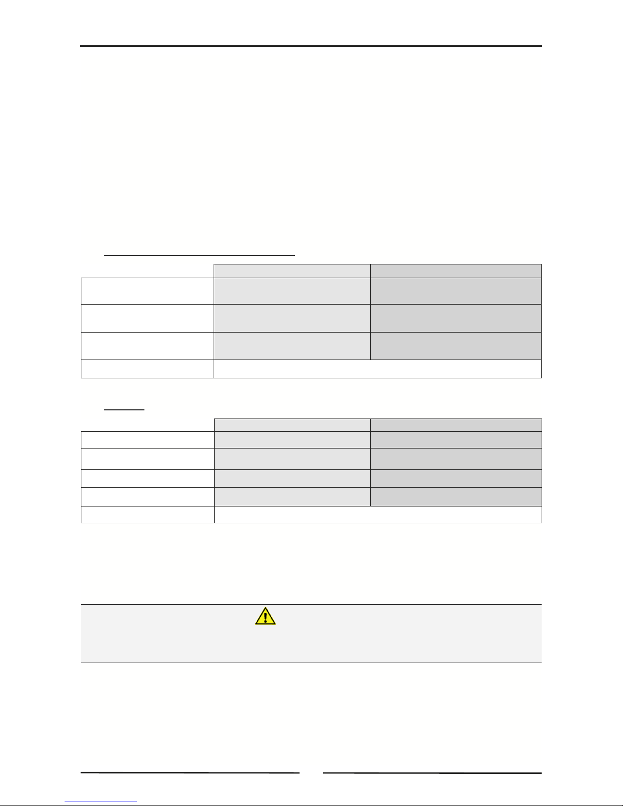
Natural Gas LP Gas (Propane)
Input Rating 90MJ/hr 90MJ/hr
(N.H.G.C.) (85,300Btu/hr)
(85,300Btu/hr)
Supply Pressure
1.13 - 2.00kPa 2.75 - 3.00kPa
(4.5” - 8.0” w.c.) (11” - 12” w.c.)
0.98kPa 2.50kPa
(3.9” w.c.) (10.0” w.c.)
Gas Connection ¾” BSP Male
Operating Pressure
Natural Gas (G20) Propane (G31)
Heat Input (nett) 22.5kW 22.5kW
Gas Rate 1.75kg/hr
Supply Pressure 20mbar 37mbar
Burner Operating Pressure 9.8mbar 25mbar
Gas Connection
3
/4” BSP Male
2.26m3/hr
THIS APPLIANCE MUST BE EARTHED. IF SUPPLY CORD IS DAMAGED, IT MUST BE REPLACED BY A SUITABLY
QUALIFIED PERSON IN ORDER TO AVOID A HAZARD.
Warning
5
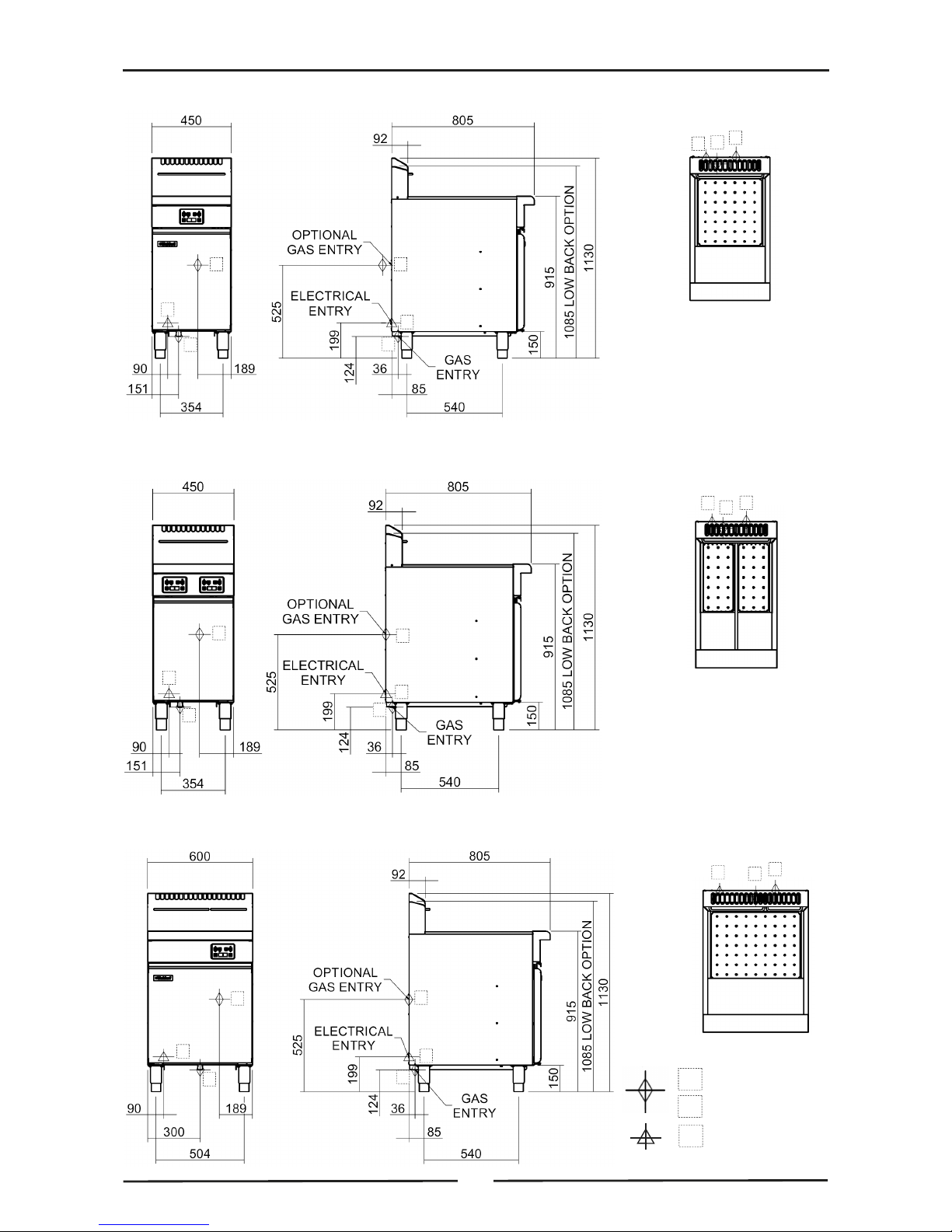
Dimensions
FN
(L)
8130GE
3
3
2
1
2
1
3
2
1
FN
(L)
8226GE
3
2
1
3
3
2
1
2
1
FN
(L)
8120GE
3
2
1
3
3
2
1
2
1
1. Primary Gas Entry Point.
2. Optional Gas Entry Point.
3. Electrical Entry Point.

6
Installation
Installation Requirements
NOTE:
It is most important that this Fryer is installed correctly and that the operation is
correct before use. Installation shall comply with local electrical, gas and health and
safety requirements.
This appliance shall be installed with sufficient ventilation to prevent occurrence of
unacceptable concentrations of health harmful substances in the room, appliance is
installed in.
Waldorf ‘FAST FRI’ gas fryers are designed to provide years of satisfactory service, and correct installation
is essential to achieve the best performance, efficiency and trouble-free operation.
This appliance must be installed in accordance with National installation codes and in addition, in
accordance with relevant National / Local codes covering gas and fire safety.
Australia / New Zealand AS 5601.1 - Gas Installations.
Australia / New Zealand: AS / NZS 3000 - Wiring Rules.
United Kingdom: Gas Safety (Installation and Use) Regulations 1998.
United Kingdom: BS 7671 - Requirements for Electrical Installations.
Ireland: IS 820 - Non Domestic Gas Installations.
Installations must be carried out by qualified service persons only. Failure to install
equipment to the relevant codes and manufacturer’s specifications shown in this section will
void the warranty.
Components having adjustments protected (e.g. paint sealed) by manufacturer are only to be
adjusted by an authorised service agent. They are not to be adjusted by the installation
person.
Unpacking
Remove all packaging and transit protection from appliance including all protective plastic coating
from door outer panel and exterior stainless steel panels.
Check equipment and parts for damage. Report any damage immediately to carrier and distributor.
Report any deficiencies to distributor who supplied appliance.
Check available gas supply is correct to as shown on rating plate located on inside of door.
Check the following parts have been supplied with the appliance:-
FN8120GE FN8226GE FN8130GE
Baskets 2 2 3
Basket Grids 1 2 1
Lid 1 1 1
Adjustable Legs 4 4 4
Drain Stick 1 1 1
Rear Rollers 2 2 2 (NZ only, Rollers fitted).
Location
1. This appliance must be installed in a suitably ventilated room to prevent dangerous build up of
combustion products.
2. Installation must allow for a sufficient flow of fresh air for combustion air supply. Combustion air
requirements:
Combustion Air Requirements
All Gas Types 24 m³/hr minimum.
3. Position the appliance in its approximate working position.
4. All air for burner combustion is supplied from beneath appliance. Legs must always be fitted and no
obstructions placed beneath or around base of appliance, as obstructions will cause incorrect
operation and / or failure of appliance.
NOTE: Do not obstruct or block appliance flue. Never directly connect a ventilation system to
appliance flue outlet.

7
Installation
Clearances
NOTE:
Only non-combustible materials can be used in close proximity to this appliance.
To facilitate easy operation, drainage and servicing of appliance, a minimum of
600mm clearance should be maintained at front of appliance.
Any gas burning appliance requires adequate clearance and ventilation for optimum and trouble-free
operation. The following minimum installation clearances are to be adhered to:
Assembly
This model is delivered completely assembled. Ensure that the legs are securely attached.
NOTE:
This appliance is fitted with adjustable feet to enable it to be positioned securely and
level on uneven floors. This should be carried out on completion of gas connection.
Refer to 'Gas Connection Section'.
The rear leg housings on this appliance can also be fitted with rear rollers to enable
the appliance to be easily moved for positioning and cleaning purposes. If desired,
these rollers are supplied in the packaging, with appliance. See overleaf for fitting
instructions.
Optional Accessories (Refer to Replacement Parts List)
Plinth Kit. For installation details, refer to the instructions supplied with each kit.
Combustible Surface Non Combustible Surface
Left / Right Hand Side 50mm. 0mm.
Rear 50mm. 0mm.
8
Installation
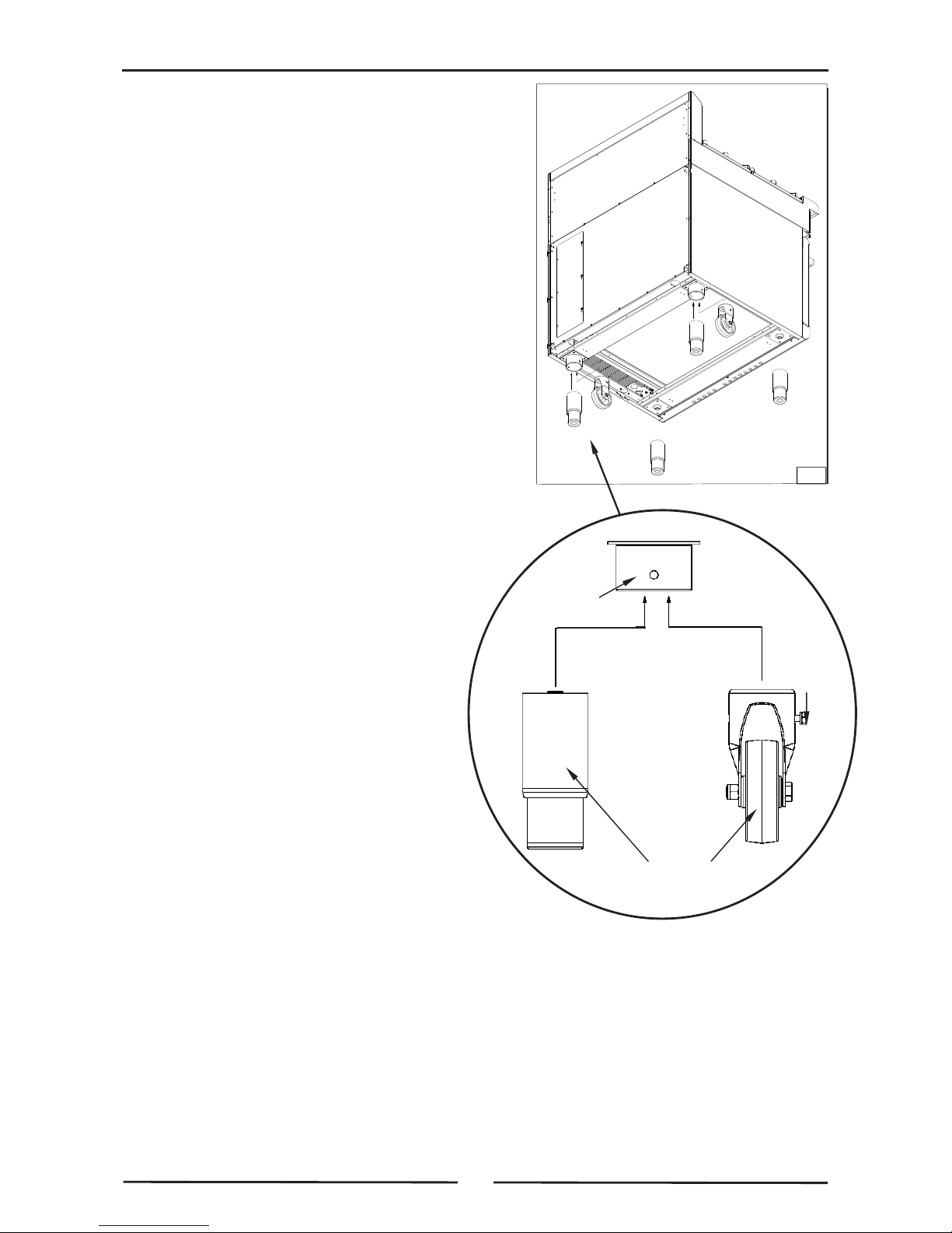
Fitting Rear Rollers.
1. Raise the appliance from the floor by approx. 75mm
using suitable lifting equipment (i.e. Palletiser /
Forklift) to allow rear adjustable feet to be removed.
2. Unscrew and remove both rear adjustable feet from
rear leg housings.
3. Fit rear roller to rear leg housing and align screw
hole in side of rear leg housing with threaded hole in
rear roller.
4. Secure the rear roller to the leg support with bolt
supplied and tighten bolt.
5. Fit second roller and tighten securing bolt.
6. Lower appliance back to the floor and adjust front
adjustable feet to level appliance.
Appliance
Base
Adjustable
Foot
Rear
Roller
Rear Leg
Housing
Roller
Locating Bolt
Fig 1
9
Installation
Electrical Connection
NOTE: ALL ELECTRICAL CONNECTION MUST ONLY BE CARRIED OUT BY A QUALIFIED PERSON.
1. Each appliance should be connected to an adequately protected power supply and an isolation
switch mounted adjacent to, but not behind the appliance. This switch must be clearly marked and
readily accessible in case of fire.
2. Check electricity supply is correct as shown on Rating Plate attached to inside of access door.
3. For immediate electrical supply, simply plug the lead into a properly earthed, 3 pin socket.
Gas Connection
NOTE: ALL GAS FITTING MUST ONLY BE CARRIED OUT BY AN AUTHORISED PERSON.
Flexible Hose Connection.
If a Gas Hose assembly is used to connect this appliance, hose and all fittings must have a minimum
¾” (Natural Gas) or ½” (LPG) inside bore diameter to ensure gas flow rate capacity required by this
appliance is achieved.
This must be verified by operating pressure testing at maximum gas supply demand condition.
Gas Hose assembly should also be classified for use in commercial kitchen conditions that appliance
will be used in.
Recommended Gas Hose Assembly Specification:
- AS/NZS 1869 Class B or D compliant or equivalent, that meets the following requirements:-
NOTE: ALL GAS FITTING MUST ONLY BE CARRIED OUT BY A QUALIFIED SERVICE PERSON.
1. It is essential that the gas supply is correct for the appliance being installed and that adequate
supply pressure and volume are available. Carry out the following checks before installation:-
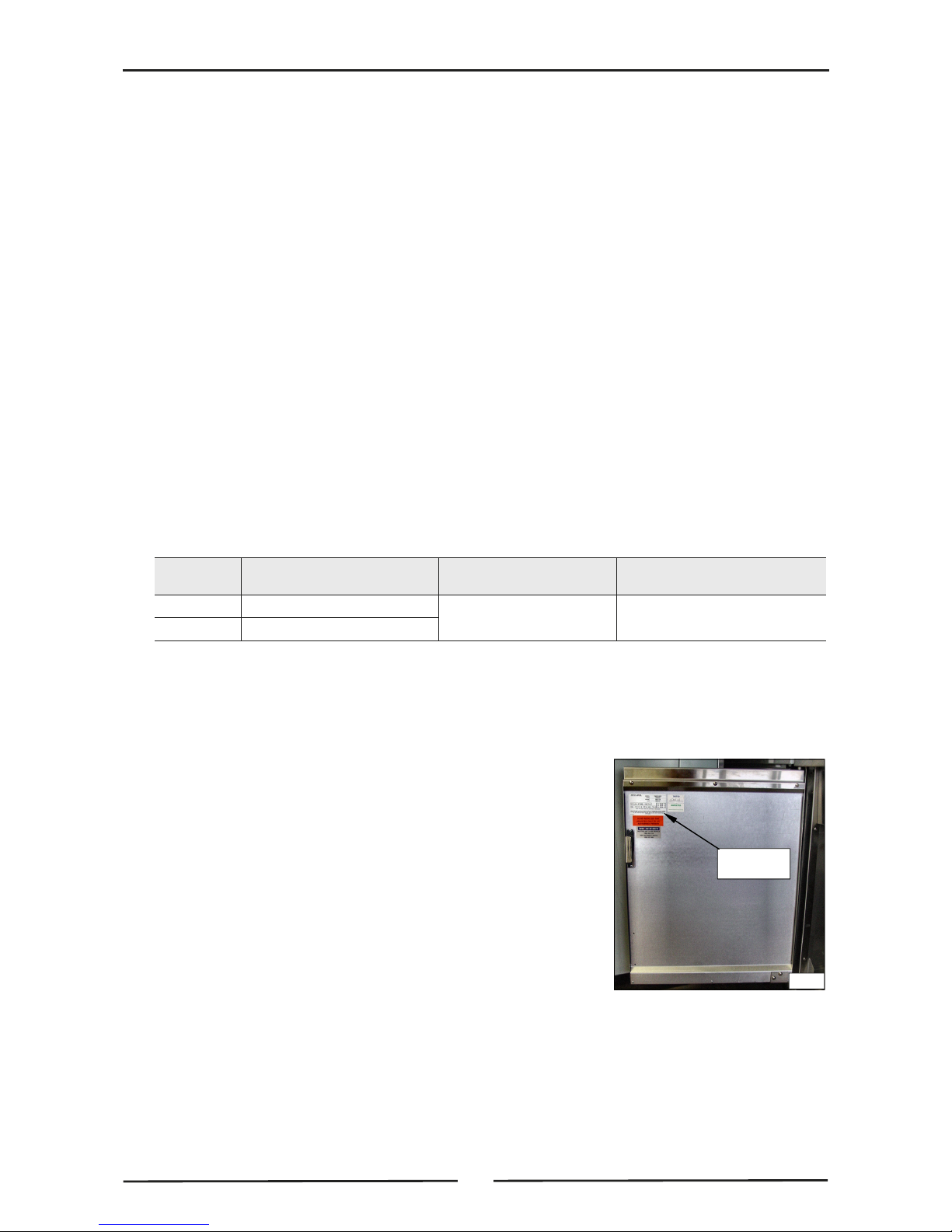
a. Gas Type appliance has been supplied for is shown on
coloured stickers located above gas entry point and next to
rating plate. Check that this is correct for gas supply
appliance is being installed for. Gas conversion procedure is
shown in this manual.
b. Supply Pressure required for this appliance is shown in
Specifications section of this manual. Check gas supply to
ensure that adequate supply pressure exists.
c. Input Rate of this appliance is also shown on Rating Plate
fitted to inside of access door and in Specifications section
of this manual. Input rate should be checked against
available gas supply line capacity. Particular note should
be taken if appliance is being added to an existing
installation.
NOTE: It is important that adequately sized piping runs directly to connection joint on appliance,
with as few tees and elbows as possible to give maximum supply volume.
Rating Plate
Location
Fig 2
Class
Max Working Pressure
at 23 ± 2ºC
Working Temperature
Range
Resistance to Oil
B 7.0 kPa
- 20ºC to + 125ºC
D 2.6 MPa
Oil resistant lining and cover.
10
Installation
2. A suitable joining compound which resists the breakdown action of LPG must be used on every gas
line connection, unless compression fittings are used.
Connection to appliance is
3
/4” BSP male.
NOTE: A Manual Isolation Valve must be fitted to individual appliance supply line.
3. Correctly locate appliance into its final operating position and using a spirit level, adjust legs so that
unit is level and at correct height.
4. Connect gas supply to appliance.
5. Check all gas connections for leakages using soapy water or other gas detecting equipment.
6. Check gas supply pressure is as shown in Specifications section, Gas Supply Requirements
table.
NOTE: Measure gas supply pressure at Upper Test Point (Supply Pressure) on the gas control
valve.
7. Light Pilot Burners. Refer to Operation section, Lighting Pilot Burners.
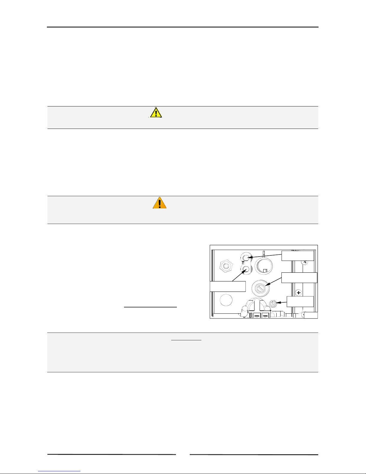
8. Check pilot flame size. Re-adjust if required, using pilot adjusting screw (See Fig 3 below), and as
shown in Gas Conversion and Specifications section, Pilot Burner Flame Adjustment.
9. Light the Main Burners. Refer to Operation section, Lighting Main Burners.
10. Verify Supply Pressure is still correct.
11. Check Main Burner operating pressure (Adjust, using
Operating Pressure Adjusting Screw on Gas Control
Valve, see Fig 3), and as shown in Gas Conversion
and Specifications section, Main Burner Operating
Pressure Adjustment.
NOTE: Insufficient gas supply line capacity, indicated by
operating pressure drop during maximum gas
supply demand, is NOT ACCEPTABLE and may
invalidate the manufacturers warranty for this
appliance.
Ensure the tank(s) is / are filled with either water or oil prior to starting Main
Burners otherwise the fryer tank(s) may be damaged.
Caution
IMPORTANT:
Control Panel ‘ON / OFF’ Key provides ‘ON / OFF’ control of Controller and Main Burner
heating cycles ONLY.
Gas Valve Control Knob is used to turn the Gas System ‘ON / OFF’ as well as providing Pilot
Ignition and Pilot Standby functions.
DO NOT USE A NAKED FLAME TO CHECK FOR GAS LEAKAGES.
Warning
Supply Pressure
Test Point
Operating Pressure
Test Point
Pilot Adjusting
Screw
Operating Pressure
Adjusting Screw
Fig 3
 Loading...