

Page 1
WALDORF DVCA1 USER MANUAL
Waldorf Music GmbH
2016-09-15
1
Page 2

Introduction
Development Team
Thank you for purchasing the dvca1 dual VCA Eurorack module.
Like any Waldorf product, the dvca1 has been developed and produced
using milk from happy cows. We hope you enjoy it as much as we do.
Reading this user manual, you will discover all the device features, learn
its basic use and benefits from tips & tricks we gathered during product
development.
Your Waldorf Team
Disclaimer
Waldorf Music GmbH is not liable for any erroneous information contained in
this manual. The contents of this manual may be updated at any time without
prior notice. We made every effort to ensure the information herein is accurate
and that the manual contains no contradictory information. Waldorf Music
GmbH extends no liabilities in regard to this manual other than those required
by local law. This manual or any portion of it may not be reproduced in any form
without the manufacturer’s written consent.
Waldorf Music GmbH, Lilienthal Strasse 7, D-53424 Remagen,
Germany
Development: Rolf W¨ohrmann, Frank Schneider
Design & Konzept: Stephan Gries, Axel Hartmann
Betatest: Dirk Krause, Falko Brocksieper
Manual: Dirk Krause, Oliver Rockstedt
Revision: 1.0, 2016-09-15
We would like to thank :
Joachim Flor, Willie Eckl, Michael von Garnier, Stefan Stenzel, Karsten
Dubsch, Daniel Krawietz, Kurt ”Lu” Wangard, Echo Wu, Miroslaw ”Mirek”
Pindus, Thomas Brenner, Fr´ed´eric Meslin, Victor H¨oller, Christian Bacaj,
Isabelle Kernhof, Roger Keller, Markus Erdmann, Holger Steinbrink, Juergen
Driessen, Christian Gritzner, Mic Irmer
For additional information / sound demos / software downloads, please visit our
website:
http://www.waldorf-music.info
2
Page 3
1 GENERAL SAFETY GUIDELINES CONTENTS
Contents
1 General Safety Guidelines 3
2 Device Maintenance 4
3 Package Contents 4
4 Controls & Connectors 5
5 Device Connection 6
5.1 Power Connection . . . . . . . . . . . . . . . . . . . . . . . . . . 6
5.2 Signal Connection . . . . . . . . . . . . . . . . . . . . . . . . . . 6
6 Device Overview 7
6.1 Inputs . . . . . . . . . . . . . . . . . . . . . . . . . . . . . . . . . 7
6.2 Outputs . . . . . . . . . . . . . . . . . . . . . . . . . . . . . . . . 7
6.3 Level Control . . . . . . . . . . . . . . . . . . . . . . . . . . . . . 7
6.4 Overall Gain . . . . . . . . . . . . . . . . . . . . . . . . . . . . . . 8
6.5 Filtering . . . . . . . . . . . . . . . . . . . . . . . . . . . . . . . . 8
6.6 Link Modes . . . . . . . . . . . . . . . . . . . . . . . . . . . . . . 9
7 Tips & Tricks 10
8 Troubleshooting 10
8.1 Modules Power Fail . . . . . . . . . . . . . . . . . . . . . . . . . 10
1 General Safety Guidelines
Please read the following safety guidelines carefully!
They include precautions you should always observe when dealing with electronic equipment.
• Use the device indoors only, in a dry atmosphere.
• Never use the device under too damp conditions such as in bathrooms or
near swimming pools.
• Do not use the device in extremely dusty or dirty environments in order to
preserve the device’s surface finish.
• Make sure that adequate ventilation is available for the device to cool
down. Do not place the device near heat sources such as radiators.
• Do not expose the device to extreme vibrations.
• Unplug the device when you are not using it for longer periods.
• Never place objects containing liquids on top or near the device.
• Make sure no foreign objects find their way into the unit. If this occurs,
switch the power off, unplug the device and consult a qualified repair center.
9 Specifications 10
10 Block Diagram 11
This device, used with amplifiers, speakers or headphones, can generate volume levels that may result in irreparable damage to human hearing. For this
reason, volume should be kept at moderate levels at all times.
This device is designed exclusively to generate low frequency audio signals
for sound generation. Any other use is prohibited and voids the warranty extended by Waldorf Music GmbH. Damages due to incorrect use are not the
responsability of Waldorf Music GmbH.
3
Page 4

2 Device Maintenance
• Do not try to open the device or detach the frontpanel.
• Refer all service and repair tasks to qualified personnel.
• There are no user serviceable parts inside the chassis.
• Use only a soft cloth or brush to clean the device surface.
• Never use cleaning chemicals as they will damage the device surface.
3 Package Contents
The dvca1 package contains the following parts:
• dvca1 Dual VCA Module
• 1 x 10-way 20cm ribbon cable
• 4 x M2.5 x 6 screws
• 4 x M3 washers
3 PACKAGE CONTENTS
Only a Phillips head screwdriver #0 is needed to mount the module into your
modular rack. No additional tools are needed.
4
Page 5
4 CONTROLS & CONNECTORS
4 Controls & Connectors
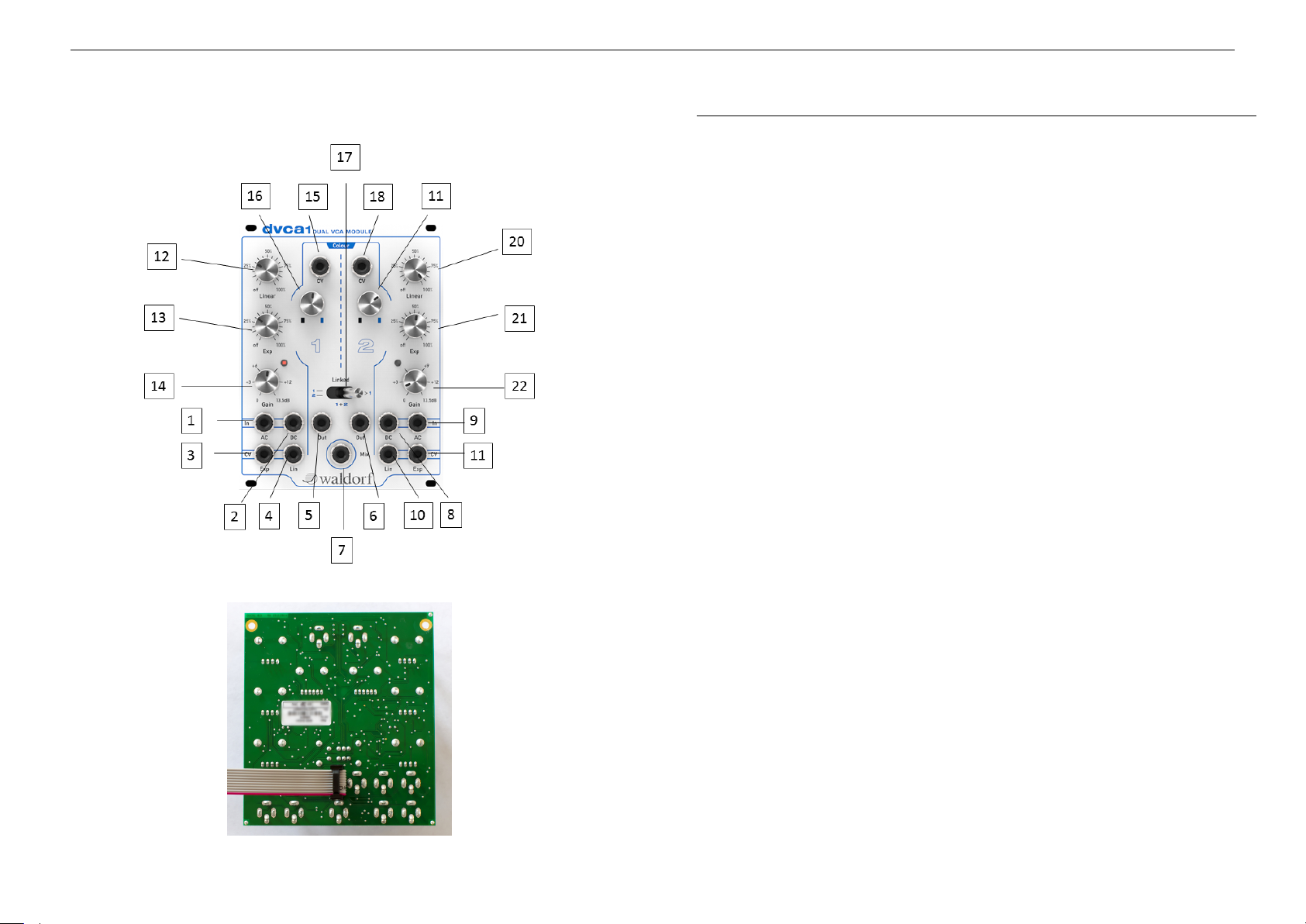
No Id Description
1, 9 AC input For your audio signals
2, 8 DC input Used for audio or control signals without the
filtering option (Colour)
3, 11 Exp CV input Used to modulate the Exponential parameter
4, 10 Lin CV input Used to modulate the Linear parameter
5, 6 Audio output Individual audio outputs
7 Mix output Provides the sum of both output signals
12, 20 Linear knob Controls the amount of VCA modulation
13, 21 Exponential knob Controls the amount of VCA modulation
14, 22 Gain knob Used for gain control (up to +13.5dB gain)
15, 18 Colour CV input Used for controlling the two-pole low-pass fil-
ter, called ”Colour”
16, 19 Colour attenuator knob Used for controlling the amount of ”colouring”
17 Linked switch Used for choosing from 3 different modes
5
Page 6
5 DEVICE CONNECTION
5 Device Connection
You now own a fantastic amplification module. It’s time to integrate it in your
modular system.
5.1 Power Connection
The first step is to supply your module with power. The module only requires
regulated +12V and -12V voltages. These voltages should already be provided
by your modular system’s power supply.
Before connecting any module to the Eurorack bus, it is mandatory to switch the
modular system power off. Otherwise you may severely damage your module
or put yourself at risk.
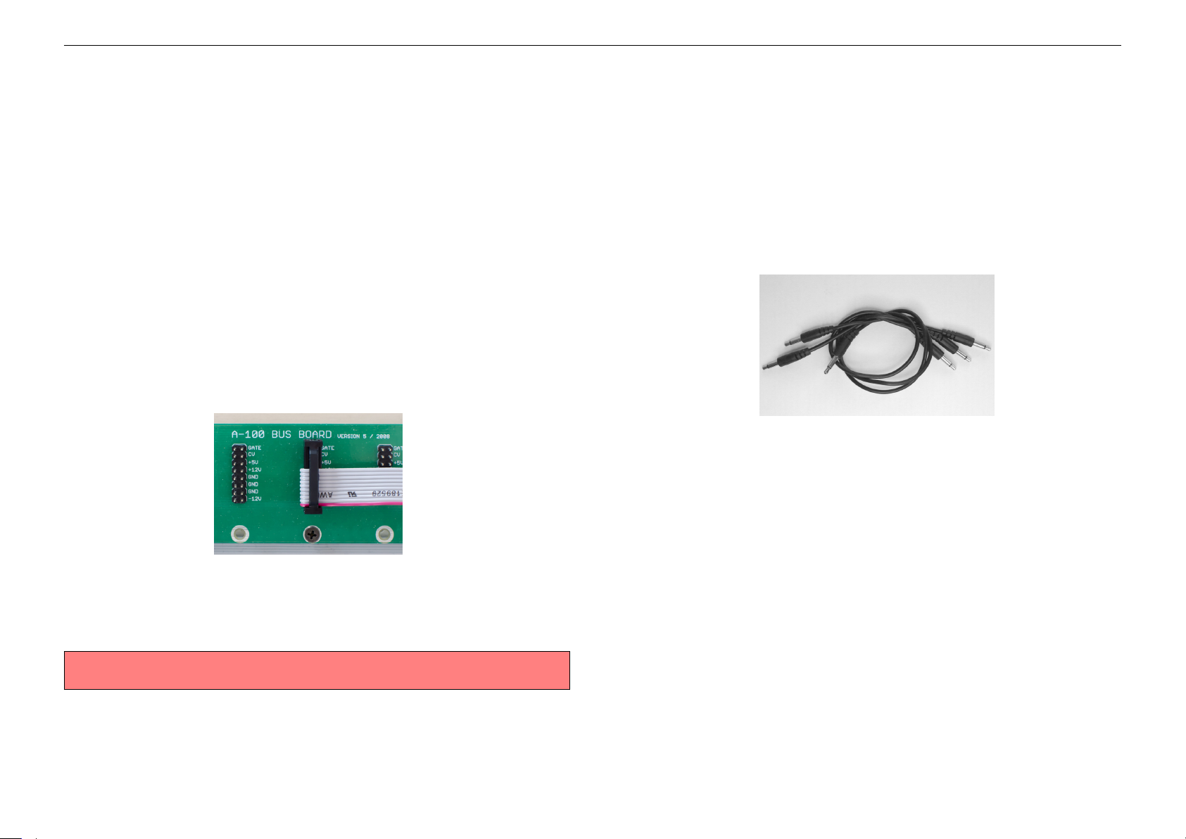
Please connect the supplied ribbon cable with the smaller 10-way connector to
the module’s Eurorack bus connector and with the larger 16-way connector to
your modular system bus board.
5.2 Signal Connection
The second step is to integrate the dvca1 to your Eurorack system.
Connect an audio signal like a VCO, sound source or any other audio signal to
one of the AC inputs and connect the Mix- or individual outputs to your studio
system. Now begin to modulate the VCA level, panning and/or the filter called
Colour for your pleasure.
Connections are made by using mini patch cables. These cables have standard
mono male-male mini plugs (3.5mm) and can be bought from any audio store.
Eurorack connectors are usually orientated in a way that the -12V supply line is
located at the bottom. The dvca1 module follows the same convention.
The red line of the ribbon cable should show to the bottom of your bus board
and at the bottom of your module. Refer to the figure above.
Please make sure the ribbon cable does not swap the lines.
The module can now be installed in the rack using the provided screws, washers
and a Phillips head screwdriver #0. With the module installed, switch the system
power supply on.
6
Page 7
6 DEVICE OVERVIEW
6 Device Overview
What is a VCA? VCA stands for Voltage Controlled Amplifier. Ok, and what is a
VCA good for? It’s a necessary module to amplify or attenuate audio or control
signals in your system. Not the fanciest type of module in the world of Eurorack
aficionados and not as exciting as a VCO, VCF or modulation module - until
now!
Waldorf creates a remarkable new tool to make amplification real fun and
satisfying. It’s a new level of innovation and possibilities. The new design of
the dvca1 supports your personal workflow in a fantastic way and gives you a
smart instrument to develop your sound further on.
Built around two analog VCAs with a wide range of options including the most
important one: the ability to musically colour the audio signal.
The Waldorf dvca1 comprises two identical VCAs which can be optionally
linked together for stereo control or panning effects. Each VCA could be either
fed by an audio signal via the AC input or control signal via the DC input.
For maximum flexibility, it offers linear and exponential control at the same time.
An additional overall gain control makes the dvca1 a true amplifier by adding
up to 13.5dB gain. This is an option not found in most VCAs.
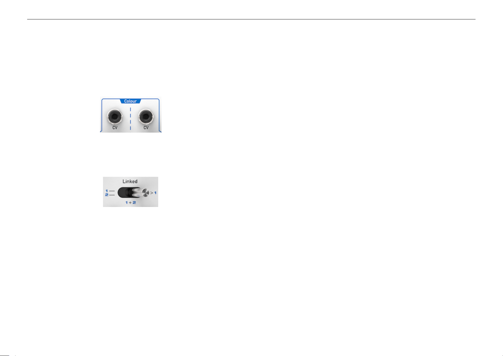
Via the Colour control a two-pole low-pass filter is added to give the sound an
extra timbre much like a traditional low-pass gate but with much quicker reaction
times and smooth filtering for impressive and sharp sounds.
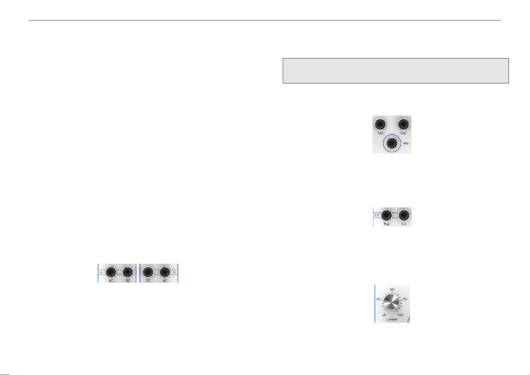
6.1 Inputs
Control signals like those from LFOs or envelope generators to be processed
by the VCA should always connected via the DC input.
Hint: It’s not intended to have both AC and DC inputs of the same VCA used
simultaneously, although it doesn’t harm in any way.
6.2 Outputs
Each VCA has its individual output regardless if the VCA has been fed via AC
or DC input. In addition the Mix output provides the sum of both output signals.
6.3 Level Control
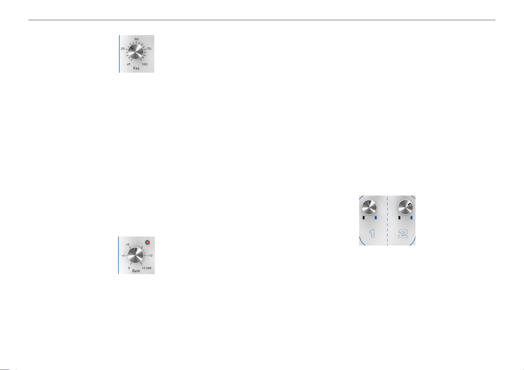
Each VCA has two control inputs: Linear and Exponential. Both could be used
simultaneously. In this case the amplification of both is simply added.
The linear control simply multiplies the amplitude of the input signal with the
amount of the control signal.
Audio signals should be fed into the AC input which provides a DC blocking
circuit. This is useful for example when connecting from external equipment.
Further, the AC input connects internally to the low-pass filter which is activated
by opening the Colour knob. Alternatively audio signals could also connected to
the DC input, but then lacking the mentioned filtering and DC blocking features.
The exponential control modifies the gain of the signal on a Decibel scale.
7
Page 8
6.4 Overall Gain 6 DEVICE OVERVIEW
In full open position the VCA delivers 13.5dB gain when the VCA is fully opened
(related to 5V CV input on either linear or linear inputs with respective knob
fully opened).
This overall gain simply scales the level of the VCA including any applied
modulation. Therefore this is different from classical ’initial gain’ configuration
Linear mode is often used when processing control signals while exponential
mode is used for audio signals modulated by linear controls like triangle LFOs
etc. However, when the modulating signal itself is non-linear like from classic
envelopes, using linear mode for modulating audio with these could be more
appropriate. Let your ears decide!
which adds a constant level to the signal.
The latter could be simply realised with the dvca1 by using one of the linear /
exponential control with the CV input and the other without which then would
add constant gain by opening the respective panel knob.
Exponential mode gives much more sharp modulations compared to linear
mode. And you could combine both of course for more complex and impressive
scenarios.
Both controls work this way: when the CV input isn’t used, the panel knob
opened fully would forward the signal unchanged in level. When fully closed
the signal is muted. When the CV input is used from a modulation source, the
panel knob is used to attenuate the control signal from unchanged when fully
opened to muted at fully left. Thus, inputting a 5V CV signal with fully opened
panel knob relates to an unchanged signal (assuming the overall gain knob is
closed).
6.4 Overall Gain
In addition to the linear and exponential level controls each VCA has an overall
gain knob.
When fully closed the VCA works in the traditional way giving no true amplification of the input signal. However, by opening the gain knob the VCA becomes
a true voltage controlled amplifier.
Depending on the level of the input signal, the overall level could result in hard
clipping distortion.
The red LED next to the Gain knob indicates that the input signal is closed to the
clipping level, resulting in distortion. This could of course be used intentionally
for shaping the sound.
6.5 Filtering
When using the AC input for audio, the signal is fed through a two-pole low-pass
filter before it reaches the VCA.
When the Colour knob is fully left, the filter is opened and the signal is fed
almost unchanged into the VCA. But turning the Colour knob clockwise, the
filter cutoff frequency is bound increasingly to the VCA linear and exponential
controls in the following way: The more the VCA is attenuating the signal, the
more the cutoff frequency of the low-pass filter is reduced.
This results in a timbre variation in parallel to level variation. The amount of this
parallel movement is increased by turning the Colour knob clockwise. You add
8
Page 9
6 DEVICE OVERVIEW 6.6 Link Modes
a warmer and more colourful timbre to the signal based on a finely-crafted OTA
filtering circuit.
This effect is similar to a classic low-pass gate. However, while the classic
low-pass gate is realised with a vactrol and therefore isn’t able to be modulated
quickly, the OTA-based low-pass filter in the dvca1 can be modulated at any
speed up to audio rate for giving a rich and flexible timbre control.
The amount of colour filtering can be also controlled via the CV input. In this
case the panel knob acts as an attenuator to the applied CV signal.
6.6 Link Modes
linear control, the right is closed and vice versa. The Exponential and
Gain controls of the right VCA (2) are not affected and could be used in
addition. This can be used for auto-panning effects e.g. when modulating
volume by an LFO.
The level control section of the right VCA could be linked to the left VCA.
They are three link modes: independent, parallel and anti-parallel.
• Independent mode for every channel in left position of the switch.
• In parallel mode (switch is in middle position) the linear and exponential
controls (i.e. panel knobs and its CV inputs) of the right VCA (2) are
disabled and instead the controls of the left VCA (1) are used. In this
configuration e.g. a stereo signal can be modulated by just using CV on
the left section (1). However, the gain knob of the right VCA (2) is still
active in order for overall level compensation or panning effects.
• In anti-parallel mode (switch is in right position) only the linear control
section of the right VCA (2) is disabled. Instead the linear control of the
left VCA (1) is used in reverse way: When the left VCA (1) is open by
9
Page 10

9 SPECIFICATIONS
7 Tips & Tricks
In addition to classical modulations like LFOs or envelopes, the CV inputs could
also be fed with audio signals. The resulting modulation can be very interesting
much like - but not strictly identical to - ring modulation.
A typical use for anti-parallel mode would be panning effects by feeding a LFO
signal into the left linear CV input.
Try to modulate the Colour parameter with a sample & hold or envelope signal
to come up with some fundamental groovy patches.
Also the possibility to modulate the Colour in stereo setups with different
amounts gives you some nice filter flavours.
8 Troubleshooting
8.1 Modules Power Fail
• Check the orientation of the pin headers on your modules
• Check if the total power consumption of your modules does not exceed
the specifications of your case/frame power supply
9 Specifications
Power Supply: +12V/100mA, -12V/100mA
Width: 20HP, 101.6mm
Height: 3U, 133.3mm
Depth: 25mm
Total Weight: 350g
Technical specifications and design are subject to change without notice.
10
Page 11
10 BLOCK DIAGRAM
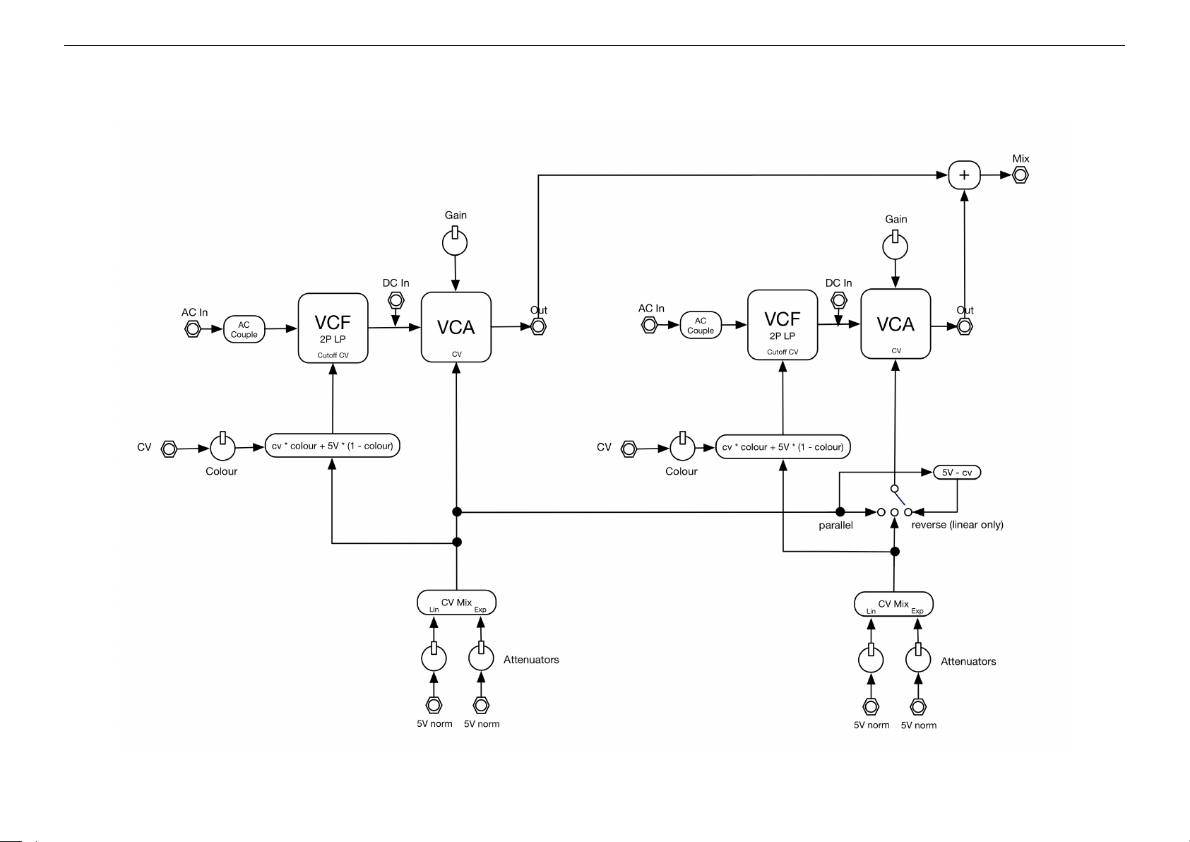
10 Block Diagram
11
 Loading...