

Walchem WDP420, WPH420, WPH410, WDP340, WDP410 Instruction Manual

W A L C H E M
W
PH/WDP Controllers
WPH/WDP Series
pH & ORP Controllers
Instruction Manual
Walchem Corporation Five Boynton Road Hopping Brook Park Holliston, MA 01746 USA
TEL: 508-429-1110 FAX: 508-429-7433 WEB: www.walchem.com

Notice
© 2008 WALCHEM Corporation
5 Boynton Road, Holliston, MA 01746 USA
(508) 429-1110
All Rights Reserved
Printed in USA
Proprietary Material
The information and descriptions contained herein are the property of WALCHEM Corporation. Such
information and descriptions may not be copied or reproduced by any means, or disseminated or
distributed without the express prior written permission of WALCHEM Corporation, 5 Boynton Road,
Holliston, MA 01746.
This document is for information purposes only and is subject to change without notice.
Statement of Limited Warranty
WALCHEM Corporation warrants equipment of its manufacture, and bearing its identification to be
free from defects in workmanship and material for a period of 24 months for electronics and 12 months
for mechanical parts and electrodes from date of delivery from the factory or authorized distributor
under normal use and service and otherwise when such equipment is used in accordance with
instructions furnished by WALCHEM Corporation and for the purposes disclosed in writing at the time
of purchase, if any. WALCHEM Corporation's liability under this warranty shall be limited to
replacement or repair, F.O.B. Holliston, MA U.S.A. of any defective equipment or part which, having
been returned to WALCHEM Corporation, transportation charges prepaid, has been inspected and
determined by WALCHEM Corporation to be defective. Replaceable elastomeric parts and glass
components are expendable and are not covered by any warranty.
THIS WARRANTY IS IN LIEU OF ANY OTHER WARRANTY, EITHER EXPRESS OR IMPLIED, AS
TO DESCRIPTION, QUALITY, MERCHANTABILITY, FITNESS FOR ANY PARTICULAR PURPOSE
OR USE, OR ANY OTHER MATTER.
180362.A
August 2008

TABLE OF CONTENTS
1.0 INTRODUCTION........................................................................................................................1
2.0 SPECIFICATIONS..................................................................................................................... 2
2.1 Measurement Performance...................................................................................................................2
2.2 Electrical: Input/Output ..........................................................................................................................2
2.3 Mechanical.............................................................................................................................................3
2.4 WPH/WDP Variables and their Limits....................................................................................................3
3.0 UNPACKING & INSTALLATION ..............................................................................................4
3.1 Unpacking the unit.................................................................................................................................4
3.2 Mounting the electronic enclosure.........................................................................................................4
3.3 Installation..............................................................................................................................................4
3.4 Icon Definitions ......................................................................................................................................5
3.5 Electrical installation ..............................................................................................................................7
4.0 FUNCTION OVERVIEW.......................................................................................................... 18
4.1 Front Panel ..........................................................................................................................................18
4.2 Display.................................................................................................................................................18
4.3 Keypad.................................................................................................................................................19
4.4 Access Code........................................................................................................................................19
4.5 Startup .................................................................................................................................................19
4.6 Shut Down ...........................................................................................................................................20
5.0 OPERATION............................................................................................................................20
5.1 Main Menu...........................................................................................................................................20
5.2 Sensor Menu........................................................................................................................................22
5.3 Temperature Menu (this menu does not appear if an ORP sensor has been selected).....................28
5.4 Control 1 - 4 Menus (FOR ON/OFF CONTROLLERS) .......................................................................29
5.5 Control 1-4 Menu (FOR PROPORTIONAL CONTROLLERS)............................................................34
5.6 Interlock A Menu..................................................................................................................................36
5.7 4-20 mA 1 and 2 Menus (Optional)......................................................................................................37
5.8 Time Menu...........................................................................................................................................38
5.9 Access Code Menu..............................................................................................................................39
5.10 Datalog Menu.......................................................................................................................................40
5.11 Config Menu.........................................................................................................................................42
5.12 Upgrade Menu.....................................................................................................................................44
6.0 MAINTENANCE.......................................................................................................................45
6.1 Electrode Maintenance........................................................................................................................45
6.2 Replacing the Fuses............................................................................................................................46
7.0 TROUBLESHOOTING............................................................................................................. 46
7.1 Error Messages....................................................................................................................................46
8.0 SERVICE POLICY...................................................................................................................48

1.0 INTRODUCTION
The Walchem WPH Series single sensor input and WDP Series dual sensor input controllers are wall
mount pH/ORP controllers that are available in on/off or modulated pulse proportional versions. They
are available with four on/off control relays (WPH410 or WDP410) with two modulated pulse
proportional output and two dry contact relays (WPH420 or WDP420) or four modulated pulse
proportional outputs (WDP340). A fifth output is used as a diagnostic alarm. One or two isolated 4-20
mA outputs are optional.
They are compatible with any amplified electrode. The choice of pH or ORP operation is selected
through the keypad. Use of Antimony pH electrodes is acceptable. Automatic temperature
compensation may be used via a Pt1000 or Pt100 input if pH operation is selected. The controller will
prompt you to calibrate the electrode at the desired frequency. Automatic buffer recognition may be
used in the calibration routine.
Our unique USB feature provides the ability to upgrade the software in the controller to the latest
version.
An advanced USB capability option is available. The Configuration file feature allows you to save all
the set points from a controller onto a USB flash disk, and then import them into another controller,
making the programming of multiple controllers fast and easy. The data logging feature allows you to
save the last 2 month’s readings and events to a USB flash disk.
1

2.0 SPECIFICATIONS
2.1 Measurement Performance
pH Range -2 to 16 pH units
pH Resolution 0.0015 pH units (0.01 pH displayed)
pH Accuracy (Calibrated): ± .01 pH
ORP Range -1500 to 1500 mV
ORP Resolution 92 µV (1mV displayed)
ORP Accuracy ±1 mV
Temp Comp (optional): 100 or 1000 ohm platinum RTD
Temperature Range 32-212°F (0-100°C)
Temperature Resolution ±0.09°F (0.05°C)
Temperature Accuracy ± 0.9°F (± 0.5°C)
2.2 Electrical: Input/Output
Input Power
Input Signals
pH/ORP ±1500 mV
Temp Comp (optional) Pt100 or Pt1000
Interlock (optional) Isolated, dry contact closure required (i.e., flow, level, etc.)
Outputs
Powered Relays Internally powered relays switching line voltage
Pulse Outputs Opto-isolated, Solid State Relay
Dry contact relays 6 A (resistive), 1/8 HP
Dry contact relays are not fuse protected
100-240 VAC, 50/60 Hz, 8A
Fuse: 1.0 ampere, 5 x 20 mm
6 A (resistive), 1/8 HP
All relays are fused together as one group, total current for this
group must not exceed 6A
150mA, 40 VDC Max.
VLOWMAX = .13V @ 18 mA
CTRL 1 CTRL2 CTRL 3 CTRL 4 ALARM
WPH410 Powered Powered Dry Dry Dry
WPH420 Pulse Pulse Dry Dry Dry
WDP410 Powered Powered Powered Powered Powered
WDP420 Pulse Pulse Dry Dry Dry
WDP440 Pulse Pulse Pulse Pulse Dry
Note: The Alarm relay is non-programmable. Refer to the Main Menu diagram for the list of error
conditions that trigger the alarm relay.
4 - 20 mA 1 or 2 (optional) Internally powered
pH/ORP Preamp Power ±5 VDC, 5 mA
Agency Approvals
CAN/CSA C22,2 No.61010-1:2004 2
CE Safety EN 61010-1 2
CE EMC EN 61326 :1998 Annex A*
Note: For EN61000-4-6,-3 the controller met performance criteria B.
*Class A equipment: Equipment suitable for use in establishments other than domestic, and those directly
connected to a low voltage (100-240 VAC) power supply network which supplies buildings used for
domestic purposes.
Fully isolated
600 Ohm max resistive load
Resolution .001% of span
Accuracy ± 1% of reading
UL ANSI/UL 61010-1:2004, 2
nd
Edition (2001)*
nd
Edition*
nd
Edition*
2

2.3 Mechanical
Enclosure Material Polycarbonate
NEMA Rating NEMA 4X
Dimensions 8.5" x 6.5" x 5.5"
Display 2 x 16 character backlit liquid crystal
Operating Ambient Temp 32 – 122°F (0 – 50°C)
Storage Temperature -20 – 180°F (-29 – 80°C)
Flow switch manifold temperature rating 140°F (60°C) max
Flow switch manifold pressure rating 150 psi
Flow switch manifold connections ¾" NPTF
2.4 WPH/WDP Variables and their Limits
Low Limit High Limit
Sensor menu
Temperature Menu
Control 1 -4 Menus
High or Low Set Point -2 pH, -1500 mV 16 pH, 1500 mV
High or Low Alarm Point -2 pH, -1500 mV 16 pH, 1500 mV
Dead Band (Relay Outputs only) 0 pH, 0 mV 1.99 pH, 199 mV
Proportional Band 0 pH, 0 mV 6.99 pH, 999 mV
Minimum SPM Rate (Pulse Outputs only) 0 strokes/minute 360 strokes/min
Maximum SPM Rate (Pulse Outputs only) 0 strokes/minute 360 strokes/min
Sample Period (Relay Outputs only) 0:01 min:sec 30:00 min:sec
Time Limit (Relay Outputs only) 0:01 min:sec 59:59 min:sec (enabled)
Hold Time (Probe Wash) 0 seconds 99 seconds
On Time (Probe Wash) 1 second 99 seconds
4-20 mA 1 and 2 Menus 4 & 20 mA Settings -2 pH, -1500 mV 16 pH, 1500 mV
Access Code Menu New Value 0 9999
Datalog Menu (Optional)
Config Menu (Optional)
Upgrade Menu
*Note: The Alarm relay is non-programmable. Refer to the Main Menu diagram for the list of error conditions
that trigger the alarm relay.
Days Between Calibration 0 days (no reminder) 59 days
No variables
0=unlimited (disabled)
No variables
No variables
No variables
3

3.0 UNPACKING & INSTALLATION
3.1 Unpacking the unit
Inspect the contents of the carton. Please notify the carrier immediately if there are any signs of damage
to the controller or its parts. Contact your distributor if any of the parts are missing. The carton should
contain: a WPH/WDP series controller and instruction manual. Any options or accessories will be
incorporated as ordered.
3.2 Mounting the electronic enclosure
The WPH/WDP series controller is supplied with mounting holes on the enclosure. It should be wall
mounted with the display at eye level, on a vibration-free surface, utilizing all four mounting holes for
maximum stability. Use M6 (1/4" diameter) fasteners that are appropriate for the substrate material of
the wall. The enclosure is NEMA 4X rated. The maximum operating ambient temperature is 122°F
(50°C); this should be considered if installation is in a high temperature location. The enclosure requires
the following clearances:
Top: 2" (50 mm)
Left: 8" (203 mm)
Right: 4" (102 mm)
Bottom: 7" (178 mm)
3.3 Installation
Once the enclosure is mounted, the metering pumps or other control devices may be located at any
distance from the controller. The electrode, once amplified, may be placed up to 1000 feet from the
controller. Shielded cable with twisted pairs is required. Always route AC voltage wiring in conduit that
is separated by 6 inches from low voltage DC signal lines (such as the electrode signal).
Electrode Installation
The WPH/WDP controllers are designed to work with most AMPLIFIED pH, ORP or ISE electrodes.
When in doubt, follow the electrode manufacturer's instructions for installation.
If you have ordered your controller with an external preamplifier pre-wired to the controller, simply
attach the electrode to the BNC connector on the preamplifier. If you are using automatic temperature
compensation, wire the ATC element to the preamplifier as shown in figure 3.
If you have ordered the external preamplifier separately, see figure 3 for wiring instructions.
NOTE: The cable between the electrode and the preamplifier is carrying an extremely sensitive high
impedance voltage signal. Never cut, splice or otherwise destroy the integrity of the cable or unstable
readings and susceptibility to electrical noise will result.
Instructions for physically mounting the electrode into the process solution will vary greatly with the
type of electrode and circumstances involved in your application. Here are some general guidelines to
assist you. Refer to figure 1, Typical Installation.
The electrode should be installed such that the measuring surfaces will always stay wet. Many
electrodes have to be installed vertically, with the measuring surfaces pointing down. Follow the
manufacturer's recommendations if this is the case. If the electrode dries out, a slow response and short
life will result.
4
For submersion applications, mount the electrode below the minimum solution level. If the tank will be
completely emptied, plan on removing the electrode and storing it in tap water (NOT DI water) or pH 4
buffer solution while the tank is empty. If this is not desirable, a recirculation loop may be installed
with the electrode mounted in-line. The WEL electrode cable is not waterproof and must be protected
from moisture by connecting a pipe to the top of the electrode housing. The opposite end of the pipe
should also be protected from moisture using a cable gland. When submerging the electrode, make sure
the cable is protected by a length of pipe, sealed at the top using a cable gland.
For in-line applications, where the electrode is installed in a pipe, the electrode should be placed on the
discharge side of the pump (under positive pressure). A "U" trap should be included so that if flow
stops, the electrode is still immersed in the solution. If the flow through the pipe can not be shut down
for cleaning and calibrating the electrode, install the electrode in a by-pass line with isolation valves to
allow for electrode removal. The electrode should be installed in an area where there is good solution
movement and where it will respond rapidly to chemical additions. The placement of the electrode
relative to the placement of chemical replenishment, along with the quality of the mixing and
replenishment flow rate, is critical to accurate control.
IMPORTANT: To avoid cracking the female pipe threads on the supplied plumbing parts, use no more
than 3 wraps of Teflon tape and thread in the pipe FINGER tight plus 1/2 turn! Do not use pipe dope to
seal the threads of the flow switch because the clear plastic will crack!
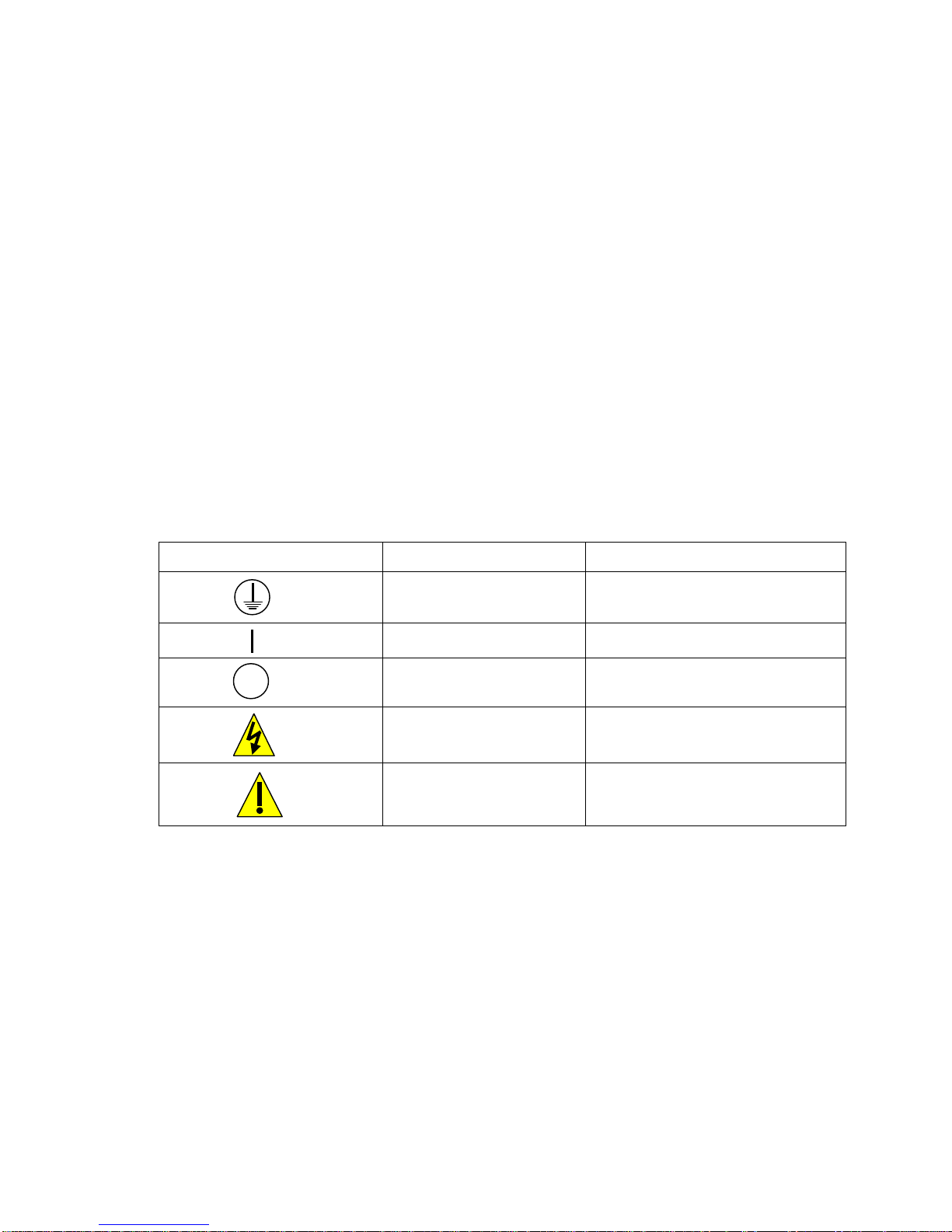
3.4 Icon Definitions
Symbol Publication Description
IEC 417, No.5019 Protective Conductor Terminal
IEC 417, No. 5007 On (Supply)
IEC 417, No. 5008 Off (Supply)
ISO 3864, No. B.3.6 Caution, risk of electric shock
ISO 3864, No. B.3.1 Caution
5
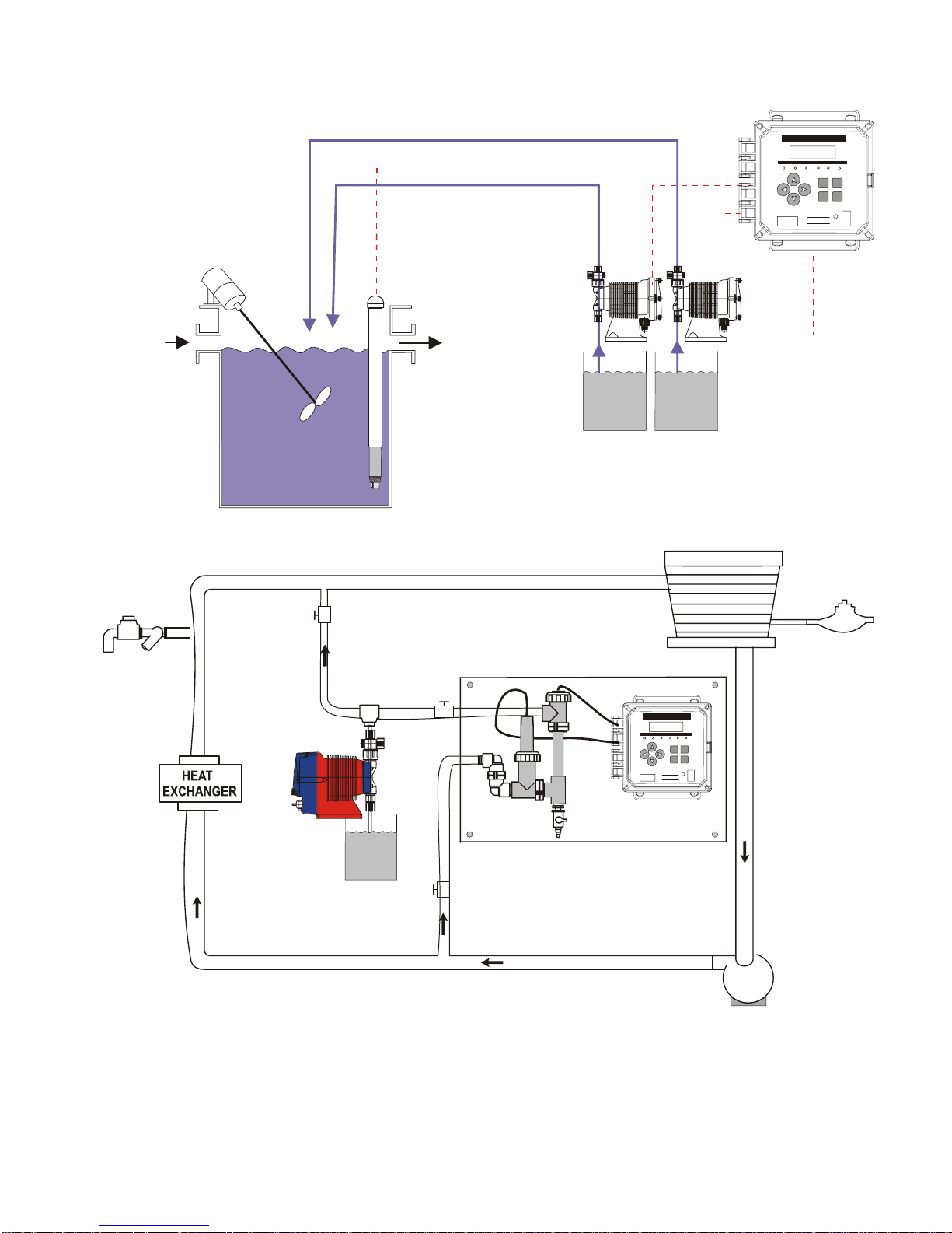
pH/ORP Controller
W A L C H E M
SOLENOID
VALVE
SUBMERSION
ELECTRODE
pH
PROBE
FLOW OUTFLOW IN
ACID
BASE
AC POWER
COOLING TOWER
WATER
METER
Flow
switch
Flow Switch
pH/ORP Controller
W A L C H E M
Installation with In-line electrode
pH
pH
Electrode
Electrode
Figure 1 Typical Installation
6
CIRCULATING
PUMP
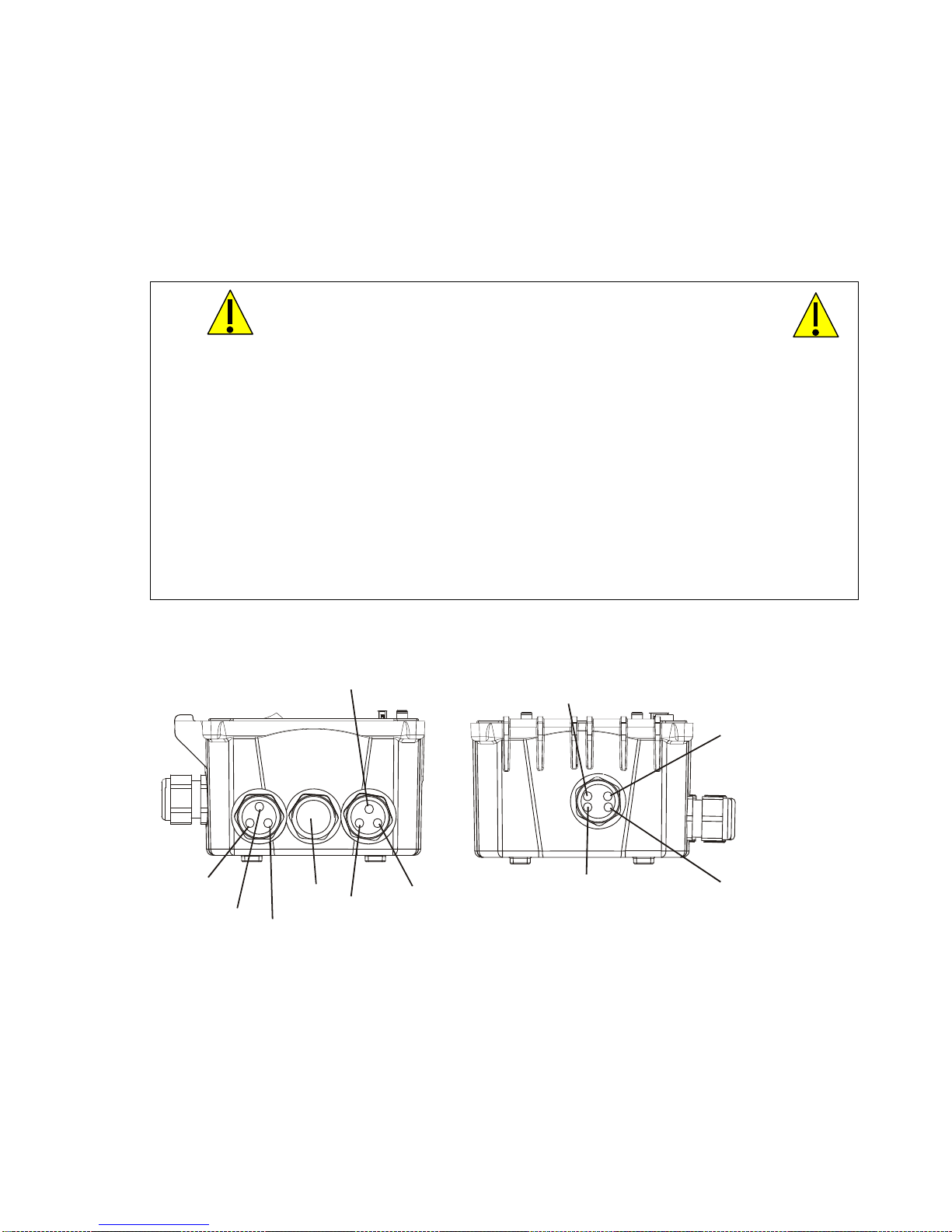
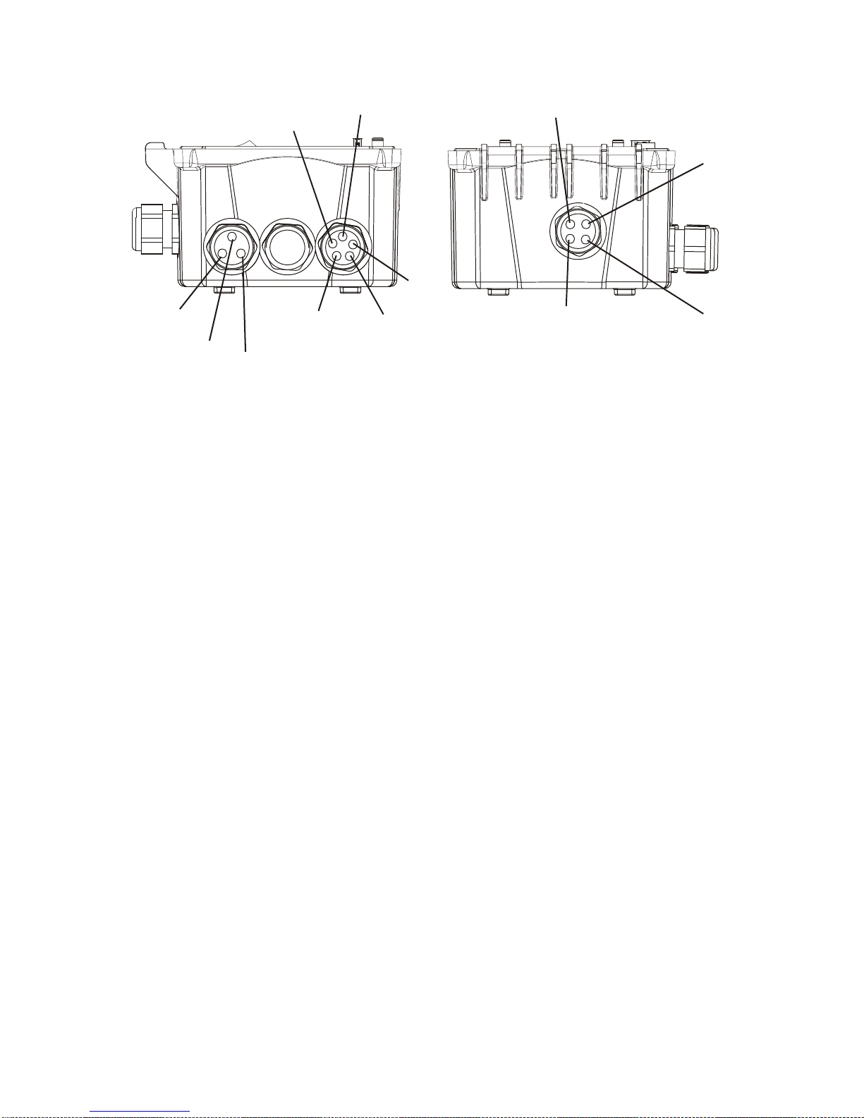
3.5 Electrical installation
C
)
The various standard wiring options are shown in figure 2. Your WPH series controller will arrive from
the factory prewired or ready for hardwiring. Depending on your configuration of controller options,
you may be required to hardwire some or all of the input/output devices. Refer to figures 3 and 4 for
circuit board layout and wiring.
Note: when wiring the optional 4-20 mA output or a remote interlock switch, it is advisable to use
stranded, twisted, shield pair wire between 22-26 AWG. Shield should be terminated at the controller
ground stud (see figures 3 and 4).
1. There are live circuits inside the controller even when the power switch on the front panel is in
the OFF position! The front panel must never be opened before power to the controller is
REMOVED!
If your controller is prewired, it is supplied with a 8 foot, 18 AWG power cord with USA
style plug. A tool (#1 Phillips driver) is required to open the front panel.
2. When mounting the controller, make sure there is clear access to the disconnecting device!
3. The electrical installation of the controller must be done by trained personnel only and
conform to all applicable National, State and Local codes!
4. Proper grounding of this product is required. Any attempt to bypass the grounding will
compromise the safety of persons and property.
5. Operating this product in a manner not specified by Walchem may impair the protection
provided by the equipment.
CAUTION
POWER
CTRL 1
TRL 2
ALARM
PLUG
CTRL 3
CTRL 4
Figure 2a WPH410 Conduit Wiring
4-20mA #2
(OPTIONAL)
pH/ORP
SENSOR
4-20mA #1
(OPTIONAL
FLOW SWITCH
(OPTIONAL)
7
1
1
4-20mA #1
(OPTIONAL)
4-20mA #2
(OPTIONAL)
pH/ORP
SENSOR
POWER
CTRL 3
CTRL 4
PLUG
CTRL 2
CTRL 1
ALARM
FLOW SWITCH
(OPTIONAL)
Figure 2b WPH420 Conduit Wiring
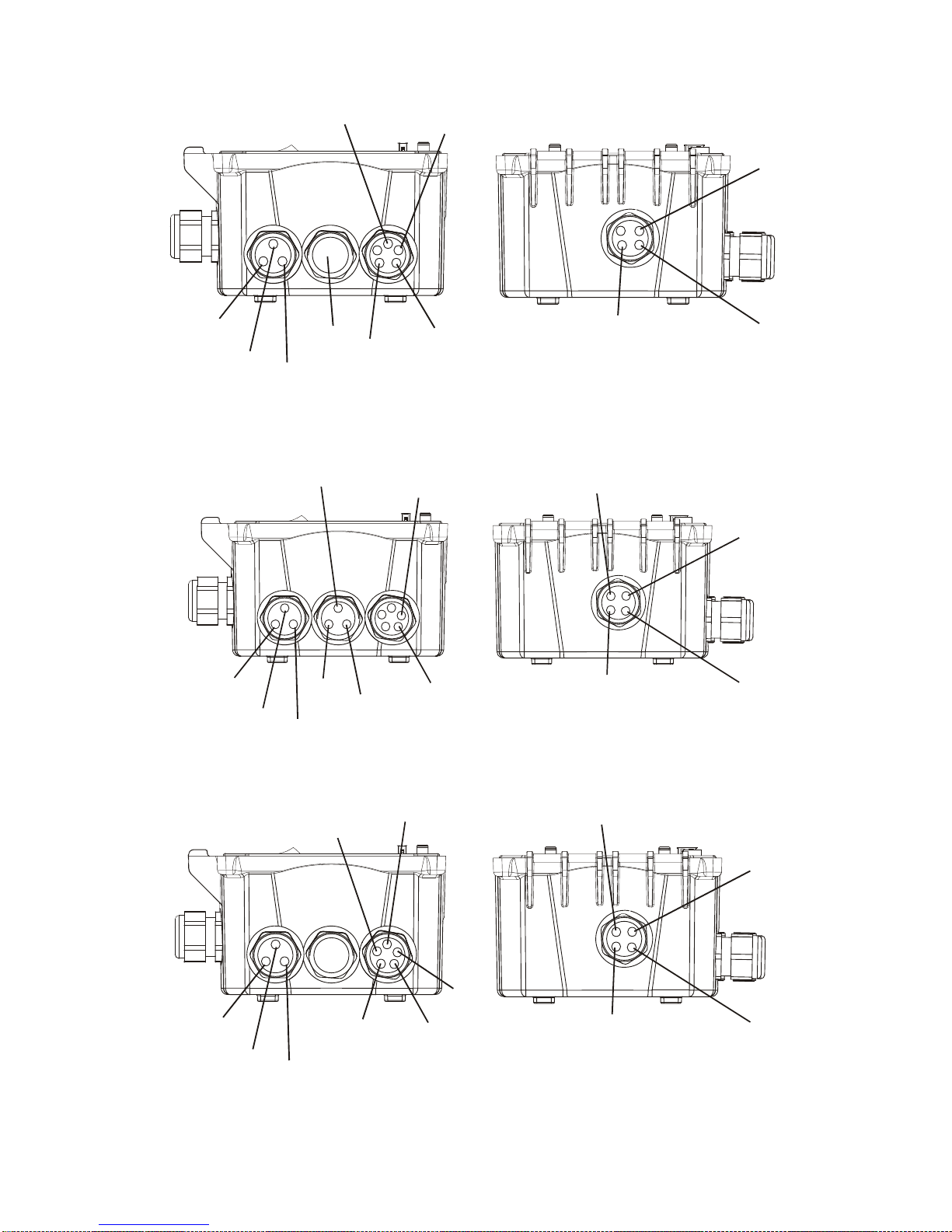
CTRL 4
4-20mA 1
FLOW SWITCH 2
pH/ORP
POWER
POWER
CTRL 3
CTRL 1
CTRL 2
CTRL 4
CTRL 3
ALARM
PLUG
FLOW
ALARM
4-20mA 2
SWITCH 1
Figure 2c WDP410 Conduit Wiring
FLOW SWITCH 2
FLOW
SWITCH 1
CTRL 2
4-20mA 1
4-20mA 2
CTRL 1
Figure 2d WDP420 Conduit Wiring
pH/ORP 2
pH/ORP
pH/ORP 2
8
POWER
ALARM
PLUG
CTRL 2
4-20mA 1
CTRL 1
4-20mA 2
FLOW SWITCH 2
pH/ORP 1
FLOW
SWITCH 1
pH/ORP 2
CTRL 3
CTRL 4
Figure 2e WDP440 Conduit Wiring
9
DIG IN 1
IN-
IN+
DIG IN 2
IN-
IN+
DIG IN 3
IN+ IN-
IN+
DIG IN 1
IN-
DIG IN 2
IN+
ININ+ IN-
DIG IN 3
IN+ IN-
DIG IN 4
IN+ IN -
DIG IN 5
DIG IN 4
IN+ IN-
IN+ IN-
+5V
-5V
DIG IN 5
IN+ IN-
T-T+
G
R
E
E
N
W
H
I
T
E
/
GROUND
STUD
O
R
N
G
R
N
L2 L2 L2 L2 L2 L2
+5V
W
B
H
L
I
U
T
E
/
O
R
N
E
/
B
L
U
FEED
N.O.N.C.
L2/N
BOI 1
N.C.
N.O. N.C. N.O.
WHT 120V
BLU 240V
BIO 2
ALARM
N.O.
N.O.
N.C.
BLEED
N.O. N.C.
N.C.
L1 L2/N
G
R
G
N
R
N
1
2
/
Y
0
E
V
L
2
4
0
V
-5VIN+ IN-
W
H
I
T
L1
B
B
L
R
K
N
1
2
2
4
0
0
V
V
Contact Closure:
Polarity not critical
Interlock Function
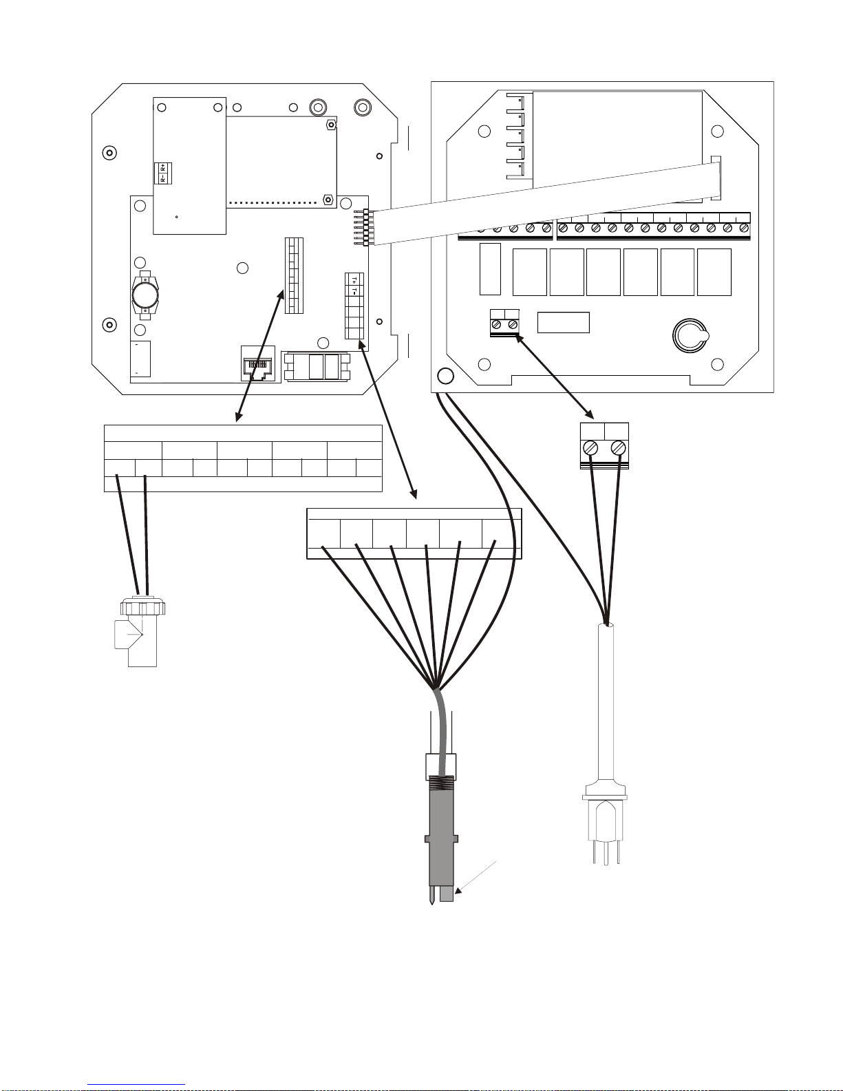
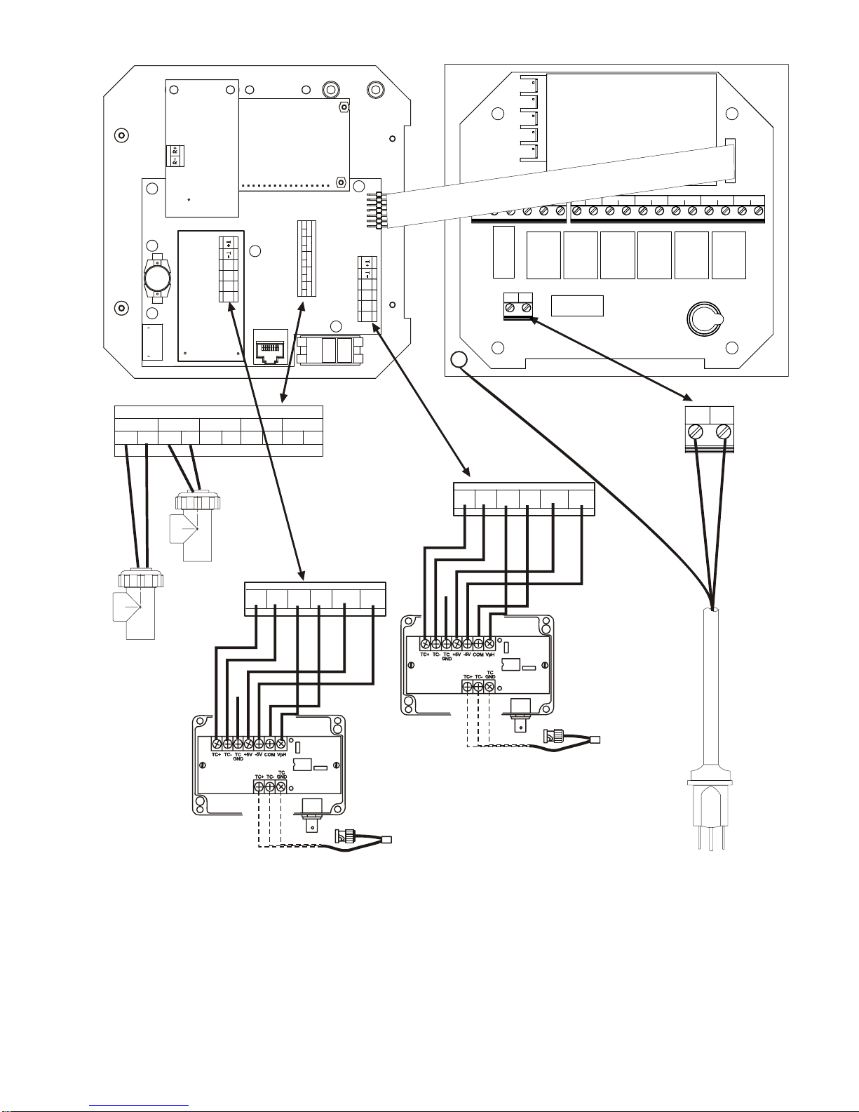
Figure 3a WPH Inputs using WEL pH/ORP Electrode Housings
WEL Electrode
Diffamp Housing
(102581, 102606,
102582,102607,
102758, 102759)
10
SHIELD
pH/ORP electrode
cartridge
Power Supply
(115 VAC or 230 VAC)
L2 L2 L2 L2 L2 L2
IN+
DIG IN 1
IN-
DIG IN 2
IN+
IN-
IN+ IN-
DIG IN 3
IN+ IN-
DIG IN 4
IN+ IN-
DIG IN 5
IN+
IN+5V
-5V
L1 L2/N
BLEED
N.O. N.C.
N.C.
BOI 1
FEED
N.O.N.C.
N.C.
BIO 2
N.O. N.C. N.O.
ALARM
N.O.
N.O.
N.C.
GROUND
STUD
IN-
DIG IN 2
IN+
DIG IN 1
IN+
Contact Closure:
Polarity not critical
Interlock Function
IN-
DIG IN 3
IN+ IN-
DIG IN 4
IN+ IN-
to ground
DIG IN 5
IN+ IN-
T-T+
+5V
G
R
G
N
R
N
1
/
2
Y
0
E
V
L
2
4
0
V
-5VIN+ IN-
B
R
N
2
4
0
V
L1 L2/N
B
L
K
1
2
0
V
WHT 120V
BLU 240V
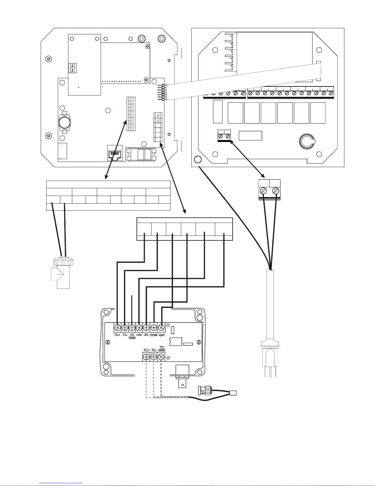
EXTERNAL
PREAMPLIFIER
(190783)
Figure 3b WPH Inputs using pH/ORP Electrode/External Preamplifiers
GROUND
OPTIONAL TEMPERATURE
COMPENSATION (pH ONLY)
Power Supply
(115 VAC or 230 VAC)
11
L2 L2 L2 L2 L2 L2
IN+
DIG IN 1
IN-
DIG IN 2
IN+
ININ+ IN-
IN+
IN+5V
-5V
DIG IN 3
IN+ IN-
DIG IN 4
IN+ IN-
DIG IN 5
IN+
IN+5V
-5V
L2/N
L1
BLEED
N.O. N.C.
N.C.
BOI 1
FEED
N.O.N.C.
N.C.
BIO 2
N.O. N.C. N.O .
ALARM
N.O.
N.O.
N.C.
GROUND
STUD
SYSTEM A
SYSTEM B
T-T+
G
W
R
H
E
I
E
T
N
E
/
G
R
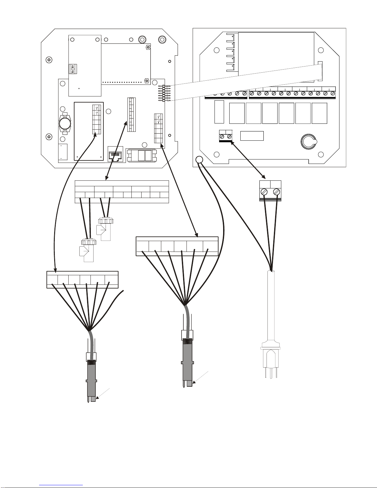
WEL Electrode
Diffamp Housing
(102581, 102606,
102582,102607,
102758, 102759)
DIG IN 1
IN+
O
R
N
N
DIG IN 2
IN-
IN-
IN+
Contact Closure:
Polarity not critical
Interlock Function
+5V
W
B
H
L
H
I
U
T
I
T
E
E
/
O
/
B
R
L
N
U
SHIELD
pH/ORP electrode
cartridge
DIG IN 3
IN+ IN-
SYSTEM B
-5VIN+ IN-
W
DIG IN 4
IN+ IN-
TO GRND
DIG IN 5
IN+ IN-
SYSTEM A
T-T+
G
W
R
H
E
I
E
T
N
E
/
G
R
WEL Electrode
Diffamp Housing
(102581, 102606,
102582,102607,
102758, 102759)
G
R
G
N
R
N
1
2
/
Y
0
E
V
L
2
4
0
V
+5V
-5VIN+ IN-
W
O
R
N
N
B
H
I
T
E
/
O
R
N
W
L
H
U
I
T
E
/
B
L
U
L2/N
L1
B
B
L
R
N
2
4
0
V
K
1
2
0
WHT 120V
BLU 240V
V
SHIELD
pH/ORP electrode
cartridge
Power Supply
(115 VAC or 230 VAC)
Figure 3c WDP Inputs using WEL pH/ORP Electrode Housings
12
DIG IN 1
IN-
IN+
DIG IN 2
IN-
IN+
SYSTEM B
IN+
IN+5V
-5V
DIG IN 3
DIG IN 4
IN+ IN-
IN+ IN-
Contact Closure:
Polarity not critical
Interlock Function
IN+ IN-
T-T+
IN+
DIG IN 1
IN-
DIG IN 2
IN+
ININ+ IN-
DIG IN 3
IN+ IN-
DIG IN 4
IN+ IN-
DIG IN 5
DIG IN 5
SYSTEM B
+5V
BLEED
L2 L2 L2 L2 L2 L2
IN+
IN+5V
-5V
L1 L2/N
FEED
N.C.
N.O. N.C.
N.O.N.C.
BOI 1
N.C.
BIO 2
N.O. N.C. N.O.
ALARM
N.C.
N.O.
N.O.
GROUND
STUD
G
R
G
N
R
1
N
2
/
0
Y
V
E
L
2
4
0
V
SYSTEM A
+5V
T-T+
to ground
-5VIN+ IN-
B
R
N
2
4
0
V
L1 L2/N
B
L
K
1
2
0
V
WHT 120V
BLU 240V
-5VIN+ IN-
Contact Closure:
Polarity not critical
Interlock Function
SYSTEM A
to ground
EXTERNAL
PREAMPLIFIER
(190783)
GROUND
OPTIONAL TEMPERATURE
COMPENSATION (pH ONLY)
EXTERNAL
PREAMPLIFIER
(190783)
GROUND
OPTIONAL TEMPERATURE
COMPENSATION (pH ONLY)
Power Supply
(115 VAC or 230 VAC)
Figure 3d WDP Inputs using pH/ORP Electrode/External Preamplifiers
13
 Loading...