

Walchem WebAlert WA500 Instruction Manual

W
W A L C H E M
IWAKI America Inc.
ebAlert® WA500 Process Monitor
WebAlert® WA500 Series
Process Monitor
Instruction Manual
Five Boynton Road Hopping Brook Park Holliston, MA 01746 USA
TEL: 508-429-1110 FAX: 508-429-7433 WEB: www.walchem.com

Notice
© 2014 WALCHEM, Iwaki America Inc. (hereinafter “Walchem”)
5 Boynton Road, Holliston, MA 01746 USA
(508) 429-1110
All Rights Reserved
Printed in USA
Proprietary Material
The information and descriptions contained herein are the property of WALCHEM. Such information
and descriptions may not be copied or reproduced by any means, or disseminated or distributed
without the express prior written permission of WALCHEM, 5 Boynton Road, Holliston, MA 01746.
This document is for information purposes only and is subject to change without notice.
Statement of Limited Warranty
WALCHEM warrants equipment of its manufacture, and bearing its identification to be free from
defects in workmanship and material for a period of 24 months for electronics and 12 months for
mechanical parts and electrodes from date of delivery from the factory or authorized distributor under
normal use and service and otherwise when such equipment is used in accordance with instructions
furnished by WALCHEM and for the purposes disclosed in writing at the time of purchase, if any.
WALCHEM's liability under this warranty shall be limited to replacement or repair, F.O.B. Holliston,
MA U.S.A. of any defective equipment or part which, having been returned to WALCHEM,
transportation charges prepaid, has been inspected and determined by WALCHEM to be defective.
Replaceable elastomeric parts and glass components are expendable and are not covered by any
warranty.
THIS WARRANTY IS IN LIEU OF ANY OTHER WARRANTY, EITHER EXPRESS OR IMPLIED, AS
TO DESCRIPTION, QUALITY, MERCHANTABILITY, FITNESS FOR ANY PARTICULAR PURPOSE
OR USE, OR ANY OTHER MATTER.
180314 Rev L
July 2014

TABLE OF CONTENTS
1.0 INTRODUCTION ................................................................................................................................ 1
2.0 SPECIFICATIONS ............................................................................................................................. 2
2.1 MEASUREMENT PERFORMANCE ......................................................................................................... 2
2.2 ELECTRICAL ...................................................................................................................................... 2
2.3 MECHANICAL .................................................................................................................................... 3
2.4 VARIABLES AND THEIR LIMITS ............................................................................................................ 3
3.0 UNPACKING & INSTALLATION ...................................................................................................... 4
3.1 UNPACKING THE UNIT ....................................................................................................................... 4
3.2 MOUNTING THE ELECTRONIC ENCLOSURE .......................................................................................... 4
3.3 INSTALLATION ................................................................................................................................... 5
3.4 ICON DEFINITIONS ............................................................................................................................. 5
3.5 ELECTRICAL INSTALLATION ................................................................................................................ 5
4.0 FUNCTION OVERVIEW ............................................................................................................. ..... 11
4.1 FRONT PANEL ................................................................................................................................. 11
4.2 INITIAL STARTUP ............................................................................................................................. 12
4.3 COMMUNICATING WITH THE WEBALERT ............................................................................................ 13
4.4 STARTUP ........................................................................................................................................ 19
4.5 SHUT DOWN ................................................................................................................................... 19
5.0 OPERATION ..................................................................................................................... ............... 19
5.1 MENU SELECTION LINKS ................................................................................................................. 19
5.2 STARTUP ........................................................................................................................................ 20
5.3 SYSTEM SUMMARY MENU ............................................................................................................... 21
5.4 4-20 MA INPUTS ............................................................................................................................. 21
5.5 4-20 MA CALIBRATION .................................................................................................................... 24
5.6 DIGITAL INPUTS .............................................................................................................................. 25
5.7 ALARM ........................................................................................................................................... 29
5.8 SYSTEM STATUS AUTO-REPORTING................................................................................................. 31
5.9 DATALOG AUTO REPORT ................................................................................................................. 31
5.10 ... MANUAL DATALOG .......................................................................................................................... 33
5.11 ... GRAPHING/TRENDING ..................................................................................................................... 34
5.12 ... COMMUNICATIONS MENU ................................................................................................................ 34
5.13 ... ADVANCED COMMUNICATIONS SETTINGS ......................................................................................... 38
5.14 ... SOFTWARE UPGRADE ..................................................................................................................... 40
5.15 ... CONFIGURATION FILE ...................................................................................................................... 40
5.16 ... NOTEPAD ....................................................................................................................................... 41
5.17 ... ACCESS CODES .............................................................................................................................. 41
5.18 ... WALCHEM WEB PAGE ..................................................................................................................... 41
5.19 .. SUB-NETWORK ............................................................................................................................... 42
6.0 MAINTENANCE .............................................................................................................................. 43
6.1 REPLACING THE BATTERY ............................................................................................................... 43
7.0 TROUBLESHOOTING ..................................................................................................................... 44
7.1 ERROR MESSAGES .................................................................................................................... 44
8.0 SERVICE POLICY ................................................................................................................ ........... 47

1.0 INTRODUCTION
WebAlert is the first stand- alone remote monitoring device that can web enable your installed
equipment without having to replace or upgrade it. Your key system parameters (analog and digital
input signals) can now be monitored from any computer – anywhere in the world - with a standard web
browser.
With proprietary on-demand connectivity, the WebAlert is only online when you need it, making it the
world’s first practical and secure industrial monitoring Internet solution. WebAlert pulls your older
equipment into the Internet age with online monitoring, data logging, auto reporting and auto alarming.
User defined alarms can be received by email or cell phone text message. The solid state alarm relay
notifies on-site personnel.
Data logs can be delivered by email as a spreadsheet attachment. You decide where and when you need
the information and WebAlert makes it happen. Since WebAlert supports simultaneous multi-user
access and Ethernet, all of its remote monitoring features are also available on local area networks
(LAN). For larger installations, which require more than six analog and two digital inputs, WebAlerts
can be networked together with Ethernet.
In addition, settings and data may be manipulated using a computer connected directly via USB, or
modem to modem without requiring an Internet connection.
1

2.0 SPECIFICATIONS
2.1 Measurement Performance
4-20 mA Inputs
Range 3.75-20.25 mA
Resolution 0.03 mA
Calibration ± 1 mA
2.2 Electrical
Inputs
Input power 100 – 120/220-240 VAC ±10 % , 1A, 50/60 Hz Fuse 1.0A, 5 x 20mm
Input signals
State-Type Digital Inputs Electrical: Non-Isolated 5 VDC with 301 K ohm pull-up
Typical response time: < 10 seconds
Devices supported: Any isolated dry contact (i.e. relay, reed switch)
Support on inputs: 1 through 6
Types: Generic input
Low Speed Counter-Type Digital
Inputs
High Speed Counter-Type Digital
Inputs
Analog Inputs (1-6) 4-20 mA, 2-wire or 3 -wire, internally powered by 24 VDC, 110 ohm input
Electrical: Non-Isolated 5 VDC with 301 K ohm pull-up, 0-10 Hz, 50 msec
minimum width
Devices supported: Any device with isolated open drain, open collector,
transistor or reed switch
Support on inputs: 1 through 4
Types: Contacting flowmeter, Generic counter
Electrical: Non-Isolated 5 VDC with 301 K ohm pull-up, 0-400 Hz, 1.25 msec
minimum width
Devices supported: Any device with isolated open drain, open collector,
transistor or reed switch
Support on inputs: 1 through 4
Types: Paddlewheel flowmeter, Generic counter
resistance, 1000 ohm maximum load , Typical response time < 10 seconds
Outputs
Solid State Relay: Dry Contact, 0 to 40 VDC, NO AC VOLTAGE, 150 mA maximum load
Digital:
USB
Agency Approvals
Safety UL 61010-1:2012 3rd Ed.
EMC IEC 61326-1:2005
EN 61326-1:2006
Note: For EN61000-4-6, EN61000-4-3 the controller met performance criteria B.
*Class A equipment: Equipment suitable for use in establishments other than domestic, and those
directly connected to a low voltage (100-240 VAC) power supply network which supplies buildings
used for domestic purposes.
Ethernet, 10 Base T
CSA C22.2 No. 61010- 1:2012 3rd Ed.
IEC 61010-1:2010 3rd Ed.
EN 61010-1:2010 3rd Ed.
2

2.3 Mechanical
Enclosure
Material: Polycarbonate
NEMA Rating: NEMA 4X (IP 66)
Dimensions: 32.4 cm x 24.4 cm x 8.3 cm (12.75” x 9.60” x 3.25”)
Operating Ambient Temp: 0 to 60° C (32 to140°F)
Storage Temp: -29 to 80°C (-20 to 176 °F)
Weight 2.0 kg. (4.5 lbs)
2.4 Variables and their Limits
All menus shown may not be available. The menus that appear on your process monitor will vary with
options installed and programmed.
Generic 4-20 mA Input Menu
4 mA = -999,999,999 to 999,999,999 (units of measure defined by user)
20 mA = -999,999,999 to 999,999,999 (units of measure defined by user)
Low Alarm Limit -999,999,999 to 999,999,999 (units of measure defined by user)
High Alarm Limit -999,999,999 to 999,999,999 (units of measure defined by user)
Low-Low Alarm Limit -999,999,999 to 999,999,999 (units of measure defined by user)
High-High Alarm Limit -999,999,999 to 999,999,999 (units of measure defined by user)
Level (4-20 mA) Input Menu
mA when Tank Empty 0 to 20 mA
mA when Tank Full 0 to 20 mA
Full Tank Volume 0 to 999,999,999 (units defined by user)
Low Alarm Limit -999,999,999 to 999,999,999 (units of measure defined by user)
High Alarm Limit -999,999,999 to 999,999,999 (units of measure defined by user)
Low-Low Alarm Limit -999,999,999 to 999,999,999 (units of measure defined by user)
High-High Alarm Limit -999,999,999 to 999,999,999 (units of measure defined by user)
Flow Meter 4-20 mA Input Menu
4 mA = 0 to 999,999,999 (units of flow rate defined by user)
20 mA = 0 to 999,999,999 (units of flow rate defined by user)
Low Alarm Limit 0 to 999,999,999 (units of flow rate defined by user)
High Alarm Limit 0 to 999,999,999 (units of flow rate defined by user)
Low-Low Alarm Limit -999,999,999 to 999,999,999 (units of measure defined by user)
High-High Alarm Limit -999,999,999 to 999,999,999 (units of measure defined by user)
Total Limit 0 to 999,999,999 (units of total volume defined by user)
Digital Input Menu
Paddlewheel Flowmeter Input Menu
K Factor (paddlewheel style) 0.001 to 20,000 (Pulses per Gallon or Liter)
Total Alarm Limit 0 = no limit, otherwise >0
Rate High Alarm >0
Rate Low Alarm >0
Rate High-High Alarm >0
Rate Low-Low Alarm >0
3

Contact Flowmeter Input Menu
Volume per Contact (contact style) 0 to 1000 (units of measure defined by user)
Total Alarm Limit 0 = no limit, otherwise >0
Counter Input Menu
One Count = >0
Total Alarm Limit 0 =no limit, otherwise >0
Rate High Alarm >0
Rate Low Alarm >0
Rate High-High Alarm >0
Rate Low-Low Alarm >0
Alarm Output Menu
Remote Alarm Delay Time 1 to 1440 minutes
Output Time Limit 0 to 1440 minutes (0 = no limit)
Alarm Hand Time Limit 1 to 1440 minutes
Auto Reporting Menu
Logging Frequency 10 to 1440 minutes
Access Code Menu
Session Timeout 0 to 60 minutes (0 = infinity)
3.0 UNPACKING & INSTALLATION
3.1 Unpacking the Unit
Inspect the contents of the carton. Please notify the carrier immediately if there are any signs of damage
to the process monitor or its parts. Contact your distributor if any of the parts are missing. The carton
should contain a WebAlert series process monitor and instruction manual. Any options or accessories
will be incorporated as ordered.
3.2 Mounting the Electronic Enclosure
The WebAlert series process monitor is supplied with mounting holes on the enclosure. It should be
wall mounted with the display at eye level on a vibration-free surface, utilizing all mounting holes for
maximum stability.
The enclosure is IP66 (NEMA 4X) rated, suitable for outdoor installation. The maximum ambient
operating temperature is 60 degrees C (140 degrees F); this should be considered if installation is in a
high temperature location.
The installation site should be in close proximity to grounded AC power, the devices to be connected,
and phone line or Ethernet hub (if applicable).
Avoid locations that are in close proximity to sources of electrical noise (motor starters, power
transformers, variable speed motor drives, radio transmitters, etc.), corrosive fumes or excessive
moisture.
4
The enclosure requires the following clearances:
Top: 5 cm (2”)
Left: 10 cm (4”)
Right: 10 cm (4”)
Bottom: 10 cm (4”)
3.3 Installation
The WebAlert receives digital and analog input signals, and sends a digital output signal. The
maximum distances for these cables, using 24 AWG shielded twisted pair cable, is 1200 meters (4000
feet) for the 4-20 mA input signals and 300 meters (1000 feet) for the digital input and output signals. It
is highly recommended that these cables be routed separately from any AC voltage wires, and that the
cable shield drain wire is connected to earth ground at the process monitor end only.
Note: Using the WebAlert process monitor in any manner other than that specified in this manual could
compromise the safety of persons or property.
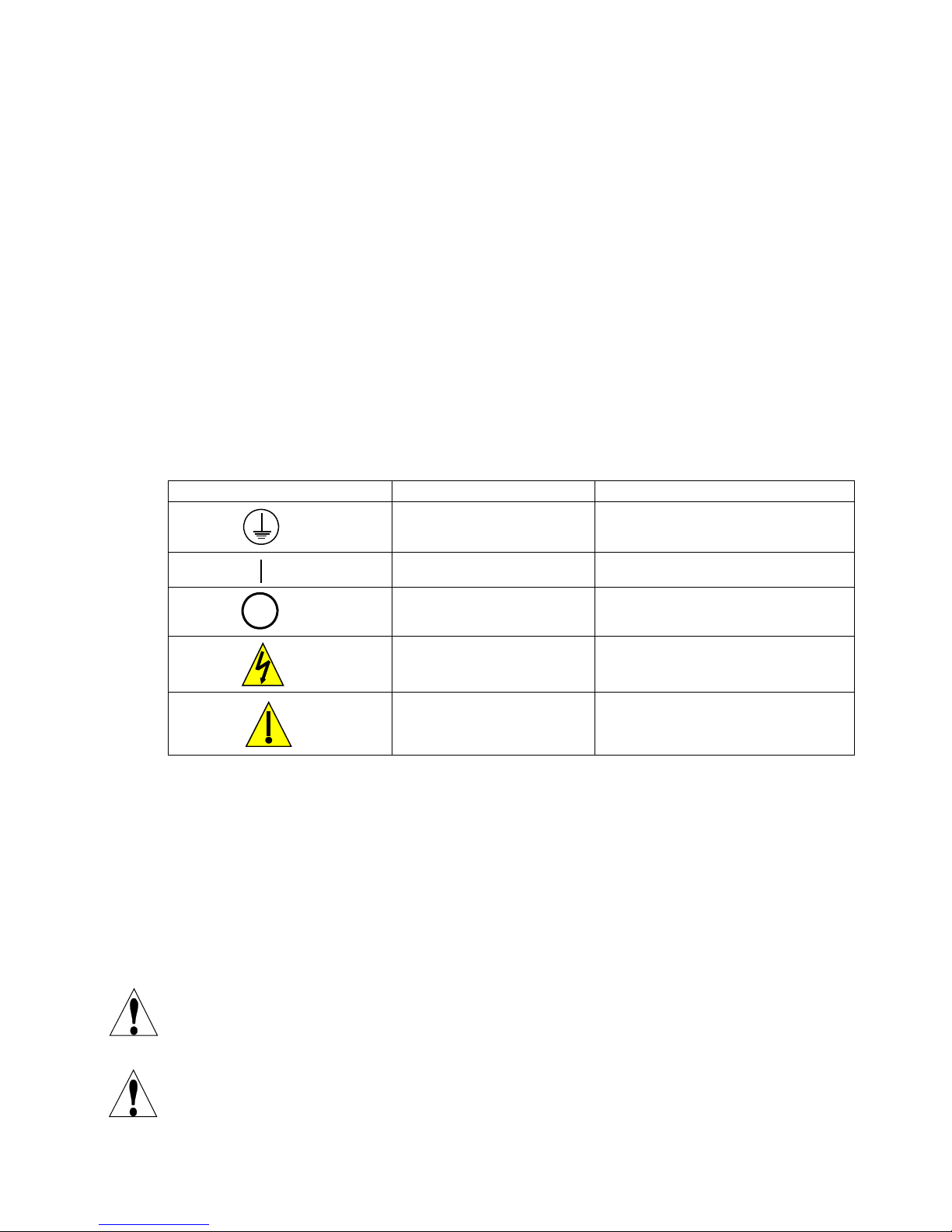
3.4 Icon Definitions
Symbol Publication Description
IEC 417, No.5019 Protective Conductor Terminal
IEC 417, No. 5008 Off (Supply)
3.5 Electrical Installation
The WebAlert series process monitors require the following voltages:
100 –120/200-240 VAC ± 10%, 50/60 Hz, 1.0 amperes maximum.
Your unit is supplied ready to be hardwired. In addition, you will be required to hardwire some or all of
the input/output devices. Please refer to Figures 2 through 5 for wiring diagrams.
Note: Proper grounding of this product is required. Any attempt to bypass the grounding will
compromise the safety of persons and property.
CAUTION! There are live circuits beneath the power supply cover! The process monitor must not be
operated without this cover properly installed!
CAUTION! The electrical installation of the process monitor must be done by trained personnel only
and conform to all applicable National and Local codes!
IEC 417, No. 5007 On (Supply)
ISO 3864, No. B.3.6 Caution, risk of electric shock
ISO 3864, No. B.3.1 Caution
5
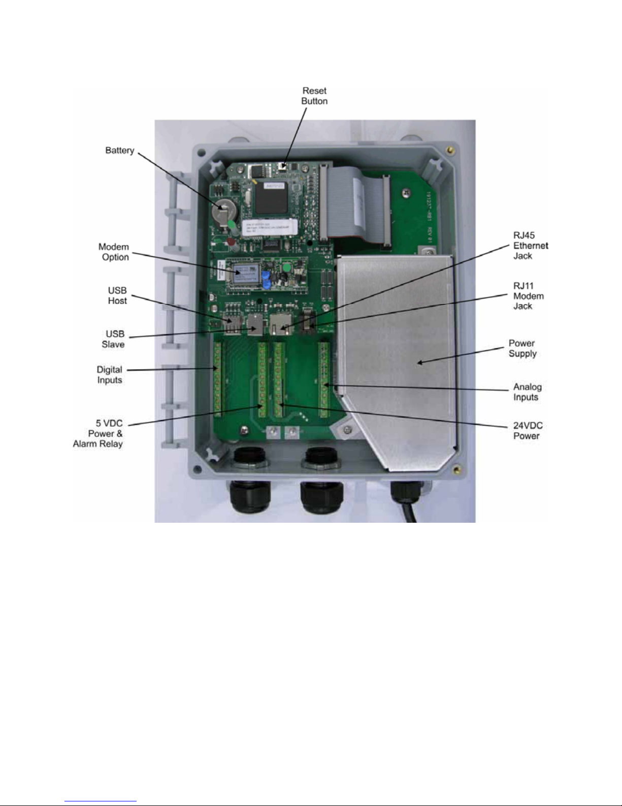
Figure 1 Identification of Parts
6
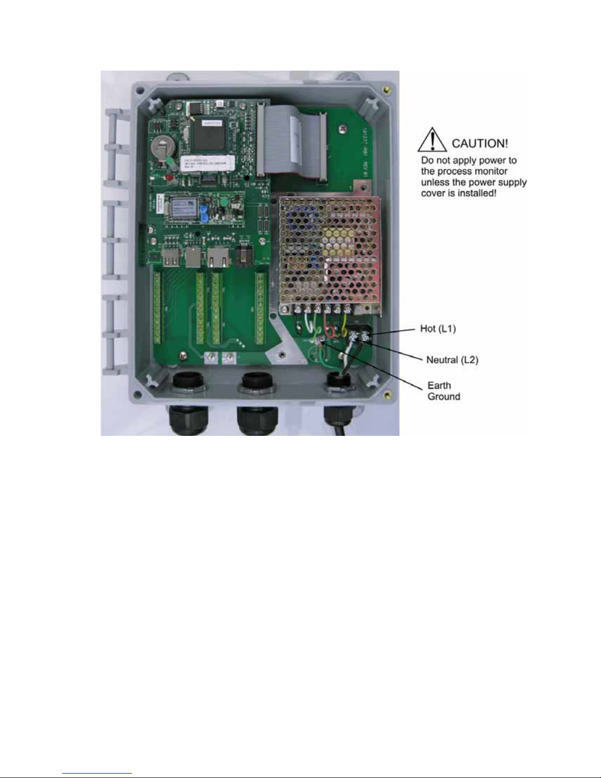
Figure 2 – Wiring Diagram for AC Power Input
7
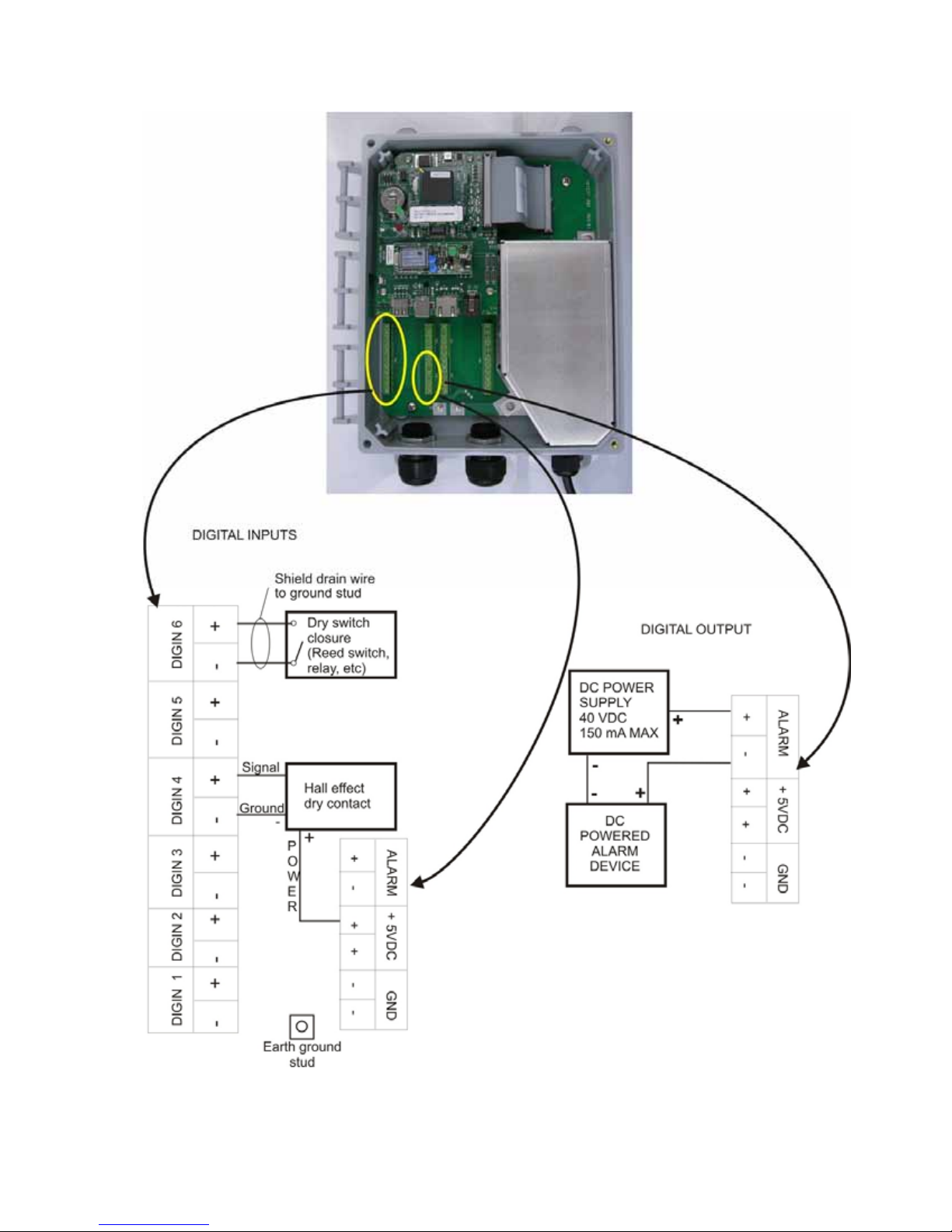
Figure 3 - Wiring Diagram for Digital Inputs and Outputs
8
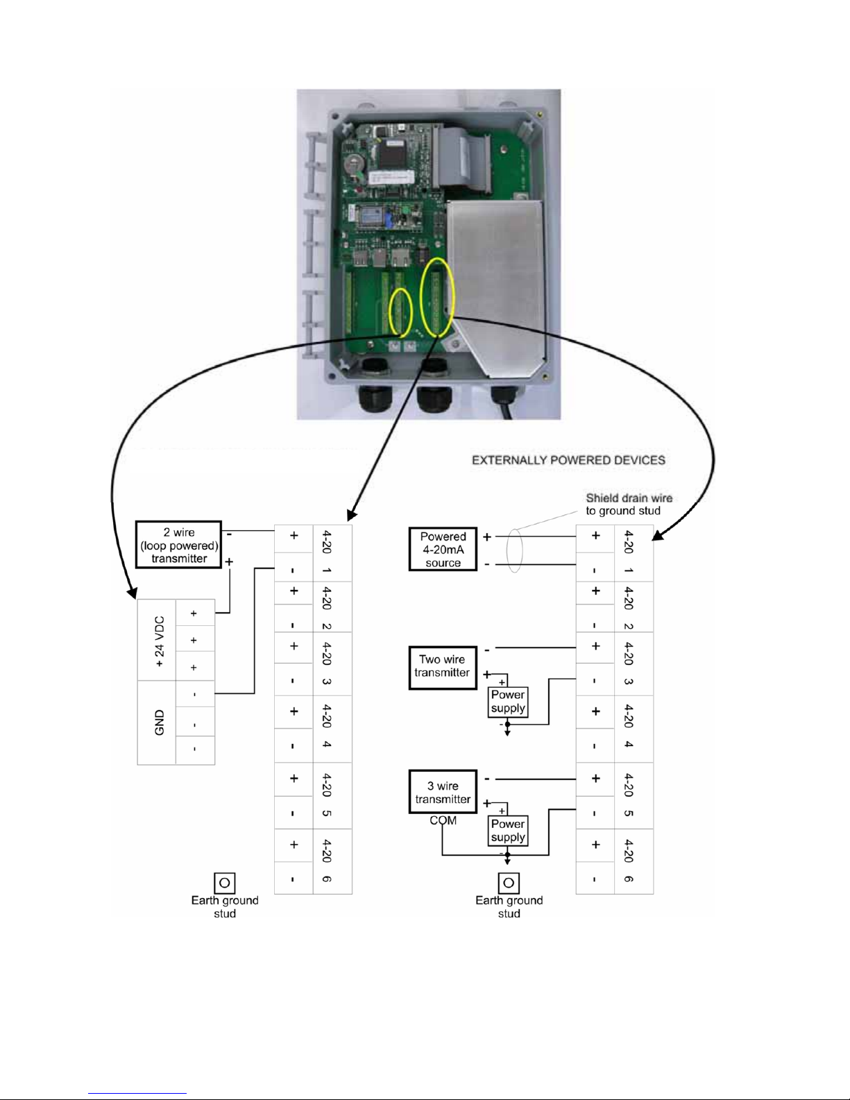
DEVICES POWERED BY THE WEBALERT
Figure 4 - Wiring Diagram for Analog Inputs
9
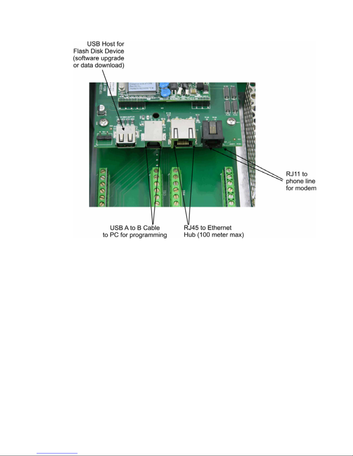
Figure 5 – Wiring Diagram for USB Devices and Communications
10

4.0 FUNCTION OVERVIEW
4.1 Front Panel
Status LED
Alarm LED
11

4.2 Initial Startup
Turn the power on. Be patient, the start up sequence will take about the same time as it takes a
computer to boot up, approximately 2 minutes. The Status LED will flash, and when boot up is
complete the WebAlert will beep 3 times. Under normal conditions, the Status LED will flash on and
off every second.
The WebAlert Series process monitors have a wide range of capabilities, so the steps required preparing
the site for installation would be different depending upon the capability you will be using.
If you want to program the WebAlert using a laptop computer to connect to the serial port on the front
panel of the unit, go to the section below called “Direct Connection to the USB Port”.
If you have a unit that is equipped with a modem, then you can take full advantage of the WebAlert.
The unit is like a web server. Once you set up an Internet Service Provider (ISP) account for the unit,
you can “surf” to it from any web connected computer to access data or reconfigure the settings. The
unit can also contact you, by email or cell phone text message, in case of trouble. In this case, a
dedicated analog phone line that does not go through a company switchboard for the process monitor
must be provided. For details, go to the section below called “Remote Modem Access: Shoulder Tap.”
The ISP information must be entered into the WebAlert via direct connection to the USB port, via
Ethernet or via the Direct Modem method before attempting a Shoulder Tap connection.
If you have not yet set up an ISP account and wish to program the WebAlert from a remote location, or
if you just prefer the “old fashioned method” of direct modem-to-modem communication, go to the
section below called “Direct Modem Access: Direct Tap.”
If you can use the Ethernet connection installed, then the WebAlert becomes like another device on a
network. You can use your web browser software, enter the unit’s address (assigned by your network
administrator) and access data or reconfigure the unit. You will need to have a network node nearby
(within 100 meters/330 feet) to connect your WebAlert process monitor. See the section below called
“Ethernet Connection to LAN”.
You may also use the Ethernet card in your laptop to communicate with the Ethernet connection in the
WebAlert. This requires a special null cable and the laptop network settings must be configured to
work with the WebAlert. Refer to the section below called “Direct Ethernet (for a WebAlert not
connected to the LAN).”
Uploading Configuration Files
You can save all of the set points from a previously programmed unit, and then import the same set
points into another unit. If you have already exported a configuration file from a previously
programmed unit, you can import that file to this unit in order to make all the set points the same. If you
want to save the set points of this unit for use in future units, or want to program this unit using a stored
configuration file, refer to section 5.14 for specific instructions.
See the appropriate section above, depending upon how you plan on exporting the configuration file;
via a laptop connected to the front panel, via modem, or via Ethernet connection.
12
4.3 Communicating with the WebAlert
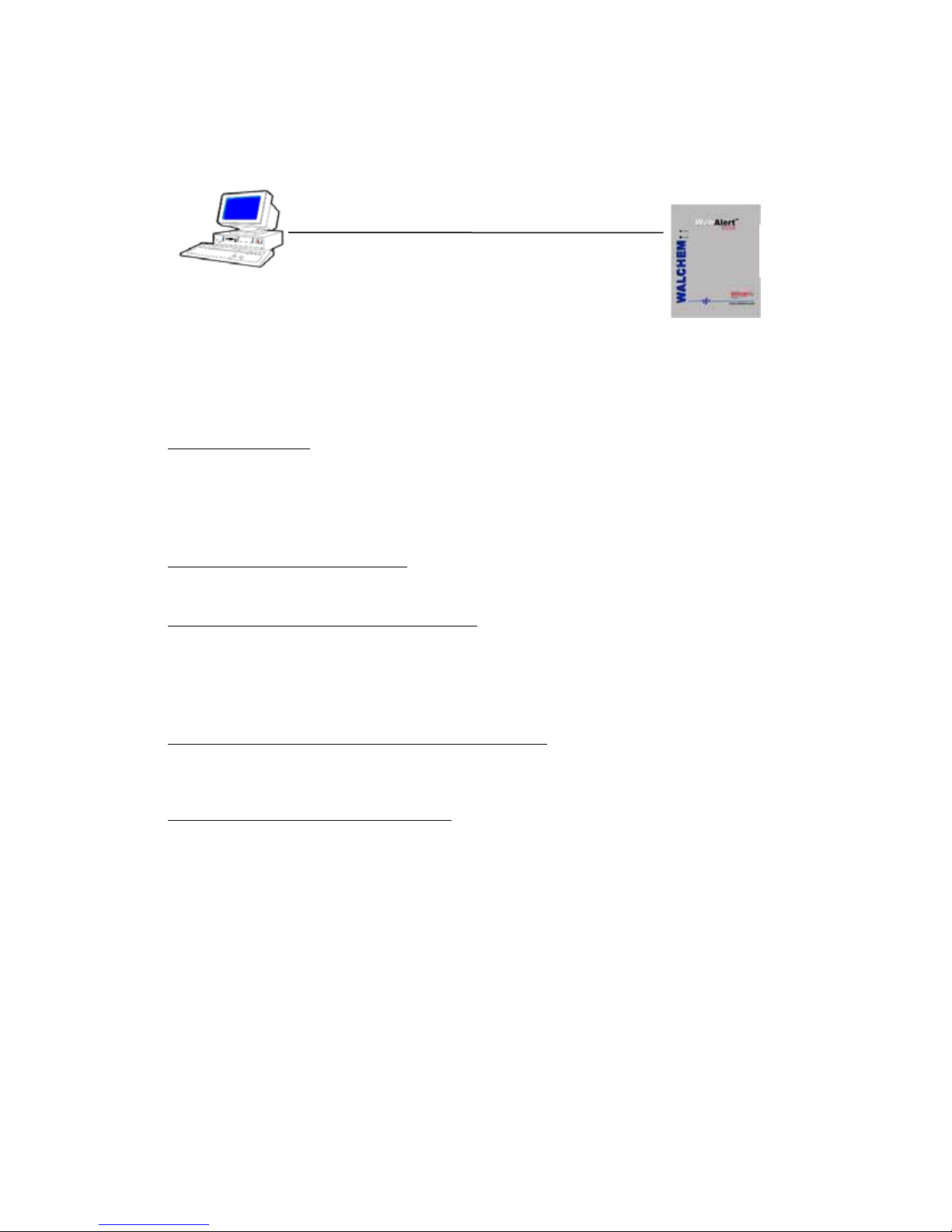
4.3.1 Direct Connection to the USB Port
Web Browser
(Client)
USB
Hard coded Fixed
IP Address:
199.199.199.2
A direct USB connection to the WebAlert can be made in two ways. A temporary connection or a
permanent connection can be made between a PC and the USB connector inside the unit. The cable
length is limited to 5 meters (15 feet).
Equipment Required
An A to B USB cable.
An Internet-ready computer with the following capabilities: 100 MHz minimum processor speed,
40 MB minimum RAM, Windows 2000 or newer operating system, and Windows Internet Explorer
version 5.0 or higher web browser software.
Features Required in the WebAlert
Any WebAlert process monitor is capable of an USB connection.
Utilities you need to set up on your computer
An USB driver must be installed on your computer. Refer to the separate detailed instructions for
this procedure.
A Local Area Connection must be configured in order to establish a communication between the
process monitor and your PC. See below for this procedure.
Parameters that need to programmed into the WebAlert
The WebAlert is capable of this type of communication without any programming by the user prior
to attempting the communication.
Steps Required to Establish a Connection
Connect the USB cable between the WebAlert and your computer. A New Hardware Found wizard
will launch.
Install the driver on your PC by inserting the disc supplied and following the instructions. This
needs to done only once for each PC that will be used to communicate with a WebAlert process
monitor.
Go to Control Panel, Network Connections, and locate the new Local Area Connection 2 that has
been created. Click on the Properties button. Highlight Internet Protocol (TCP/IP) then click
Properties. Click Use the following IP address and enter 199.199.199.1. Click OK to exit.
Open Internet Explorer and type in the address 199.199.199.2.
The sign-on screen of the WebAlert will come up. Type the User Name and Password (Access
Code) in the text boxes and click the Submit button. The default user name is "webalert" and the
default passwords are "2001" for full access, "2002" for calibration only, and "2003" for read only.
These defaults can and should be changed in the Access Code page.
13
 Loading...