

Walchem WDT400 Series Instruction Manual

W
W A L C H E M
IW AKI America Inc.
DT400 Controllers
WDT400 Series
Dual Cooling Tower
Conductivity Controller
Instruction Manual
Five Boynton Road Hopping Brook Park Holliston, MA 01746 USA
TEL: 508-429-1110 FAX: 508-429-7433 WEB: www.walchem.com

Notice
© 2014 WALCHEM, Iwaki America Inc.(hereinafter “Walchem”)
Five Boynton Road, Holliston, MA 01746 USA
(508) 429-1110
All Rights Reserved
Printed in USA
Proprietary Material
The information and descriptions contained herein are the property of WALCHEM. Such information and
descriptions may not be copied or reproduced by any means, or disseminated or distributed without the
express prior written permission of WALCHEM, Five Boynton Road, Holliston, MA 01746.
Statement of Limited Warranty
WALCHEM warrants equipment of its manufacture, and bearing its identification to be free from
defects in workmanship and material for a period of 24 months for electronics and 12 months for
mechanical parts and electrodes from date of delivery from the factory or authorized distributor
under normal use and service and otherwise when such equipment is used in accordance with
instructions furnished by WALCHEM and for the purposes disclosed in writing a the time of
purchase, if any. WALCHEM’s liability under this warranty shall be limited to replacement or
repair, F.O.B. Holliston, MA U.S.A. of any defective equipment or part which, having been
returned to WALCHEM, transportation charges prepaid, has been inspected and determined by
WALCHEM to be defective. Replacement elastomeric parts and glass components are expendable
and are not covered by any warranty.
THIS WARRANTY IS IN LIEU OF ANY OTHER WARRANTY, EITHER EXPRESS OR IMPLIED,
AS TO DESCRIPTION, QUALITY, MERCHANTABILITY, and FITNESS FOR ANY
PARTICULAR PURPOSE OR USE, OR ANY OTHER MATTER.
180331 Rev. L
April 2014

Table of Contents
1.0 INTRODUCTION..................................................................................................................... 1
2.0 SPECIFICATIONS .................................................................................................................. 2
2.1 Measurement Performance ................................................................................................. 2
2.2 Electrical: Input/Output ........................................................................................................ 2
2.3 Mechanical .......................................................................................................................... 2
2.4 WDT Variables and their Limits ........................................................................................... 3
3.0 UNPACKING & INSTALLATION ............................................................................................. 4
3.1 Unpacking the unit............................................................................................................... 4
3.2 Mounting the electronic enclosure....................................................................................... 4
3.3 Installation ........................................................................................................................... 4
3.4 Icon Definitions.................................................................................................................... 6
3.5 Electrical installation............................................................................................................ 6
4.0 FUNCTION OVERVIEW ....................................................................................................... 10
4.1 Front Panel........................................................................................................................ 10
4.2 Display .............................................................................................................................. 10
4.3 Keypad .............................................................................................................................. 11
4.4 Access Code ..................................................................................................................... 11
4.5 Startup............................................................................................................................... 11
4.6 Shut Down......................................................................................................................... 11
5.0 OPERATION ......................................................................................................................... 12
5.1 Main Menu ........................................................................................................................ 12
5.2 Conductivity (A or B) Menu ............................................................................................... 14
5.3 Temperature (A or B) Menu .............................................................................................. 16
5.4 Bleed (A or B) Menu .......................................................................................................... 17
5.5 Feed (A or B) Menu ........................................................................................................... 18
5.6 WM1 and WM2 Menu........................................................................................................ 20
5.7 Alarm (A or B) Menu.......................................................................................................... 21
5.8 Time Menu ........................................................................................................................ 22
5.9 4-20mA (A or B) Menu ...................................................................................................... 23
5.10 Access Code Menu ........................................................................................................... 24
5.11 Datalog Menu.................................................................................................................... 25
5.12 Config Menu...................................................................................................................... 26
5.13 Upgrade Menu .................................................................................................................. 27
6.0 MAINTENANCE .................................................................................................................... 28
6.1 Electrode Cleaning............................................................................................................ 28
6.2 Replacing the Fuses.......................................................................................................... 29
7.0 TROUBLESHOOTING .......................................................................................................... 29
7.1 Error Messages................................................................................................................. 29
7.2 Conductivity Readout Does Not Change........................................................................... 31
7.3 Procedure for evaluation of the conductivity electrode ..................................................... 31
7.4 Procedure for checking relay outputs ................................................................................ 32
8.0 SERVICE POLICY ................................................................................................................ 32

1.0 INTRODUCTION
The Walchem WDT400 Series controllers offer conductivity control of cooling tower water and control
of corrosion/scale inhibitor feed. The inhibitor pump may be selected to operate in one of the following
modes:
The WDT series cooling tower controllers are supplied with temperature compensated electrodes with a
cell constant of 1.0. The controllers are microprocessor driven industrial type with on/off control
outputs. A timed sample mode may be selected, and on small towers can reduce installation costs by
eliminating the need for a sampling bypass line. One or two optional isolated 4-20 mA outputs that are
proportional to the conductivity reading are available for all models.
Any set point may be viewed without interrupting control. Each set point change will take effect as soon
as it is entered. An access code is available to protect set point parameters, while still allowing settings
to be viewed.
All outputs are interlocked with a flow switch input.
An alarm relay is provided with WDT400 models. It is triggered by:
Our unique USB feature provides the ability to upgrade the software in the controller to the latest
version.
An advanced USB capability option is available. The Config file feature allows you to save all the set
points from a controller onto a USB flash disk, and then import them into another controller, making the
programming of multiple controllers fast and easy. The data logging feature allows you to save the last
2 month’s readings and events to a USB flash disk.
Feed and Bleed
Feed and Bleed with Lockout
Feed as a percent of Bleed
Feed as a percent of Time
Feed based on a Water Contactor input
Feed based on a Paddlewheel input
Temp A or B Error
Cond A or B Error
No Flow Tower A or B
Bleed A or B Timeout
Feed A or B Timeout
Tower A or B Hi Alarm
Tower A or B Lo Alarm
1

2.0 SPECIFICATIONS
2.1 Measurement Performance
Conductivity Range 0 - 10,000 µS/cm (microSiemens/centimeter)
Conductivity Resolution 1 µS/cm
Conductivity Accuracy 10 - 10,000 µS/cm ± 1% of reading
Temperature Range 32 – 158°F (0 – 70°C)
Temperature Resolution 0.1°C
Temperature Accuracy ± 1% of reading
2.2 Electrical: Input/Output
Input Power
Input Signals
Conductivity Electrode 1.0 cell factor, 10K thermistor
Flow Meter (0, 1 or 2 optional) Isolated, dry contact closure required (i.e. relay, reed switch)
Flow Switch (0, 1 or 2 optional) Isolated, dry contact closure required (i.e. reed switch)
Outputs
Mechanical Relays (5) Pre-powered on circuit board switching line voltage
0 - 10 µS/cm ± 20% of reading
100-240 VAC, 50/60 Hz, 8A
Fuse: 1.0 ampere, 5 x 20 mm
6 A (resistive), 1/8 HP
All relays are fused together as one group, total current for this
group must not exceed 6A
4 - 20 mA (0,1, or 2 optional) Fully isolated
Agency Approvals
Safety UL 61010-1:2012 3rd Ed.
Note: For EN61000-4-6, EN61000-4-3 the controller met performance criteria B.
*Class A equipment: Equipment suitable for use in establishments other than domestic, and those directly
connected to a low voltage (100-240 VAC) power supply network which supplies buildings used for
domestic purposes.
600 Ohm max resistive load
Resolution .001% of span
Accuracy ± 1% of reading
CSA C22.2 No. 61010-1:2012 3rd Ed.
IEC 61010-1:2010 3rd Ed.
EN 61010-1:2010 3rd Ed.
EMC IEC 61326-1:2005
EN 61326-1:2006
2.3 Mechanical
Enclosure Material Polycarbonate
NEMA Rating NEMA 4X
Dimensions 8.5" x 6.5" x 5.5"
Display 2 x 16 character backlit liquid crystal
Operating Ambient Temp 32 – 122°F (0 – 50°C)
Storage Temperature -20 – 180°F (-29 – 80°C)
Graphite electrode pressure rating 150 psi
Flow switch manifold pressure rating 150 psi
Flow switch manifold connections ¾" NPTF
2

2.4 WDT Variables and their Limits
Low Limit High Limit
Conductivity menu
Temperature Menu
Bleed Menu
Feed Menu
WM1 and WM2 Menus
K Factor (Paddlewheel) 0.01 pulse/vol 999.99 pulses/vol
4-20 mA Menus 4 & 20 mA Settings 0 µS/cm 10,000 µS/cm
Access Code New Value 0 9999
Alarms Menu* High & Low (set to zero to disable) 1% 50%
Datalog Menu (Optional)
Config Menu (Optional)
Upgrade Menu
*Note: The Alarm relay is non-programmable. Refer to the Main Menu diagram on page 16 for the list of error
conditions that trigger the alarm relay.
Bleed Limit Time (set in hours/minutes) 1 minute 8 hrs: 20 min
PPM Conversion Factor 0.200 ppm/µS/cm 1.000 ppm/µS/cm
Interval Time (sampling) 5 minutes 24:00 hours
Duration Time (sampling) 1 minute 59 min: 59 sec
% Calibration Range -50 +50
Set Point 0 µS/cm 10,000 µS/cm
Dead Band 5 µS/cm 500 µS/cm
Feed Lockout Timer (Mode A) 1 second 99 min: 59 sec
Percent of Bleed (Mode B) 5 % 99 %
Feed Time Limit (Mode B) 1 minute 99 min: 59 sec
Percent of Time (Mode C) 5 % 99 %
Feed Cycle Time (Mode C) 10 minutes 59 min: 59 sec
Time per Contact (Mode D) 1 second 59 min: 59 sec
÷ Contacts by (Mode D) 1 contact 100 contacts
Time Limit (Mode D & E) 1 minute 99 min: 59 sec
Time/Vol (Mode E) 1 second 59 min: 59 sec
Vol to Initiate Feed (Mode E) 1 9,999
Gallons per Contact 1 gal/contact 500 gal/contact
Liters per Contact 1 L/contact 500 L/contact
No variables
No variables
No variables
No variables
(enabled)
0=unlimited (disabled)
3

3.0 UNPACKING & INSTALLATION
3.1 Unpacking the unit
Inspect the contents of the carton. Please notify the carrier immediately if there are any signs of damage
to the controller or its parts. Contact your distributor if any of the parts are missing. The carton should
contain: a WDT400 series controller and instruction manual. Any options or accessories will be
incorporated as ordered.
3.2 Mounting the electronic enclosure
The WDT series controller is supplied with mounting holes on the enclosure. It should be wall mounted
with the display at eye level, on a vibration-free surface, utilizing all four mounting holes for maximum
stability. Use M6 (1/4" diameter) fasteners that are appropriate for the substrate material of the wall.
The enclosure is NEMA 4X rated. The maximum operating ambient temperature is 122°F (50°C); this
should be considered if installation is in a high temperature location. The enclosure requires the
following clearances:
Top: 2" (50 mm)
Left: 8" (203 mm)
Right: 4" (102 mm)
Bottom: 7" (178 mm)
3.3 Installation
Once the WDT series controller is mounted, the metering pumps may be located at any distance from
the controller. The conductivity electrodes should be placed as close to the controller as possible, to a
maximum distance of 250 ft. Under 25 ft is recommended. The cable must be shielded from background
electrical noise. Always route low voltage (sensor) signals with at least a 6” separation from AC voltage
wiring.
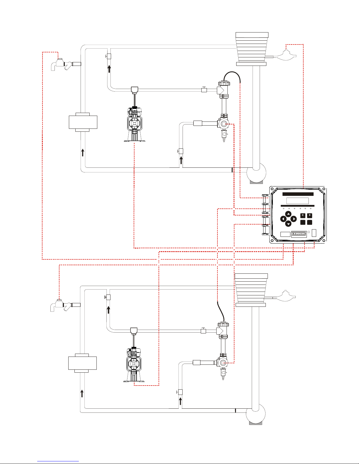
Locate the electrode tees where an active sample of cooling tower water is available and where the
electrode can easily be removed for cleaning. They must be situated so that the tee is always full and the
electrode is never subjected to a drop in water level resulting in dryness. Refer to Figure 1 for typical
installation.
IMPORTANT: To avoid cracking the female pipe threads on the supplied plumbing parts, use no more
than 3 wraps of Teflon® tape and thread in the pipe FINGER tight plus ½ turn! Do not use pipe dope to
seal the threads of the flow switch because the clear plastic will crack!
4
COO
LING TOWER
BLEED
VALVE
EXCHANGER
HEAT
System A
METERING
PUMP
Cooling Tower Controller
PRE V N EXT
ENTER
www.wal chem.com
I
EX T
COOLING TOWER
BLEED
VALVE
EXCHANGER
HEAT
METERING
PUMP
System B
Figure 1 Typical Installation
5
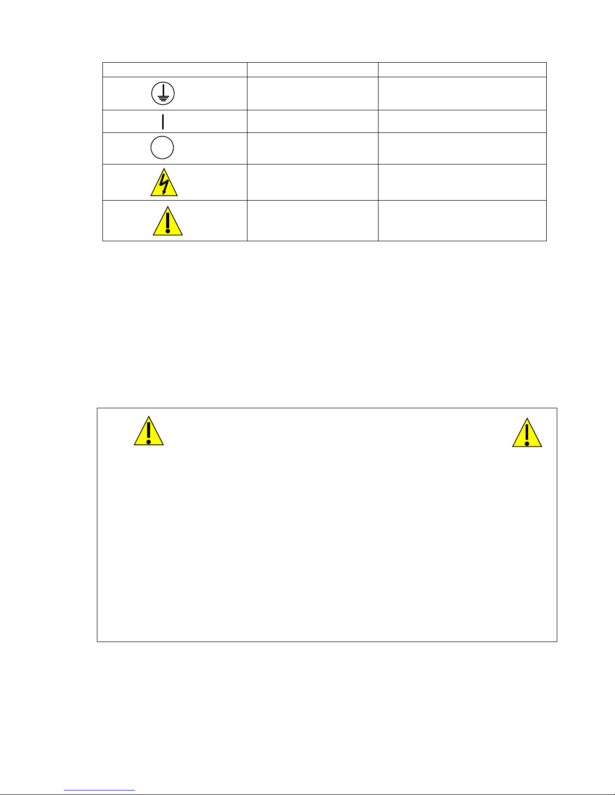
3.4 Icon Definitions
Symbol Publication Description
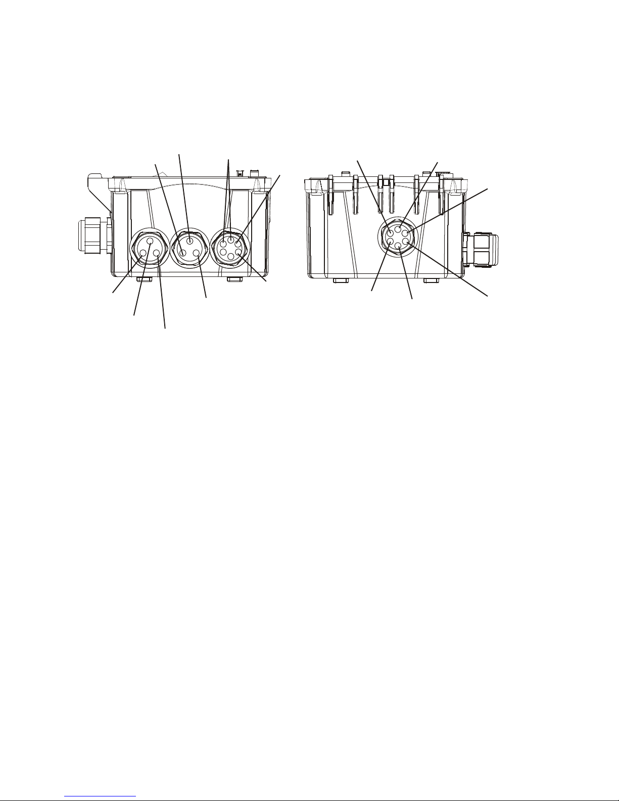
3.5 Electrical installation
The various standard wiring options are shown in figure 2, below. Your WDT series controller will
arrive from the factory prewired or ready for hardwiring. Depending on your configuration of controller
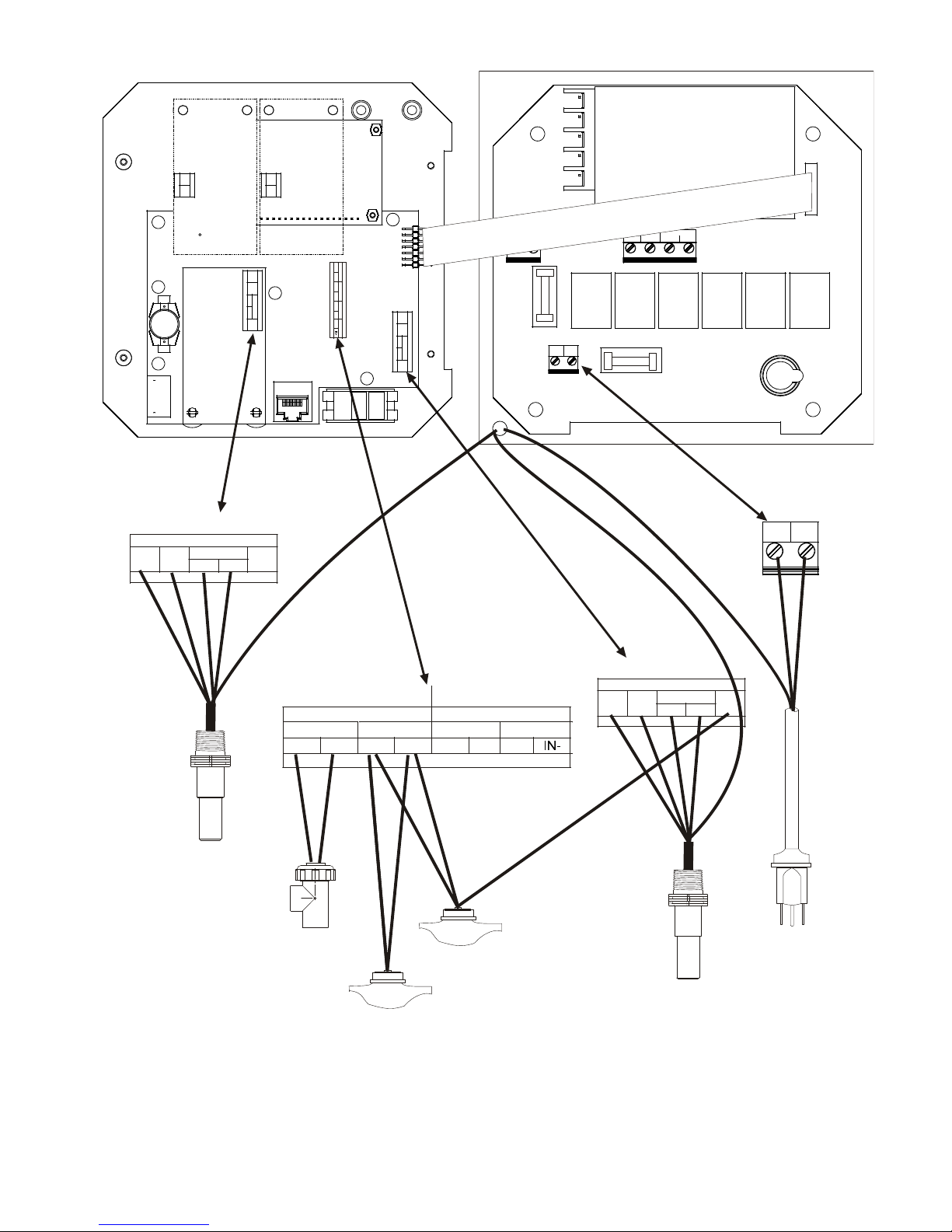
options, you may be required to hardwire some or all of the input/output devices. Refer to figures 3 and
4 for circuit board layout and wiring.
Note: when wiring the optional flow meter contactor input, the 4-20 mA output or a remote flow switch,
it is advisable to use stranded, twisted, shield pair wire between 22-26 AWG. Shield should be
terminated at the controller ground stud (see figures 3 and 4).
IEC 417, No.5019 Protective Conductor Terminal
IEC 417, No. 5007 On (Supply)
IEC 417, No. 5008 Off (Supply)
ISO 3864, No. B.3.6 Caution, risk of electric shock
ISO 3864, No. B.3.1 Caution
CAUTION
1. There are live circuits inside the controller even when the power switch on the front panel is in
the OFF position! The front panel must never be opened before power to the controller is
REMOVED!
If your controller is prewired, it is supplied with a 8 foot, 18 AWG power cord with USA style
plug. A tool (#1 Phillips driver) is required to open the front panel.
2. When mounting the controller, make sure there is clear access to the disconnecting device!
3. The electrical installation of the controller must be done by trained personnel only and
conform to all applicable National, State and Local codes!
4. Proper grounding of this product is required. Any attempt to bypass the grounding will
compromise the safety of persons and property.
5. Operating this product in a manner not specified by Walchem may impair the protection
provided by the equipment.
6
BLEED B
Y
CO
FEED B
SPARES
4-20 mA (2)
(optional)
CONDUCTIVIT
ELECTRODE B
NDUCTIVITY
ELECTRODE A
FLOW SWITCH A
(OPTIONAL)
POWER
BLEED A
FEED A
ALARM
4-20 mA (1)
(optional)
FLOW METER B
(OPTIONAL)
Figure 2 Conduit/Wiring Configuration
FLOW SWITCH B
(OPTIONAL)
FLOW METER A
(OPTIONAL)
7
T+ T-
G
R
E
E
N
R- R+
SYSTEM B
COND
RED BLK
W
H
I
T
E
T+ T-
RED BLK
+5V
+5V
COND
R- R+
BLEED
L2 L2
IN+ IN-
FLOW SW 1 FLOW SW 2
FLOW M TR 1
IN+ IN-
IN+ IN- IN+
FL O W M TR 2
T+ T-
RED BLK
COND
+5V
F1
L1 L2/N
N.C. N.O.
FEED
N.C. N.O.
F2
GROUND
STUD
GR
GR
N
1
N
2
/
Y
0
V
E
L
2
4
0
V
L1 L2/N
B
B
LK
R
N
120V
2
40V
WHT 120V
BLU 240V
SHIELD
FLOW SW 1 FLOW SW 2
IN+ IN- IN+ IN- IN+
Conductivity
Electrode
Contact Closure:
Polarity not critical
SYSTEM A
FLOW MTR 1
IN+ IN-
Flow Meter
Reed Switch
Flow Meter
Polarity not Critical
Figure 3 Inputs
SYSTEM B
Hall Effect
FLOW MTR 2
T+ T-
G
R
E
E
N
SYSTEM A
COND
RED BLK
W
H
I
T
E
Conductivity
Electrode
+5V
SHIELD
Power Supply
(115 VAC or 230 VAC)
8
System
A
A
p
p
Chart Chart
Recorder Recorder
System B
T+ T-
RED BLK
COND
+5V
IN+ IN- IN+ IN- IN +
IN+ IN-
GRN 120V
GRN/YEL 240V
L2/N L2/N L2/N L2/N L2/N L2/N
WHT 120V
BLU 240V
WHT 120V
BLU 240V
WHT 120V
WHT 120V
BLU 240V
BLU 240V
L2 L2 L2 L2 L2 L2
FLOW SW 1 FLOW SW 2
FLOW MTR 1 FLOW MTR 2
T+ T-
RED BLK
COND
+5V
L1 L2/N
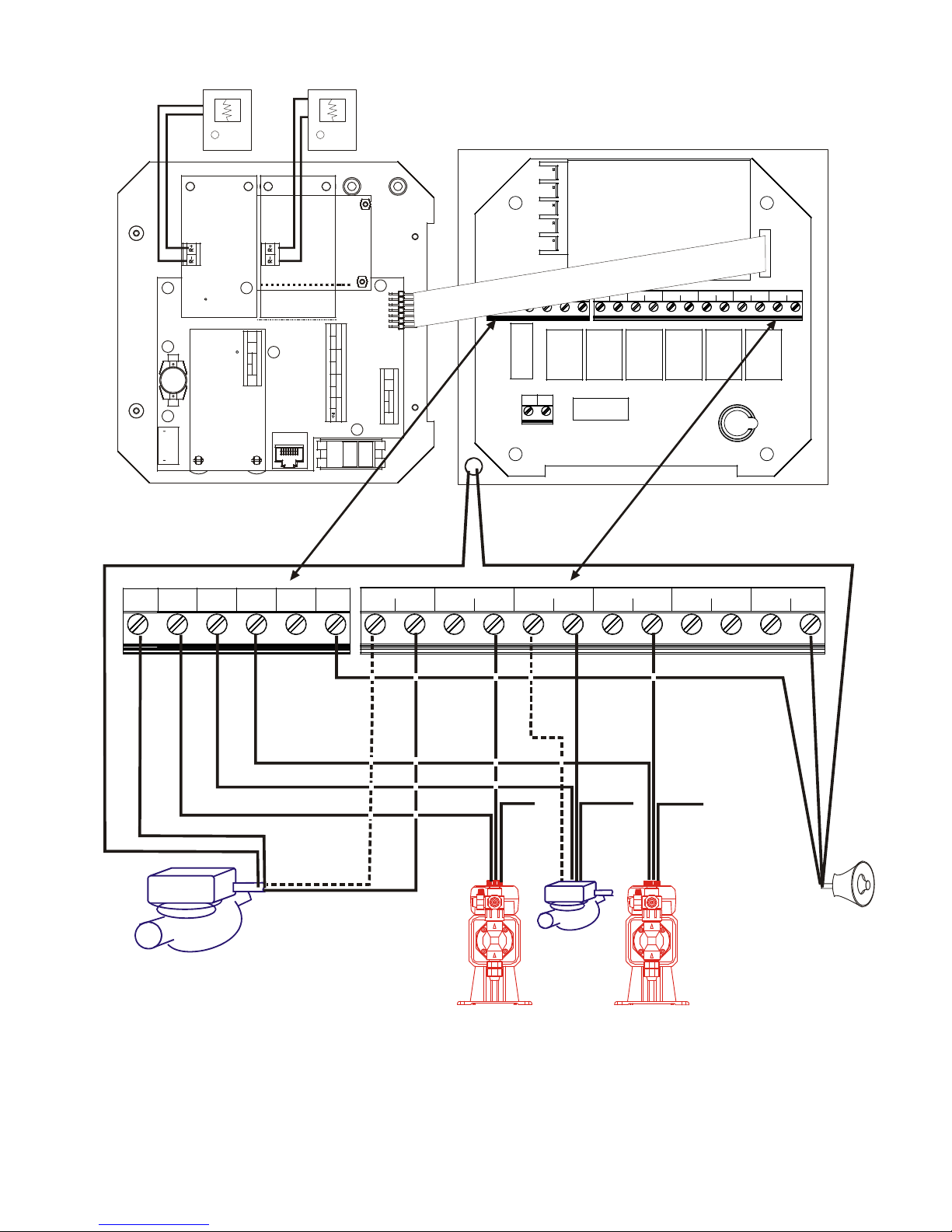
BLEED FEE D BOI 1 BIO 2 ALARM
N.C. N.O. N.C. N.O. N.C. N.O. N.C. N.O. N.C. N.O. N.C. N.O.
GROUND
STUD
BLK 120V
BLEED B
BRN 240V
IF MOTORIZED
WHT 120V
BLU 240V
BLK 120V
BALL VALVE
BRN 240V
BLK 120V
BRN 240V
BLEED A FEED A FEED B ALARM
N.C. N.O. N.C. N.O. N.C. N.O. N.C. N.O. N.C. N.O.
BLK 120V
BRN 240V
GRN 120V
GRN/YEL 240V
BLK 120V
BRN 240V
IF MOTORIZED
BALL VALVE
NOTE: When connecting a
motorized ball valve, the pre-wired
pigtail must be removed and the
valve requires two wires, one to
N.O. to open the valve and one to
Bleed Solenoid/
N.C. to close the valve.
Motorized Ball Valve
GRN 120V
GRN/YEL 24 0V
TO GROUND
STUD
Solenoid/
Motorized
Ball Valve
Pum
Figure 4 Outputs
9
Bleed
GRN 120V
GRN/YEL 240V
TO GROUND
STUD
Pum
GRN 120V
GRN/YEL 240V
TO GROUND
STUD
larm
 Loading...