

Walchem WDS600, WDS410, WDS900, WDS100 Instruction Manual

Five Boynton Road Hopping Brook Park Holliston, MA 01746 USA
Disinfection Sensors
W A L C H E M
IWA KI Am eri ca Inc .
Non-Membrane Disinfection Sensors
Instruction Manual
TEL: 508-429-1110 WEB: www.walchem.com

Notice
© 2019 WALCHEM, Iwaki America Inc. (hereinafter “Walchem”) Five Boynton Road, Holliston, MA 01746 USA (508) 429-1110 All Rights Reserved Printed in USA
Proprietary Material
The information and descriptions contained herein are the property of
WALCHEM. Such information and descriptions may not be copied or
reproduced by any means, or disseminated or distributed without the
express prior written permission of WALCHEM, Five Boynton Road,
Holliston, MA 01746.
Statement of Limited Warranty
WALCHEM warrants equipment of its manufacture, and bearing its identification
to be free from defects in workmanship and material for a period of 24 months
for electronics and 12 months for mechanical parts and electrodes from date of
delivery from the factory or authorized distributor under normal use and service
and otherwise when such equipment is used in accordance with instructions
furnished by WALCHEM and for the purposes disclosed in writing at the time of
purchase, if any. WALCHEM’s liability under this warranty shall be limited to
replacement or repair, F.O.B. Holliston, MA U.S.A. of any defective equipment
or part which, having been returned to WALCHEM, transportation charges
prepaid, has been inspected and determined by WALCHEM to be defective.
Replacement elastomeric parts and glass components are expendable and are not
covered by any warranty.
THIS WARRANTY IS IN LIEU OF ANY OTHER WARRANTY, EITHER
EXPRESS OR IMPLIED, AS TO DESCRIPTION, QUALITY,
MERCHANTABILITY, and FITNESS FOR ANY PARTICULAR PURPOSE OR
USE, OR ANY OTHER MATTER.
P/N 180560.G
June 2019

Table of Contents
1.0
Introduction ....................................................... 1
Sensor 1
Flow Cell 1
2.0 Installation ......................................................... 2
Assembling the Sensor 2
Flow Cell Placement 4
Installing Sensor into Flow Cell 4
Sensor Parts 5
Typical Installation 5
Optional Flow Switch Installation 7
Wiring Instructions 7
3.0 Operation ......................................................... 14
Conditioning 14
Calibration 14
4.0 Troubleshooting ............................................. 16
The disinfectant reading is much lower than the manual
analysis 16
The disinfectant reading is much higher than the manual
analysis 16
Sensor Error 17
Disinfectant Reading is Unstable 17
Calibration Failure 18
5.0 Maintenance .................................................... 19
Cleaning the Electrodes 19
Sensor Storage 19
6.0 Specifications ................................................. 21
7.0 Sensor Part Numbers ..................................... 22

1.0 Introduction
The Walchem non-membrane chlorine and chlorine dioxide sensors
consist of an amperometric sensor assembly, cable and a flow cell.
Assembly of these parts is required, so please read these instructions
carefully. The sensor is capable of measuring the disinfectant in drinking
water or drinking water quality water.
Sensor
The sensor assembly includes the sensor body, a 50-ml bottle of electrolyte
fill solution, and special abrasive emery paper. Make sure that all parts are
included.
The sensors are open (not-membrane covered) amperometric 3-electrode
types. The measuring and counter electrode are in direct contact with the
measuring water. The reference electrode is separated from the measuring
water by a housing which contains an electrolyte. Together with the
electrolyte, an electrical signal is generated at the measuring electrode
which is proportional to the concentration of the disinfectant, and
amplified by the electronics of the sensor. The measuring signal is
temperature compensated.
Flow Cell
The flow cell consists of a translucent flow cell body, mounting nut and oring, washer set and o-ring. Make sure that all parts are included.
The flow cell is required. The sensor will not read accurately if it is not
installed in the flow cell, with a steady flow rate between 20 and 100 liters
per hour, at an operating pressure of 8 atmospheres or less.
1
2.0 Installation
Assembling the Sensor
CAUTION: Wear gloves and safety glasses during assembly of
the sensor since the electrolyte is a diluted acid. It is recommended
to perform this operation over a sink with running water available.
Please heed the warnings on the electrolyte bottle. Do not swallow
the electrolyte. Avoid contact of the electrolyte with skin and eyes.
Otherwise wash with a lot of water. In case of eye inflammation,
contact a doctor.
After using, re-cap any remaining electrolyte and store the bottle
upside-down until the next use.
Never shake the electrolyte bottle, as this will introduce air bubbles
that will negatively impact performance!
Do not touch or otherwise contaminate the electrodes!
For PEEK sensors, never remove the reservoir cartridge
attached to the reference electrode!
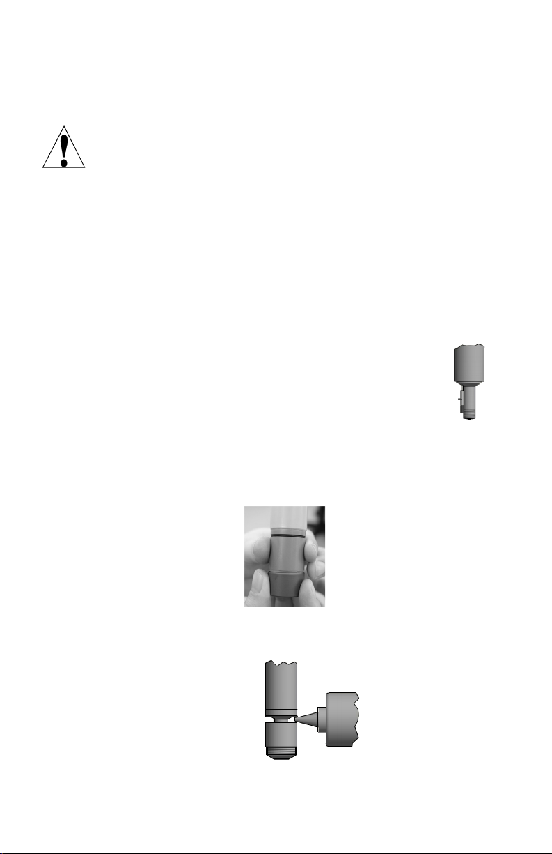
Sensors without optional cleaning attachment
1. Holding the sensor at the housing as shown, unscrew the dark grey
protective cap. The cap contains liquid. Save the protective cap in
case the electrode will need to be stored for more than a month of
downtime.
2. Unscrew the housing until there is a gap, then fill it to the top with
the electrolyte until it overflows. Never shake the electrolyte
bottle, it must stay free of bubbles!
2
3. SLOWLY screw on the housing until it is hand tight. Be prepared
for some electrolyte solution to squeeze out.
4. Rinse your hands, the sensor, and all surfaces contaminated with
electrolyte solution with running water. Check the sensor for leaks.
5. Push the cable onto the end of the sensor, aligning the pins with the
holes. Turn the connector until hand tight to seal the cable
connection.
Sensors with optional cleaning attachment
The cleaning attachment consists of a cleaning chamber and two
bags of glass balls. When using the cleaning attachment, the
minimum sample flow rate is 45 l/hour! The cleaning attachment
is only effective in removing thin deposits.
1. Complete the steps above for sensors without cleaning attachment.
2. Remove the o-ring holder from the acrylic flow cell and slide it up
onto the sensor to sit below the o-ring.
3. Place three of the glass balls into the cleaning chamber and screw
it onto the electrolyte housing.
3

Flow Cell Placement
Instructions for mounting the sensor into the process can vary greatly with
the circumstances that are encountered in your application. Here are some
general guidelines to assist you. Refer also to the typical installation
drawings.
The flow cell should be placed on the discharge side of a circulation pump
or downhill from a gravity feed. Flow into the cell must come from the
bottom side that has the 8 mm OD tubing x ¼” straight thread fitting
installed.
The outlet of the flow cell must be plumbed to open atmosphere unless the
system pressure is at or below 8 atmospheres. If the flow through the line
cannot be stopped to allow for cleaning and calibration of the sensor, then it
should be placed in a by-pass line with isolation valves to allow for sensor
removal. Install the sensor vertically, with the measuring surface pointing
down, at least 5 degrees above horizontal. (Refer to Installation drawing)
Flow rate regulation must be done upstream from the sensor, because any
flow restriction downstream can increase the pressure above the rated value.
The acrylic flow cell has a flow regulator knob on the lower left hand side.
The sensor should be installed in an area where there is good solution
movement and where it will respond rapidly to chemical additions. The
placement of the sensor relative to the placement of chemical
replenishment, along with the quality of the mixing, and the replenishment
chemical flow rate are critical to accurate process control.
To avoid biological growth on the electrodes, which can block
measurement, never leave the sensor in water without oxidant for longer
than 24 hours, unless using the optional cleaning attachment.
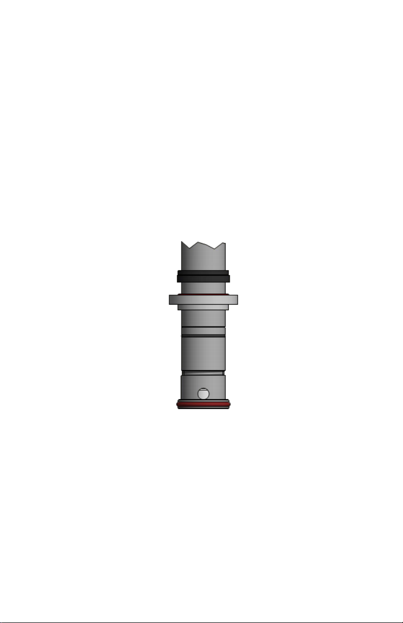
Installing Sensor into Flow Cell
1. For sensors without the cleaning attachment, unscrew the 1 ¼” fitting
from the acrylic flow cell. Insert the sensor as shown below.
Push the 1 ¼” fitting over the sensor and fasten it tightly. Make sure that
the sensor is tightly fastened in place, otherwise it may be pushed out of
the flow cell when it is under pressure, or leaks can occur.
2. For sensors with the cleaning attachment, unscrew the 1 ¼” fitting from
the acrylic flow cell. Insert the sensor with mounted cleaning attachment
and o-ring holder into the flow cell by turning it CLOCKWISE until the
o-ring holder is snug (turning CCW can loosen the electrolyte housing
4
and/or cleaning attachment). Make sure that the large black o-ring is
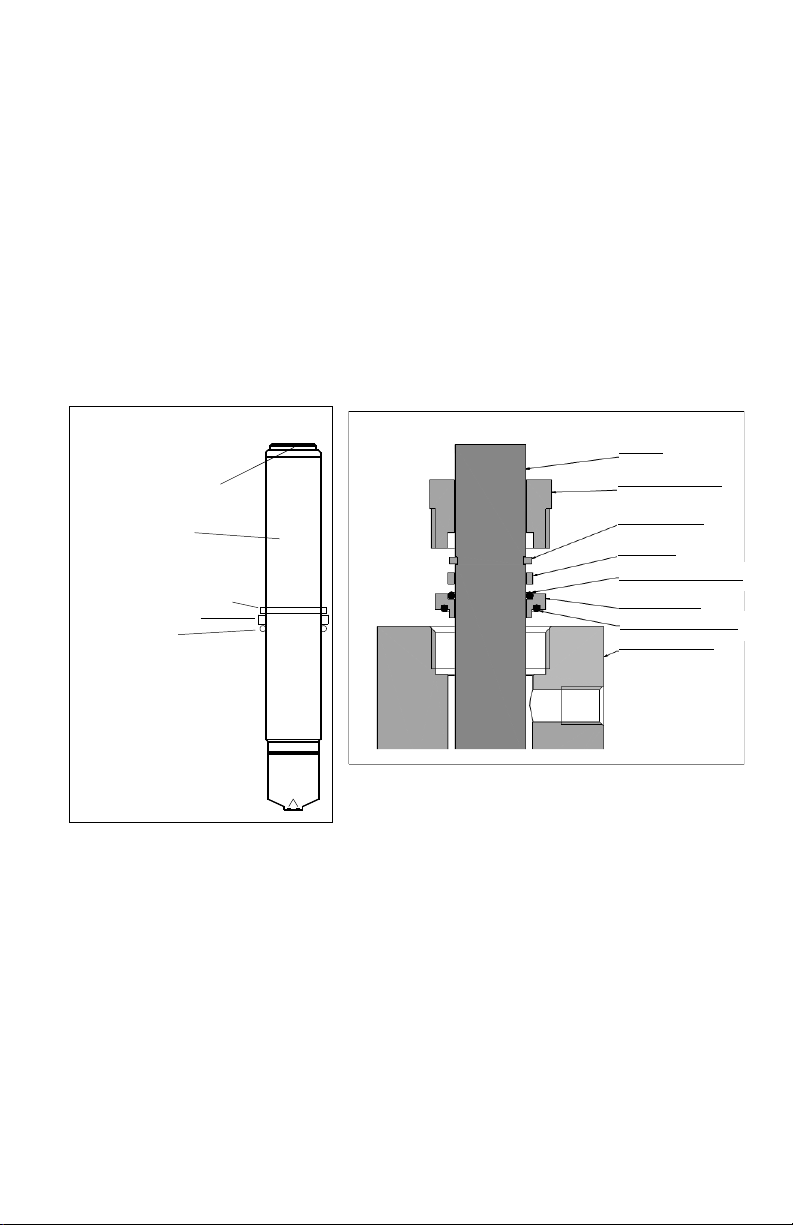
O ring
connector
electrode
shaft with
amplifier
retaining ring
slide ring
Sensor
Screw fitting 1¼”
Retaining ring
Slide ring
O-ring holder
O-ring 20 x 2.6 (Viton)
Acrylic flow cell
O-ring 25 x 2.5 (silicon)
located between the o-ring holder and the flow cell, as shown below.
Push the 1 ¼” fitting over the sensor and fasten it tightly. Make sure that
the sensor is tightly fastened in place, otherwise it may be pushed out of
the flow cell when it is under pressure, or leaks can occur.
3. To supply a sample, first open the water outlet valve. Then open slowly
the measuring water supply valve. The minimum flow rate is 45
liters/hour when using the cleaning attachment, 20 liters/hour without.
The acrylic flow cell has a flow regulator knob on the lower left hand
side. Avoid installations that allow air bubbles to enter the measuring
water.
Sensor Parts
5
 Loading...