

Page 1

WCU Series
Electroless Copper Controller
Instruction Manual
Page 2

Notice
©2006 WALCHEM Corporation
5 Boynton Road, Holliston, MA 01746 USA
(508) 429-1110
All Rights Reserved
Printed in USA
Proprietary Material
The information and descriptions contained herein are the property of WALCHEM
Corporation. Such information and descriptions may not be copied or reproduced by any
means, or disseminated or distributed without the express prior written permission of
WALCHEM Corporation, 5 Boynton Road, Holliston, MA 01746.
This document is for information purposes only and is subject to change without notice.
Statement of Limited Warranty
WALCHEM Corporation warrants equipment of its manufacture, and bearing its
identification to be free from defects in workmanship and material for a period of 24
months for electronics and 12 months for mechanical parts from date of delivery from the
factory or authorized distributor under normal use and service and otherwise when such
equipment is used in accordance with instructions furnished by WALCHEM Corporation
and for the purposes disclosed in writing at the time of purchase, if any. WALCHEM
Corporation's liability under this warranty shall be limited to replacement or repair, F.O.B.
Holliston, MA U.S.A. of any defective equipment or part which, having been returned to
WALCHEM Corporation, transportation charges prepaid, has been inspected and
determined by WALCHEM Corporation to be defective. Replaceable elastomeric parts and
glass components are expendable and are not covered by any warranty.
THIS WARRANTY IS IN LIEU OF ANY OTHER WARRANTY, EITHER EXPRESS OR
IMPLIED, AS TO DESCRIPTION, QUALITY, MERCHANTABILITY, FITNESS FOR ANY
PARTICULAR PURPOSE OR USE, OR ANY OTHER MATTER.
P/N 180099.J1
Feb 2006
Page 3

TABLE OF CONTENTS
1.0 Introduction.............................................................................................................1
2.0 Specifications .........................................................................................................1
2.2 Electrical: Input/Output..........................................................................................1
2.3 Mechanical............................................................................................................2
3.0 Unpacking and Installation....................................................................................2
3.1 Unpacking the unit ................................................................................................2
3.2 Mounting the electronic enclosure ........................................................................3
3.3 Immersible Copper Sensor Installation .................................................................3
3.4 Flow Through Copper Sensor/Sample Loop Installation.......................................4
3.5 Control Module Installation....................................................................................8
3.6 Icon Definitions .....................................................................................................9
3.7 Electrical Installation .............................................................................................9
4.0 Function Overview ...............................................................................................14
4.1 Front Panel .........................................................................................................15
4.2 Display ................................................................................................................15
4.3 Keypad................................................................................................................16
4.4 Access Code.......................................................................................................16
4.5 Startup ................................................................................................................16
4.6 Shutdown............................................................................................................17
5.0 Operation...............................................................................................................17
5.1 Main Menu ..........................................................................................................17
5.2 Sensor Menu.......................................................................................................18
5.3 Output 1 Menu ...................................................................................................22
5.4 Output 2, 3, and 4 Menus....................................................................................26
5.5 Clock Menu .........................................................................................................27
5.6 Alarm Menu.........................................................................................................28
5.7 4-20 mA Menu (Optional)....................................................................................28
5.8 Access Code Menu.............................................................................................29
6.0 Maintenance..........................................................................................................31
6.1 Sensor Maintenance ...........................................................................................31
6.2 Replacing the Fuses ...........................................................................................31
7.0 Troubleshooting ...................................................................................................32
7.1 Error Messages...................................................................................................32
8.0 Service Policy .......................................................................................................35
Page 4
1.0 Introduction
The WCU310 series copper controllers are optoelectronic on-line analyzers that may
be used in variety of applications including electroless copper baths, microetch baths
and a number of other chemistries that contain more than 0.10 grams/liter (g/L) of
copper ions.
There are four relays that may be used as control outputs that are activated
simultaneously. The direction of control is selected via software. The outputs each
have timers associated with them, that may be used to track the volume of chemistry
added, or the time that the output has been on.
An optional 4-20 mA output that is proportional to the copper concentration is
available.
Either an immersible in-tank sensor or flow-through out-of-tank sensor may be
specified.
2.0 Specifications
2.1 Measurement Performance
Electroless Copper Concentration Range: .01 - 5.5 g/L (.001 - 0.73 oz/gal)
Microetch Copper Concentration Range: .01 - 99 g/L (.001 – 13.2 oz/gal)
Concentration Resolution: .001 g/L (.0001 oz/gal)
Concentration Accuracy: .01 g/L (.001 oz/gal)
2.2 Electrical: Input/Output
Input Power
110-120 VAC or 220-240 VAC
50/60 Hz, 10A 50/60 Hz, 5A
Input Signals
Sensor Power: + 5VDC, 150 mA
Signals: 0 to 2VDC
Interlock (optional) Isolated dry contact closure required (i.e., flow,
level, etc.)
Output
Mechanical Relays (5) @ 120 VAC, 10A resistive, 1/8 HP
@ 240 VAC, 5A resistive, 1/8 HP
internally powered, switching line voltage
4 - 20 mA (optional) Fully isolated, internally powered 600 Ω max.
resistive load. Resolution .001% of span, accuracy
± 1% of reading.
1
Page 5

Agency Approvals
UL UL 61010-1, 2
CSA C22,2 No.61010-1 2nd Edition
CE Safety EN 61010-1 2
CE EMC EN 61326 :1998 Annex A*
Note: For EN61000-4-6,3 the controller met performance criteria B.
*Class A equipment: Equipment suitable for use in establishments other than
domestic, and those directly connected to a low voltage (100-240 VAC) power
supply network which supplies buildings used for domestic purposes.
2.3 Mechanical
Controller
Enclosure: Fiberglass
NEMA Rating: NEMA 4X
Dimensions: 8.5" x 6.5" x 5.5"
Display: 2 x 16 character backlit liquid crystal
Operating Ambient Temp: 32 - 122°F (0 - 50°C)
Storage Temperature: -20 to 180°F (-29 to 80°C)
Shipping Weight: 7 lbs (3kg) (approximately)
Sensor
Immersible Flow Through
Enclosure: Polycarbonate/Polypro ABS
NEMA Rating: NEMA 4X NEMA 4X
Dimensions: 5.25" x 4.0" x 20.25" 6.75" x 4.75" x 2.25"
Operating Ambient Temp: 32 - 122°F (0 - 50°C) 32 - 122°F (0 - 50°C)
Storage Temperature: -40 to 185°F (-40 to 85°C) -40 to 185°F (-40 to 85°C)
Solution Temperature: 200°F (93°C) max. 200°F (93°C) max.
Maximum cable length: 80 ft . 80 ft.
nd
Edition
nd
Edition
3.0 Unpacking and Installation
3.1 Unpacking the unit
Inspect the contents of the carton. Please notify the carrier immediately if there are
any signs of damage to the controller or its parts. Contact your distributor if any of
the parts are missing. The carton should contain a WCU310 controller and
instruction manual. Any options or accessories will be incorporated as ordered.
2
Page 6

3.2 Mounting the electronic enclosure
The WCU series controller is supplied with mounting holes on the enclosure. It
should be wall mounted with the display at eye level, on a vibration-free surface,
utilizing all 4 mounting holes for maximum stability. Use M6 (1/4" diameter)
fasteners that are appropriate for the substrate material of the wall. The enclosure is
NEMA 4X rated. The maximum operating ambient temperature is 122° F (50° C).
The enclosure requires the following clearances:
Top: 2"
Left: 8"
Right: 4"
Bottom: 7"
3.3 Immersible Copper Sensor Installation
The immersible copper sensor is designed for direct in-tank monitoring of
electroless copper and microetch solutions. By monitoring the copper content
directly in the solution, control lag and hydraulic problems are eliminated.
The sensor is constructed such that a constant path length exists between the fiber
optic light guides. The solution between the light guides absorbs light at specific
wavelengths in proportion to the copper concentration. The lamp and electronics are
located under the cover of the sensor. In order to avoid a shift in calibration due to
condensation, the sensor's cover should NEVER be opened.
The immersible sensor is provided with a mounting plate and 20 feet of cable.
Extension cable is available if the sensor can not be mounted within 20 feet of the
controller. The maximum cable length is 80 feet.
While the positioning of the sensor is not particularly sensitive to the tank layout,
the following suggestions are given to aid installation:
Do not place the sensor beside heaters; if solution flow stops, the polypropylene
guard may melt.
Do not immerse the entire sensor, or the cable.
Place the sensor where the loads of parts will not strike it.
Place the sensor in an area of good solution movement, but not directly in the
path of any air agitation.
Mount the sensor securely to the rim of the tank using the holes provided. If the
tank is rimless, use a block to provide the support for the mounting plate.
Attach the cable's connector to the WCU controller. The connector is keyed, do not
force! The sensor you receive with the controller has already been calibrated.
3
Page 7

3.4 Flow Through Copper Sensor/Sample Loop Installation
The copper flow through sensor is designed for out-of-tank monitoring of electroless
copper and microetch solutions.
The sensor is designed with a glass tube that contains the copper solution that forms
a fixed path length between the lamp and receptor module. The solution absorbs
light at specific wavelengths in proportion to the copper concentration. In order to
avoid a shift in calibration caused by condensation, the sensor cover should NEVER
be removed!
The flow through sensor is provided with a mounting plate and 20 feet of cable.
Extension cable is available if the sensor can not be placed within 20 feet of the
controller. The maximum cable length is 80 feet.
The sample loop consists of a shut off valve, a cooling coil or plate, a sensor and a
pump or any combination thereof. The shut off valve is to quickly isolate the system
if necessary. A cooling coil or plate is necessary to cool the copper solution down to
a temperature acceptable to a sample pump. Cooling the solution is also
recommended to help reduce the amount of plate out which may form in the sample
loop. The pump may be either a stand alone sample pump (which typically have
temperature restriction) or a high temperature pump (which is usually just a branch
off the recirculation pump).
4
Page 8
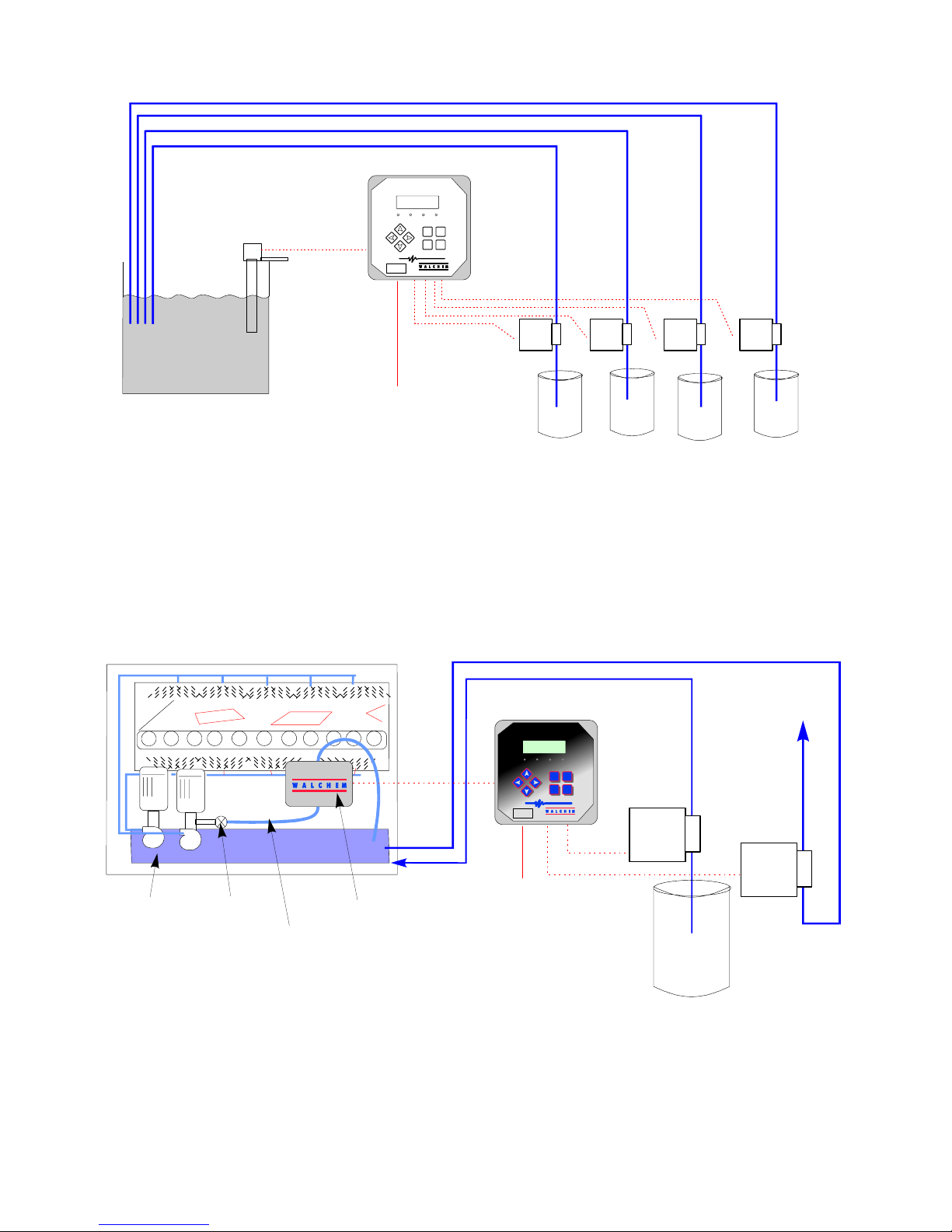
IMMERSIBLE
SENSOR
PLATING BATH
(TYPICAL ELECTROLESS COPPER APPLICATION)
CONVEYORIZED SPRAY EQUIPMENT
CIRCULATING
PUMPS
MANUAL
VALV E
3/8" TUBING
(< 20' PERFERRABLE)
WCU with Immersible Sensor
COPPER CONTR OLLER
CU
OUT 3OUT 2 OUT 4
20 FT
(80 FT MAX.)
POWER
WCU WITH IMMERSIBLE SENSOR
NEXTPREV.
EXIT ENTER
WCU MICROETCH CONTROLLER
COPPER CONTROLLER
CU
80 FT. MAX.
POWER
FLOW
THROUGH
SENSOR
WCU WITH FLOW-THROUGH SENSOR
(TYPICAL MICROETCH APPLICATION)
WCU310 Series Copper Controller
Figure 1 Typical Installation
COPPER
OUT 3OUT 2 O UT 4
NEXTPREV.
EXIT ENTER
CAUSTIC
FORMALDEHYDE
METERING PUMPS
SODIUM
PERSULFATE
STABILIZER
TO
WASTE
TREATMENT
"BLEED"
5
Page 9

The flow through sensor/sample loop must be installed according to the following
guidelines:
Mount the sensor on a vibration-free, vertical surface so that the sensor tubing
inlet connection is at the bottom and the outlet is at the top. The vertical
orientation will prevent air bubbles from being trapped in the sensor.
Install a shut-off valve at the beginning of the sample loop so that the system
may be shut off quickly if necessary.
If a sample pump is to be used, it must be installed last, after the flow through
sensor and the cooling coil or plate, if applicable.
Other installation guidelines which may be helpful in the overall system:
Mount the sensor as close to solution as possible. Keep tubing distances to the
sensor inlet as short as possible to avoid hydraulic lag time. Maximum
recommended length of tubing from solution to sensor is 25 feet. If this is not
possible, see Application Notes below.
The solution inlet should draw sample from an area of good solution movement
in order to respond quickly to chemical additions. However, the solution inlet
should not draw too near to where the chemistry is added to avoid artificial
'spikes' in concentration.
The solution discharge should be open to atmospheric pressure in order to ensure
proper flow.
The cable connector to the controller is keyed, do not force!
6
Page 10

Application Notes
If the distance from the solution to the sensor is further than the recommended
length of 25 feet, the maximum lagtime must be calculated from the desired control
band to determine a pump flow rate based on a given distance of standard, uniform
tubing. The maximum lagtime is the maximum allowable time for the solution to
continuously get to the sensor in order to achieve the desired control band.
To calculate maximum lagtime:
Max. Lagtime = Desired Control Band*
4 x Depletion Rate
For Example: The set point is 4.00 g/L.
then Max. Lagtime = 0.20 g/L
4 x (0.08333 g/L /min)
So, 0.60 minutes is the maximum time it should take for the solution to reach the
sensor.
To calculate pump flow rate:
Minimum Pump Flow Rate = Volume of System*
Maximum Lagtime
where Volume of system = ( Tubing I.D.)2 x Length of tubing
2
Maximum lagtime = Previously calculated time to get solution to
sensor.
* Volume is based on length from solution to sensor, not the return.
For Example: If the system parameters are: Tubing is 3/8" O.D. x 1/4" I.D.
Length is 30 feet (360 inches)
then the volume of the system = ( 0.25 in )2 x (360 in) = 17.7 in3
2
where Control band = Maximum deviation of concentration
Depletion rate = Rate at which the bath will deplete per unit
of time
* The deadband should be adjusted so that it is 1/4 the desired control
band.
If the desired control band is 0.20 g/L (± 0.10 g/L or 2.5%) and the bath is
depleting at a rate of 1.25 g/L every 15 minutes (0.08333 g/L every minute),
= 0.60 minutes
7
Page 11

Note: 1 U.S. Gallon = 231 U.S cubic
inches
1 Liter = 61.03 U.S. cubic inches
Volume of Cooling Coil: 0.018 Gallons
0.068 Liters
Volume of Cooling Plate: 0.023 Gallons
0.088 Liters
Volume of 3/8" O.D. x 1/4" I.D. (0.59 in3/ft): 0.00255 Gallons/linear ft
0.00965 Liters/linear ft
Volume of the system = 17.7 in3 = 0.0765 gallons
231 in3 / gallon
Maximum lagtime = 0.60 minutes (previously calculated)
So, the minimum pump flow rate
= 0.0765 gallons
0.60 minutes
= 0.127 gal/min (483 mL/min)
Caution: The calculated pump flow rate is the minimum required to obtain the
desired control band, however, if the flow rate increases over the recommended rate
of 500 mL/min (approx. 0.13 gal/min) the rate of cooling will decrease. This may be
compensated for by re-evaluating the system criteria: length / desired control band
or to double up on the cooling plate/coil.
Consult factory with any further installation questions.
3.5 Control Module Installation
Once the enclosure is mounted, the output pumps may be located at any distance
from the controller. The sensor may be placed up to 80 feet from the controller.
Shielded cable is preferable. Always route AC voltage wiring in conduit that is
separated a minimum of 6 inches away from low voltage DC signal lines (such as
the sensor signal).
8
Page 12
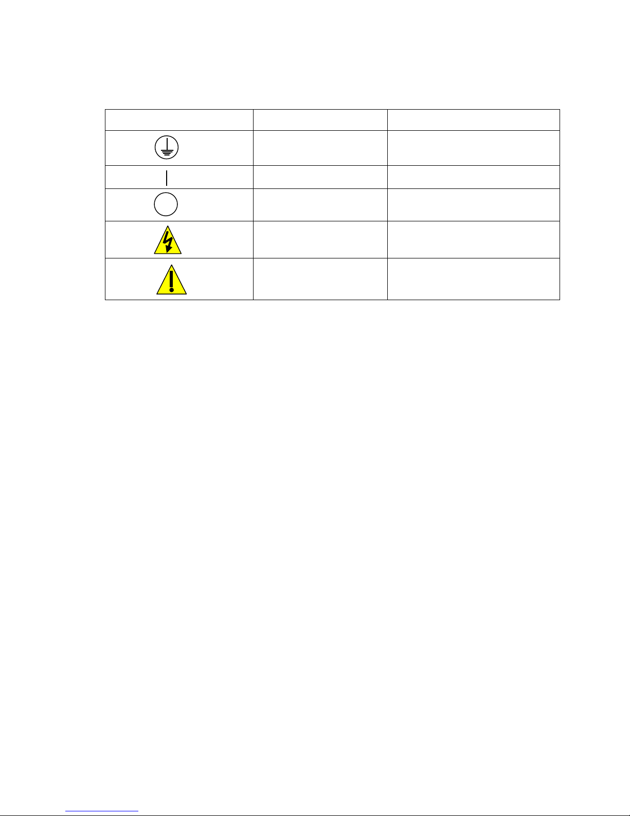
3.6 Icon Definitions
Symbol Publication Description
IEC 417, No. 5008 Off (Supply)
3.7 Electrical Installation
Based on the model number, the following voltages are required:
WCU310-1xx 120 VAC, 50/60 Hz
WCU310-4xx 120 VAC, 50/60 Hz
WCU310-5xx 240 VAC, 50/60 Hz
The various standard wiring options are shown below. Your WCU series controller
will arrive from the factory prewired or ready for hardwiring. Depending on your
configuration of controller options, you may be required to hardwire some or all of
the input/output devices. Refer to figures 3 and 4 for circuit board layout and wiring.
Note: When wiring the optional 4-20 mA output or a remote flow switch, it is
advisable to use stranded, shielded, twisted pair wire between 22-26 AWG. Shield
should be terminated at the controller ground stud (see figure 4).
IEC 417, No.5019
Protective Conductor
Terminal
IEC 417, No. 5007 On (Supply)
ISO 3864, No. B.3.6 Caution, risk of electric shock
ISO 3864, No. B.3.1 Caution
9
Page 13

CAUTION! There are live circuits inside the controller even when the power
switch on the front panel is in the OFF position! The front panel must never be
opened before power to the controller is REMOVED!
If your controller is prewired, it is supplied with a 8 foot, 18 AWG power cord with
USA style plug. A tool (#1 phillips driver) is required to open the front panel.
CAUTION! When mounting the controller, make sure there is clear access to the
disconnecting device!
CAUTION! The electrical installation of the controller must be done by trained
personnel only and conform to all applicable National, State and Local codes!
CAUTION! Proper grounding of this product is required. Any attempt to bypass
the grounding will compromise the safety of persons and property.
CAUTION! Operating this product in a manner not specified by Walchem may
impair the protection provided by the equipment.
Optional Input
Hardwired Option WCU310
4-20 mA Output Optional Optional Sensor
(optional) Input Input Connector
Strain reliefs (230 VAC) or Holes for
Hardwiring of Input Power and Control Outputs
Side View
Optional
Input
WCU310 Prewired Option
4-20 mA (optional)
Sensor
Connector
Bottom View
Outputs
Inputs
Bottom View
Alarm Output 3 Output 4
Power Output 2 Cu
Supply Output
Figure 2 Conduit/Wiring Configuration
10
Page 14

Figure 3 Inputs (for power relay board #191236)
11
Page 15

4-20mA
_
+
(Optional 4-20 mA Board)
F1
F2
To Grounding
Stud
White
w/Green Stripe
Green
(INPUTS - ALL MODELS)
COM
White
w/Blue
Stripe
Blue
Orange
(Grounding
Stud)
FLOW
VM
SWITCH
NEU
GRN (115V)
GRN/YEL (230 V)
WHT (115V) BLU (230V)
FM
(Polarity
not
critical)
HOT
190873
BLK (115V)
BRN (230V)
TB2
TB3
NEUTRAL
Panel Mount
Connector
Figure 3a Inputs (for power relay board #190873)
Flow or Level
Switch
12
Power Supply
(115 VAC or 230 VAC)
Page 16

Note: The Alarm Rel ay is non-programmable.
Refer to the Main Menu diagram on page 16
for the list of error conditions that trigger the
alarm relay.
Figure 4 Outputs (for power relay board #191236)
Note: All relay outputs are
internally powered switching
line voltage.
13
Page 17

A
Chart
Recorder
4-20mA
_
+
(Optional 4-20 mA Board)
F1
F2
TB2
TB3
(Grounding
Stud)
OUTPUTS
OUT3
OUT4
LRM
N.O.
K
L
GRN
GRN
GRN
B
N.O.
N.O.
OUT2
N.O.
BLK
NEU
HOT
OUT1
N.C. N .O.
190873
BLK
NEUTRAL
WHT
WHT
WHT
WHT
Alarm
GRN
Pump(s)
GRN
Figure 4a Outputs (for power relay board #190873)
14
WHT
Page 18

4.0 Function Overview
4.1 Front Panel
Backlit LCD Display
Output LEDs
Setting Adjustment Keys
Menu/Function Keys
COP PER CO NTR OLLER
CU
OUT 3OUT 2 OUT 4
EXIT
NEXTPREV.
ENTER
On/Off Power Switch
4.2 Display
A summary screen is displayed while the WCU controller is on. This display shows
a bar graph of the copper concentration relative to the set point, a digital display of
the copper concentration, and the current operating conditions.
Towards the center of the bar graph is an (S), which represents the set point. For
each 1% rise above the set point a vertical line appears to the right of the (S). For
each 1% drop below the set point a vertical bar appears to the left of the (S). There
are small breaks in the bars at each 5%. If high or low alarm limits are reached, then
either an (H) or (L) will appear.
The operating conditions which may be displayed on the bottom line of the display
are: Control Delay 30* (number counts down), Sensor Error, Light Bulb Out, No
Sample, Plate Out, Manual Output* Interlock, Output Disabled*, Pump Overrun,
High/Low Alarm, Turnover Limit, Calibration Time, Outputs On* and Normal*
*These messages do not activate the diagnostic alarm relay.
Front Panel
Summary Display
15
Page 19

4.3 Keypad
The keypad consists of 4 directional arrows and 4 function keys. The arrow keys are
used to move the adjustment cursor and change settings, while the function keys are
used to enter values, and navigate the various menu screens. The function keys are
ENTER, EXIT, NEXT and PREV (previous). NEXT and PREV scroll through the
various menu choices. ENTER is used to enter a menu and to enter a value. EXIT is
used to back up one menu level. If you are at the main menu level, EXIT will return
you to the summary screen.
To change a value or option in a submenu, the left/right arrow keys move the cursor
left and right to each digit or option that can be changed. The up/down arrows will
change numeric values up or down, or scroll through option choices. Press ENTER
only when you have finished making ALL of the changes for that menu screen.
4.4 Access Code
The WCU series controller is shipped with the access code disabled. If you wish to
enable it, see Section 5.8 for operation. With the access code enabled, any user can
view parameter settings, but not change them. Note that this provides protection
only against casual tampering. Use a lock on the cover latch if you need more
protection.
4.5 Startup
Initial Startup
After having mounted the enclosure and wired the unit, the controller is ready to use.
CONTROL DELAY: The display will show the WCU series model number then
revert to the top level summary screen with "Control Delay" for a status message. This
message will be displayed for approximately 30 seconds. In some situations, the user
may not want the unit to be controlling and possibly turning on pumps when it is first
powered on. This allows you enough time to enter the Output menus and disable the
outputs. The only difference in the controller operation during these 30 seconds is that
it will not activate any outputs. All measurements are live and all menus are
accessible. Scroll through the menus, calibrate the sensor, and set the control
parameters as detailed in Section 5, Operation.
16
Page 20

To return to the summary screen, press the EXIT key until you return to this screen.
The controller will automatically return to this screen after 10 minutes.
Normal Startup
Startup is a simple process once your set points are in memory. Simply check your
supply of chemicals, turn on the controller, calibrate the sensor if necessary and it
will start controlling.
4.6 Shutdown
To shut the WCU controller down, simply turn off the power switch. Programming
remains in memory.
5.0 Operation
These units control continuously while power is applied. Programming is
accomplished via the local keypad and display.
To view the top level menu, press any key. The menu structure is grouped by inputs
and outputs. Each input has its own setup menu for calibration and unit of measure
selection as needed. Each output has its own setup menu including set points, timer
values, direction of control, etc as needed. After 10 minutes of inactivity in the
menu, the display will return to the summary screen. Keep in mind that even while
browsing through the menus, the unit is still controlling.
5.1 Main Menu
The exact configuration of your WCU controller determines which menus are
available as you scroll through the settings. Certain menus are only available if you
select certain options. All settings are grouped under the following main menu
items:
Sensor
Out 1
Out 2
Out 3
Out 4
Alarm
Time
4-20 mA (Only if 4-20 mA option circuit board is installed)
Access Code
The NEXT key travels forward through this list while the PREV key travels
backwards through the list. Pressing ENTER will enter the lower level menu that is
currently displayed.
17
Page 21

5.2 Sensor Menu
The sensor menu provides the following settings: Calibration history (informational
only), 1 point calibration, Days between Calibration, Units of measure, Control
mode, and New sensor set-up. Each is discussed in detail below. Refer to the Sensor
Menu Chart.
Note: If you are programming the unit for the first time, scroll to the Cu Mode menu
and set the "Cu Mode" option first, choosing either Electroless Copper or Microetch
mode. Then press PREV to choose units of measure. Then press NEXT to set the
rest of the menus.
Cal'd
Displays the date of the last sensor calibration.
1 Pt Calibration
Press ENTER to perform a 1 point calibration of the copper sensor. This calibration
is best performed at normal operating temperature.
Keep the immersible sensor in place or have solution flowing through the flow-
through sensor. Take a sample of the solution and note the concentration displayed
by the WCU controller. Carefully perform the normal laboratory analysis of the
copper concentration. Calculate the offset by subtracting the displayed value from
the lab results. If the lab analysis is significantly different, adjust the offset in the 1
point calibration menu, using the arrow keys to change the value and the +/- sign. If
the controller's display is higher than the lab analysis, the offset should be negative.
The maximum offset for a one point calibration is 7 g/l(0.7 oz/gal) from the last new
sensor setup value. If you have an offset larger than this, then perform a new sensor
setup (see next page).
Days Btwn Cal
Use the arrow keys to set the number of days that you would like to go by before
recalibrating the sensor. The controller will prompt you to recalibrate when that time
has expired. Setting this to zero days will disable the calibration reminder.
Conc. Units
Press ENTER to change the units of measure. Use the Up and Down arrows to
toggle between grams per liter and ounces per gallon, then press ENTER to make
your selection. The controller will warn you to check your set points, since all set
point values will stay the same even though the units of measure may have changed.
Cu Mode
Press ENTER to change the controller from Electroless copper mode to Microetch
mode by toggling between the two choices using the Up and Down arrow keys. The
controller will warn you to check your set points, since these do not change when
the Cu Mode is changed.
18
Page 22

S
S
Main Menu
OperationLegend
Press Enter key to enter menu or submenu.
Press Exit key to exit menu.
After 10 minutes of inactivity the controller will
Copper 1.98 g/L
Out 4 A 11:40
Copper 1.98 g/L
Access Code DIS
automatically return to the summary screen.
creens
tatus
Possible
* Control Delay 30
Sensor Error
Light Bulb Out
No Sample
Plate Out
* Manual Input
Interlock
* Output Disabled
Pump Overrun
1.98 g/L
S
NEXTPREV.
* These status screens DO NOT activate the diagnostic alarm relay
High/Low Alarm
Turnover Limit
Calibration Time
* Outputs On
* Normal
ENTEREXIT
NormalA
Copper 1.98 g/L
Out 3 A 11:40
Copper 1.98 g/L
4-20mA 12.4mA
Copper 1.98 g/L
Out 2 A 11:40
Copper 1.98 g/L
Time Thur 11:40
4-20mA menu is only present if
Copper 1.98 g/L
Out 1 A 11:40
Copper 1.98 g/L
Alarm
4-20mA option is installed.
Copper 1.98 g/L
Sensor
Main Menu
19
Page 23

Self Test
This feature is a diagnostic tool which can help isolate a problem between the sensor
and controller. Before initiating the self test, the sensor MUST be disconnected from
the controller in order to function properly. When ENTER is pressed the controller
disables the sensor inputs and injects 2 test signals, simulating a properly
functioning sensor. The controller will display "PASS" or "FAIL" along with a live
mV reading. If "PASS" is displayed then it indicates the controller is functioning
properly and the problem is likely to be with the sensor. See the troubleshooting
section for further details. If "FAIL" is indicated, the controller is defective. Consult
your factory representative for service options.
New Sensor Setup
Press ENTER to set up a new sensor. First you see a warning message:
"WARNING Chg sensor cal? N" This acts as a safety precaution for those who may
only be "browsing" through the menus. If you enter the New Sensor Setup menu,
you may easily, inadvertently, change the calibration of the sensor. If you continue
with the following procedures, you must recalibrate the new sensor.
Water....xxxx.x
Place the immersible sensor in clean tap or DI water, or circulate through the flow
through sensor. When the number on the display is constant, press ENTER.
Sample....xxxx.x
Place the sensor in the bath at a known concentration or restart pumping the bath
sample through the flow through sensor. No work should be going through the bath
so that the concentration remains constant. Ideally the bath should be at the typical
operating copper concentration. When the number on the display is constant, press
ENTER.
Smpl Conc
Use the arrow keys to change the displayed number to the actual concentration of
the bath in grams/liter or ounces/gallon, depending on the unit of measure you have
selected, then press ENTER.
mV in Display
This display is only for diagnostic purposes. The top line shows 2 live voltage
readings from the sensor in millivolts. The bottom line shows the stored values for
each sensor signal from the most recent new sensor set up calibration - specifically
the signal values measured with water.
20
Page 24

ENTER
EXIT
Sensor 1.98 g/L
mV in Display
ENTER
EXIT
Sensor 1.98 g/L
New Sensor Setup
m 300.4 r 232.1
*H 20 m 811.1 r234.6
New Sensor Setup
Water. . . 1230.8
New Sensor Setup
Sample. . . 30.2
New Sensor Setup
Chg Sensor Cal? N
. . . . WARNING . . . .
Smpl Conc 5.04
Sensor Menu
Operation
NEXTPREV.
Press Enter key to enter menu.
ENTER
Press Exit key to exit menu.
Blinking fields may be edited with the adjust arrows.
Press Enter when modification is complete to return
to Main Menu Level.
Sensor 1.98 g/L
Self Test
Sensor 1.98 g/L
Cu Mode E-Cu
Sensor 1.98 g/L
Days Btwn Cal 7
Sensor 1.98 g/L
Conc. Units g/L
ENTER
EXIT
Self Test PASS
m 611 r 202
ENTER
EXIT
Micro Etch
Cu Mode E-Cu
Electroless Cu
ENTER
EXIT
Conc. Units g/L
grams per Liter
Conc. Units g/L
ounces per Gal.
. . . . WARNING . . . .
. . . . WARNING . . . .
Check Set Points
Check Set Points
Sensor 1.98 g/L
1 Pt Calibration
ENTEREXIT
Copper 1.98 g/L
Sensor
Sensor 1.98 g/L
Cal'd Mar/10/96
EXIT
Adjust Offset
g/L + 0.10
Sensor Menu
21
Page 25

5.3 Output 1 Menu
The Out 1 menu is used to set the control set point, and to configure the
timer/totalizer to keep track of replenishment in the desired way. This menu
provides the following settings: Total 1, Set Point, Dead Band, Time Limit,
Interlock, and H O A.
The top level menu status line may display the following messages: Off, Intrlck,
Timeout, or a time. "Off" indicates that the output is off. "Intrlck" indicates that the
output would be on but is not because of a signal from a flow switch or level switch
is stopping control. "Overrun" indicates that the output has been on for longer than
the maximum time programmed by the user. The time shows how long the output
has been on.
Total 1
Press ENTER to program the timer/totalizer functions.
Reset Total Y/N
Use the arrow keys to toggle between Y(Yes) and N(No) to reset the totalizer.
Total As
Press ENTER, then use the Up and Down arrows to choose whether to totalize in
units of time, volume or copper metal turnovers.
Turnover Lim.
Only appears if you choose to totalize by metal turnovers. Use the arrow keys to
enter the maximum number of turnovers. The controller will prompt you when this
number has been exceeded.
Turn Vol(G or L)
Only appears if you choose to totalize by metal turnovers. Enter the number of
gallons (G) or liters (L) that equals one metal turnover. The unit of measure
displayed correlates with that of the rate units selected in the next menu.
Rate Units
Only appears if you choose to totalize by volume or metal turnovers. Press ENTER,
then use the arrow keys to toggle between Gallons per Hour, mL per minute or
Liters per hour. These units of measure will be used to enter the rate at which the
replenishment pump adds chemicals.
Pump Rate
Only appears if you choose to totalize by volume or metal turnovers. Use the arrow
keys to set the flow rate of the replenishment pump.
Set Point
Use the arrow keys to adjust the display to read the desired set point value of the
bath. Press ENTER to accept the change.
22
Page 26

S
S
HAND OFF >AUTO
Out 1 A 11:40
Total 1 0.0TURN
Out 1 A Overrun
Rest Timer N
Turn Vol (G) 200
Output 1 Menu
Total 1 0.0TURN
Out 1 A 11:40
Interlock N
Turnover Lim 5
Operation
creens
tatus
Possible
Press Enter key to enter menu.
Press Exit key to exit menu.
Blinking fields may be edited with the adjust arrows.
Press Enter when modification is complete to return
to Main Menu Level.
Total 1 0.5Gal
NEXT
Out 1 A 11:40
Time Limit 0:00
PREV.
Out 1 A 11:40
Dead Band 0.10
Out 1 H 9:59
Out 1 A Overrun
Out 1 A Intrlck
Out 1 A Off
* (If placed in Hand mode, a timer indicates
how much time is left before turning off
automatically.)
*
ENTEREXIT
Out 1 A 11:40
Set Point 2.10
NEXT
PREV.
ENTER
Pump Rate 1.00
ENTER
EXIT
Total 1 0.5Gal
Rate Units G/h
ENTER
EXIT
Total 1 0.5Gal
Total As Vol
ENTER
Rate Units G/h
Gal per hour
L per hour
mL per min
Legend
Total As Volume
Total As Vol
Total As Time
Cu Turnovers
Menu appears when a pump overrun condition occurs
Menu appears when Total As Volume or As Cu Turnovers
is selected
Menu appears when Total As Copper Turnovers
is selected
Copper 1.98 g/L
Out 1 A 11:40
Out 1 A 11:40
EXIT
Total 1 0.5Gal
Total 1 0.5 Gal
Reset Total Y
EXIT
Total 1 0.5Gal
Reset All? Y
Output 1 Menu
23
Page 27

Dead Band
Time Limit
Interlock
Reset Timer
H O A
Use the arrow keys to set the desired dead band, then press ENTER. If the set point
is 2.50 g/L, and the dead band is 0.05 g/L, then the relay will close at 2.50 g/L and
open 0.05 g/L away from 2.50 g/L (2.55 g/L if set for EC, 2.45 g/L if set for
microetch).
Use the arrow keys to set the time limit for the output to be active, then press
ENTER. Since all outputs are turned on at the same time for control purposes, the
time limit set applies to outputs 2, 3 and 4 also. If it is set for "0:00", no limit will be
imposed and the output could stay on forever.
Use the Up and Down arrows to toggle between Y(Yes) and N(No). Choosing Y
means that the output will deactivate depending on the state of the device attached to
the controller. If the device is open, the interlock condition exists and control is
stopped. For example, if the sensor is installed in a recirculating pipe line, a flow
switch that is closed if flow is sufficient and open if flow is insufficient may be
installed in the line, so that if flow past the sensor stops, the controller will not pump
in chemicals based on a stagnant sample.
An interlock condition disables all outputs.
This menu appears when the programmed time limit has elapsed, creating a pump
overrun condition. Use this menu to reset the timer. This applies to all outputs.
Use the Left and Right arrows to move between Hand, Off and Auto (H O A). In
Hand (Manual) mode, the output will be turned on immediately for a maximum of
10 minutes. In the Off mode, the output will be turned off indefinitely. In the Auto
mode, the output turns on and off in response to changes in the process value
relative to the set point. The letter inside the block on the status screen indicates
which mode the output is in.
24
Page 28

Output 2, 3 & 4 Menus
Operation
Press Enter key to enter menu.
Press Exit key to exit menu.
Blinking fields may be edited with the adjust arrows.
Press Enter when modification is complete to return
to Main Menu Level.
Possible Status Screens
Total 2 0.5Gal
Pump Rate 1.00
ENTER
HAND OFF >AUTO
Out 2 A 11:40
EXIT
L per hour
mL per min
Rate Units G/h
Total 2 0.5Gal
Rate Units G/h
NEXT
PREV.
Out 2 A Intrlck
Out 2 A Off
Out 2 A OVERRUN
NEXT
PREV.
Total 2 0.5Gal
Total As Vol
ENTER
EXIT
Gal per hour
Legend
Total As Volume
Total As Vol
Total As Time
Menu appears when Total As Volume is selected
ENTEREXIT
Copper 1.98 g/L
Out 2 11:40
Out 2 A 11:40
Total 2 0.5 Gal
ENTER
EXIT
Total 2 0.5Gal
Reset Total Y
Output 2,3,4 Menu
25
Page 29

5.4 Output 2, 3, and 4 Menus
The Out 2, 3 and 4 menus are separate from each other but operate in exactly the
same way. Each menu provides the Total and H O A settings. These additional
outputs are activated simultaneously with output 1 and are provided to be able to add
other bath components in proportion to the copper, and display independent
replenishment totals.
The top level menu status line may display the following messages: Off, Intrlck,
Timeout, or a time. "Off" indicates that the output is off. "Intrlck" indicates that the
output would be on but is not because of a signal from a flow switch or level switch
is stopping control. "Overrun" indicates that the output has been on for longer than
the maximum time programmed by the user. The time shows that the output is on,
and has been for that amount of time.
Total 2,3 or 4
This menu works the same as Total 1 described for Out 1 in Section 5.3.
H O A
Use the Left and Right arrows to move between Hand, Off and Auto (H O A). In
Hand (Manual) mode, the output will be turned on immediately for a maximum of
10 minutes. In the Off mode, the output will be turned off indefinitely. In the Auto
mode, the output turns on and off in response to changes in the process value
relative to the set point. The letter inside the block on the status screen indicates
which mode the output is in.
26
Page 30

5.5 Clock Menu
The clock menu is used to set the date and time that the controller uses to schedule
calibration prompts. There is only one menu selection: Set Clock.
Set Clock
Press ENTER to set the clock. Use the arrow keys to change the year, date, and
month, then press ENTER. Use the arrow keys again to set the day of the week and
the time. Use military time (for example, 1:00 PM is 13:00). Press ENTER to return
to the top level clock menu.
Copper 1.98 g/L
Time Thur 12:15
ENTEREXIT
Time 1Sat 12:15
Set Clock
Clock Menu
ENTEREXIT
Set Clock
Set Apr/04/96
ENTEREXIT
Set Clock
Set Thur 12:15
Clock Menu
27
Page 31

5.6 Alarm Menu
This menu is used to set the high and low copper concentration alarm points. Press
ENTER to adjust the alarm set points.
% Low Alarm
Use the arrow keys to change the % below the set point copper concentration that
will trigger a low alarm. Percentage range is 0-50%. Alarm can be disabled if zero is
entered.
% High Alarm
As above for the high alarm set point.
Possible Status Screens
Copper 1.98 g/L
Alarm
ENTEREXIT
Alarm
% Low Alarm 20
Alarm Low Alarm
Alarm High Alarm
NEXT
Adjust Value
then
ENTER
Alarm
% Hi Alarm 20
5.7 4-20 mA Menu (Optional)
This menu will only appear if the optional 4-20 mA output board is installed. It is
used to scale the 4-20 mA output to a corresponding copper range. It contains the
following menu selections: 4 mA Point, 20 mA Point, and Calibrate.
4 mA Pt
Use the arrow keys to enter the copper concentration that you want to correspond to
a 4 mA output from the controller.
20 mA Pt
Use the arrow keys to enter the copper concentration that you want to correspond to
a 20 mA output from the controller.
Alarm Menu
Alarm Menu
28
Page 32

Calibrate
This menu, in conjunction with an ammeter, is used to calibrate the mA output.
Press ENTER to start the calibration.
Fixed 4 mA Out
The controller will output 4.00 mA. Adjust the chart recorder or data logger per its
instruction so that the process value displayed is what is expected for a 4.00 mA
input.
Fixed 20 mA Out
As above, except that the controller will output 20.00 mA.
The design of the 4-20 mA output is such that it should never need calibration. If
the mA signal is not what it should be, call the factory for service.
Copper 1.98 g/L
4-20mA 12.4mA
ENTEREXIT
4-20mA 12.4mA
Set 4mA Pt 0
4-20mA menu is only present if
4-20mA hardware is installed.
5.8 Access Code Menu
This menu determines whether the access code feature of the controller is enabled or
disabled and allows you to customize the access code. The access code controls
whether or not you are allowed to change the parameters in the controller. With the
access code disabled, any user may change any parameter. With the access code
enabled, any user can view any parameter, but cannot change them.
Once an attempt is made to change a parameter, the display will prompt the user to
enter the access code. If the correct code is entered, the parameter can be changed.
(If the cursor is blinking, a change will be allowed; if the number or words are not
blinking, they can't be changed). Once the correct access code has been entered, it
will remain valid until there is a period of 5 minutes without a key being pressed.
NEXTPREV.
4-20mA 12.4mA
Set 20mA Pt 0
4-20 mA Menu
4-20mA Menu
4-20mA 12.4mA
Calibrate 4-20mA
ENTER
EXIT
Calibrate 4-20mA
Fixed 4mA Output
ENTER
EXIT
Calibrate 4-20mA
Fixed 20mA Output
29
Page 33

y
Enable Y/N
New Value
Any Top Display
Access Code 0000
Possible status screens are: Access Code REQ, Access Code OK, and Access Code
DIS.
The first indicates that the access code is required to alter settings. The second
indicates that the access code is required and has been entered correctly, and the last
indicates that the access code has been disabled.
Use the arrow keys to select Y(Yes) or N(No) and press ENTER to enable or disable
the access code. If the code was enabled, you must enter the access code in order to
disable it.
Press ENTER to display the current access code value and use the arrow keys to
change it to any value between 0 and 9999. If the access code has been enabled, you
will be prompted to enter the current access code before being allowed to change it.
The factory default access code is 1995.
If you change the access code and can't remember it, follow this procedure:
1. Turn off the power to the controller.
2. Wait 10 seconds.
3. Press and hold the Up and Down arrow keys while turning on the power.
4. Read the access code on the display.
5. Release the arrow keys and the code will disappear.
The Access Code prompt may appear at any screen in the entire menu
structure if the current access code has not been entered by the user.
Access code entries will be valid for 10 minutes from the most recent
key press.
Possible status screens
Copper 1.98 g/L
Access Code DIS
ENTEREX IT
Access Code DIS
Disable N
Access Code DIS
Disable Y
NEXTPR EV.
Access Code DIS
New Value 0
Access Code DIS
New Value 1234
Enter an
Access Code REQ
Access Code OK
four digit code
Access Code Menu
Access Code Menu
30
Page 34

6.0 Maintenance
The WCU control module itself needs very little maintenance. Clean the outside of
the controller enclosure with a damp cloth. Do not spray down the controller unless
the enclosure door is closed and latched. "Pigtails" should be protected from spray
or washdown. Check the cords and cables for damage.
6.1 Sensor Maintenance
The most important maintenance item for the sensor is to keep the optical paths
clean of plate-out or other coatings. In electroless copper applications, the sensor
should be etched when the tank is etched, or whenever plate-out is evident. If plate-
out does occur in the sample line or sensor, etch the system as you would the tank.
Avoid any mechanical cleaning of the optical surfaces to avoid scratching them.
Chemical cleaning is preferred over mechanical cleaning methods. Plate-out should
be removed using nitric acid or a persulfate or peroxide/sulfuric etch.
Field repairs should not be attempted. Call your factory representative in order to
arrange for factory service.
NOTE: TO PREVENT CALIBRATION SHIFTS DUE TO CONDENSATION
FORMING ON THE FIBER OPTIC LIGHT GUIDES INSIDE THE CAP OF THE
SENSOR, DO NOT REMOVE THE SENSOR CAP FOR ANY REASON!
6.2 Replacing the Fuses
CAUTION: Disconnect power to the controller before opening front panel!
Locate the fuses on the circuit board at the back of the controller enclosure. Gently
remove the old fuse from its retaining clip and discard. Press the new fuse into the
clip, secure the front panel of the controller and return power to the unit.
Warning: Use of non-approved fuses can affect product safety approvals. Fuse
ratings depend on controller power rating. Specifications are shown below. To
insure product safety certifications are maintained, it is recommended that a
Walchem fuse is used.
Controller
Rating F1 Walchem PN F2 Walchem PN
120 VAC 5 x 20 mm, 0.125A,250V 102369 5 x 20mm,10A,125V 102432
240 VAC 5 x 20 mm, 0.063A,250V 103363 5 x 20mm, 5A, 250V 102370
31
Page 35

7.0 Troubleshooting
CAUTION: Disconnect power to the controller before opening front panel!
Troubleshooting and repair of a malfunctioning controller should only be attempted
by qualified personnel using caution to ensure safety and limit unnecessary further
damage. Contact the factory.
7.1 Error Messages
HIGH ALARM
The summary screen will display an H at the right side of the bar graph if the copper
concentration rises above the high alarm set point.
Possible Cause Corrective Action
1. Overshooting set point Reduce replenishment pump rate.
Increase solution flow through sensor.
Immerse sensor in area of better solution
movement.
Place replenishment line closer to sensor.
2. Pump siphoning Check all valves.
Re-route tubing.
3. Output 1 in HAND mode Go to H O A menu and put in AUTO mode.
LOW ALARM
The summary screen will display an L at the left side of the bar graph if the copper
concentration drops below the low alarm set point.
Possible Cause Corrective Action
1. Pump not working Inspect and repair pump if necessary.
2. No replenishment Refill chemical supply. Check pump valves.
3. Output 1 in OFF mode Go to H O A menu and put in AUTO mode.
NO SAMPLE
No sample will be displayed if the measurement signals indicate excess air in the
sample. Perform a self test to verify that the control module passes, which indicates
that the problem is with the sensor (see section 5.2). If the control module fails the
self test, return it for repair.
32
Page 36

Possible Cause Corrective Action
1. Liquid level too low for Increase liquid level
immersible sensor.
2. Sample pump failure. Repair sample pump
3. Leak in or blockage of sample line. Repair sample line
4. Partial plate out of sensor. Etch sensor.
5. Excess air in line. Check vertical mounting of sensor
LIGHT BULB OUT
This message indicates that the measurement signals have disappeared. Perform a
self test to verify that the control module passes, which indicates that the problem is
with the sensor (see section 5.2). If the control module fails the self test, return it for
repair.
Possible Cause Corrective Action
1. Light bulb failure Return sensor for repair
2. Severe plate out Etch sensor
3. Sensor disconnected Reconnect sensor
PLATE OUT
This message is displayed when signals levels have been reduced considerably due
to plate out. Perform a self test to verify that the control module passes, which
indicates that the problem is with the sensor (see section 5.2). If the control module
fails the self test, return it for repair.
Possible Cause Corrective Action
1. Plate-out of sensor Etch sensor
SENSOR ERROR
Caused by the measurement signals being outside the normal range, such as a
negative concentration reading. perform a self test to verify that the control module
passes, which indicates that the problem is with the sensor (see section 5.2). If the
control module fails the self test, return it for repair.
33
Page 37

Possible Cause Corrective Action
1. Condensation inside sensor Allow to dry out thoroughly
2. Faulty new sensor set-up Repeat new sensor set-up with clean water
3. Sensor disconnected Reconnect sensor
CALIBRATION TIME
The controller will display this prompt based upon the setting of the "Days between
cal" menu in the Sensor menu group and the time of the last calibration. It may be
cleared by performing a 1 point calibration of the sensor. If this feature is not
desired, setting "Days between cal" to 0 will disable it.
TURNOVER LIMIT
This prompt is displayed if the output 1 totalizer has calculated a replenishment
volume that exceeds the number of turnovers set in the "turnover limit" menu.
PUMP OVERRUN
This display appears if the pump output has been on longer than the time limit set in
the "Time Limit" menu. It could be caused by a pump failure, lack of replenishment
chemical, the time limit being set too low, or a failure of the pump to respond.
INTERLOCK
This error message is displayed if the signal from a flow or level switch is open, and
the "Interlock Y/N" menu is set for "Y". Restore flow or level. The switch may be
tested by measuring ohms when the switch should be closed (it should be very low,
not infinite). The input may be tested by shorting the two terminals (interlock
message should disappear).
CHECK SET POINTS
This is a normal display if you have changed the units of measure of the copper
concentration. This serves as a reminder that the controller does not convert the
numerical value of the set points; for example, if the set point was 7.5 g/L, it will
become 7.5 oz/gal, not 1 oz/gal.
34
Page 38

PASS
This message is displayed after initiating the SELF TEST feature. This indicates the
controller is functioning properly and the problem is likely to be with the sensor.
However, the wiring between the controller front panel circuit board and the
external sensor connector should be checked for breakage or wear. See diagram in
figure 3.
FAIL
This message is displayed after initiating the SELF TEST feature. The controller is
probably defective. Make sure to disconnect the sensor prior to attempting the self
test. Consult your factory representative for service options.
8.0 Service Policy
The WCU Series Copper Controller has a 2-year warranty on electronic components
and a 1-year warranty on mechanical parts (keypad, terminal strip and relays).
We stock circuit boards for immediate exchange after we have isolated the cause of
the problem.
Factory authorized repairs that are received by next-day-air will be returned within
24 hours. Normal priority for returns is two weeks.
Out of warranty repairs or circuit board exchanges are done on a flat fee basis after
the warranty is expired.
5 BOYNTON ROAD HOPPING BROOK PARK HOLLISTON, MA 01746 USA
TEL: 508-429-1110 FAX: 508-429-7433 WWW.WALCHEM.COM
WALCHEM CORPORATION
35
 Loading...