

Page 1

W600 Series
Metal Finishing Controller
Instruction Manual
Five Boynton Road Hopping Brook Park Holliston, MA 01746 USA
TEL: 508-429-1110 WEB: www.walchem.com
Page 2

Notice
© 2018 WALCHEM, Iwaki America Incorporated (hereinafter “Walchem”)
5 Boynton Road, Holliston, MA 01746 USA
(508) 429-1110
All Rights Reserved
Printed in USA
Proprietary Material
The information and descriptions contained herein are the property of WALCHEM. Such information and descriptions
may not be copied or reproduced by any means, or disseminated or distributed without the express prior written permission of WALCHEM, 5 Boynton Road, Holliston, MA 01746.
This document is for information purposes only and is subject to change without notice.
Statement of Limited Warranty
WALCHEM warrants equipment of its manufacture, and bearing its identication to be free from defects in workmanship
and material for a period of 24 months for electronics and 12 months for mechanical parts and electrodes from date of
delivery from the factory or authorized distributor under normal use and service and otherwise when such equipment is
used in accordance with instructions furnished by WALCHEM and for the purposes disclosed in writing at the time of
purchase, if any. WALCHEM’s liability under this warranty shall be limited to replacement or repair, F.O.B. Holliston,
MA U.S.A. of any defective equipment or part which, having been returned to WALCHEM, transportation charges
prepaid, has been inspected and determined by WALCHEM to be defective. Replaceable elastomeric parts and glass
components are expendable and are not covered by any warranty.
THIS WARRANTY IS IN LIEU OF ANY OTHER WARRANTY, EITHER EXPRESS OR IMPLIED, AS TO DESCRIPTION,
QUALITY, MERCHANTABILITY, FITNESS FOR ANY PARTICULAR PURPOSE OR USE, OR ANY OTHER MATTER.
180702 Rev. B June 2018
Page 3

Contents
1.0 INTRODUCTION ....................................................................................................................................................1
2.0 SPECIFICATIONS..................................................................................................................................................2
2.1 Measurement Performance ....................................................................................................................................2
2.2 Electrical: Input/Output ...........................................................................................................................................3
2.3 Mechanical .............................................................................................................................................................5
2.4 Variables and their Limits .......................................................................................................................................6
3.0 UNPACKING & INSTALLATION ...........................................................................................................................8
3.1 Unpacking the unit ..................................................................................................................................................8
3.2 Mounting the electronic enclosure ..........................................................................................................................8
3.3 Immersible Copper Sensor Installation ..................................................................................................................9
3.4 Flow Through Copper Sensor/Sample Loop Installation ........................................................................................9
3.5 Flow Through Nickel Sensor/Sample Loop Installation ..........................................................................................9
3.6 Other Sensor Installation ...................................................................................................................................... 11
3.7 IconDenitions .....................................................................................................................................................13
3.8 Electrical installation .............................................................................................................................................13
4.0 FUNCTION OVERVIEW.......................................................................................................................................31
4.1 Front Panel ...........................................................................................................................................................31
4.2 Touchscreen .........................................................................................................................................................31
4.3 Icons ....................................................................................................................................................................31
4.4 Startup ..................................................................................................................................................................33
4.5 Shut Down ............................................................................................................................................................40
5.0 OPERATION using the touchscreen .................................................................................................................40
5.1 Alarms Menu ......................................................................................................................................................41
5.2 Inputs Menu .........................................................................................................................................................41
5.2.1 Copper/Nickel ...........................................................................................................................................45
5.2.2 Contacting Conductivity ............................................................................................................................46
5.2.3 Electrodeless Conductivity ........................................................................................................................46
5.2.4 Temperature ..............................................................................................................................................47
5.2.5 pH ..............................................................................................................................................................47
5.2.6 ORP ...........................................................................................................................................................48
5.2.7 Disinfection ................................................................................................................................................48
5.2.8 Generic Sensor ........................................................................................................................................49
5.2.9 Transmitter Input and AI Monitor Input ...................................................................................................... 49
5.2.10 DI State .....................................................................................................................................................50
5.2.11 Flow Meter, Contactor Type ......................................................................................................................50
5.2.12 Flow Meter, Paddlewheel Type .................................................................................................................51
5.2.13 Feed Monitor .............................................................................................................................................51
5.2.14 Virtual Input – Calculation .........................................................................................................................53
5.2.15 Virtual Input – Raw Value .......................................................................................................................... 54
5.3 Outputs Menu .....................................................................................................................................................55
5.3.1 Relay, Any Control Mode ...........................................................................................................................55
5.3.2 Relay, On/Off Control Mode ......................................................................................................................56
5.3.3 Plating Control ...........................................................................................................................................56
5.3.4 Plating Follow ............................................................................................................................................57
5.3.5 Relay, Percent Timer Control Mode ..........................................................................................................57
5.3.6 Relay, Alarm Output Mode ........................................................................................................................58
5.3.7 Relay, Time Proportional Control Mode .....................................................................................................58
Page 4

5.3.8 Relay, Manual Mode ................................................................................................................................... 58
5.3.9 Relay, Pulse Proportional Control Mode .................................................................................................... 59
5.3.10 Relay, PID Control Mode ............................................................................................................................ 59
5.3.11 Relay, Dual Set Point Mode ....................................................................................................................... 62
5.3.12 Relay, Timer Control Mode ......................................................................................................................... 62
5.3.13 Relay, Probe Wash Control Mode .............................................................................................................. 63
5.3.14 Relay, Spike Control Mode ......................................................................................................................... 64
5.3.15 Relay, or Analog Output, Lag Control Mode ............................................................................................... 66
5.3.16 Relay or Analog Output, Retransmit Mode ................................................................................................. 72
5.3.17 Analog Output, Proportional Control Mode ................................................................................................ 72
5.3.18 Analog Output, PID Control Mode .............................................................................................................. 73
5.3.19 Analog Output, Manual Mode .................................................................................................................... 76
5.3.20 Analog Output, Flow Proportional Mode .................................................................................................... 76
5.4 CongurationMenu ............................................................................................................................................... 76
5.4.1 Global Settings ...................................................................................................................................................... 77
5.4.2 Security Settings ........................................................................................................................................ 77
5.4.3 Network Settings ........................................................................................................................................ 77
5.4.4 Network Details .......................................................................................................................................... 77
5.4.5 Remote Communications (Modbus) ........................................................................................................... 78
5.4.6 Email Report Settings ................................................................................................................................ 78
5.4.7 Display Settings ......................................................................................................................................... 79
5.4.8 File Utilities ................................................................................................................................................. 80
5.4.9 Controller Details ........................................................................................................................................ 80
5.5 HOA Menu ........................................................................................................................................................... 81
5.6 Graph Menu ........................................................................................................................................................ 81
6.0 OPERATION using Ethernet ............................................................................................................................... 82
6.1 Connecting to a LAN ............................................................................................................................................. 82
6.1.1 Using DHCP ............................................................................................................................................... 82
6.1.2 UsingaxedIPAddress ............................................................................................................................ 82
6.2 Connecting Directly to a Computer ....................................................................................................................... 82
6.3 Navigating the web pages ..................................................................................................................................... 83
7.0 MAINTENANCE .................................................................................................................................................... 83
7.1 Copper or Nickel Sensor Cleaning ........................................................................................................................ 83
7.2 pH Electrode Maintenance .................................................................................................................................... 83
7.3 Replacing the Fuse Protecting Powered Relays ................................................................................................... 84
8.0 TROUBLESHOOTING .......................................................................................................................................... 84
8.1 Calibration Failure ................................................................................................................................................. 84
8.1.1 Copper or Nickel Sensors ............................................................................................................................. 84
8.1.2 pH Sensors ................................................................................................................................................... 85
8.1.3 Contacting Conductivity Sensors .................................................................................................................. 85
8.1.4 Electrodeless Conductivity Sensors .............................................................................................................. 85
8.1.5 ORP Sensors ................................................................................................................................................ 85
8.1.6 Disinfection Sensors ..................................................................................................................................... 86
8.1.7 Analog Inputs ...............................................................................................................................................86
8.1.8 Temperature Sensors .................................................................................................................................... 86
8.2 Alarm Messages .................................................................................................................................................... 86
8.3 Procedure for Evaluation of Conductivity Electrode .............................................................................................. 91
8.4 Procedure for evaluation of the pH/ORP electrode .............................................................................................. 91
8.5 Diagnostic Lights ................................................................................................................................................. 92
9.0 SparePartsIdentication ................................................................................................................................... 93
10.0 Service Policy ...................................................................................................................................................... 94
Page 5

1.0 INTRODUCTION
The Walchem W600 Series controllers offer a high level of exibility in controlling metal nishing applications.
Two sensor input slots are available to accommodate a variety of cards:
Single Copper or Nickel plus Single pH
Dual Analog (4-20 mA) Input
Single Analog Input + Single Sensor (Contacting Conductivity, pH, ORP, Disinfection or Generic linear voltage
between -2 and 2 VDC)
Sensor Input (Electrodeless Conductivity, Contacting Conductivity, pH, ORP, Disinfection or Generic linear
voltage between -2 and 2 VDC)
Six relay outputs may be set to a variety of control modes:
Plating Control
Plating Follow
Flow Timer
On/Off set point control
Time Proportional control
Pulse Proportional control (when purchased with Pulse solid state opto outputs)
PID control (when purchased with Pulse solid state opto outputs)
Lead/Lag control of up to 6 relays
Dual set point
Timer
Feed as a percent of elapsed time
Always on unless interlocked
Probe Wash timer
Spike to alternate set point on timed basis
Diagnostic Alarm triggered by:
High or Low sensor reading
No Flow
Relay output timeout
Sensor error
An option card with two isolated analog outputs may be installed to retransmit sensor input signals to a chart recorder,
datalogger, PLC or other device. They may also be connected to valves, actuators or metering pumps for linear proportional control or PID control.
An Ethernet option provides remote access to the controller’s programming via a PC connected directly, via a local
area network, or via Walchem’s VTouch account management server. It also allows emailing of datalog les (in CSV
format, compatible with spreadsheets like Excel) and alarms, to up to eight email addresses.
Our USB features provide the ability to upgrade the software in the controller to the latest version. The Cong le feature
allows you to save all the set points from a controller onto a USB ash disk, and then import them into another controller,
making the programming of multiple controllers fast and easy. The data logging feature allows you to save the sensor
readings and relay activation events to a USB ash disk.
1
Page 6

2.0 SPECIFICATIONS
2.1 Measurement Performance
Sensor Specs
Copper
Range 0.10 to 99 g/l (varies with the chemical being measured)
0.10 to 5.50 g/l typical for electroless copper
Resolution 0.01 g/l
Accuracy ± 0.01 g/l
Nickel
Range 0.10 to 25 g/l (varies with the chemical being measured)
Resolution 0.01 g/l
Accuracy ± 0.01 g/l
0.01 Cell Contacting Conductivity
Range 0-300 µS/cm
Resolution 0.01 µS/cm, 0.0001 mS/cm, 0.001 mS/m, 0.0001 S/m, 0.01 ppm
Accuracy ± 1% of reading
0.1 Cell Contacting Conductivity
Range 0-3,000 µS/cm
Resolution 0.1 µS/cm, 0.0001 mS/cm, 0.01 mS/m, 0.0001 S/m, 0.1 ppm
Accuracy ± 1% of reading
1.0 Cell Contacting Conductivity
Range 0-30,000 µS/cm
Resolution 1 µS/cm, 0.001 mS/cm, 0.1 mS/m, 0.0001 S/m, 1 ppm
Accuracy ± 1% of reading
10.0 Cell Contacting Conductivity
Range 0-300,000 µS/cm
Resolution 10 µS/cm, 0.01 mS/cm, 1 mS/m, 0.001 S/m, 10 ppm
Accuracy ± 1% of reading
pH ORP
Range -2 to 16 pH units
Resolution 0.01 pH units
Accuracy ± 0.01% of reading
Range -1500 to 1500 mV
Resolution 0.1 mV
Accuracy ± 1 mV
Disinfection Sensors
Range (mV) -2000 to 1500 mV Range (ppm) 0-2 ppm to 0-20,000 ppm
Resolution (mV) 0.1 mV Resolution (ppm) Varies with range and slope
2
Page 7
Accuracy (mV) ± 1 mV Accuracy (ppm) Varies with range and slope
Temperature Analog (4-20 mA)
Range 23 to 500°F (-5 to 260°C) Range 0 to 22 mA
Resolution 0.1°F (0.1°C) Resolution 0.01 mA
Accuracy ± 1% of reading Accuracy ± 0.5% of reading
Electrodeless Conductivity
Range Resolution Accuracy
500-12,000 µS/cm 1 µS/cm, 0.01 mS/cm, 0.1 mS/m, 0.001 S/m, 1 ppm 1% of reading
3,000-40,000 µS/cm 1 µS/cm, 0.01 mS/cm, 0.1 mS/m, 0.001 S/m, 1 ppm 1% of reading
10,000-150,000 µS/cm 10 µS/cm, 0.1 mS/cm, 1 mS/m, 0.01 S/m, 10 ppm 1% of reading
50,000-500,000 µS/cm 10 µS/cm, 0.1 mS/cm, 1 mS/m, 0.01 S/m, 10 ppm 1% of reading
200,000-2,000,000 µS/cm 100 µS/cm, 0.1 mS/cm, 1 mS/m, 0.1 S/m, 100 ppm 1% of reading
Temperature °C Range Multiplier Temperature °C Range Multiplier
0 181.3 80 43.5
10 139.9 90 39.2
15 124.2 100 35.7
20 111.1 110 32.8
25 100.0 120 30.4
30 90.6 130 28.5
35 82.5 140 26.9
40 75.5 150 25.5
50 64.3 160 24.4
60 55.6 170 23.6
70 48.9 180 22.9
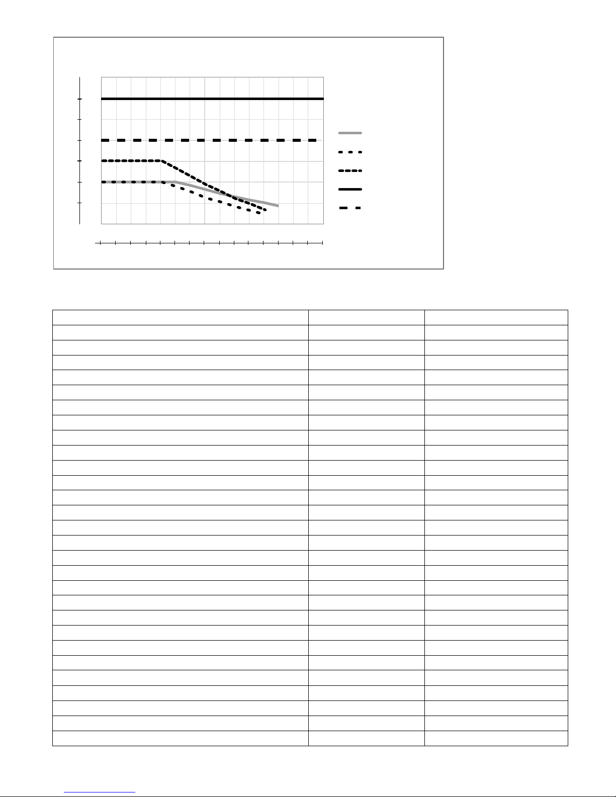
Note: Conductivity ranges on page 2 apply at 25°C. At higher temperatures, the range is reduced per the range multiplier
chart.
2.2 Electrical: Input/Output
Input Power 100 to 240 VAC, 50 or 60 Hz, 7 A maximum
Fuse: 6.3 A
Inputs
Copper/Nickel Sensor Signals (0, 1 or 2 depending on model code):
Copper Walchem 190787 immersible OR 190785, 190893, 191596 ow through
sensors
Nickel Walchem 190784 ow through sensor
Sensor Input Signals (0, 1 or 2 depending on model code):
Contacting Conductivity 0.01, 0.1, 1.0, or 10.0 cell constant OR
Electrodeless Conductivity (not available on the combination sensor/analog input card) OR
Disinfection OR
Amplied pH or ORP Requires a preamplied signal. Walchem WEL or WDS series recommended.
±5VDC power available for external preamps.
Each sensor input card contains a temperature input
3
Page 8

Temperature 100 or 1000 ohm RTD, 10K or 100K Thermistor (For Cu/Ni card, only
1000 ohm RTD)
Analog (4-20 mA) Sensor Input (0, 1,
2 or 4 depending on model code):
2-wire loop powered or self-powered transmitters supported
3 or 4 –wire transmitters supported
Each dual sensor input board has two channels
Channel 1, 130 ohm input resistance
Channel 2, 280 ohm input resistance
The combination input board has one channel, 280 ohm input resistance
Available Power:
One independent isolated 24 VDC ± 15% supply per channel
1.5 W maximum for each channel
2W (83 mA at 24 VDC) total power consumption for all channels (four
total channels possible if two dual boards are installed; 2W is equivalent to
2 Little Dipper sensors)
Digital Input Signals (6):
State-Type Digital Inputs
Electrical: Optically isolated and providing an electrically isolated 9V
power with a nominal 2.3mA current when the digital input switch is
closed
Typical response time: < 2 seconds
Devices supported: Any isolated dry contact (i.e. relay, reed switch)
Types: Interlock
Low Speed Counter-Type Digital
Inputs
Electrical: Optically isolated and providing an electrically isolated 9V
power with a nominal 2.3mA current when the digital input switch is
closed 0-10 Hz, 50 msec minimum width
Devices supported: Any device with isolated open drain, open collector,
transistor or reed switch
Types: Contacting Flowmeter
High Speed Counter-Type Digital
Inputs
Electrical: Optically isolated and providing an electrically isolated 9V
power with a nominal 2.3mA current when the digital input switch is
closed, 0-500 Hz, 1.00 msec minimum width
Devices supported: Any device with isolated open drain, open collector,
transistor or reed switch
Types: Paddlewheel Flowmeter
Outputs
Powered mechanical relays (0 or 6
depending on model code):
Dry contact mechanical relays (0, 2
or4 depending on model code):
Pulse Outputs (0, 2 or4 depending on
model code):
4 - 20 mA (0 or 2)
Ethernet
Pre-powered on circuit board switching line voltage
6 A (resistive), 1/8 HP (93 W)
All six relays are fused together as one group, total current for this group
must not exceed 6A
6 A (resistive), 1/8 HP (93 W)
Dry contact relays are not fuse protected
Opto-isolated, Solid State Relay
200mA, 40 VDC Max.
VLOWMAX = 0.05V @ 18 mA
Internally powered
Fully isolated
600 Ohm max resistive load
Resolution 0.0015% of span
Accuracy ± 0.5% of reading
10/100 802.3-2005
Auto MDIX support
Auto Negotiation
4
Page 9
Agency Approvals:
Safety UL 61010-1:2012 3rd Ed.
CSA C22.2 No. 61010-1:2012 3rd Ed.
IEC 61010-1:2010 3rd Ed.
EN 61010-1:2010 3rd Ed.
EMC IEC 61326-1:2012
EN 61326-1:2013
Note: For EN61000-4-6, EN61000-4-3 the controller met performance criteria B.
*Class A equipment: Equipment suitable for use in establishments other than domestic, and those directly connected
to a low voltage (100-240 VAC) power supply network which supplies buildings used for domestic purposes.
2.3 Mechanical
Enclosure Material Polycarbonate
Enclosure Rating NEMA 4X (IP65)
Dimensions 9.5” x 8” x 4” (241 mm x 203 mm x 102 mm)
Display 320 x 240 pixel monochrome backlit display with touchscreen
Operating Ambient Temp -4 to 131 °F (-20 to 55 °C)
Storage Temperature -4 – 176°F (-20 – 80°C)
Mechanical (Sensors) (*see graph)
Sensor Pressure Temperature Materials Process Connections
Immersible Copper Not applicable 32-200 F (0-93 C) Polypropylene, glass Not Applicable
Flow through Copper or
Nickel
Electrodeless conductivity 0-150 psi (0-10 bar)*
pH 0-100 psi (0-7 bar)* 50-158°F (10-70°C)* CPVC, Glass, FKM
ORP 0-100 psi (0-7bar)* 32-158°F (0-70°C)*
Contacting conductivity
(Condensate)
pH (High Pressure) 0-300 psi (0-21 bar)* 32-275°F (0-135°C)*
ORP (High Pressure) 0-300 psi (0-21 bar)* 32-275°F (0-135°C)*
Free Chlorine/Bromine 0-14.7 psi (0-1 bar) 32-113°F (0-45°C)
Extended pH Range Free
Chlorine/Bromine
Total Chlorine 0-14.7 psi (0-1 bar) 32-113°F (0-45°C)
Chlorine Dioxide 0-14.7 psi (0-1 bar) 32-131°F (0-55°C)
Ozone 0-14.7 psi (0-1 bar) 32-131°F (0-55°C)
Peracetic Acid 0-14.7 psi (0-1 bar) 32-131°F (0-55°C)
Hydrogen Peroxide 0-14.7 psi (0-1 bar) 32-113°F (0-45°C)
Flow switch manifold 0-150 psi (0-10 bar) up to 100°F (38°C)*
Flow switch manifold
(High Pressure)
0-14.7 psi (0-1 bar) 32-200 F (0-93 C) Polyethylene, glass, FKM
CPVC: 32-158°F (0 to 70°C)*
PEEK: 32-190°F (0 to 88°C)
0-200 psi (0-14 bar) 32-248°F (0-120°C) 316SS, PEEK 3/4” NPTM
0-14.7 psi (0-1 bar) 32-113°F (0-45°C)
32-140°F (0-60°C) GFRPP, PVC, FKM,
0-50 psi (0-3 bar) at 140°F (60°C)
0-300 psi (0-21 bar)* 32-158°F (0-70°C)*
CPVC, FKM in-line o-ring
PEEK, 316 SS in-line
adapter
o-rings, HDPE, Titanium
rod, glass-lled PP tee
Glass, Polymer, PTFE,
316SS, FKM
Platinum, Polymer, PTFE,
316SS, FKM
PVC, Polycarbonate,
silicone rubber, SS, PEEK,
FKM, Isoplast
Isoplast
Carbon steel, Brass,
316SS, FKM
3/8” OD tubing
compression ttings
1” NPTM submersion
2” NPTM in-line adapter
1” NPTM submersion
3/4” NPTF in-line tee
1/2” NPTM gland
1/2” NPTM gland
1/4” NPTF Inlet
3/4” NPTF Outlet
3/4” NPTF
3/4” NPTF
5
Page 10
Bar
24.1
20.7
17.2
13.8
10.3
6.9
3.4
PSI
350
300
250
200
150
100
50
Pressure vs. Temperature
pH/ORP
LD2
Cond
HP Cond/Steel
HP pH/ORP/Steel
0
30
40
50
60
70
80
90
100
110
120
130
140
150
160
°F
170
180
-1.1
4.4
10.0
15.5
21.1
26.6
32.2
37.7
43.3
48.8
54.4
60.0
65.5
71.1
76.6
82.2
°C
2.4 Variables and their Limits
Sensor Input Settings Low Limit High Limit
Calibration Offset (Copper or Nickel only) -10 g/l or oz/gal 10 g/l or oz/gal
Stabilization Time (Copper or Nickel only) 0:00 minutes 59:59 minutes
Alarm limits Low end of sensor range High end of sensor range
Input alarm dead band Low end of sensor range High end of sensor range
Cell constant (conductivity only) 0.01 10
Smoothing Factor 0% 90%
Temp Comp Factor (conductivity linear ATC only) 0% 20.000%
Installation Factor (Electrodeless conductivity only) 0.5 1.5
Cable length 0.1 3,000
PPM conversion factor (only if units = PPM) 0.001 10.000
Default temperature -5 500
Deadband Low end of sensor range High end of sensor range
Calibration Required Alarm 0 days 365 days
Sensor Slope (Generic sensor only) -1,000,000 1,000,000
Sensor Offset (Generic sensor only) -1,000,000 1,000,000
Low Range (Generic sensor only) -1,000,000 1,000,000
High Range (Generic sensor only) -1,000,000 1,000,000
4 mA value (Transmitter, AI Monitor analog input only) 0 100
20 mA value (Transmitter, AI Monitor analog input only) 0 100
Flow meter input settings Low Limit High Limit
Totalizer alarm 0 100,000,000
Volume/contact for units of Gallons or Liters 1 100,000
Volume/contact for units of m
K Factor for units of Gallons or Liters 0.01 100,000
K Factor for units of m
Smoothing Factor 0% 90%
Set Flow Total 0 1,000,000,000
Feed Monitor Input Settings Low Limit High Limit
3
3
0.001 1,000
1 1,000,000
6
Page 11

Totalizer Alarm 0 vol. units 1,000,000 vol. units
Set Flow Total 0 vol. units 1,000,000,000 vol. units
Flow Alarm Delay 00:10 Minutes 59:59 Minutes
Flow Alarm Clear 1 Contact 100,000 Contacts
Dead Band 0% 90%
Reprime Time 00:00 Minutes 59:59 Minutes
Volume/Contact 0.001 ml 1,000.000 ml
Smoothing Factor 0% 90%
Relay output settings Low Limit High Limit
Output Limit Time 1 second 86,400 seconds (0 = unlimited)
Hand Time Limit 1 second 86,400 seconds (0 = unlimited)
Min Relay Cycle 0 seconds 300 seconds
Set Point Low end of sensor range High end of sensor range
Spike Set Point (Spike mode) Low end of sensor range High end of sensor range
Onset Time (Spike Mode) 0 seconds 23:59:59 HH:MM:SS
Duty Cycle Period (On/Off, Spike, Dual Setpoint modes) 0:00 minutes 59:59 minutes
Duty Cycle (On/Off, Spike, Dual Setpoint modes) 0% 100%
On Delay Time (Manual, On/Off, Dual Setpoint modes) 0 seconds 23:59:59 HH:MM:SS
Off Delay Time (Manual, On/Off, Dual Setpoint modes) 0 seconds 23:59:59 HH:MM:SS
Dead Band Low end of sensor range High end of sensor range
Turnover Volume (Plating Control, Plating Follow modes) 0 10,000
Turnover Limit (Plating Control, Plating Follow modes) 0 100
Pump Capacity (Plating Control, Plating Follow modes) 0 1,000
Pump Setting (Plating Control, Plating Follow modes) 0% 100%
Feed duration (Flow Timer mode) 0 seconds 86,400 seconds
Accumulator volume (Flow Timer mode) 0 1,000,000
Event duration (Timer modes) 0 30,000
Proportional band (Time/Pulse Proportional mode) Low end of sensor range High end of sensor range
Sample period (Time Proportional mode) 0 seconds 3600 seconds
Hold Time (Probe Wash modes) 0 seconds 3600 seconds
Max Rate (Pulse Proportional, Pulse PID modes) 0% 100%
Minimum Output (Pulse Proportional, Pulse PID modes) 0% 100%
Maximum Output (Pulse Proportional, Pulse PID modes) 0% 100%
Gain (Pulse PID Standard mode) 0.001 1000.000
Integral Time (Pulse PID Standard mode) 0.001 seconds 1000.000 seconds
Derivative Time (Pulse PID Standard mode)us 0 seconds 1000.000 seconds
Proportional Gain (Pulse PID Parallel mode) 0.001 1000.000
Integral Gain (Pulse PID Parallel mode) 0.001 /second 1000.000 /second
Derivative Gain (Pulse PID Parallel mode) 0 seconds 1000.000 seconds
Input Minimum (Pulse PID modes) Low end of sensor range High end of sensor range
Input Maximum (Pulse PID modes) Low end of sensor range High end of sensor range
Wear Cycle Time (Lag mode) 10 seconds 23:59:59 HH:MM:SS
Delay Time (Lag mode) 0 seconds 23:59:59 HH:MM:SS
Analog (4-20 mA) Output Settings Low Limit High Limit
4 mA Value (Retransmit mode) Low end of sensor range High end of sensor range
20 mA Value (Retransmit mode) Low end of sensor range High end of sensor range
Hand Output 0% 100%
Set Point (Proportional, PID modes) Low end of sensor range High end of sensor range
7
Page 12

Proportional Band (Proportional mode) Low end of sensor range High end of sensor range
Minimum Output (Proportional, PID modes) 0% 100%
Maximum Output (Proportional, PID modes) 0% 100%
Off Mode Output (Proportional, PID modes, Flow Prop
modes)
Error Output (not in Manual mode) 0 mA 21 mA
Hand Time Limit (not in Retransmit mode) 1 second 86,400 seconds (0 = unlimited)
Output Time Limit (Proportional, PID modes) 1 second 86,400 seconds (0 = unlimited)
Gain (PID, Standard mode) 0.001 1000.000
Integral Time (PID Standard mode) 0.001 seconds 1000.000 seconds
Derivative Time (PID Standard mode) 0 seconds 1000.000 seconds
Proportional Gain (PID Parallel mode) 0.001 1000.000
Integral Gain (PID Parallel mode) 0.001 /second 1000.000 /second
Derivative Gain (PID Parallel mode) 0 seconds 1000.000 seconds
Input Minimum (PID modes) Low end of sensor range High end of sensor range
Input Maximum (PID modes) Low end of sensor range High end of sensor range
Target (Flow Prop mode) 0 ppm 1,000,000 ppm
Pump Capacity (Flow Prop mode) 0 gal/hour or l/hour 10,000 gal/hour or l/hour
Pump Setting (Flow Prop mode) 0% 100%
Specic Gravity (Flow Prop mode) 0 g/ml 9.999 g/ml
Conguration settings Low Limit High Limit
Local Password 0000 9999
VTouch update period 1 minute 1440 minutes
VTouch reply timeout 10 seconds 60 seconds
Alarm Delay 0:00 minutes 59:59 minutes
SMTP Port 0 65535
TCP Timeout 1 second 240 seconds
Auto Dim Time 0 seconds 23:59:59 HH:MM:SS
Graph settings Low Limit High Limit
Low axis limit Low end of sensor range High end of sensor range
High axis limit Low end of sensor range High end of sensor range
0 mA 21 mA
3.0 UNPACKING & INSTALLATION
3.1 Unpacking the unit
Inspect the contents of the carton. Please notify the carrier immediately if there are any signs of damage to the controller or
its parts. Contact your distributor if any of the parts are missing. The carton should contain a W600 series controller and an
instruction manual. Any options or accessories will be incorporated as ordered.
3.2 Mounting the electronic enclosure
The controller is supplied with mounting holes on the enclosure. It should be wall mounted with the display at eye
level, on a vibration-free surface, utilizing all four mounting holes for maximum stability. Use M6 (1/4” diameter)
fasteners that are appropriate for the substrate material of the wall. The enclosure is NEMA 4X (IP65) rated. The
maximum operating ambient temperature is 131°F (55°C); this should be considered if installation is in a high temperature location. The enclosure requires the following clearances:
Top: 2” (50 mm)
Left: 8” (203 mm) (not applicable for prewired models)
Right: 4” (102 mm)
Bottom: 7” (178 mm)
8
Page 13

3.3 Immersible Copper Sensor Installation
The immersible copper sensor is designed for direct in-tank monitoring of electroless copper and microetch solutions.
By monitoring the copper content directly in the solution, control lag and hydraulic problems are eliminated.
The sensor is constructed such that a constant path length exists between the ber optic light guides. The solution
between the light guides absorbs light at specic wavelengths in proportion to the copper concentration. The lamp and
electronics are located under the cover of the sensor. In order to avoid a shift in calibration due to condensation, the
sensor’s cover should NEVER be opened.
The immersible sensor is provided with a mounting plate and 20 feet of cable. Extension cable is available if the sensor cannot be mounted within 20 feet of the controller. The maximum cable length is 80 feet.
While the positioning of the sensor is not particularly sensitive to the tank layout, the following suggestions are given
to aid installation:
• Do not place the sensor beside heaters; if solution ow stops, the polypropylene guard may melt.
• Do not immerse the entire sensor, or the cable.
• Place the sensor where the loads of parts will not strike it.
• Place the sensor in an area of good solution movement, but not directly in the path of any air agitation.
• Mount the sensor securely to the rim of the tank using the holes provided. If the tank is rimless, use a block to
provide the support for the mounting plate.
• Attach the cable’s connector to the WCU controller. The connector is keyed, do not force! The sensor you
receive with the controller has already been calibrated.
3.4 Flow Through Copper Sensor/Sample Loop Installation
The copper ow through sensor is designed for out-of-tank monitoring of electroless copper and microetch solutions.
The sensor is designed with a glass tube that contains the copper solution that forms a xed path length between the
lamp and receptor module. The solution absorbs light at specic wavelengths in proportion to the copper concentra-
tion. In order to avoid a shift in calibration caused by condensation, the sensor cover should NEVER be removed!
The ow through sensor is provided with a mounting plate and 20 feet of cable. Extension cable is available if the
sensor cannot be placed within 20 feet of the controller. The maximum cable length is 80 feet.
The sample loop consists of a shut off valve, a cooling coil or plate, a sensor and a pump or any combination thereof.
The shut off valve is to quickly isolate the system if necessary. A cooling coil or plate is necessary to cool the copper solution down to a temperature acceptable to a sample pump. Cooling the solution is also recommended to help
reduce the amount of plate out which may form in the sample loop. The pump may be either a stand alone sample
pump (which typically have temperature restriction) or a high temperature pump (which is usually just a branch off
the recirculation pump).
3.5 Flow Through Nickel Sensor/Sample Loop Installation
The nickel ow through sensor is designed for out-of-tank monitoring of electroless nickel solutions.
The sensor is designed with a glass tube that contains the nickel solution that forms a xed path length between the
lamp and receptor module. The solution absorbs light at specic wavelengths in proportion to the nickel concentra-
tion. In order to avoid a shift in calibration caused by condensation, the sensor cover should NEVER be removed!
The ow through sensor is provided with a mounting plate and 20 feet of cable. Extension cable is available if the
sensor cannot be placed within 20 feet of the controller. The maximum cable length is 80 feet. Always route AC
9
Page 14

voltage wiring in conduit that is separated a minimum of 6 inches from low voltage DC signal lines (such as the sensor
signal).
The sample loop consists of a shut off valve, a cooling coil or plate, a sensor, an optional pH adapter assembly, a pump,
or any combination thereof. The shut off valve is to quickly isolate the system if necessary. A cooling coil or plate is
necessary to cool the nickel solution down to a temperature acceptable to a sample pump and/or pH electrode (if applicable). Cooling the solution is also recommended to help reduce the amount of plate-out that may form in the sample
loop. The pH adapter assembly is used to mount an in-line pH electrode. It should be mounted such that the electrode is
always immersed in the ‘U’ trap. The pump may be either a stand-alone sample pump (which will typically have high
temperature restrictions), or a high temperature pump (which is usually a branch off of the recirculation pump).
The ow through sensor/sample loop must be installed according to the following guidelines:
• Mount the sensor on a vibration-free, vertical surface so that the sensor tubing inlet connection is at the bottom and the
outlet is at the top. The vertical orientation will prevent air bubbles from being trapped in the sensor.
• Install a shut-off valve at the beginning of the sample loop so that the system may be shut off quickly if necessary.
• If a sample pump is to be used, it must be installed last, after the cooling coil or cooling plate, the ow through sensor,
and the pH adapter assembly, if applicable.
• If a high temperature recirculation pump is to supply ow, adjust ow rate through the sample loop between 400 - 500
mL/min (approx. 0.11 - 0.13 gal/min). This ow rate will help ensure adequate cooling of the solution while maintain
ing a reasonable lagtime in longer runs of tubing. If this is not possible or is undesirable, see Application Notes below.
Other installation guidelines that may be helpful in the overall system:
• Mount the sensor as close to solution as possible. Keep tubing distances to the sensor inlet as short as possible to avoid
hydraulic lag time. Maximum recommended length of tubing from solution to sensor is 25 feet. If this is not possible,
see Application Notes below.
• The solution inlet should draw sample from an area of good solution movement in order to respond quickly to
chemical additions. However, the solution inlet should not draw too near to where the chemistry is added to avoid
articial ‘spikes’ in concentration.
• The solution discharge should be open to atmospheric pressure in order to ensure proper ow.
• The cable connector to the controller is keyed, do not force!
Application Notes
If the distance from the solution to the sensor is further than the recommended length of 25 feet, the maximum lagtime
must be calculated from the desired control band to determine a pump ow rate based on a given distance of standard,
uniform tubing. The maximum lagtime is the maximum allowable time for the solution to continuously get to the sensor
in order to achieve the desired control band.
To calculate maximum lagtime:
Max. Lagtime = Desired Control Band*
4 x Depletion Rate
where Control band = Maximum deviation of concentration
Depletion rate = Rate at which the bath will deplete per unit of time
The deadband should be adjusted so that it is 1/4 the desired control band.
For Example: The set point is 4.00 g/L.
10
Page 15

If the desired control band is 0.20 g/L (± 0.10 g/L or 2.5%) and the bath is depleting at a rate of 1.25 g/L every
15 minutes (0.08333 g/L every minute),
then Max. Lagtime = 0.20 g/L = 0.60 minutes
4 x (0.08333 g/L /min)
So, 0.60 minutes is the maximum time it should take for the solution to reach the sensor.
To calculate pump ow rate:
Minimum Pump Flow Rate = Volume of System*
Maximum Lagtime
where Volume of system = π ( Tubing I.D.) 2 x Length of tubing
2
Maximum lagtime = Previously calculated time to get solution to sensor.
* Volume is based on length from solution to sensor, not the return.
For Example: If the system parameters are: Tubing is 3/8” O.D. ‘ 1/4” I.D.
Length is 30 feet (360 inches)
then the volume of the system = π ( 0.25 in )2 x (360 in)
2
= 17.7 in3
Note: 1 U.S. Gallon = 231 U.S cubic inches 1 Liter = 61.03 U.S. cubic inches
Note: Volume of Cooling Coil: 0.018 Gallons
0.068 Liters
Volume of 3/8” O.D. x 1/4” I.D. (0.59 in3/ft): 0.00255 Gallons/linear ft
0.00965 Liters/linear ft
Volume of Cooling Plate: 0.023 Gallons
0.088 Liters
Volume of the system = 17.7 in3 = 0.0765 gallons
231 in3 / gallon
Maximum lagtime = 0.60 minutes (previously calculated)
So, the minimum pump ow rate = 0.0765 gallons = 0.127gal/min (483 mL/min)
0.60 minutes
Caution: The calculated pump ow rate is the minimum required to obtain the desired control band, however, if the
ow rate increases over the recommended rate of 500 mL/min (approx. 0.13 gal/min) the rate of cooling will decrease.
This may be compensated for by re-evaluating the system criteria: length / desired control band or to double up on the
cooling plate/coil.
Consult factory with any further installation questions.
3.6 Other Sensor Installation
Refer to the specic instructions supplied with the sensor being used, for detailed installation instructions.
General Guidelines
11
Page 16

Locate the sensors where an active sample of water is available and where the sensors can easily be removed for
cleaning. Position the sensor such that air bubbles will not be trapped within the sensing area. Position the sensor
where sediment or oil will not accumulate within the sensing area.
In-Line Sensor Mounting
In-line mounted sensors must be situated so that the tee is always full and the sensors are never subjected to a
drop in water level resulting in dryness. Refer to Figure 3 for typical installation.
Tap off the discharge side of the recirculation pump to provide a minimum ow of 1 gallon per minute through
the ow switch manifold. The sample must ow into the bottom of the manifold in order to close the ow switch,
and return to a point of lower pressure in order to ensure ow. Install an isolation valve on both sides of the manifold to stop ow for sensor maintenance.
IMPORTANT: To avoid cracking the female pipe threads on the supplied plumbing parts, use no more than 3
wraps of Teon tape and thread in the pipe FINGER tight plus 1/2 turn! Do not use pipe dope to seal the threads
of the ow switch because the clear plastic will crack!
Submersion Sensor Mounting
If the sensors are to be submersed in the process, mount them rmly to the tank, and protect the cable with
plastic pipe, sealed at the top with a cable gland, to prevent premature failure. Place the sensors in an area of good
solution movement.
Sensors should be located such that they respond rapidly to a well-mixed sample of the process water and the
treatment chemicals. If they are too close to the chemical injection point, they will see spikes in concentration
and cycle on and off too frequently. If they are too far away from the chemical injection point, they will respond
too slowly to the concentration changes, and you will overshoot the set point.
The contacting conductivity sensor should be placed as close to the controller as possible, to a maximum
distance of 250 ft. (76 m). Less than 25 ft. (8 m) is recommended. The cable must be shielded from background
electrical noise. Always route low voltage (sensor) signals with at least a 6” (15 cm) separation from AC voltage wiring.
The electrodeless conductivity sensor should be placed as close to the controller as possible, to a maximum
distance of 120 ft. (37 m). Less than 20 ft. (6 m) is recommended. The cable must be shielded from background
electrical noise. Always route low voltage (sensor) signals with at least a 6” (15 cm) separation from AC voltage
wiring. These sensors are affected by the geometry and conductivity of their surroundings, so either maintain 6
inches (15 cm) of sample around the sensor or ensure that any nearby conductive or non-conductive items are
consistently positioned. Do not install the sensor in the path of any electrical current that may be owing in the
solution, as this will shift the conductivity reading.
The pH/ORP electrode should be placed as close to the controller as possible, to a maximum distance of 1000 feet
(305 m) from the controller. A junction box and shielded cable are available to extend the standard 20 foot (6 m)
length. pH and ORP electrodes must be installed such that the measuring surfaces will always remain wet. A U-trap
provided in the manifold design should achieve this, even if the sample ow stops. These electrodes also must be
installed with the measuring surfaces pointing down; that is 5 degrees above the horizontal, at a minimum.
The disinfection sensor should be placed as close to the controller as possible, to a maximum distance of 100
feet (30 m) from the controller. A junction box and shielded cable are available to extend the standard 20 foot (6
m) length. The sensor should be mounted such that the measuring surfaces will always stay wet. If the membrane
dries out, it will respond slowly to changing disinfectant values for 24 hours, and if dried out repeatedly, will fail
prematurely. The ow cell should be placed on the discharge side of a circulation pump or downhill from a gravity feed. Flow into the cell must come from the bottom side that has the ¾” x ¼” NPT reducing bushing installed.
The reducing bushing provides the ow velocity required for accurate readings and must not be removed! A “U”
trap should be installed so that if the ow stops, the sensor is still immersed in the water. The outlet of the ow
cell must be plumbed to open atmosphere unless the system pressure is at or below 1 atmosphere. If the ow
through the line cannot be stopped to allow for cleaning and calibration of the sensor, then it should be placed in
a by-pass line with isolation valves to allow for sensor removal. Install the sensor vertically, with the measuring
surface pointing down, at least 5 degrees above horizontal. Flow rate regulation must be done upstream from the
sensor, because any ow restriction downstream can increase the pressure above atmospheric and damage the
membrane cap!
12
Page 17
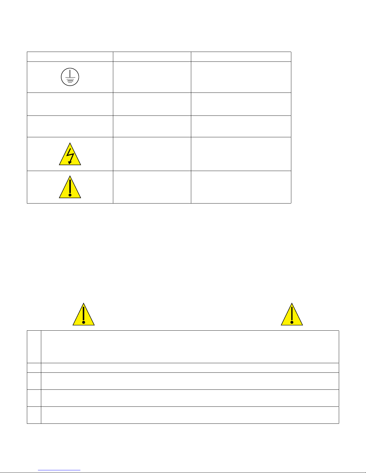
3.7 IconDenitions
Symbol Publication Description
IEC 417, No.5019 Protective Conductor Terminal
|
O
IEC 417, No. 5007 On (Supply)
IEC 417, No. 5008 Off (Supply)
ISO 3864, No. B.3.6 Caution, risk of electric shock
ISO 3864, No. B.3.1 Caution
3.8 Electrical installation
The various standard wiring options are shown in gure 1, below. Your controller will arrive from the factory prewired or ready for hardwiring. Depending on your conguration of controller options, you may be required to hardwire some or all of the input/output devices. Refer to gures 6 through 17 for circuit board layout and wiring.
Note: when wiring the optional ow meter contactor input, the 4-20 mA outputs or a remote ow switch, it is advis-
able to use stranded, twisted, shielded pair wire between 22-26 AWG. Shield should be terminated at the controller at
the most convenient shield terminal.
1. There are live circuits inside the controller even when the power switch on the front panel is in the OFF position! The front panel must never be opened before power to the controller is REMOVED!
If your controller is prewired, it is supplied with an 8 foot, 18 AWG power cord with USA style plug. A tool
(#1 Phillips driver) is required to open the front panel.
2. When mounting the controller, make sure there is clear access to the disconnecting device!
3. The electrical installation of the controller must be done by trained personnel only and conform to all applicable National, State and Local codes!
4. Proper grounding of this product is required. Any attempt to bypass the grounding will compromise the safety
of persons and property.
5. Operating this product in a manner not specied by Walchem may impair the protection provided by the equip-
ment.
CAUTION
13
Page 18
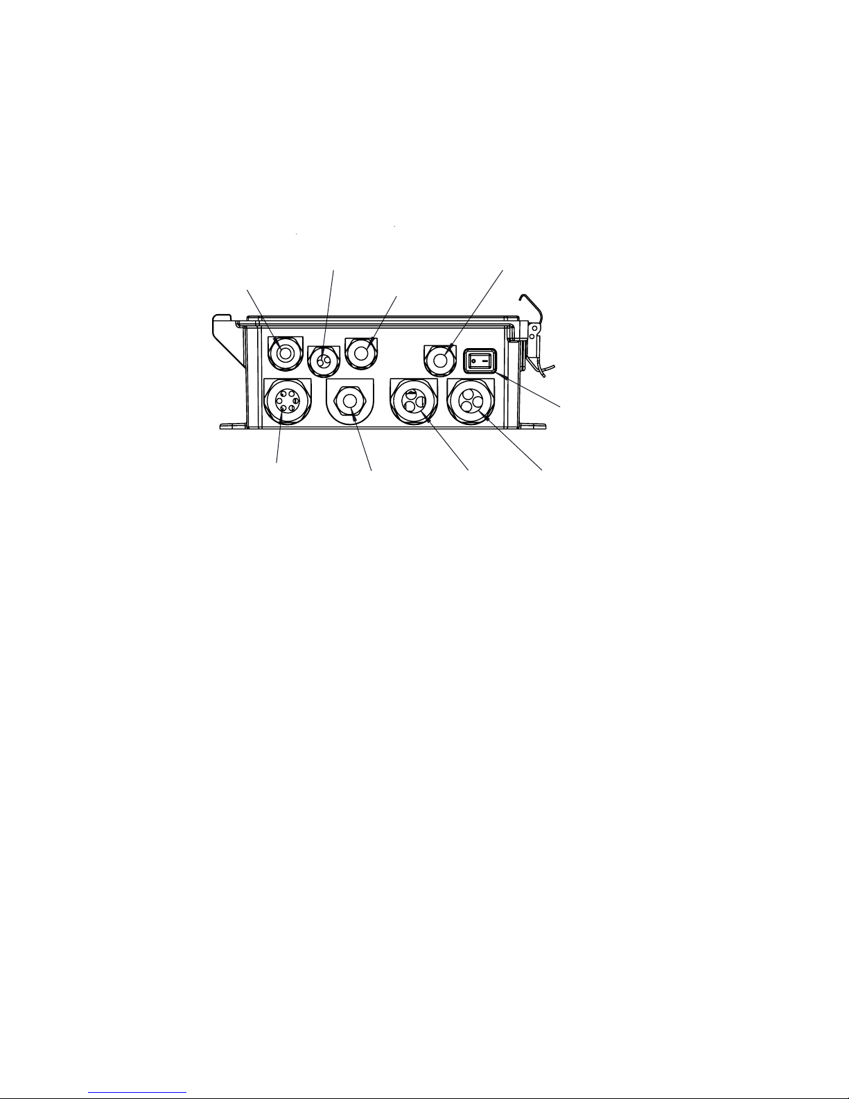
Ethernet
4-20 mA Outputs
Sensor 1
Power In
Power Switch
Digital Inputs
Sensor 2
Figure 1 Conduit Wiring
Relays Relays
14
Page 19
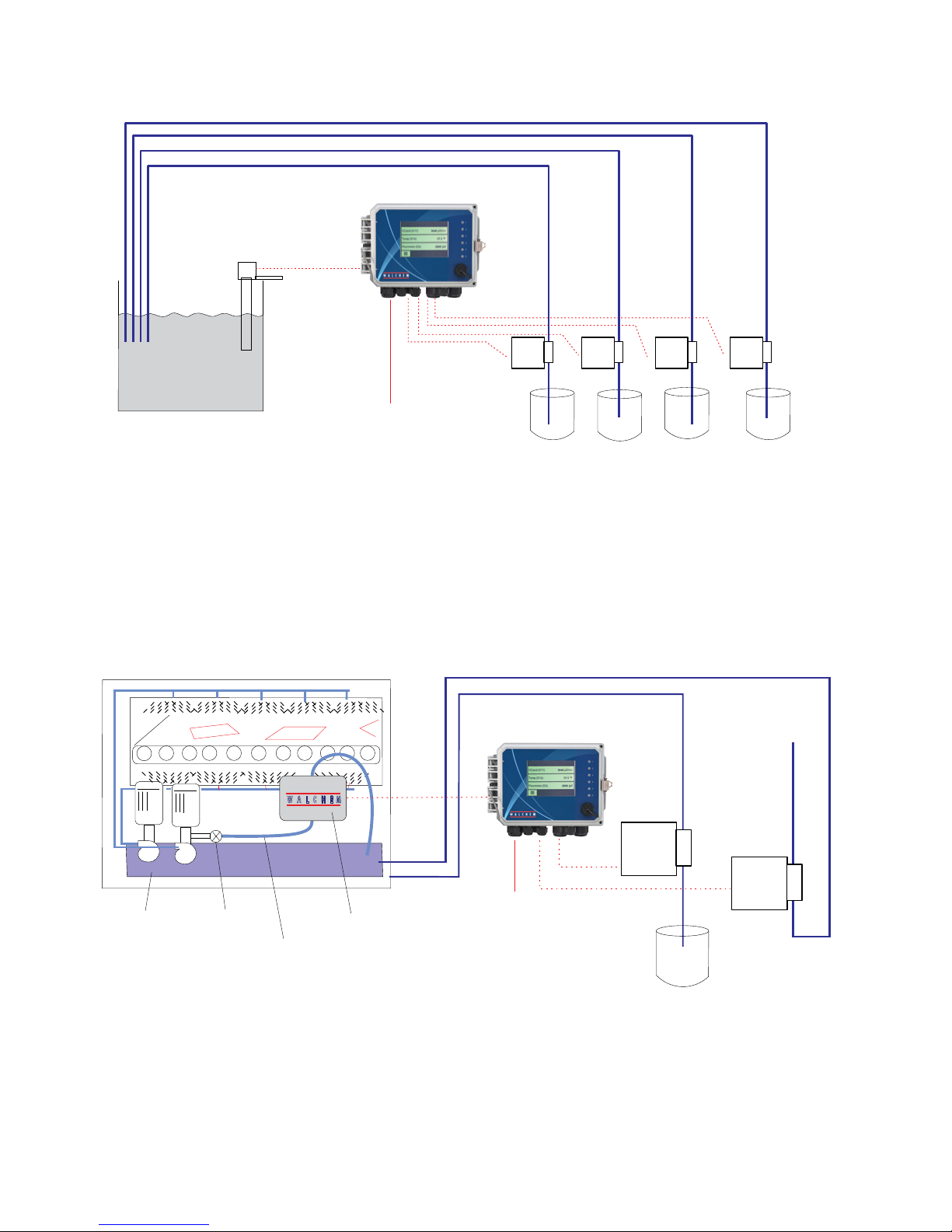
IMMERSIBLE
SENSOR
20 FT
(80 FT MAX.)
PLATING BATH
(TYPICAL ELECTROLESS COPPER APPLICATION)
CONVEYORIZED SPRAY EQUIPMENT
W A L C H E M
POWER
COPPER
WCU WITH IMMERSIBLE SENSOR
80 FT. MAX.
CAUSTIC
METERING PUMPS
FORMALDEHYDE
STABILIZER
TO
WASTE
TREATMENT
CIRCULATING
PUMPS
MANUAL
VALV E
3/8" TUBING
(< 20' PERFERRABLE)
WCU WITH FLOW-THROUGH SENSOR
(TYPICAL MICROETCH APPLICATION)
FLOW
THROUGH
SENSOR
POWER
Figure 2
15
SODIUM
PERSULFATE
"BLEED"
Page 20
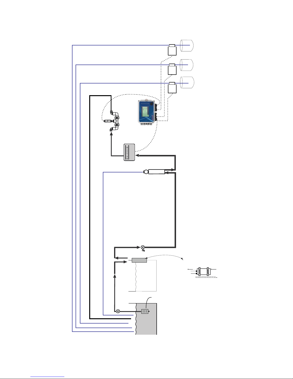
pH ELECTRODE
(recommended)
Copper/Nickel
Bath
pH ADAPTER
FLOW
THROUGH
SENSOR
MAX 80 FT
(24m)
OPTIONAL pH
REPLENISHER
REDUCER
NICKEL
Back to the bath
Shut-off valve
DEGASSER
FLOW ADJUSTMENT
VALV E
COIL
Filter
Pump
Rinse
COOLING
Warm
0
2
out
H
Sample
COOLING
COIL
Cool
0
2
in
H
WNI with Flow through Sensor and Degasser
(Typical Electroless Nickel Application)
Figure 3
16
Page 21
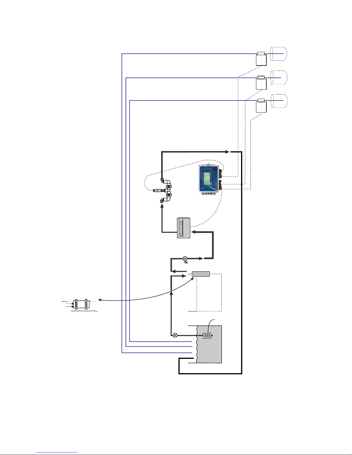
pH ELECTRODE
Copper/Nickel
pH ADAPTER
MAX 80 FT
(24 m)
OPTIONAL pH
REPLENISHER
REDUCER
NICKEL
Warm
0
2
out
H
Sample
COOLING
COIL)
FLOW
SENSOR
Cool
THROUGH
0
2
in
H
Shut-off valve
(recommended)
FLOW
ADJUSTMENT
VALV E
COOLING
COIL
Filter
Pump
Rinse
Bath
Figure 4
WNI with Flow Through Sensor, without Degasser
(Typical Electrodless Nickel Application)
17
Page 22
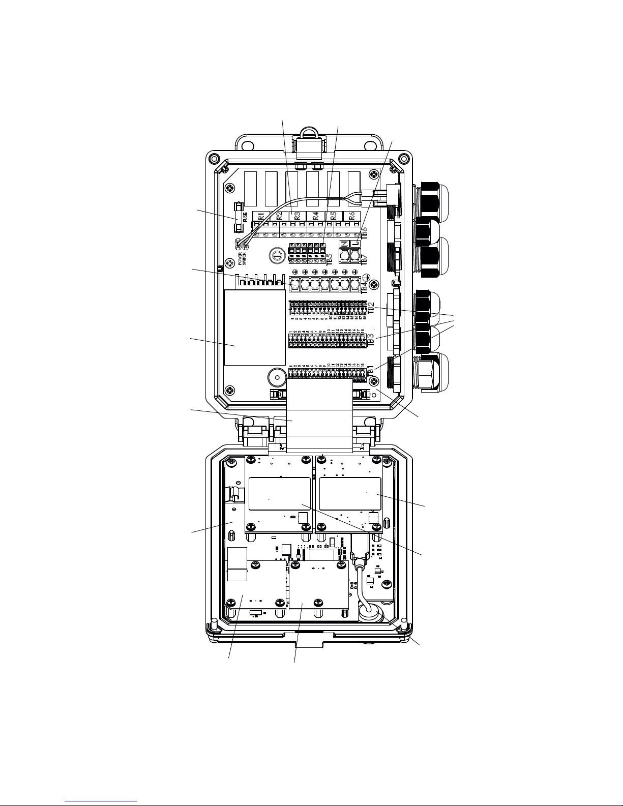
FUSE
ANALOG
OUTPUT
OPTION
ETHERNET
EARTH GROUND
TERMINAL BLOCK
RELAY OUTPUT
TERMINAL BLOCK
NEUTRAL
TERMINAL
BLOCK
AC POWER
TERMINAL
BLOCK
POWER SUPPLY
RIBBON CABLE
MAIN CONTROLLER BOARD
POWER
RELAY
BOARD
I/O SLOT 2
OPTION BOARD
I/O SLOT 1
BOARD
SENSOR, DIGITAL INPUT
AND ANALOG OUTPUT
TERMINAL BLOCKS
OPTION
DUAL
Figure5PartsIdentication
18
USB PORT
Page 23
Sensor 2
pH Cu/Ni
1
TEMP–
2
TEMP+
3
4
5
6
7
8
9
10
11
12
Cu/Ni SHIELD USE TB3 #12
IN–
IN+
–5V
+5V
COM
VM
VR
+5V
+2.5V
SHIELD
Sensor 1
1
2
3
4
5
6
7
8
9
10
11
12
18
1
1
2
2
3
3
4
4
5
5
6
6
7
7
8
8
9
9
10
10
11
11
12
12
13
13
14
14
15
15
16
16
17
17
18
18
TB1
TB3
TEMP– WHT/GRN
TEMP+ GRN/WHT
IN– WHT/ORN
IN+ ORN/WHT
–5V WHT/BLU
+5V BLU/WHT
COM WHT/BLU
VM ORN/WHT
VR GRN/WHT
+5V BLU/WHT
+2.5V WHT/GRN
SHIELD
1
2
3
4
5
6
7
8
9
10
11
12
13
14
15
16
17
18
TB4 TB6
TB2
POWER
SWITCH
FUSE
R1
R2
N
N
R3
N
N
N
N
N
N
R4
N
N
N
N
R5
TB5
R6
N
L
TB7
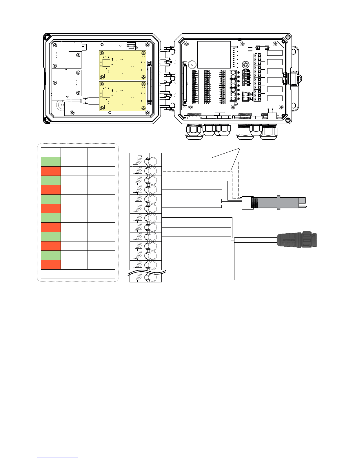
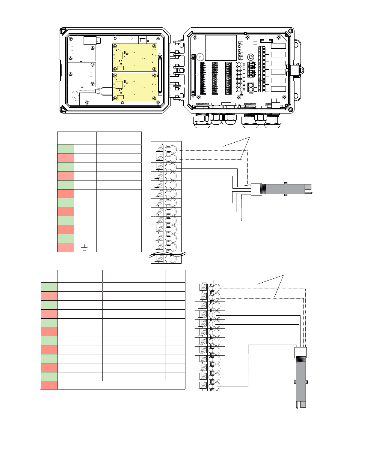
Optional Temperature
Compensation
pH electrode
Shield
to TB
3#12
Figure 6 - Copper/Nickel + pH Board Sensor Input Wiring
TB1 (for Sensor 1) or
TB2 (for optional Sensor 2)
19
Page 24
Sensor 1
Sensor 2
SENSOR INPUT CARD LABEL
ECOND CCOND
1
TEMP– TEMP– TEMP–
2
TEMP+ TEMP+ TEMP+
3
R-SHLD
4
RCV–
5
RCV+
6
7
X-SHLD SHIELD SHIELD
8
9
10
XMT+ XMT
XMT–
11
12
pH/ORP
DIS
IN–
RCV IN+
+5V
–5V
10
11
12
1
2
3
4
5
6
7
8
9
TB1 (for Sensor 1) or
TB2 (for optional Sensor 2)
18
CCOND
1
TEMP– TEMP–
2
TEMP+ TEMP+
3
SHIELD
4
RCV IN+
5
XMT
6
7
8
9
10
11
12
pH/ORP
DIS
IN–
–5V
+5V
SHIELD or use DI SHIELD (TB3 7-12)
2 Wire
Loop
+24V
XMTR–
2 Wire
Pwrd
3 Wire 4 Wire
COM(–)
+24V
24V(-)
+24V
XMTR– XMTR–
XMTR+ XMTR+ XMTR+
COMBINATION SENSOR/ANALOG CARD LABEL
1
1
2
2
3
3
4
4
5
5
6
6
7
7
8
8
9
9
10
10
11
11
12
12
13
13
14
14
15
15
16
16
17
17
18
18
TB1
TB3
TEMP– WHT
TEMP+ GRN
RCV BLACK
SHIELD
XMT RED
1
2
3
4
5
6
7
8
9
10
11
12
TB1 (for Sensor 1) or
TB2 (for optional Sensor 2)
1
2
3
4
5
6
7
8
9
10
11
12
13
14
15
16
17
18
TB4 TB6
TB2
POWER
SWITCH
N
N
N
N
N
N
N
N
N
N
N
N
TB5
N
L
TB7
General Purpose
(wiring is typical of all
three sensor options)
TEMP– WHT
TEMP+ GRN
SHIELD
RCV BLACK
XMT RED
FUSE
R1
R2
R3
R4
R5
R6
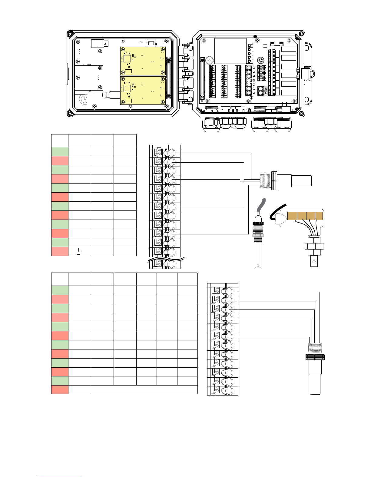
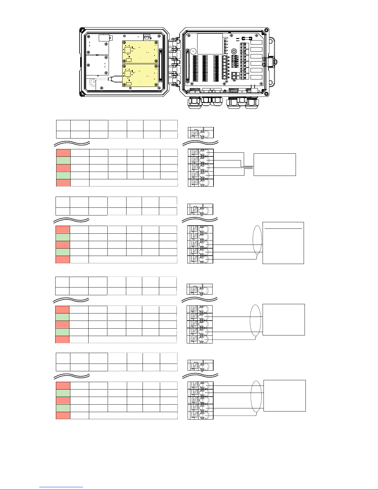
Conductivity
Electrode
GRN
WHT
High Pressure
RED
BLK
Conductivity
Electrode
Figure 7 Contacting Conductivity Sensor Input Wiring
20
Page 25
Sensor 1
Sensor 2
TB1
POWER
SWITCH
FUSE
R1
R2
1
1
2
3
4
5
6
7
8
9
10
11
12
13
14
15
16
17
18
TB3
1
2
2
3
3
4
4
5
5
6
6
7
7
8
8
9
9
10
10
11
11
12
12
13
13
14
14
15
15
16
16
17
17
18
18
TB2
N
N
N
N
N
N
N
N
N
N
N
N
TB5
N
L
TB7
TB4 TB6
R3
R4
R5
R6
ECOND CCOND
1
TEMP– TEMP– TEMP–
2
TEMP+ TEMP+ TEMP+
3
R-SHLD
4
RCV–
5
RCV+
6
7
X-SHLD SHIELD SHIELD
RCV IN+
8
9
10
XMT+ XMT
XMT–
11
12
SENSOR LABEL
pH/ORP
DIS
IN–
+5V
–5V
10
11
12
13
14
15
16
17
18
1
2
3
TEMP – BLK
TEMP + GRN
R-SHLD (SHIELD)
4
5
6
7
RCV – BLK
RCV + RED
X-SHLD (SHIELD)
8
9
XMT + WHT
XMT – BLK
Figure 8 Electrodeless Conductivity Sensor Input Wiring
TB1 (for Sensor 1) or
TB2 (for optional Sensor 2)
ELECTRODELESS
CONDUCTIVITY
SENSOR
21
Page 26
Sensor 1
Sensor 2
SENSOR INPUT CARD LABEL
ECOND CCOND
1
TEMP– TEMP– TEMP–
2
TEMP+ TEMP+ TEMP+
3
R-SHLD
4
RCV–
5
RCV+
6
7
X-SHLD
SHIELD SHIELD
8
9
10
XMT+ XMT
XMT–
11
12
pH/ORP
DIS
IN–
RCV IN+
+5V
–5V
10
11
12
18
POWER
SWITCH
1
1
2
3
4
5
6
7
8
9
10
11
12
13
14
15
16
17
18
TB1
1
2
3
4
TEMP– WHT/GRN
TEMP+ GRN/WHT
IN– WHT/ORN
IN+ ORN/WHT
1
2
2
3
3
4
4
5
5
6
6
7
7
8
8
9
9
10
10
11
11
12
12
13
13
14
14
15
15
16
16
17
17
18
18
TB4 TB6
TB2
TB3
FUSE
R1
R2
N
N
R3
N
N
N
N
N
N
R4
N
N
N
N
R5
TB5
R6
N
L
T
B7
Optional Temperature
Compensation
5
6
7
8
9
SHIELD
+5V BLU/WHT
-5V WHT/BLU
TB1 (for Sensor 1) or
TB2 (for optional Sensor 2)
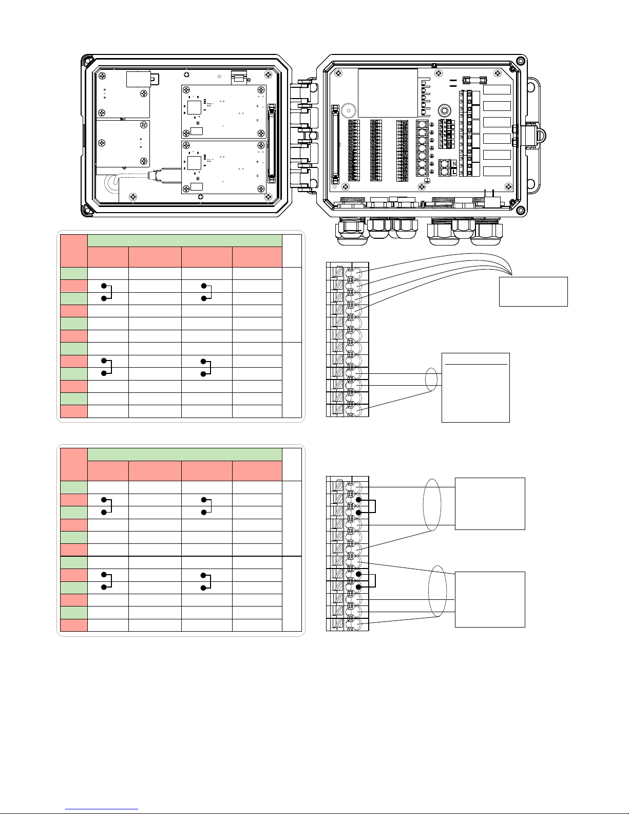
pH/ORP electrode
CCOND
1
TEMP– TEMP–
2
TEMP+ TEMP+
3
SHIELD
4
RCV IN+
5
XMT
6
7
8
9
10
11
12
pH/ORP
DIS
–5V
+5V
SHIELD or use DI SHIELD (TB3 7-12)
IN–
2 Wire
Loop
+24V
XMTR–
2 Wire
Pwrd
3 Wire 4 Wire
COM(–)
+24V
24V(-)
+24V
XMTR– XMTR–
XMTR+ XMTR+ XMTR+
COMBINATION SENSOR/ANALOG CARD LABEL
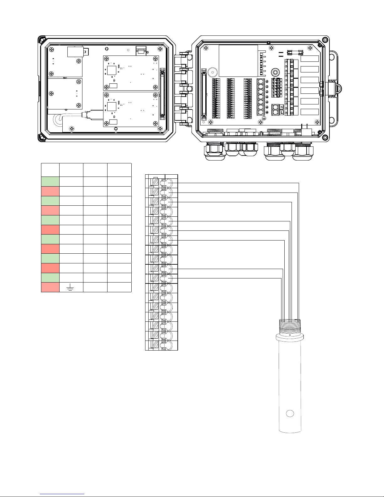
Figure 9 pH/ORP Sensor Input Wiring
1
2
3
4
5
6
7
8
9
10
11
12
TB1 (for Sensor 1) or
TB2 (for optional Sensor 2)
SHIELD
TEMP– WHT/GRN
TEMP+ GRN/WHT
IN– WHT/ORN
IN+ ORN/WHT
-5V WHT/BLU
+5V BLU/WHT
pH/ORP electrode
Optional Temperature
Compensation
22
Page 27
Sensor 1
Sensor 2
POWER
SWITCH
FUSE
R1
1
1
1
2
2
2
3
3
3
4
4
4
5
5
5
6
6
6
7
7
7
8
8
8
9
9
9
10
10
10
11
11
11
12
12
12
13
13
13
14
14
14
15
15
15
16
16
16
17
17
17
18
18
18
TB1
TB3
TB4 TB6
TB2
R2
N
N
R3
N
N
N
N
N
N
R4
N
N
N
N
R5
TB5
R6
N
L
B7
T
SENSOR LABEL
pH/ORP
CCOND
1
TEMP– TEMP–
8
9
10
11
12
CCOND
1
8
9
pH/ORP
TEMP– TEMP–
10
11
12
pH/ORP
CCOND
1
TEMP– TEMP–
8
9
10
11
12
2 Wire
2 Wire
DIS
Loop
Pwrd
3 Wire 4 Wire
COM(–)
+24V
+24V
XMTR– XMTR–
XMTR–
XMTR+ XMTR+ XMTR+
SHIELD or use DI SHIELD (TB3 7-12)
2 Wire
2 Wire
DIS
Loop
Pwrd
3 Wire 4 Wire
COM(–)
+24V
+24V
XMTR– XMTR–
XMTR–
XMTR+ XMTR+ XMTR+
SHIELD or use DI SHIELD (TB3 7-12)
2 Wire
2 Wire
DIS
Loop
Pwrd
3 Wire 4 Wire
COM(–)
+24V
+24V
XMTR– XMTR–
XMTR–
XMTR+ XMTR+ XMTR+
SHIELD or use DI SHIELD (TB3 7-12)
24V(-)
+24V
24V(-)
+24V
24V(-)
+24V
TB1 (for Sensor 1) or
TB2 (for optional Sensor 2)
1
8
9
10
11
12
1
8
9
10
11
12
1
8
9
10
11
12
GROUND
POWER
-
+
–
+
SHIELD
+
–
SHIELD
POWERED
4 WIRE
TRANSMITTER
POWERED 2 WIRE
4-20mA SOURCE
•SIMULATOR
•POWERED 4-20mA
OUTPUT
(e.g. W100)
UNPOWERED
2 WIRE
LOOP POWERED
TRANSMITTER
CCOND
1
TEMP– TEMP–
pH/ORP
DIS
2 Wire
Loop
8
9
+24V
10
11
12
XMTR–
SHIELD or use DI SHIELD (TB3 7-12)
NOTE: To program the combination card analog input, you must go to Inputs menu, then enter the analog input
(S13 or S23), scroll down to Transmitter, and select the type of transmitter from the list.
Figure 10 Combination Card 4-20mA Dual Sensor Input Wiring
2 Wire
3 Wire 4 Wire
Pwrd
COM(–)
24V(-)
+24V
+24V
XMTR– XMTR–
XMTR+ XMTR+ XMTR+
10
11
12
1
UNPOWERED
8
9
– GROUND
24V POWER
+ SIGNAL
SHIELD
3 WIRE
TRANSMITTER
23
Page 28
TB
Pin#
1
2
3
4
5
6
7
8
9
10
11
12
TB
Pin#
1
2
3
4
5
6
7
8
9
10
11
12
2 Wire
Loop
+24V
XMTR–
SHIELD
+24V
XMTR–
SHIELD
2 Wire
Loop
+24V
XMTR–
SHIELD
+24V
XMTR–
SHIELD
Type of Transmitter
2 Wire
Powered
XMTR–
XMTR+
SHIELD
XMTR–
XMTR+
SHIELD
3 Wire
+24V
XMTR+
COM(-)
SHIELD
+24V
XMTR+
COM(-)
SHIELD
Type of Transmitter
2 Wire
Powered
XMTR–
XMTR+
SHIELD
XMTR–
XMTR+
SHIELD
3 Wire
+24V
XMTR+
COM(-)
SHIELD
+24V
XMTR+
COM(-)
SHIELD
4 Wire
+24V
24V(–)
XMTR–
XMTR+
SHIELD
+24V
24V(–)
XMTR–
XMTR+
SHIELD
4 Wire
+24V
24V(–)
XMTR–
XMTR+
SHIELD
+24V
24V(–)
XMTR–
XMTR+
SHIELD
AI#
1
2
AI#
1
2
1
1
2
3
4
5
6
7
8
9
10
11
12
13
14
15
16
17
18
TB1
1
2
3
2
3
4
5
6
7
8
9
10
11
12
13
14
15
16
17
18
TB3
Power
Ground
–
1
2
3
4
5
6
7
8
9
10
11
12
13
14
15
16
17
18
TB2
+
4
5
6
7
8
9
10
11
–
+
Shield
12
TB1 (for Sensor 1) or
TB2 (for optional Sensor 2)
1
2
3
Jumper
wire
4
5
Shield
6
7
8
9
10
11
12
24V Power
Jumper
wire
+ Signal
– Ground
Shield
TB1 (for Sensor 1) or
TB2 (for optional Sensor 2)
POWER
SWITCH
N
N
N
N
N
N
N
N
N
N
N
N
TB5
N
L
TB7
TB4 TB6
POWERED
4-20mA SOURCE
•SIMULATOR
•POWERED 4-20mA
OUTPUT
(i.e. W100)
+
–
FUSE
R1
R2
R3
R4
R5
R6
UNPOWERED
2 WIRE
TRANSMITTER
UNPOWERED
3 WIRE
TRANSMITTER
POWERED
4 WIRE
TRANSMITTER
Figure 11 Dual 4-20mA Sensor Input Wiring
24
Page 29
TB1
POWER
SWITCH
FUSE
R1
R2
1
1
2
3
4
5
6
7
8
9
10
11
12
13
14
15
16
17
18
TB3
1
2
2
3
3
4
4
5
5
6
6
7
7
8
8
9
9
10
10
11
11
12
12
13
13
14
14
15
15
16
16
17
17
18
18
TB2
N
N
N
N
N
N
N
N
N
N
N
N
TB5
N
L
TB7
TB4 TB6
R3
R4
R5
R6
1
2
3 3 +9 VDC
4 4
5 5
SEE
6 6 +9 VDC
SENSOR 1
7 7
LABEL
8 8
9 9
1
2
DIG IN 3+
DIG IN 3–
DIG IN 4+
DIG IN 4–
DI
SHIELD
1
2
3
4
5
6
7
8
9
SEE
SENSOR 2
LABEL
10 10 10
11 11 11
12 12 12
13 DIG IN 1+ 13 DIG IN 5+ 13 DIG IN 2+
14 DIG IN 1– 14 DIG IN 5– 14 DIG IN 2–
15
+9 VDC
16
4-20 OUT1+
17
4-20 OUT1–
18
SHIELD
15
+9 VDC
15
16 DIG IN 6+ 16
17 DIG IN 6– 17
18
+9 VDC
18
+9 VDC
4-20 OUT2+
4-20 OUT2–
SHIELD
TB1 TB3 TB2
SAFETY COVER LABEL
1
2
3
4
5
6
7
8
9
10
11
12
13
14
15
16
17
18
TB1, 2 OR 3
(TB 3 SHOWN)
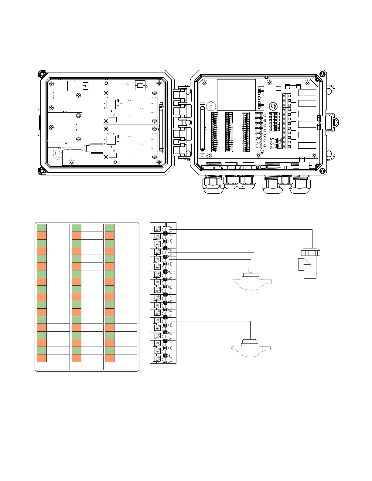
SIGNAL
IN –
POWER +9V
Hall Effect
FLOW METER
Reed Switch
FLOW METER
Polarity not Critical
FLOW SWITCH
Contact Closure:
Polarity not critical
Figure 12 Digital Inputs
25
Page 30
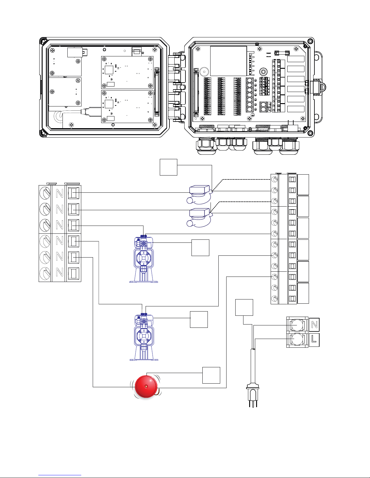
N
N
N
N
N
N
TB5
WHT 120V
BLU 240V
WHT 120V
BLU 240V
WHT 120V
BLU 240V
WHT 120V
BLU 240V
WHT 120V
BLU 240V
PUMP
GRN 120V
TO
TB4
SOLENOID/
MOTORIZED
BALL VALVE
GRN 120V
GRN/YEL 240V
GRN 120V
GRN/YEL 240V
GRN/YEL 240V
TO
TB4
TO
TB4
TB1
POWER
SWITCH
FUSE
R1
R2
1
1
2
3
4
5
6
7
8
9
10
11
12
13
14
15
16
17
18
2
3
4
5
6
7
8
9
10
10
11
11
12
12
13
13
14
14
15
15
16
16
17
17
18
18
TB3
IF MOTORIZED
BALL VALVE
1
2
3
4
5
6
7
8
9
TB2
BLK 120V
BRN 240V
N
N
N
N
N
N
N
N
N
N
N
N
TB5
N
L
TB7
TB4 TB6
R3
R4
R5
R6
NC
NO
R1
NC
BLK 120V
BRN 240V
NO
R2
NC
BLK 120V
BRN 240V
NO
R3
NC
BLK 120V
BRN 240V
NO
R4
NC
BLK 120V
BRN 240V
NO
R5
NC
R6
TO
TB4
TB6
WHT 120V
BLU 240V
BLK 120V
BRN 240V
NO
N
L
Figure 13 W600 AC Power + Relay Output Wiring
PUMP
ALARM
GRN 120V
GRN/YEL 240V
26
TO
TB4
GRN 120V
GRN/YEL 240V
Power Supply
(115 VAC or 230 VAC)
TB7
Page 31

GRN 120V
GRN/YEL 240V
N
N
N
GRN 120V
GRN/YEL 240V
TB5
Fused
External
Power
Source
WHT 120V
BLU 240V
WHT 120V
BLU 240V
GRN 120V
GRN/YEL 240V
WHT 120V
BLU 240V
BLK 120V
BRN 240V
1
2
3
4
5
6
7
8
9
10
11
12
13
14
15
16
17
18
TB1
PLC
1
2
3
4
5
6
7
8
9
10
11
12
13
14
15
16
17
18
TB3
BLK 120V
BRN 240V
BLK 120V
BRN 240V
1
2
3
4
5
6
7
8
9
10
11
12
13
14
15
16
17
18
TB4
TB2
If motorized
ball valve
BLK 120V
BRN 240V
POWER
SWITCH
TB5
FUSE
NC
R1
NO
NC
R2
NO
N
N
N
N
TB7
R3
N
N
N
R4
N
N
R5
N
R6
L
TB6
NC
R1
NO
NC
R2
NO
R3
R4
TB4
GRN 120V
GRN/YEL 240V
(115 VAC or 230 VAC)
WHT 120V
BLU 240V
BLK 120V
BRN 240V
Power Supply
Fused
External
Power
Source
TB7
GRN 120V
GRN/YEL 240V
WHT 120V
BLU 240V
BLK 120V
BRN 240V
ALARM
N
L
Figure 14 W610 AC Power and Relay Wiring
27
R5
R6
TB6
Page 32

TB7
GRN 120V
GRN/YEL 240V
External
AC
Power
TB1
POWER
SWITCH
1
1
2
3
4
5
6
7
8
9
10
11
12
13
14
15
16
17
18
TB3
1
2
2
3
3
4
4
5
5
6
6
7
7
8
8
9
9
10
10
11
11
12
12
13
13
14
14
15
15
16
16
17
17
18
18
TB2
TB4
TB5
TB7
FUSE
+
R1
–
+
R2
–
N
R3
N
N
N
R4
N
N
R5
N
R6
L
TB6
+
TB4
Fused
External
Power
Source
WHT 120V
BLU 240V
BLK 120V
BRN 240V
External
AC
Power
Fused
External
Power
Source
GRN 120V
GRN/YEL 240V
WHT 120V
BLU 240V
GRN 120V
GRN/YEL 240V
WHT 120V
BLU 240V
N
L
BLK 120V
BRN 240V
PLC
ALARM
BLK 120V
BRN 240V
BLK 120V
BRN 240V
–
+
–
R1
R2
R3
R4
R5
R6
TB6
Figure 15 W620 AC Power & Relay Output Wiring
28
Page 33

External
AC
Power
TB1
POWER
SWITCH
1
1
2
3
4
5
6
7
8
9
10
11
12
13
14
15
16
17
18
TB3
1
2
2
3
3
4
4
5
5
6
6
7
7
8
8
9
9
10
10
11
11
12
12
13
13
14
14
15
15
16
16
17
17
18
18
TB2
TB4
TB5
TB7
FUSE
+
R1
–
+
R2
–
+
N
R3
N
–
N
+
N
R4
N
–
N
R5
N
R6
L
TB6
+
TB4
GRN 120V
GRN/YEL 240V
WHT 120V
BLU 240V
BLK 120V
BRN 240V
External
AC
Power
External
AC
Power
External
AC
Power
TB7
N
L
Fused
External
Power
Source
GRN 120V
GRN/YEL 240V
WHT 120V
BLU 240V
BLK 120V
BRN 240V
PLC
ALARM
–
+
–
+
–
+
–
R1
R2
R3
R4
R5
R6
TB6
Power Supply
(115 VAC or 230 VAC)
Figure 16 W640 AC Power & Relay Output Wiring
29
Page 34

TB1
POWER
SWITCH
FUSE
R1
R2
1
1
2
3
4
5
6
7
8
9
10
11
12
13
14
15
16
17
18
TB3
1
2
2
3
3
4
4
5
5
6
6
7
7
8
8
9
9
10
10
11
11
12
12
13
13
14
14
15
15
16
16
17
17
18
18
TB2
N
N
N
N
N
N
N
N
N
N
N
N
TB5
N
L
TB7
TB4 TB6
R3
R4
R5
R6
Chart
Recorder
+
–
SHIELD
TB1
1
1
2
2
3 3
3
4 4
4
5 5
5
6
7
8
9
10
11
12
13
14
15
16
17
18
SEE
6 6
SENSOR 1
7 7
LABEL
8 8
9 9
10 10 10
11 11 11
12 12 12
13 DIG IN 1+ 13 DIG IN 5+ 13 DIG IN 2+
14 DIG IN 1– 14 DIG IN 5– 14 DIG IN 2–
15
+9 VDC
16
4-20 OUT1+
17
4-20 OUT1–
18
SHIELD
1
DIG IN 3+
DIG IN 3–
2
+9 VDC
DIG IN 4+
DIG IN 4–
+9 VDC
DI
SHIELD
15
+9 VDC
16 DIG IN 6+ 16
17 DIG IN 6– 17
18
+9 VDC
TB1 TB3 TB2
SAFETY LABEL
1
2
3
4
5
6
SENSOR 2
7
8
9
15
+9 VDC
4-20 OUT2+
4-20 OUT2–
18
SHIELD
SEE
LABEL
10
11
12
13
14
15
16
17
18
1
2
3
4
5
6
7
8
9
TB2
+
–
SHIELD
Chart
Recorder
Figure 17 Analog Output Wiring
30
Page 35

4.0 FUNCTION OVERVIEW
4.1 Front Panel
Figure 18 Front Panel
4.2 Touchscreen
A Home screen is displayed while the controller is on. This display shows a user-dened list of input readings or status
of outputs. Touching any of the items on the Home Screen will bring up the item’s Details Screen, where you can access
calibration and setting menus. If more than four items have been selected to be displayed on the Home screen, the display
will toggle between the rst group of up to four and the next group. A “pause button” icon, when touched, stops the
automatic toggling. Touching the down arrow icon allows for manual toggling. Touching the “play button” icon enables
automatic toggling again. Touching the Menu icon brings up the Main Menu screen.
4.3 Icons
The following icons appear on the Home screen.
The Main Menu icon brings you to the list of menu options listed below.
The following icons appear on the Main Menu screen. Touch the icon to get to the menu selections.
Alarm Menu
Inputs Menu
31
Page 36

Outputs Menu
X
X
Conguration Menu
HOA Menu
Graph Menu
Home Page
Other icons may appear in the menu screens.
Calibration icon appears in sensor input menus and brings up the calibration menu
Cancel icon aborts a calibration or setting change
The Page Down icon scrolls down to a new page in a list of options.
The Page Up icon scrolls up to a new page in a list of options.
The Back/Return icon returns the display to the previous screen
The Make Character Higher icon is used when making an alphanumeric entry
The Make Character Lower icon is used when making an alphanumeric entry
The Move Cursor icon is used to scroll left to right within an alphanumeric entry
The Conrm icon accepts a choice, nishes entering data, or advances to the next calibration step
Settings Menu
The Character Delete icon deletes part of an alphanumeric entry
The Shift icon switches between upper and lower case alpha entry screens
The Next Screen icon moves to the next step in a calibration sequence. In a Graph it shifts the
graph forward in time.
The Previous Screen icon moves back a step in a calibration sequence. In a Graph it shifts the
graph backwards in time.
32
Page 37

Overview of the use of icons
Changing Numeric Values
To change a number, use the Character Delete icon to the digit to be changed. If the new number will be negative, start with touching the minus sign, then use the numeric touchpad and decimal point to type the number
(some entries must be integers and the decimal will be ignored and the setting rounded to the nearest integer).
Once the value of the number is correct touch the Conrm icon to store the new value into memory, or touch the
Cancel icon to leave the number at its previous value and go back.
Changing Names
To change the name used to identify an input or output, use the Move Cursor icon to the character to be changed
and change it using either the Make Character Higher or Lower icons. Upper case and lower case letter, numbers,
a blank space, period, plus and minus symbols are available. Move the cursor to the right and modify each character. Once the word is correct, use the Enter icon to store the new value into memory, or use the Cancel icon to leave
the word at its previous value and go back.
Choosing from a List
Selecting the type of sensor, the units of measure of an input, or the control mode used for an output, the selec-
tion is picked from a list of available options. Touch the Page Up or Down icons if necessary to nd the desired
option, and then touch the option to highlight it. Touch the Conrm icon to store the new option into memory, or
touch the Cancel icon to leave the selection at its previous value and go back.
Hand-Off-Auto Relay Mode
Touch the desired relay mode. In Hand mode the relay is forced on for a specied amount of time and when that
time is up the relay returns to its previous mode, in Off mode the relay is always off until taken out of Off mode,
and in Auto mode the relay is responding to control set points. Touch the Return icon to go back to the relay
settings.
Interlock and Activate with Channels Menus
To select which digital inputs or relays will interlock this relay (Interlock Channels), or which digital inputs or
relays will force this relay on (Activate with Channels), touch the input or relay number(s). The background of
the selected item will turn dark. When nished selecting as many as needed, touch the Conrm icon to accept the
changes or the Cancel icon to leave the selections at the previous settings and go back.
4.4 Startup
Inputs (see section 5.2)
Program the settings for each input
The S11 sensor input will be displayed. Touch it to get to the Details screen. Touch the Settings icon. If the name of
the sensor does not describe the type of sensor connected, touch the Scroll Down icon until Type is displayed. This
should be the copper/nickel sensor input. Touch the Type eld. Touch the Scroll Down icon until the correct type of
sensor is displayed, then touch it to highlight it. Touch the Conrm icon to accept the change. This will bring you
back to the Settings screen. Finish the rest of the S11 settings. For copper/nickel sensors select the units of measure.
The S12 input is the optional pH input for electroless nickel, if a pH sensor will be used, change the Type from No
Sensor to pH. This will bring you back to the Settings screen. Finish the rest of the S12 settings.
The S13 temperature input Element should be set to RTD 1000Ω if the S12 pH sensor includes a temperature
element. If so, set the alarm set points and alarm deadband. To calibrate the temperature, return to the S13 Details
screen, touch the Calibrate icon, and touch the Enter icon to perform a calibration.
If the other input card is a Dual Analog Input card (4-20mA signal), then select the type of sensor that will be connected. Select AI Monitor if the device can be calibrated on its own and the W600 calibration will only be in units
of mA. Select Transmitter if the device connected cannot be calibrated on its own and the W600 will need to be
used to calibrate in engineering units of measure.
33
Page 38

If a ow switch or liquid level switch is connected, D1 through D6 (whichever one has the device connected to it)
should be set to DI State type (if no switch is connected, select No Sensor). Set the state that will possibly interlock
control outputs (refer to the Outputs settings to program which outputs, if any, will be interlocked by the switch).
Set the state, if any, that will result in an alarm.
If a contacting head or paddlewheel ow meter is connected, D1 through D6 (whichever one has the device connected to it) should be set to that type (if no ow meter is connected, select No Sensor). Set the units of measure,
volume/contact or K factor, etc.
Calibrate the copper/nickel and optional pH sensor
To calibrate the sensor, return to the list of inputs, touch the sensor to calibrate, touch the Calibrate icon, and select
one of the calibration routines. For copper/nickel sensors, start with a Water/Sample Calibration. After that, a calibration offset setting can be applied, to match the reading to a titration, from the Settings menu. Refer to section 5.2.
Touch the Main Menu icon. Touch the Outputs icon.
34
Page 39

Inputs
Nickel (S11) 7.00 g/l
pH (S12) 4.50
Temp (S13) 77.1 F
Generic AI (S21) 30.5%
>
List of possible Inputs:
Copper
Nickel
Contacting Conductivity
Electrodeless Conductivity
Temperature
pH
ORP
Disinfection
Generic
Transmitter/AI Monitor
DI State
Flow Meter, Contactor type
Flow Meter, Paddlewheel type
Feed Monitor
Virtual Input
Outputs
On/Off (R1) Off
Flow Timer (R2) Off
Flow Timer (R3) Off
Manual (R4) Off
>
MAIN MENU/HOME SCREEN OVERVIEW
HOME SCREEN (example)
Flowswitch (D1) No Flow
SENSOR (S1)
Nickel (S11) 7.00 g/l
pH 4.50.°F
Temp (S13) 77.0°F
MAIN MENU
Main Menu 09:19:01 14-Mar-2017
Inputs
Outputs
Alarm
Config
HOA
Graph
Config
Global Settings
Security Settings
Network Settings
Network Details
>
Additional Confg Settings:
Remote Communications (Modbus)
Email Report Settings
Display Settings
File Utilities
Controller Details
> HOA
R1 R2 R3
R4 R5 R6
List of possible Outputs:
Plating Control
Plating Follow
On/O control mode
Flow Timer control mode
Percent Timer control mode
Alarm Output mode
Time Proportional control mode
Manual control mode
Pulse Proportional control mode
PID control mode
Dual Setpoint mode
Timer control mode
Probe Wash control mode
Spike control mode
Lag Output control mode
Analog Ouput, Retransmit mode
Analog Output, Proportional control mode
Analog Output, PID control mode
Analog Output, Manual mode
Analog Output, Flow Proportional mode
Alarms
List of all Active Alarms
To HOME SCREEN
Graph Settings
SENSOR (S1)
Sensor
DI Relay
Low Axis Limit
High Axis Limit
>
Additional Graph Settings:
Time Range
Hand
CCond (S11) On/Off (R2)
µS/cm
3036
3035
3034
3033
3032
3031
Off Auto
10.35 10.40 10.4514-Nov
Minutes
Time Range
SENSOR (S1)
10 Minutes
30 Minutes
1 Hour
2½ Hours
X
More possible settings:
8 Hours 1 Week
12 Hours 2 Weeks
1 Day 4 Weeks
½ Week
>
10
35
Page 40

Inputs
Nickel (S11) 7.00 g/l
ph (S12) 4.50
Temp (S13) 77.1°F
Generic AI (S21) 30.5%
>
Main Menu 09:19:01 14-Mar-2017
Inputs
Outputs
Alarms
Config
HOA
Graph
Contacting Cond S11 (22)
Alarms
Deadband
Reset Calibration Values
Cal Required Alarm
Electrodeless Cond S11 (S21)
Alarms
Deadband
Reset Calibration Values
Cal Required Alarm
Temperature S12 (S22)
SENSOR (S1)
Alarms
Deadband
Reset Calibration Values
Cal Required Alarm
pH S11 (S21)
SENSOR (S1)
Alarms
Deadband
Reset Calibration Values
Cal Required Alarm
ORP S11 (S21)
SENSOR (S1)
Alarms
Deadband
Reset Calibration Values
Cal Required Alarm
Disinfection S11 (S21)
SENSOR (S1)
Alarms
Deadband
Reset Calibration Values
Cal Required Alarm
Generic S11 (S21)
SENSOR (S1)
Alarms
Deadband
Reset Calibration Values
Cal Required Alarm
>
>
>
>
>
>
>
>
>
>
>
>
>
>
> Calibration
SENSOR (S1)
Water/Sample Calibration
One Point Process Calibration
One Point Buffer Calibration
Two Point Buffer Calibration
Three Point Buffer Calibration
One Point Analog Calibration
Two Point Analog Calibration
Open Air Calibration (Cond)
Zero Calibration (Disinfection)
Additional Settings for Contacting Conductivity:
Alarm Suppression
Smoothing Factor
Default Temp
Temp Compensation
Temp Comp Factor
Cell Constant
Additional Settings for Electrodeless Conductivity:
Alarm Suppression
Smoothing Factor
Default Temp
Installation Factor
Range
Temp Compensation
Temp Comp Factor
Additional Settings for Temperature Sensor:
Alarm Suppression
Smoothing Factor
Name
Element
Additional Settings for pH Sensor:
Alarm Suppression
Smoothing Factor
Buffers (pH only)
Default Temp
Cable Length
Additional Settings for ORP Sensor:
Alarm Suppression
Smoothing Factor
Cable Length
Gauge
Additional Settings for Disinfection Sensor:
Alarm Suppression
Smoothing Factor
Cable Length
Gauge
Name
Sensor
Type
Additional Settings for Generic Sensor:
Alarm Suppression
Smoothing Factor
Sensor Slope
Sensor Offset
Low / High Range
Cable Length
Gauge
Units
Name
Type
Cell Constant
Cable Length
Gauge
Units
Name
Type
Gauge
Electrode
Name
Type
Name
Type
Cable Length
Gauge
Units
Name
Type
INPUTS
Transmitter S11 (S12,13,21,22,23)
AI Monitor S11 (S12,13,21,22,23)
Alarms
Deadband
Reset Calibration Values
Cal Required Alarm
Fluorometer S11 (12,13, 21,22, 23)
Alarms
Deadband
Reset Calibration Values
Cal Required Alarm
Calculation (V1-V2)
Alarms
Deadband
Input
Input 2
Raw Value (V1-V2)
Alarms
Deadband
Alarm Suppression
Input
DI State (D1-D6)
SENSOR (S1)
Open Message
Closed Message
Interlock
Alarm
Contactor Type
Flowmeter (D1-D6)
SENSOR (S1)
Totalizer Alarm
Reset Flow Total
Set Flow Total
Scheduled Reset
Paddlewheel Type
Flowmeter (D1-D6)
Totalizer Alarm
Reset Flow Total
Set Flow Total
Scheduled Reset
Feed Monitor (D1-D6)
SENSOR (S1)
Totalizer Alarm
Reset Flow Total
Set Flow Total
Scheduled Reset
Inputs>Sensor (S11)
Details Screen
Content varies with
sensor type
>
>
>
>
>
>
>
>
>
>
>
>
>
>
>
>
>
Additional Settings for Transmitter and AI Monitor:
Alarm Suppression
Smoothing Factor
4 mA Value
20 mA Value
Additional Settings for Fluorometer:
Alarm Suppression
Smoothing Factor
Max Sensor Range
Dye / Product Ratio
Additional Settings for Virtual Input
Calculation Mode
Alarm Suppression
Low Range
High Range
Smoothing Factor
Name
Type
Additional Settings for Raw Value:
Smoothing factor
Name
Type
Additional Settings for DI State:
Total Time
Reset Time Total
Name
Type
Additional Settings for Contactor, Flowmeter:
Volume/Contact
Flow Units
Name
Type
Additional Settings for Paddlewheel, Flowmeter:
K Factor
Flow Units
Rate Units
Smoothing Factor
Name
Type
Additional Settings for Feed Monitor:
Total Alarm Mode
Flow Alarm Mode
Flow Alarm Delay
Flow Alarm Clear
Deadband
Reprime Time
Volume/Contact
Units
Name
Type
Name
Type
Flow Units
Rate Units
Smoothing Factor
Output
Name
Type
VIRTUAL INPUTS
DIGITAL INPUTS
36
Page 41

Outputs
On/Off (R1) Off
Inhibitor (R2) Off
Flow Timer (R3) Off
Manual (R4) Off
>
Outputs>On/Off (R1)
Details Screen
Content varies with
output type
>
>
Plating Control (R1-R6)
HOA Setting
Set Point
Deadband
Duty Cycle Period
Plating Follow (R1-R6)
HOA Setting
Total Mode
Reset Total
Interlock Channels
On/Off (R1-R6)
HOA Setting
Set Point
Deadband
Duty Cycle Period
Flow Timer (R1-R6)
HOA Setting
Feed Duration
Accumulated Volume
Output Time Limit
>
>
>
>
>
>
>
>
Main Menu 09:19:01 14-Mar-2017
Flow Input
Flow Input 2
Name
Mode
Config
HOA
Graph
Inputs
Outputs
Alarms
Additional Settings for Plating Control Mode
Duty Cycle
On Delay Time
O Delay Time
Total Mode
Output Time Limit
Reset Output Timeout
Interlock Channels
Additional Settings for Plating Follow Mode
Activate with Channels
Minimum Relay Cycle
Hand Time Limit
Control
Name
Mode
Additional Settings for On/OFF Mode:
Duty Cycle
On Delay Time
O Delay Time
Output Time Limit
Reset Output Timeout
Interlock Channels
Activate with Channels
Additional Settings for Flow Timer Mode:
Reset Output Timeout
Interlock Channels
Activate with Channels
Minimum Relay Cycle
Hand Time Limit
Reset Time Total
Activate with Channels
Minimum Relay Cycle
Hand Time Limit
Input
Control
Name
Mode
Minimum Relay Cycle
Hand Time Limit
Reset Time Total
Input
Direction
Name
Mode
OUTPUTS (RELAYS R1-R6)
Manual (R1-R16)
HOA Setting
On Delay Time
Off Delay Time
Output Time Limit
Pulse Prop (R1-R6)
SENSOR (S1)
HOA Setting
Set Point
Proportional Band
Minimum/Maximum Output
PID Control (R1-R6)
SENSOR (S1)
HOA Setting
Set Point
Gain
Proportional Gain
Dual Setpoint (R1-R6)
HOA Setting
Set Point
Set Point 2
Deadband
Timer Control (R1-R6)
SENSOR (S1)
HOA Setting
Event 1 (through 10)
Repetition
Hourly
Week
Day
Events Per Day
Start Time
Duration
>
>
>
>
>
>
>
>
>
>
Additional Settings for Manual Mode:
Reset Output Timeout
Interlock Channels
Minimum Relay Cycle
Hand Time Limit
Reset Time Total
Additional Settings for Pulse Prop Mode:
Maximum Rate
Interlock Channels
Activate with Channels
Minimum Relay Cycle
Hand Time Limit
Reset Time Total
Additional Settings for PID Control Mode:
Integral Time
Integral Gain
Derivative Time
Derivative Gain
Reset PID Integral
Minimum Output
Maximum Output
Maximum Rate
Input
Additional Settings for Dual Setpoint Mode:
Duty Cycle Period
Duty Cycle
On Delay Time
O Delay Time
Output Time Limit
Reset Output Timeout
Interlock Channels
Activate with Channels
Additional Settings for Timer Control Mode:
Add Last Missed
Output Time Limit
Reset Output Timeout
Interlock Channels
Activate with Channels
Minimum Relay Cycle
Hand Time Limit
Name
Mode
Input
Direction
Name
Mode
Direction
Input Minimum
Input Maximum
Gain Form
Output Time Limit
Reset Output Timeout
Interlock Channels
Activate with Channels
Minimum Relay Cycle
Minimum Relay Cycle
Hand Time Limit
Reset Time Total
Input
Direction
Name
Mode
Reset Time Total
Name
Mode
Hand Time Limit
Reset Time Total
Name
Mode
Percent Timer (R1-R6)
SENSOR (S1)
HOA Setting
Sample Period
Feed Percentage
Output Time Limit
Alarm (R1-R6)
SENSOR (S1)
HOA Setting
Alarm Mode
Select Alarms
Output
Time Prop (R1-R6)
HOA Setting
Set Point
Proportional Band
Sample Period
>
>
>
>
>
>
Additional Settings for Percent Timer Mode:
Reset Output Timeout
Interlock Channels
Activate with Channels
Minimum Relay Cycle
Hand Time Limit
Reset Time Total
Additional Settings for Alarm Mode:
Interlock Channels
Activate with
Channels
Minimum Relay Cycle
Additional Settings for Time Prop Mode:
Output Time Limit
Reset Output Timeout
Interlock Channels
Activate with Channels
Minimum Relay Cycle
Hand Time Limit
Reset Time Total
Name
Mode
Hand Time Limit
Reset Time Total
Name
Mode
Input
Direction
Name
Mode
Probe Wash (R1-R6)
HOA Setting
Event 1 (through 10)
Repetition
Hourly
Week
Day
Events Per Day
Start Time
Duration
Spike Control (R1-R6)
HOA Setting
Set point
Spike Set point
Deadband
Lag Control (R1-R6)
HOA Setting
Lead
Wear Leveling*
Wear Cycle Time*
>
>
>
>
>
>
37
Additional Settings for Probe Wash Mode:
Input
Input 2
Sensor Mode
Hold Time
Interlock Channels
Activate with Channels
Minimum Relay Cycle
Additional Settings for Spike Control Mode:
Duty Cycle Period
Duty Cycle
Event 1 (through 8)
Repetition
Week
Day
Start Time
Duration
Input
Additional Settings for Lag Control Mode:
Activation Mode*
Set Point
Set Point 2
Deadband
Delay Time*
Output Time Limit
Reset Output Timeout
Interlock Channels
* See section 5.3.18
Hand Time Limit
Reset Time Total
Name
Mode
Direction
Interlock Channels
Activate with Channels
Minimum Relay Cycle
Hand Time Limit
Reset Time Total
Name
Mode
Activate with Channels
Min Relay Cycle
Hand Time Limit
Reset Time Total
Name
Mode
Page 42

Outputs
Manual (R5)
Alarm (R6)
Manual (A1)
Retransmit (A2)
>
Outputs>Retransmit (A2)
Details Screen
Content varies with
output type
>
Main Menu 09:19:01 14-Mar-2017
Inputs
Outputs
Alarms
Config
HOA
Graph
OUTPUTS (ANALOG A1-A2)
Retransmit (A1-A2)
HOA Setting
4 mA Value
20 mA Value
Hand Output
Proportional Control (A1-A2)
HOA Setting
Set Point
Proportional Band
Min Output
PID Control (A1)
HOA Setting
Set Point
Gain
Proportional Gain
>
>
>
>
>
>
Only if HVAC mode is disabled
Manual Control (A1-A2)
HOA Setting
Interlock Channels
Activate with Channels
Minimum Relay Cycle
>
>
Additional settings for
Retransmit Mode:
Error Output
Reset Time Total
Input
Name
Mode
Additional Settings for Proportional Control Mode:
Max Output
Output Time Limit
Reset Output Timeout
Interlock Channels
Activate with Channels
Hand Output
Hand Time Limit
Reset Time Total
Additional Settings for PID Control Mode:
Integral Time
Integral Gain
Derivative Time
Derivative Gain
Reset PID Integral
Min Output
Max Output
Max Rate
Output Time Limit
Reset Output Timeout
Interlock Channels
Activate with Channels
Additional Settings for Manual Control Mode:
Hand Time Limit
Reset Time Total
Name
Mode
Off Mode Output
Error Output
Input
Direction
Name
Mode
Hand Output
Hand Time Limit
Off Mode Output
Error Output
Reset Time Total
Input
Direction
Input Minimum
Input Maximum
Gain Form
Name
Mode
Lag Output (A1-A2)
HOA Setting
Lead
Reset Time Total
Output Time Limit
Flow Prop (A1-A2)
HOA Setting
Target
Pump Capacity
Pump Setting
>
>
>
>
Additional settings for
Lag Output Mode:
Reset Output Timeout
Wear Leveling
Wear Cycle Time
Name
Mode
Additional settings for
Flow Prop Control Mode:
Specific Gravity
Output Time Limit
Reset Output Timeout
Interlock Channels
Activate with Channels
Hand Output
Hand Time Limi
Off Mode Output
Error Output
Reset Time Total
Flow Input
Cycles Input
Low Cycles Limit
Name
Mode
Flow Prop (A1-A2)
HOA Setting
Target
Pump Capacity
Pump Setting
>
>
Additional Settings for Flow Prop Control Mode:
Specific Gravity
Output Time Limit
Reset Output Timeout
Interlock Channels
Activate with Channels
Hand Output
Hand Time Limit
Off Mode Output
Error Output
Reset Time Total
Flow Input
Name
Mode
38
Page 43

HOME SCREEN (example)
ASMTP Password
Flowswitch (D1) No Flow
CCond (S11) 3041 µS/cm
Temp (S12) 77.0°F
Flowswitch (D1) No Flow
Global Settings
Date
Time
Name
Location
Security Settings
Controller Log Out
Security
Local Password
Network Settings
SENSOR (S1)
DHCP Setting
Controller IP Address
Network Netmask
Network Gateway
Network Details
SENSOR (S1)
Alarms
DHCP Status
Controller IP Address
Network Netmask
Remote Communications
SENSOR (S1)
Comm Status
Data Format
Data Port
Verbose Logging
>
>
>
>
>
>
>
>
>
>
CONFIG MENU
Main Menu 09:19:01 14-Mar-2017
Inputs
Outputs
Alarms
Additional Global Settings:
Global Units
Temperature Units
Pump Units
Alarm Delay
Language
Live Connect Status
Additional Network Settings:
DNS Server
TCP Timeout
VTouch Status
LiveConnect Status
Update Period
Reply Timeout
Additional Network Details:
Network Gateway
DNS Server
MAC Address
Last VTouch Data
Last VTouch Config
Config
HOA
Graph
Display Settings
Home 1
Home 2
Home 3
Home 4
File Utilities
SENSOR (S1)
File Transfer Status
Data Log Range
Log Frequency
Export Data Log File
Controller Details
SENSOR (S1)
Controller
Product Name
Serial Number
Controller Board
Config
Global Settings
SENSOR (S1)
Security Settings
Network Settings
Network Details
Additional Config Settings:
Remote Communnications (Modbus)
Email Report Settings
Display Settings
File Utilities
Controller Details
Additional Display Settings:
Adjust Display
Auto Dim Time
Key Beep
Home 5
Home 6
>
>
>
>
>
>
Home 7
Home 8
Additional File Utilities:
Export Event Log
Export System Log
Export User Config File
Import User Config File
Restore Default Config
Software Upgrade
Additional Controller Details:
Software Version
Power Board
Sensor Board #1
Software Version
Sensor Board #2
Software Version
Network Board
Software Version
AO Board
Last Data Log
Battery Power
Processor Temp
I/O Card 1 Temp
I/O Card 2 Temp
Network Temp
+5 Volt Supply
+3.3 Volt Supply
LCD Bias Voltage
LCD Supply
>
Email Report Settings
SENSOR (S1)
Report #1 through #4
Email Adresses
Email Server
SMTP Server
Additional Email Report Settings:
SMTP Port
From Address
ASMTP Username
>
>
Report #1-4 Settings:
Report Type
Email Recipients
Repetition (Datalog/Summary Reports)
Reports Per Day (Datalog/Summary Reports)
Day (Datalog/Summary Reports)
Day of Month (Datalog/Summary Reports)
Report Time (Datalog/Summary Reports)
Log Frequency (Datalog Report)
Alarm Mode (Alarms Report)
Select Alarms (Alarms Report)
Alarm Delay (Alarms Report)
39
Page 44

Outputs (see section 5.3)
Program the settings for each output
The R1 relay output will be displayed. Touch the relay eld to get to the Details screen. Touch the Settings icon. If
the name of the relay does not describe the control mode desired, touch the Scroll Down icon until Mode eld is
displayed. Touch the Mode eld. Touch the Scroll Down icon until the correct control mode is displayed, then touch
the Conrm icon to accept the change. This will bring you back to the Settings screen. Finish the rest of the R1
settings.
If you want the output to be interlocked by a ow switch or by another output being active, enter the Interlock
Channels menu and select the input or output channel that will interlock this output. The default is for the output to
be in Off mode, where the output does not react to the settings. Once all settings for that output are complete, enter
the HOA Setting menu and change it to Auto.
Repeat for each output.
The default setting is for R1 to be used for the copper or nickel replenishment, using the Plating Control mode. This
mode allows for totalizing the amount of metal fed by logging the time, or converting time to volume using the
replenishment pump output, or by metal turnovers. Select this using the Total Mode menu. If using a copper sensor,
select the Control direction as Electroless (force higher) or Microetch (force lower).
Select Plating Control for the pH control relay in an electroless nickel application to get the same Total Mode choices. If totalizing by volume is not a priority, choose On/Off or Time Proportional.
R2-R4 default to Plating Follow mode. These relays will activate at the same time as the relay feeding metal (R1
is the default, select the proper relay for your installation). The intention is to feed pH adjustment, reducing agent,
and/or stabilizer in proportion to the metal.
Normal Startup
Startup is a simple process once your set points are in memory. Simply check your supply of chemicals, turn on
the controller, calibrate it if necessary and it will start controlling.
4.5 Shut Down
To shut the controller down, simply turn off the power. Programming remains in memory. It is important that the pH/
ORP electrode remains wet. If the shutdown is expected for any longer than a day, and it is possible for the electrode
to dry out, remove the electrode from the tee and store it in pH 4 buffer or cooling tower water. Take care to avoid
freezing temperatures when storing the pH/ORP electrodes to avoid breakage of the glass.
5.0 OPERATION using the touchscreen
These units control continuously while power is applied. Programming is accomplished either via the touchscreen or
the optional Ethernet connection. See section 6.0 for Ethernet instructions.
To view the readings of each sensor, or whatever user-dened list of parameters that has been set, touch the Home
icon if not already there. The menus for each of these parameters may be accessed directly by touching the parameter.
Keep in mind that even while browsing through menus, the unit is still controlling.
Touch the Main Menu icon
inputs and outputs. Under the Conguration menu will be general settings such as the clock, the language, etc. that do
not have an input or output associated with it. Each input has its own menu for calibration and unit selection as needed.
Each output has its own setup menu including set points, timer values and operating modes as needed.
from the home page to access all settings. The menu structure is grouped by alarms,
40
Page 45

5.1 Alarms Menu
Touch the Alarms icon to view a list of active alarms. If there are more than six active alarms, the Page Down icon
will be shown; touch this icon to bring up the next page of alarms.
Touch the Main Menu icon to go back to the previous screen.
5.2 Inputs Menu
Touch the Inputs icon to view a list of all sensor and digital inputs. The Page Down icon pages down the list of inputs,
the Page Up icon pages up the list of inputs, the Main Menu icon brings back the previous screen.
Touch the input to access that input’s details, calibration (if applicable) and settings.
Sensor Input Details
The details for any type of sensor input include the current value read, alarms, the raw (uncalibrated) signal, the sensor
type, and the calibration gain and offset. If the sensor has automatic temperature compensation, then the sensor’s
temperature value and alarms, the temperature resistance value read, and the type of temperature element required
are also displayed under a separate sensor input menu.
Calibration
Touch the Calibration icon to calibrate the sensor. Select the calibration to perform: Water/Sample Calibration, One
Point Process, One Point Buffer, Two Point Buffer, Three Point Buffer, One Point Analog, or Two Point Analog Calibration. Not all calibration options are available for all types of sensor.
Water/Sample Calibration
Begin Calibration
OK to disable control?
Touch Conrm to continue or Cancel to abort.
Remove Sensor
Please provide water sample to sensor
Place the immersible sensor in clean tap or DI water, or circulate through the ow through sensor. Touch Con
rm to continue or Cancel to abort.
Stabilization
When the signal from the sensor is stable, the controller will automatically move to the next step. If it doesn’t
stabilize you may manually go to the next step by touching Conrm.
Process Sample
Enter the value of the process solution to be used to calibrate and touch Conrm.
Process Sample
Please provide process sample to sensor
Place the immersible sensor in the process sample, or circulate through the ow through sensor. Touch Conrm
to continue or Cancel to abort.
Stabilization
When the signal from the sensor is stable, the controller will automatically move to the next step. If it doesn’t
stabilize you may manually go to the next step by touching Conrm.
41
Page 46

Calibration Successful or Failed
If successful, touch Conrm to put the new calibration in memory. The calibration adjusts the water offset and
slope and displays the new slope and the mV in water at both measurement and reference wavelengths. If
failed, you may retry the calibration or cancel. Refer to Section 8 to troubleshoot a calibration failure.
Resume Control
Replace the sensor in the process and touch Conrm when ready to resume control.
One Point Process Calibration
New Value
Enter the actual value of the process as determined by another meter or laboratory analysis and touch Conrm.
Cal Successful or Failed
If successful, touch Conrm to put the new calibration in memory.
If failed, you may retry the calibration or cancel. Refer to Section 8 to troubleshoot a calibration failure.
One Point Buffer Calibration, Disinfection/Generic Sensor Zero Cal, Conductivity Air Cal
Cal Disables Control
Touch Conrm to continue or Cancel to abort
Buffer Temperature (only appears if no temperature sensor is detected for sensor types that use automatic temperature compensation)
Enter the temperature of the buffer and touch Conrm.
Buffer Value (only appears for One Point Calibration except when automatic buffer recognition is used))
Enter the value of the buffer being used
Rinse Sensor
Remove the sensor from the process, rinse it off, and place it in the buffer solution (or oxidizer-free water for
Zero Cal, or air for the conductivity open air cal). Touch Conrm when ready.
Stabilization
When the temperature (if applicable) and signal from the sensor is stable, the controller will automatically move
to the next step. If they don’t stabilize you may manually go to the next step by pressing Conrm.
Cal Successful or Failed
If successful, touch Conrm to put the new calibration in memory.
If failed, you may retry the calibration or cancel. Refer to Section 8 to troubleshoot a calibration failure.
Resume Control
Replace the sensor in the process and touch Conrm when ready to resume control.
Two Point Buffer Calibration
Cal Disables Control
Touch Conrm to continue or Cancel to abort
Buffer Temperature (only appears if no temperature sensor is detected for sensor types that use automatic
temperature compensation)
Enter the temperature of the buffer and touch Conrm.
First Buffer Value (does not appear if automatic buffer recognition is used)
Enter the value of the buffer being used
Rinse Sensor
Remove the sensor from the process, rinse it off, and place it in the buffer solution. Touch Conrm when ready.
Stabilization
When the temperature (if applicable) and signal from the sensor is stable, the controller will automatically move
to the next step. If they don’t stabilize you may manually go to the next step by touching Conrm.
42
Page 47

Second Buffer Temperature (only appears if no temperature sensor is detected for sensor types that use
automatic temperature compensation)
Enter the temperature of the buffer and press Conrm.
Second Buffer Value (does not appear if automatic buffer recognition is used )
Enter the value of the buffer being used
Rinse Electrode
Remove the sensor from the process, rinse it off, and place it in the buffer solution. Touch Conrm when
ready.
Stabilization
When the temperature (if applicable) and signal from the sensor is stable, the controller will automatically
move to the next step. If they don’t stabilize you may manually go to the next step by touching Conrm.
Cal Successful or Failed
If successful, touch Conrm to put the new calibration in memory. The calibration adjusts the offset and
the gain (slope) and displays the new values. If failed, you may retry the calibration or cancel. Refer to
Section 8 to troubleshoot a calibration failure.
Resume Control
Replace the sensor in the process and touch Conrm when ready to resume control.
Three Point Buffer Calibration (pH sensors only)
Cal Disables Control
Touch Conrm to continue or Cancel to abort
Buffer Temperature (only appears if no temperature sensor is detected)
Enter the temperature of the buffer and touch Conrm.
First Buffer Value (does not appear if automatic buffer recognition is used)
Enter the value of the buffer being used
Rinse Sensor
Remove the sensor from the process, rinse it off, and place it in the buffer solution. Touch Conrm when
ready.
Stabilization
When the temperature (if applicable) and signal from the sensor is stable, the controller will automatically
move to the next step. If they don’t stabilize you may manually go to the next step by touching Conrm.
Second Buffer Temperature (only appears if no temperature sensor is detected)
Enter the temperature of the buffer and touch Conrm.
Second Buffer Value (does not appear if automatic buffer recognition is used)
Enter the value of the buffer being used
Rinse Electrode
Remove the sensor from the process, rinse it off, and place it in the buffer solution. Touch Conrm when
ready.
Stabilization
When the temperature (if applicable) and signal from the sensor is stable, the controller will automatically
move to the next step. If they don’t stabilize you may manually go to the next step by touching Conrm.
Third Buffer Temperature (only appears if no temperature sensor is detected)
Enter the temperature of the buffer and touch Conrm.
43
Page 48

Third Buffer Value (does not appear if automatic buffer recognition is used)
Enter the value of the buffer being used
Rinse Electrode
Remove the sensor from the process, rinse it off, and place it in the buffer solution. Touch Conrm when
ready.
Stabilization
When the temperature (if applicable) and signal from the sensor is stable, the controller will automatically
move to the next step.
Cal Successful or Failed
If successful, touch Conrm to put the new calibration in memory. The calibration adjusts the offset, gain
(slope) and calibration midpoint and displays the new values. If failed, you may retry the calibration or
cancel. Refer to Section 7 to troubleshoot a calibration failure.
Resume Control
Replace the sensor in the process and touch Conrm when ready to resume control.
One Point Analog Calibration
OK to disable control? Touch Conrm to continue or Cancel to abort.
Input Value
Enter the mA value that the transmitter will be sending. Touch Conrm to continue or Cancel to abort.
Please set input signal to specied value
Make sure that the transmitter is sending the desired mA signal. Touch Conrm to continue or Cancel to
abort.
Automatic circuit calibration in progress
Cal Successful or Failed
If successful, touch Conrm to save calibration results. The calculated offset will be displayed.
If failed, you may retry the calibration or cancel. You may also restore calibration to the factory defaults.
The calibration will fail if the measured mA is more than 2 mA away from the Input Value entered.
Please restore input signal to process value
Put the transmitter back into normal measurement mode if necessary and touch Conrm when ready to resume
control.
Two Point Analog Calibration
OK to disable control? Touch Conrm to continue or Cancel to abort.
Input Value
Enter the mA value that the transmitter will be sending. Touch Conrm to continue or Cancel to abort.
Please set input signal to specied value
Make sure that the transmitter is sending the desired mA signal. Touch Conrm to continue or Cancel to
abort.
Automatic circuit calibration in progress
Second Input Value
Enter the mA value that the transmitter will be sending. Touch Conrm to continue or Cancel to abort.
Please set input signal to specied value
Make sure that the transmitter is sending the desired mA signal. Touch Conrm to continue or Cancel to
abort.
Automatic circuit calibration in progress
44
Page 49

Cal Successful or Failed
If successful, touch Conrm to save calibration results. The calculated offset and gain will be displayed.
If failed, you may retry the calibration or cancel. You may also restore calibration to the factory defaults. The
calibration will fail if the offset is more than 2 mA or the gain is not between 0.5 and 2.0.
Please restore input signal to process value
Put the transmitter back into normal measurement mode if necessary and touch Conrm when ready to resume
control.
5.2.1 Copper/Nickel
Settings
Touch the Settings icon to view or change the settings related to the sensor.
Alarms
Deadband
Low-Low, Low, High and High-High Alarms limits may be set.
This is the Alarm Deadband. For example, if the High Alarm is 3 g/l, and the deadband is 0.10, the alarm will activate at 3.01 g/l and deactivate at 2.90 g/l.
Calibration Offset
This menu is used to change the sensor reading without performing a water/sample
calibration. This calibration is best performed at normal operating temperature.
Keep the immersible sensor in place or have solution owing through the ow-
through sensor. Take a sample of the solution and note the concentration displayed
by the controller. Carefully perform the normal laboratory analysis of the metal
concentration. Calculate the offset by subtracting the displayed value from the lab
results. If the lab analysis is signicantly different, adjust the offset
using the arrow keys to change the value and the +/- sign. If the controller’s display
is higher than the lab analysis, the offset should be negative.
The maximum offset for calibration offset is 10 g/l or oz/gal from the last water/
sample calibration value. If you have an offset larger than this, then perform a new
water/sample calibration (see section 5.2).
Reset Calibration Values
Cal Required Alarm
Enter this menu to reset the sensor calibration back to factory defaults.
To get an alarm message as a reminder to calibrate the sensor on a regular schedule,
enter the number of days between calibrations. Set it to 0 if no reminders are necessary.
Alarm Suppression
If any of the relays or digital inputs are selected, any alarms related to this input will
be suppressed if the selected relay or digital input is active. Typically this is used to
prevent alarms if there is no sample ow past the ow switch digital input.
Smoothing Factor
Increase the smoothing factor percentage to dampen the response to changes. For
example, with a 10% smoothing factor, the next reading shown will consist of an
average of 10% of the previous value and 90% of the current value.
Stabilization Time
The sensor needs some time to warm up on power-up. Enter the time delay on startup before the sensor signal is valid.
Units
Name
Type
Select the units of measure for the copper/nickel (g/l or oz./gal).
The name used to identify the sensor may be changed.
Select the type of sensor to be connected.
45
Page 50

5.2.2 Contacting Conductivity
Settings
Touch the Settings icon to view or change the settings related to the sensor.
Alarms
Deadband
Low-Low, Low, High and High-High Alarms limits may be set.
This is the Alarm Deadband. For example, if the High Alarm is 3000, and the deadband is 10, the alarm will activate at 3001 and deactivate at 2990.
Reset Calibration Values
Cal Required Alarm
Enter this menu to reset the sensor calibration back to factory defaults.
To get an alarm message as a reminder to calibrate the sensor on a regular schedule,
enter the number of days between calibrations. Set it to 0 if no reminders are necessary.
Alarm Suppression
If any of the relays or digital inputs are selected, any alarms related to this input will
be suppressed if the selected relay or digital input is active. Typically this is used to
prevent alarms if there is no sample ow past the ow switch digital input.
Smoothing Factor
Increase the smoothing factor percentage to dampen the response to changes. For
example, with a 10% smoothing factor, the next reading shown will consist of an
average of 10% of the previous value and 90% of the current value.
Default Temp
If the temperature signal is lost at any time, then the controller will use the Default
Temp setting for temperature compensation.
Cable Length
The controller automatically compensates for errors in the reading caused by varying
the length of the cable.
Gauge
Cell Constant
Temp Compensation
The cable length compensation depends upon the gauge of wire used to extend the cable
Do not change unless instructed by the factory.
Select between the standard NaCl temperature compensation method or a linear %/
degree C method.
Temp Comp Factor
This menu only appears if Linear Temp Comp is selected. Change the %/degree C to
match the chemistry being measured. Standard water is 2%.
Units
Name
Type
Select the units of measure for the conductivity.
The name used to identify the sensor may be changed.
Select the type of sensor to be connected.
5.2.3 Electrodeless Conductivity
Settings
Touch the Settings icon to view or change the settings related to the sensor.
Alarms
Deadband
Reset Calibration Values
Cal Required Alarm
Alarm Suppression
Smoothing Factor
Default Temp
Installation Factor
Low-Low, Low, High and High-High Alarms limits may be set.
This is the Alarm Deadband. For example, if the High Alarm is 3000, and the deadband is 10, the alarm will activate at 3000 and deactivate at 2990.
Enter this menu to reset the sensor calibration back to factory defaults.
To get an alarm message as a reminder to calibrate the sensor on a regular schedule,
enter the number of days between calibrations. Set it to 0 if no reminders are necessary.
If any of the relays or digital inputs are selected, any alarms related to this input will
be suppressed if the selected relay or digital input is active. Typically this is used to
prevent alarms if there is no sample ow past the ow switch digital input.
Increase the smoothing factor percentage to dampen the response to changes. For
example, with a 10% smoothing factor, the next reading shown will consist of an
average of 10% of the previous value and 90% of the current value.
If the temperature signal is lost at any time, then the controller will use the Default
Temp setting for temperature compensation.
Do not change unless instructed by the factory.
46
Page 51

Cable Length
Gauge
Cell Constant
Range
Temp Compensation
Temp Comp Factor
Units
Name
Type
5.2.4 Temperature
The controller automatically compensates for errors in the reading caused by varying
the length of the cable.
The cable length compensation depends upon the gauge of wire used to extend the cable
Do not change unless instructed by the factory.
Select the range of conductivity that best matches the conditions the sensor will see.
Select between the standard NaCl temperature compensation method or a linear %/
degree C method.
This menu only appears if Linear Temp Comp is selected. Change the %/degree C to
match the chemistry being measured. Standard water is 2%.
Select the units of measure for the conductivity.
The name used to identify the sensor may be changed.
Select the type of sensor to be connected.
Settings
Touch the Settings icon to view or change the settings related to the sensor.
Alarms
Deadband
Low-Low, Low, High and High-High Alarms limits may be set.
This is the Alarm Deadband. For example, if the High Alarm is 100, and the deadband is 1, the alarm will activate at 100 and deactivate at 99.
Reset Calibration Values
Cal Required Alarm
Enter this menu to reset the sensor calibration back to factory defaults.
To get an alarm message as a reminder to calibrate the sensor on a regular schedule,
enter the number of days between calibrations. Set it to 0 if no reminders are necessary.
Alarm Suppression
If any of the relays or digital inputs are selected, any alarms related to this input will
be suppressed if the selected relay or digital input is active. Typically this is used to
prevent alarms if there is no sample ow past the ow switch digital input.
Smoothing Factor
Increase the smoothing factor percentage to dampen the response to changes. For
example, with a 10% smoothing factor, the next reading shown will consist of an
average of 10% of the previous value and 90% of the current value.
Name
Element
The name used to identify the sensor may be changed.
Select the specic type of temperature sensor to be connected.
5.2.5 pH
Settings
Touch the Settings icon to view or change the settings related to the sensor.
Alarms
Deadband
Low-Low, Low, High and High-High Alarms limits may be set.
This is the Alarm Deadband. For example, if the High Alarm is 9.50, and the deadband is 0.05, the alarm will activate at 9.51 and deactivate at 9.45.
Alarm Suppression
If any of the relays or digital inputs are selected, any alarms related to this input
will be suppressed if the selected relay or digital input is active. Typically this is
used to prevent alarms if there is no sample ow past the ow switch digital input.
Smoothing Factor
Increase the smoothing factor percentage to dampen the response to changes. For
example, with a 10% smoothing factor, the next reading shown will consist of an
average of 10% of the previous value and 90% of the current value.
Reset Calibration Values
Cal Required Alarm
Enter this menu to reset the sensor calibration back to factory defaults.
To get an alarm message as a reminder to calibrate the sensor on a regular schedule,
enter the number of days between calibrations. Set it to 0 if no reminders are necessary.
47
Page 52

Buffers
Default Temp
Cable Length
Gauge
Electrode
Name
Type
5.2.6 ORP
Select if calibration buffers will be manually entered, or if they will be automatically detected, and if so, which set of buffers will be used. The choices are Manual
Entry, JIS/NIST Standard, DIN Technical, or Traceable 4/7/10.
If the temperature signal is lost at any time, then the controller will use the Default
Temp setting for temperature compensation.
The controller automatically compensates for errors in the reading caused by varying the length of the cable.
The cable length compensation depends upon the gauge of wire used to extend the cable
Select Glass for a standard pH electrode, or Antimony. Antimony pH electrodes
have a default slope of 49 mV/pH and an offset of -320 mV at pH 7.
The name used to identify the sensor may be changed.
Select the type of sensor to be connected.
Settings
Touch the Settings icon to view or change the settings related to the sensor.
Alarms
Deadband
Low-Low, Low, High and High-High Alarms limits may be set.
This is the Alarm Deadband. For example, if the High Alarm is 800, and the deadband is 10, the alarm will activate at 801 and deactivate at 790.
Reset Calibration Values
Cal Required Alarm
Enter this menu to reset the sensor calibration back to factory defaults.
To get an alarm message as a reminder to calibrate the sensor on a regular schedule,
enter the number of days between calibrations. Set it to 0 if no reminders are necessary.
Alarm Suppression
If any of the relays or digital inputs are selected, any alarms related to this input
will be suppressed if the selected relay or digital input is active. Typically this is
used to prevent alarms if there is no sample ow past the ow switch digital input.
Smoothing Factor
Increase the smoothing factor percentage to dampen the response to changes. For
example, with a 10% smoothing factor, the next reading shown will consist of an
average of 10% of the previous value and 90% of the current value.
Cable Length
The controller automatically compensates for errors in the reading caused by varying the length of the cable.
Gauge
Name
Type
The cable length compensation depends upon the gauge of wire used to extend the cable
The name used to identify the sensor may be changed.
Select the type of sensor to be connected.
5.2.7 Disinfection
Settings
Touch the Settings icon to view or change the settings related to the sensor.
Alarms
Deadband
Reset Calibration Values
Cal Required Alarm
Alarm Suppression
Low-Low, Low, High and High-High Alarms limits may be set.
This is the Alarm Deadband. For example, if the High Alarm is 7.00, and the deadband is 0.1, the alarm will activate at 7.01 and deactivate at 6.90.
Enter this menu to reset the sensor calibration back to factory defaults.
To get an alarm message as a reminder to calibrate the sensor on a regular schedule,
enter the number of days between calibrations. Set it to 0 if no reminders are necessary.
If any of the relays or digital inputs are selected, any alarms related to this input
will be suppressed if the selected relay or digital input is active. Typically this is
used to prevent alarms if there is no sample ow past the ow switch digital input.
48
Page 53

Smoothing Factor
Increase the smoothing factor percentage to dampen the response to changes. For
example, with a 10% smoothing factor, the next reading shown will consist of an
average of 10% of the previous value and 90% of the current value.
Cable Length
The controller automatically compensates for errors in the reading caused by varying the length of the cable.
Gauge
Name
Sensor
Type
The cable length compensation depends upon the gauge of wire used to extend the cable
The name used to identify the sensor may be changed.
Select the specic type and range of disinfection sensor to be connected.
Select the type of sensor to be connected.
5.2.8 Generic Sensor
Settings
Touch the Settings icon to view or change the settings related to the sensor.
Alarms
Deadband
Low-Low, Low, High and High-High Alarms limits may be set.
This is the Alarm Deadband. For example, if the High Alarm is 7.00, and the deadband is 0.1, the alarm will activate at 7.01 and deactivate at 6.90.
Reset Calibration Values
Cal Required Alarm
Enter this menu to reset the sensor calibration back to factory defaults.
To get an alarm message as a reminder to calibrate the sensor on a regular schedule,
enter the number of days between calibrations. Set it to 0 if no reminders are necessary.
Alarm Suppression
If any of the relays or digital inputs are selected, any alarms related to this input
will be suppressed if the selected relay or digital input is active. Typically this is
used to prevent alarms if there is no sample ow past the ow switch digital input.
Sensor Slope
Sensor Offset
Low Range
High Range
Smoothing Factor
Enter the slope of sensor in mV/Units
Enter the offset of the sensor in mV if 0 mV is not equal to 0 units.
Enter the low end of the range of the sensor
Enter the high end of the range of the sensor
Increase the smoothing factor percentage to dampen the response to changes. For
example, with a 10% smoothing factor, the next reading shown will consist of an
average of 10% of the previous value and 90% of the current value.
Cable Length
The controller automatically compensates for errors in the reading caused by varying the length of the cable.
Gauge
Units
Name
Type
The cable length compensation depends upon the gauge of wire used to extend the cable
Type in the units of measure for the input, for example, ppm.
The name used to identify the sensor may be changed.
Select the type of sensor to be connected.
5.2.9 Transmitter Input and AI Monitor Input
Select AI monitor if the device connected can be calibrated on its own and the W600 calibration will only be in
units of mA. Select Transmitter if the device connected cannot be calibrated on its own and the W600 will be used
to calibrate in engineering units of measure.
Settings
Touch the Settings icon to view or change the settings related to the sensor.
Alarms
Deadband
Reset Calibration Values
Low-Low, Low, High and High-High Alarms limits may be set.
This is the Alarm Deadband. For example, if the High Alarm is 7.00, and the deadband is 0.1, the alarm will activate at 7.01 and deactivate at 6.90.
Enter this menu to reset the sensor calibration back to factory defaults.
49
Page 54

Cal Required Alarm
Alarm Suppression
Smoothing Factor
4 mA Value
20 mA Value
Units
Transmitter
Name
Type
5.2.10 DI State
To get an alarm message as a reminder to calibrate the sensor on a regular schedule,
enter the number of days between calibrations. Set it to 0 if no reminders are necessary.
If any of the relays or digital inputs are selected, any alarms related to this input
will be suppressed if the selected relay or digital input is active. Typically this is
used to prevent alarms if there is no sample ow past the ow switch digital input.
Increase the smoothing factor percentage to dampen the response to changes. For
example, with a 10% smoothing factor, the next reading shown will consist of an
average of 10% of the previous value and 90% of the current value.
Enter the value that corresponds to a 4 mA output signal from the transmitter.
Enter the value that corresponds to a 20 mA output signal from the transmitter.
Select the units of measure for the transmitter.
Only appears if the input is on a Combination Sensor/Analog Input Card. Select the
type of transmitter that is wired to this input; as a 2-wire loop powered type, 2-wire
externally powered type, 3-wire or 4-wire.
The name used to identify the transmitter may be changed.
Select the type of sensor to be connected. The choice of AI Monitor and Transmitter
is only available if a 4-20mA type sensor card is installed.
Input Details
The details for this type of input include the current state with a custom message for open versus closed, alarms,
the status of the interlock, and the current type of input setting.
Settings
Touch the Settings icon to view or change the settings related to the sensor.
Open Message
Closed Message
Interlock
The words used to describe the switch state may be customized.
The words used to describe the switch state may be customized.
Choose whether the input should be in the interlocked state when the switch is either
open or closed.
Alarm
Choose if an alarm should be generated when the switch is open, or closed, or if no
alarm should ever be generated.
Total Time
Choose to totalize the amount of time that the switch has been open or closed. This will
be displayed on the input details screen.
Reset Total Time
Enter this menu to reset the accumulated time to zero. Touch Conrm to accept, Cancel
to leave the total at the previous value and go back.
Name
Type
The name used to identify the switch may be changed.
Select the type of sensor to be connected to the digital input channel.
5.2.11 Flow Meter, Contactor Type
Input Details
The details for this type of input include the total volume accumulated through the ow meter, alarms, and the current type of input setting.
Settings
Touch the Settings icon to view or change the settings related to the sensor.
Totalizer Alarm
A high limit on the total volume of water accumulated may be set.
50
Page 55

Reset Flow Total
Enter this menu to reset the accumulated ow total to 0. Touch Conrm to accept,
Cancel to leave the total at the previous value and go back.
Set Flow Total
This menu is used to set the total volume stored in the controller to match the register
on the ow meter. Enter the desired value.
Scheduled Reset
Volume/Contact
Choose to automatically reset the ow total, and if so, Daily, Monthly or Annually.
Enter the volume of water that needs to go through the ow meter in order to generate a
contact closure.
Flow Units
Name
Type
Select the units of measure for the water volume.
The name used to identify the sensor may be changed.
Select the type of sensor to be connected to the digital input channel.
5.2.12 Flow Meter, Paddlewheel Type
Input Details
The details for this type of input include the current ow rate, total volume accumulated through the ow meter,
alarms, and the current type of input setting.
Settings
Touch the Settings icon to view or change the settings related to the sensor.
Totalizer Alarm
Reset Flow Total
A high limit on the total volume of water accumulated may be set.
Enter this menu to reset the accumulated ow total to 0. Touch Conrm to accept,
Cancel to leave the total at the previous value and go back.
Set Flow Total
This menu is used to set the total volume stored in the controller to match the register
on the ow meter. Enter the desired value.
Scheduled Reset
K Factor
Flow Units
Rate Units
Smoothing Factor
Choose to automatically reset the ow total, and if so, Daily, Monthly or Annually.
Enter the pulses generated by the paddlewheel per unit volume of water.
Select the units of measure for the water volume.
Select the units of measure for the ow rate time base.
Increase the smoothing factor percentage to dampen the response to changes. For example, with a 10% smoothing factor, the next reading shown will consist of an average
of 10% of the previous value and 90% of the current value.
Name
Type
The name used to identify the sensor may be changed.
Select the type of sensor to be connected to the digital input channel.
5.2.13 Feed Monitor
The Feed Monitor Digital Input type performs the following functions:
• Monitors a pulse signal from a pump (Iwaki PosiFlow, Tacmina Flow Checker, LMI Digital Pulse, etc)
• Totalizes the chemical feed and calculates the current ow rate
• Activates a Total Alarm if the feed exceeds a specied limit
• Activates a Flow verify alarm if the control output is ON and the feed monitor does not record any pulses
within a specied period of time.
Each Feed Monitor input can be linked to any type of output channel (powered relay, dry contact relay, solid state
relay, or analog 4-20 mA) to validate chemical feed from any type of pump.
Total Alarm
The W600 monitors the total feed and activates a Total Alarm if the value exceeds the Totalizer Alarm set point.
When used in conjunction with Scheduled Reset selections (Daily, Monthly, or Annually), this alarm can be
used to alert users to situations where excess chemical product is used and/or to discontinue chemical feed if the
amount exceeds the set point during the specied time period.
51
Page 56

While a Total Alarm is active, the linked pump will be controlled based on the Total Alarm Mode setting:
Interlock
Maintain
The output will be OFF while the alarm is active.
The alarm condition has no effect on output control.
Flow Verify Alarm
The W600 monitors the status or current percent output of the channel linked to the feed monitor to determine if a
Flow Verify alarm should be activated.
The Flow Alarm Delay setting (MM:SS) contains the time to trigger the alarm if the output is activated and no
pulses are registered. To avoid nuisance alarms at very low ow rates, if the linked output is a solid state relay (set
with a pulse proportional or PID control mode) or an analog 4-20 mA output, the alarm will only be activated if
no input pulses are monitored while the output is set to greater than a specied Dead Band (%).
The Flow Alarm Clear setting is the number of pulses that must be registered to verify that pump operation is
restored and clear the Flow Verify alarm. During Flow Verify alarm conditions, the count of pulses registered will
be reset to zero if no single pulses occur during the Flow Alarm Delay time period. In this manner, random single
pulses spread over a long time period will not accumulate and result in a Flow Verify alarm being cleared before
product feed is actually restored.
If desired, a user can congure the feed monitor to attempt to reprime the pump when a Flow Verify alarm rst is
activated.
The Reprime Time (MM:SS) species the amount of time that the output should be energized after the initiation of
a Flow Verify alarm. If the linked output is a solid state relay (set to a pulse proportional or PID control mode) or
an analog 4-20 mA output, the output will be set to the Max Output percent during the reprime event. If the Flow
Verify alarm is cleared during the reprime event (because the specied number of pulses was registered), the reprime
event will be immediately ended and normal control of the output channel will be restored.
While a Flow Verify alarm is active, the linked pump will be controlled based on the Flow Alarm Mode setting:
Disabled
Interlock
Maintain
Flow Verify alarms are not monitored, no change in output control.
The output will be forced OFF while the alarm is active.(except during the reprime event)
The alarm condition has no effect on output control. (except during the reprime event)
If a Flow Verify alarm is active and Interlock is selected, the output to the pump will be turned off after the specied
Reprime Time and only operator actions can restore normal control operations. In most cases, action will be taken
to manually reprime the pump, rell the chemical tank, etc. and the output will be put into Hand mode to conrm
proper operation of the pump. When the Feed Monitor registers sufcient pulses, the Flow Verify alarm will clear
and the pump output can be put back into Auto Mode.
If both Total Alarm and Flow Verify alarms are active simultaneously, an Interlock selection for either mode set-
ting will take precedence for pump control. Automatic output control will continue despite the alarm conditions
only if Maintain is selected for both mode settings.
Interlocking or Activating any Control Output with a Feed Monitor Input
Digital Input channels are available for selection as Interlock Channels or Activate With Channels by any output.
If a Feed Monitor is selected in this manner, the Digital Input will trigger that action if any alarm (Flow Verify,
Total Alarm, or Range Alarm) is currently active.
Input Details
The details for this type of input include the current ow rate of chemical feed, the total volume fed since the last
reset, alarms, the status of the output linked to the input, the date and time of the last total reset, and the current
type of input setting.
Settings
Touch the Settings icon to view or change the settings related to the sensor.
Totalizer Alarm
A high limit on the total accumulated volume of chemical fed may be set, to trigger a
Total Alarm.
52
Page 57

Reset Flow Total
Set Flow Total
Scheduled Reset
Total Alarm Mode
Flow Alarm Mode
Flow Alarm Delay
Flow Alarm Clear
Dead band
Reprime Time
Volume/Contact
Flow Units
Rate Units
Smoothing Factor
Output
Name
Type
Enter this menu to reset the accumulated ow total to 0. Touch Conrm to accept, Cancel
to leave the total at the previous value and go back.
This menu is used to set the total accumulated volume stored in the controller to match
a specied volume.
Choose to automatically reset the ow total, and if so, Daily, Monthly or Annually
Choose to Interlock or Maintain the control of the linked pump while the Total Alarm is
active.
Choose to Interlock or Maintain the control of the linked pump while a Flow Verify
alarm is active. Choose Disable to monitor ow rate and accumulate total without any
ow alarms.
Time (MM:SS) that will trigger a Flow Verify alarm if the output is activated and no
pulses are registered.
Enter the number of contacts that must be registered to clear a Flow Verify alarm.
Enter the percent output above which the pump is considered On for monitoring of
Flow Verify alarms. This setting is only available if the linked Output is a solid state
(pulsing) relay or analog (4-20 mA) output.
Time (MM:SS) that the output should be energized for the reprime event.
Enter the volume, in ml, of chemical delivered for each pulse of the feed monitoring
device.
Select the units of measure for the accumulated feed total.
Select the units of measure for the feed ow rate time base.
Increase the smoothing factor percentage to dampen the response to changes in the
owrate. For example, with a 10% smoothing factor, the next reading shown will consist of an average of 10% of the previous value and 90% of the current value.
Select the relay or analog (4-20 mA) output channel controlling the pump which will
be monitored by this feed monitor input.
The name used to identify the sensor may be changed.
Select the type of sensor to be connected to the digital input channel
5.2.14 Virtual Input – Calculation
A Virtual Input is not a physical sensor; it is a value that is calculated from two physical sensor inputs. The analog
values that can be used for each type of calculation are selected from a List of all dened sensor inputs, analog inputs, owmeter rates, the other virtual input, solid state relay %, and analog output %.
Calculation modes are:
• Difference (Input - Input 2)
• Ratio (Input / Input 2)
• This selection could be used to calculate Cycles of Concentration in HVAC applications, for example
• Total (Input + Input 2)
• % Difference [(Input - Input 2) / Input]
• This selection could be used to calculate % Rejection in RO applications, for example
Virtual Input Details
The details for any type of virtual input include the current value calculated, alarms, the status, and the input type.
Settings
Touch the Settings icon to view or change the settings related to the virtual input.
Alarms
Deadband
Low-Low, Low, High and High-High Alarms limits may be set.
This is the Alarm Deadband. For example, if the High Alarm is 7.00, and the deadband
is 0.1, the alarm will activate at 7.01 and deactivate at 6.90.
53
Page 58

Input
Select the physical input whose value will be used in the calculation shown above as
the Input in the formula.
Input 2
Select the physical input whose value will be used in the calculation shown above as
the Input 2 in the formula.
Calculation Mode
Alarm Supression
Select a calculation mode from the list.
If any of the relays or digital inputs are selected, any alarms related to this input will
be suppressed if the selected relay or digital input is active. Typically, this is used to
prevent alarms if there is no sample ow past the ow switch digital input.
Low Range
Set the low end of the normal range for the calculated value. A value below this will
trigger a Range Alarm and deactivate any control output using the virtual input.
High Range
Set the high end of the normal range for the calculated value. A value above this will
trigger a Range Alarm and deactivate any control output using the virtual input.
Smoothing Factor
Increase the smoothing factor percentage to dampen the response to changes. For example, with a 10% smoothing factor, the next reading shown will consist of an average
of 10% of the previous value and 90% of the current value.
Name
Type
The name used to identify the input may be changed.
Select the type of input; either Calculation or Not Used.
5.2.15 Virtual Input – Raw Value
A Raw Value type Virtual Input is not a normal sensor signal. The value of the virtual input comes from the
unmanipulated signal from a real sensor.
• non-temperature compensated µS/cm
• mV for pH, ORP, Disinfection
• mA for analog inputs
• ohms for temperature
Virtual Input Details
The details for a virtual input include the current raw value of the real input used, alarms, the status, and the
input type.
Settings
Touch the Settings icon to view or change the settings related to the virtual input.
Alarms
Deadband
Low-Low, Low, High and High-High Alarms limits may be set.
This is the Alarm Deadband. For example, if the High Alarm is 7.00, and the deadband
is 0.1, the alarm will activate at 7.01 and deactivate at 6.90.
Alarm Suppression
If any of the relays or digital inputs are selected, any alarms related to this input will
be suppressed if the selected relay or digital input is active. Typically this is used to
prevent alarms if there is no sample ow past the ow switch digital input.
Input
Smoothing Factor
Select the physical input whose raw value will be used as this virtual input.
Increase the smoothing factor percentage to dampen the response to changes. For example, with a 10% smoothing factor, the next reading shown will consist of an average
of 10% of the previous value and 90% of the current value.
Name
Type
The name used to identify the input may be changed.
Select the type of input; either Calculation, Redundant, Raw Value, Disturbance, or Not
Used
54
Page 59

5.3 Outputs Menu
Touch the Outputs icon from the Main Menu to view a list of all relay and analog outputs. The Page Down icon pages
down the list of outputs, the Page Up icon pages up the list of outputs, the Main Menu icon brings back the previous
screen.
Touch an output to access that output’s details and settings.
NOTE: When the output control mode or the input assigned to that output is changed, the output reverts to OFF
mode. Once you have changed all settings to match the new mode or sensor, you must put the output into AUTO
mode to start control.
5.3.1 Relay, Any Control Mode
Settings
Touch the Settings icon to view or change the settings related to the relay. Settings that are available for any
control mode include:
HOA Setting
Output Time Limit
Select Hand, Off or Auto mode by touching the desired mode.
Enter the maximum amount of time that the relay can be continuously activated. Once the time limit is reached, the relay will deactivate until the Reset
Output Timeout menu is entered.
Reset Output Timeout
Enter this menu to clear an Output Timeout alarm and allow the relay to control the process again.
Interlock Channels
Select the relays and digital inputs that will interlock this relay, when those
other relays are activated in Auto mode. Using Hand or Off to activate relays
bypasses the Interlock logic.
Activate With Channels
Select the relays and digital inputs that will activate this relay, when those
other relays are activated in Auto mode. Using Hand or Off to activate relays
bypasses the Activate With logic.
Minimum Relay
Cycle
Enter the number of seconds that will be minimum amount of time that the
relay will be in the active or inactive state. Normally this will be set to 0, but
if using a motorized ball valve that takes time to open and close, set this high
enough that the valve has time to complete its movement.
Hand Time Limit
Enter the amount of time that the relay will activate for when it is in Hand
mode.
Reset Time Total
Press the Conrm icon to reset the total accumulated on-time stored for the output
back to 0.
Name
Mode
The name used to identify the relay may be changed.
Select the desired control mode for the output.
55
Page 60

5.3.2 Relay, On/Off Control Mode
Output Details
The details for this type of output include the relay on/off state, HOA mode or Interlock status, accumulated ontime, alarms related to this output, current cycle on time, relay type and the current control mode setting.
Settings
Touch the Settings icon to view or change the settings related to the relay.
Set point
Deadband
Duty Cycle Period
Enter the sensor process value at which the relay will activate.
Enter the sensor process value away from the set point at which the relay will deactivate.
Using a duty cycle helps to prevent overshooting the set point in applications where the
response of the sensor to chemical additions is slow. Specify the amount of time for the
cycle, and the percentage of that cycle time that the relay will be active. The relay will
be off for the rest of the cycle, even if the set point has not been satised.
Enter the length of the duty cycle in minutes:seconds in this menu. Set the time to 00:00
if use of a duty cycle is not required.
Duty Cycle
Enter the percentage of the cycle period that the relay will be active. Set the percentage
to 100 if use of a duty cycle is not required.
On Delay Time
Enter the delay time for relay activation in hours:minutes:seconds. Set the time to
00:00:00 to immediately activate the relay.
Off Delay Time
Enter the delay time for relay deactivation in hours:minutes:seconds. Set the time to
00:00:00 to immediately deactivate the relay.
Input
Direction
Select the sensor to be used by this relay.
Select the control direction.
5.3.3 Plating Control
Plating Control works like On/Off Control described above, with the exception that it is possible to calculate the
volume of chemical fed, or to calculate the number of metal turnovers. For copper control, the control direction is
selected as Electroless (force higher, low set point) or Microetch (force lower, high set point).
Output Details
The details for this type of output include the relay on/off state, HOA mode or Interlock status, accumulated
on-time, total feed volume or turns (if enabled), alarms related to this output, current value of the assigned input
sensor, current cycle on time, relay type and the current control mode setting.
Settings
Touch the Settings icon to view or change the settings related to the relay.
Set point
Deadband
Duty Cycle Period
Enter the sensor process value at which the relay will activate.
Enter the sensor process value away from the set point at which the relay will deactivate.
Using a duty cycle helps to prevent overshooting the set point in applications where the
response of the sensor to chemical additions is slow. Specify the amount of time for the
cycle, and the percentage of that cycle time that the relay will be active. The relay will
be off for the rest of the cycle, even if the set point has not been satised.
Enter the length of the duty cycle in minutes:seconds in this menu. Set the time to 00:00
if use of a duty cycle is not required.
Duty Cycle
Enter the percentage of the cycle period that the relay will be active. Set the percentage
to 100 if use of a duty cycle is not required.
56
Page 61

On Delay Time
Enter the delay time for relay activation in hours:minutes:seconds. Set the time to
00:00:00 to immediately activate the relay.
Off Delay Time
Enter the delay time for relay deactivation in hours:minutes:seconds. Set the time to
00:00:00 to immediately deactivate the relay.
Total Mode
Pump Capacity
Enter this menu to select the method and program feed totalization
Only appears for As Volume or As Turns. Enter the maximum feed rate of the pump
connected to this relay.
Pump Setting
Only appears for As Volume or As Turns. Enter the stroke length setting for the metering pump, in percent
Turnover Volume
Only appears for As Turns. Enter the volume of chemical replenishment that equals one
metal turnover.
Turnover Limit
Only appears for As Turns. Enter the maximum number of
turnovers. The controller can activate an alarm when this number has been exceeded.
Reset Total
Enter this menu to reset the accumulated time, volume, or metal turnovers, to zero.
Touch Conrm to accept, Cancel to leave the total at the previous value and go back.
Input
Control
Select the sensor to be used by this relay.
Select the control direction.
5.3.4 Plating Follow
Plating Follow is commonly used to feed pH adjustment, reducing agent and/or stabilizer in proportion to electroless copper or nickel replenishment. The Plating Follow relay will activate at the same time as the assigned Control
relay, for the same amount of time.
Output Details
The details for this type of output include the relay on/off state, HOA mode or Interlock status, accumulated ontime, total feed volume (if enabled), alarms related to this output, relay type and the current control mode setting.
Settings
Touch the Settings icon to view or change the settings related to the relay.
Total Mode
Pump Capacity
Enter this menu to select the method and program feed totalization
Only appears for As Volume. Enter the maximum feed rate of the pump connected to
this relay.
Pump Setting
Only appears for As Volume. Enter the stroke length setting for the metering pump, in
percent
Reset Total
Enter this menu to reset the accumulated time, or volume, to zero. Touch Conrm to
accept, Cancel to leave the total at the previous value and go back.
Control
Select the relay to be used to activate this relay.
5.3.5 Relay, Percent Timer Control Mode
Output Details
The details for this type of output include the relay on/off state, HOA mode or Interlock status, cycle time, accumulated
on-time, alarms related to this output, current cycle on time, relay type and the current control mode setting.
Settings
Touch the Settings icon to view or change the settings related to the relay.
Sample Period
Feed Percentage
Enter the duration of the sample period.
Enter the % of the sample period time to use for the feed relay activation time
57
Page 62

5.3.6 Relay, Alarm Output Mode
Output Details
The details for this type of output include the relay on/off state, HOA mode or Interlock status, accumulated ontime, alarms related to this output, current cycle on time, relay type and the current control mode setting.
Settings
Touch the Settings icon to view or change the settings related to the relay.
Alarm Mode
Select the alarm conditions that will put the relay into the alarm state:
All Alarms
Selected Alarms
Select Alarms
Scroll through the list of all inputs and outputs, as well as System Alarms and
Network (Ethernet) alarms. Touch the parameter to select alarms related to that
parameter, then scroll through the list of alarms. Touch each alarm to check the
box indicating the alarm is selected. Touch the Conrm icon when nished with
that parameter to save the changes.
Repeat for each input and output.
Output
Select if the relay will be active when in the alarm state (Normally Open) or if
the relay will be active when not in the alarm state (Normally Closed).
5.3.7 Relay, Time Proportional Control Mode
Output Details
The details for this type of output include the relay on/off state, HOA mode or Interlock status, the current % on
time calculated for the cycle, the current point in the cycle time, accumulated on-time, alarms related to this output, current cycle on time, relay type and the current control mode setting.
Settings
Touch the Settings icon to view or change the settings related to the relay.
Set point
Proportional Band
Enter the sensor process value at which the relay will be off for the entire Sample Period.
Enter the distance that the sensor process value is away from the set point at which the
relay will be on for the entire Sample Period.
Sample Period
Input
Direction
Enter the duration of the sample period.
Select the sensor to be used by this relay.
Select the control direction.
5.3.8 Relay, Manual Mode
Output Details
The details for this type of output include the relay on/off state, HOA mode or Interlock status, accumulated ontime, alarms related to this output, current cycle on time, relay type and the current control mode setting.
Settings
A Manual relay will activate if the HOA mode is Hand, or if it is Activated With another channel.
On Delay Time
Enter the delay time for relay activation in hours:minutes:seconds. Set the time to
00:00:00 to immediately activate the relay.
58
Page 63

Off Delay Time
Enter the delay time for relay deactivation in hours:minutes:seconds. Set the time to
00:00:00 to immediately deactivate the relay.
5.3.9 Relay, Pulse Proportional Control Mode
ONLY AVAILABLE IF CONTROLLER INCLUDES PULSE OUTPUT HARDWARE
Output Details
The details for this type of output include the relay pulse rate, HOA mode or Interlock status, accumulated ontime, alarms related to this output, current cycle on time, relay type and the current control mode setting.
Settings
Touch the Settings icon to view or change the settings related to the relay.
Set point
Proportional Band
Enter the sensor process value at which the output will pulse at the Minimum Output % set below.
Enter the distance that the sensor process value is away from the set point beyond
which the output will be pulsing at the Maximum Output % set below.
Minimum Output
Enter the lowest possible pulse rate as a percentage of the Maximum Stroke Rate set
below (normally 0%).
Maximum Output
Maximum Rate
Enter the highest possible pulse rate as a percentage of the Maximum Stroke Rate set below.
Enter the maximum pulse rate that the metering pump is designed to accept (10 - 360
pulse/minute range).
Input
Direction
Select the sensor to be used by this relay.
Set the control direction.
5.3.10 Relay, PID Control Mode
ONLY AVAILABLE IF CONTROLLER INCLUDES PULSE OUTPUT HARDWARE
The PID algorithm controls a solid state relay using standard Proportional-Integral-Derivative control logic. The
algorithm provides feedback control based on an error value continuously calculated as the difference between a
measured process variable and a desired set point. Tuning settings specify the response for proportional (the size
of the error), integral (the time that the error has been present), and derivative (the rate of change for the error)
parameters. With proper tuning, the PID control algorithm can hold the process value close the set point while
minimizing overshoot and undershoot.
Normalized Error
The error value versus set point that is calculated by the controller is normalized and represented as percent of
full scale. As a result, tuning parameters entered by the user are not dependent upon the scale of the process
variable and the PID response with similar settings will be more consistent even when using different types of
sensor inputs.
The scale used to normalize the error is dependent upon the type of sensor selected. By default, the full nominal
range of the sensor is used. This range is editable by the user if tighter control is desired.
PID Equation Formats
The controller supports two different forms of the PID equation as specied by the Gain Form setting. The two
forms require different units for entry of the PID tuning parameters.
Standard
The standard form is more commonly used in industry because its time-based settings for the integral and deriv-
ative coefcients are more meaningful. This form is selected by default.
Parameter Description Units
K
p
T
i
T
d
Gain unitless
Integral Time seconds or seconds/repeat
Derivative Time seconds
59
Page 64

Output (%) = Kp e(t) + f e(t)dt + Td
de(t)
1
de(t)
T
i
Parameter Description Units
e(t) Current Error % of full scale
dt Delta Time Between Readings seconds
de(t) Difference Between Current Error & Previous Error % of full scale
Parallel
The parallel form allows the user to enter all parameters as Gains. In all cases, larger gain values result in faster
output response.
Parameter Description Units
K
p
K
i
K
d
Proportional Gain unitless
Integral Gain 1/seconds
Derivative Gain seconds
dt
Output (%) = Kp e(t) + Ki f e(t)dt + Kd
dt
Integral Value Management
To determine the integral component of the PID calculation, the controller software must maintain a running
total of the accumulated area under the error curve (Current Integral). The sign of the value added to the accumulated Current Integral during each cycle may be positive or negative based on the current Direction setting as
well as the relative values of the current process reading and the set point.
Override Control
The Current Integral accumulates when the output is set to Auto mode. If the controller is switched to Off mode,
the value no longer accumulates, but it is not cleared. Therefore, PID control will resume where it left off if the
controller is switched from Off back to Auto. Similarly, accumulation of the Control Integral will be suspended
if the output is interlocked and resume after the lock-out is removed.
Bumpless Transfer
When the output is switched from Hand to Auto mode, the controller calculates a value for the Current Integral
using the current error to generate the same output percent as the Hand Output setting. This calculation does not
use the Derivative tuning setting to minimize errors from momentary uctuations in the input signal. This feature ensures a smooth transition from manual to automatic control with minimal overshoot or undershoot as long
as the user sets the Hand Output percentage close to the value that the process is expected to require for optimal
control in Auto mode.
Wind-up Suppression
The Current Integral value that is accumulating while the output is set to Auto can become very large or very
small if the process value remains on the same side of the set point for a prolonged period of time. However, the
controller may not be able to continue to respond if its output is already set to the minimum or maximum limits
(0-100% by default). This condition is referred to as Control Wind-Up and can result severe overshoot or undershoot after a prolonged upset has ended.
For example, if the process value remains far below the set point despite a control output being pinned at 100%,
the Current Integral will continue to accumulate errors (wind-up). When the process value nally rises to above
the set point, negative errors will begin to decrease the Current Integral value. However, the value may remain
large enough to keep the output at 100% long after the set point is satised. The controller will overshoot the set
point and the process value will continue to rise.
To optimize system recovery after wind-up situations, the controller suppresses updates to the Current Integral
that would drive the output beyond its minimum or maximum limit. Ideally, the PID parameters will be tuned
60
Page 65

and the control elements (pump, valves, etc.) will be sized properly so that the output never reaches its minimum
or maximum limit during normal control operations. But with this wind-up suppression feature, overshoot will
be minimized should that situation occur.
Output Details
The details for this type of output include the pulse rate in %, HOA mode or Interlock status, input value, current
integral, current and accumulated on-times, alarms related to this output, relay type, and the current control
mode setting.
Set Point
Gain
Proportional Gain
Integral Time
Integral Gain
Derivative Time
Derivative Gain
Reset PID Integral
Minimum Output
Maximum Output
Maximum Rate
Input
Direction
Input Minimum
Input Maximum
Gain Form
Numeric entry of a process value used as a target for PID control. The default value,
units and display format (number of decimal places) used during data entry are dened
based on the Input channel setting selected.
When the Gain Form setting is Standard, this unitless value is multiplied by the total
of the proportional, integral, and derivative terms to determine the calculated output
percent.
When the Gain Form setting is Parallel, this unitless value is multiplied by the normalized
error (current process value versus set point) to determine the proportional component of
the calculated output percent.
When the Gain Form setting is Standard, this value is divided into the integral of the
normalized error (area under the error curve), then multiplied by the Gain to determine
the integral component of the calculated output percent.
When the Gain Form setting is Parallel, this value is multiplied by the integral of the
normalized error (area under the error curve) to determine the integral component of
the calculated output percent.
When the Gain Form setting is Standard, this value is multiplied by the change in error
between the current reading and the previous reading, then multiplied by the Gain to
determine the derivative component of the calculated output percent.
When the Gain Form setting is Parallel, this value is multiplied by the change in error
between the current reading and the previous reading to determine the derivative component of the calculated output percent.
The PID Integral Value is a running total of the accumulated area under the error curve
(Current Integral). When this menu option is selected, this total is set to zero and the
PID algorithm is reset to its initial state.
Enter the lowest possible pulse rate as a percentage of the Maximum Stroke Rate set
below (normally 0%).
Enter the highest possible pulse rate as a percentage of the Maximum Stroke Rate set below.
Enter the maximum pulse rate that the metering pump is designed to accept (10 – 480
pulse/minute range).
Select the sensor to be used by this relay
Set the control direction. This setting is used to determine the sign of the calculated error
(current process value versus set point) and allows exible control with only positive
values for all PID tuning parameters.
The low end of the sensor input range, used to normalize errors into percent of full scale
units. These values are set to the nominal range of the selected input sensor by default.
The high end of the sensor input range, used to normalize errors into percent of full scale
units. These values are set to the nominal range of the selected input sensor by default.
Select the PID Equation Format used to enter tuning parameters.
61
Page 66

5.3.11 Relay, Dual Set Point Mode
Output Details
The details for this type of output include the relay on/off state, HOA mode or Interlock status, accumulated ontime, alarms related to this output, current cycle on time, relay type and the current control mode setting.
Settings
Touch the Settings icon to view or change the settings related to the relay.
Set point
Set point 2
Deadband
Duty Cycle Period
Enter the rst sensor process value at which the relay will activate.
Enter the second sensor process value at which the relay will activate.
Enter the sensor process value away from the set point at which the relay will deactivate.
Using a duty cycle helps to prevent overshooting the set point in applications where the
response of the sensor to chemical additions is slow. Specify the amount of time for the
cycle, and the percentage of that cycle time that the relay will be active. The relay will
be off for the rest of the cycle, even if the set point has not been satised.
Enter the length of the duty cycle in minutes:seconds in this menu. Set the time to
00:00 if use of a duty cycle is not required.
Duty Cycle
Enter the percentage of the cycle period that the relay will be active. Set the percentage
to 100 if use of a duty cycle is not required.
On Delay Time
Enter the delay time for relay activation in hours:minutes:seconds. Set the time to
00:00:00 to immediately activate the relay.
Off Delay Time
Enter the delay time for relay deactivation in hours:minutes:seconds. Set the time to
00:00:00 to immediately deactivate the relay.
Input
Direction
Select the sensor to be used by this relay.
Select the control direction. In Range will activate the relay when the input reading is
between the two set points. Out of Range will activate the relay when the input reading
is outside the two set points.
5.3.12 Relay, Timer Control Mode
Basic Timer Operation
When a timer event triggers the algorithm will activate the relay for the programmed time.
Special Condition Handling
Overlapping timer events
If a second timer event occurs while the rst one is still active, the second event will be ignored. An Event
Skipped alarm will be set.
Interlock Conditions
Interlocks override the relay control, but do not change the operation of the timer control.
A digital input or output interlock condition does not delay the relay activation. The relay activation duration
timer will continue even if the relay is deactivated due to an interlock condition. This will prevent delayed events
which can potentially cause problems in they do not occur at the correct time.
“Activate With” Conditions
“Activate with channels” settings override the relay control, but do not change the operation of the timer control.
The relay activation duration timer continues counting when the timer relay is forced on, and ends at the expected time (event start time plus duration). If the “activate with” condition continues after the end of the event time,
the relay remains activated.
Alarms
An Event Skipped alarm is set when a second timer event occurs while one event is still running.
An Event Skipped alarm is also set when the timer relay never turns on during an event because of an interlock
condition.
The alarm is cleared when the relay is next activated for any reason (the next timer event or HAND mode or
“activate with” force on condition).
62
Page 67

Output Details
The details for this type of output include the relay on/off state, HOA mode or Interlock status, accumulated ontime, alarms related to this output, current cycle on time, relay type and the current control mode setting. The current week number and day of the week is displayed (even if there is no multi-week repetition event programmed).
Cycle Time shows the time counting down of the currently active part of the timer cycle.
Settings
Touch the Settings icon to view or change the settings related to the relay.
Event 1 (through 10)
Repetition
Enter these menus to program timer events via the menus below:
Select the time cycle to repeat the event: Hourly, Daily, 1 Week, 2 Week, 4
Week, or None.
An event means that the output is turned on at the same time of day, for the same
amount of time, and except for the Daily cycle, on the same day of the week.
Week
Only appears if Repetition is longer than 1 Week. Select the week during
which the event will occur.
Day
Only appears if Repetition is longer than Daily. Select the day of the week
during which the event will occur.
Events Per Day
Only appears if Repetition is Hourly. Select the number of events per day. The
events occur on the Start Time and then evenly spaced throughout the day.
Start Time
Duration
Add Last Missed
Enter the time of day to start the event.
Enter the amount of time that the relay will be on.
Select Enabled if the controller should delay start the most recent timer
cycle until immediately after an Interlock clears, or Disabled if all events
should be skipped if there is an Interlock condition at the time the add was
due to start.
5.3.13 Relay, Probe Wash Control Mode
Basic Timer Operation
When a Probe Wash event triggers, the algorithm will activate the relay for the programmed time. The relay will
activate a pump or valve to supply a cleaning solution to the sensor or sensors. The output of the selected sensors
will either be held or disabled during the cleaning cycle, and for a programmable hold time after the cleaning cycle.
Special Condition Handling
Overlapping timer events
If a second timer event occurs while the rst one is still active, the second event will be ignored. An Event Skipped
alarm will be set.
Interlock Conditions
Interlocks override the relay control, but do not change the operation of the timer control.
A digital input or output interlock condition does not delay the relay activation. The relay activation duration timer
will continue even if the relay is deactivated due to an interlock condition. This will prevent delayed events which
can potentially cause problems in they do not occur at the correct time.
“Activate With” Conditions
“Activate with channels” settings override the relay control, but do not change the operation of the timer control.
The relay activation duration timer continues counting when the timer relay is forced on, and ends at the expected
time (event start time plus duration). If the “activate with” condition continues after the end of the event time, the
relay remains activated.
Alarms
An Event Skipped alarm is set when a second timer event occurs while one event is still running.
An Event Skipped alarm is also set when the timer relay never turns on during an event because of an interlock
condition.
63
Page 68

The alarm is cleared when the relay is next activated for any reason (the next timer event or HAND mode or
“activate with” force on condition).
Output Details
The details for this type of output include the relay on/off state, HOA mode or Interlock status, accumulated
on-time, alarms related to this output, current cycle on time, relay type and the current control mode setting.
The current week number and day of the week is displayed (even if there is no multi-week repetition event
programmed). Cycle Time shows the time counting down of the currently active part of the timer cycle.
Settings
Touch the Settings icon to view or change the settings related to the relay.
Event 1 (through 10)
Repetition
Enter these menus to program timer events via the menus below:
Select the time cycle to repeat the event: Hourly, Daily, 1 Week, 2 Week, 4
Week, or None.
An event means that the output is turned on at the same time of day, for the
same amount of time, and except for the Daily cycle, on the same day of the
week.
Week
Only appears if Repetition is longer than 1 Week. Select the week during
which the event will occur.
Day
Only appears if Repetition is longer than Daily. Select the day of the week
during which the event will occur.
Events Per Day
Only appears if Repetition is Hourly. Select the number of events per day.
The events occur on the Start Time and then evenly spaced throughout the
day.
Start Time
Duration
Input
Input 2
Sensor Mode
Enter the time of day to start the event.
Enter the amount of time that the relay will be on.
Select the sensor that will be washed.
Select the second sensor, if applicable, that will be washed.
Select the effect that the probe wash event will have on any control outputs
that use the sensor(s) being washed. The options are to either Disable the
sensor readings (turn the control output off) or Hold the sensor reading at
the last valid sensor reading prior to the start of the probe wash event.
Hold Time
Enter the amount of time needed to hold the sensor reading after the event
has nished, in order for the wash solution to be replaced by process solution.
5.3.14 Relay, Spike Control Mode
Basic Timer Operation
This algorithm is typically used to provide a baseline amount of chlorine for disinfection, and periodically shocking the system with a larger dose. During normal operation, the relay will be reacting to sensor to maintain a set
point within a programmable Deadband, as described in On/Off Control Mode above. When a Spike event triggers, the algorithm will change from the normal set point to the Spike Set Point, and once it reaches that set point,
maintains it for the programmed time. Once the time expires, control to the normal set point resumes.
Special Condition Handling
Overlapping timer events
If a second timer event occurs while the rst one is still active, the second event will be ignored. An Event
Skipped alarm will be set.
64
Page 69

Interlock Conditions
Interlocks override the relay control, but do not change the operation of the timer control.
A digital input or output interlock condition does not delay the relay activation. The relay activation duration timer
will continue even if the relay is deactivated due to an interlock condition. This will prevent delayed events which
can potentially cause problems in they do not occur at the correct time.
“Activate With” Conditions
“Activate with channels” settings override the relay control, but do not change the operation of the timer control.
The relay activation duration timer continues counting when the timer relay is forced on, and ends at the expected
time (event start time plus duration). If the “activate with” condition continues after the end of the event time, the
relay remains activated.
Alarms
An Event Skipped alarm is set when a second timer event occurs while one event is still running.
An Event Skipped alarm is also set when the timer relay never turns on during an event because of an interlock
condition.
The alarm is cleared when the relay is next activated for any reason (the next timer event or HAND mode or “acti-
vate with” force on condition).
Output Details
The details for this type of output include the relay on/off state, HOA mode or Interlock status, accumulated ontime, current cycle on time, relay type and alarms. The current week number and day of the week is displayed
(even if there is no multi-week repetition event programmed). Cycle Time shows the time counting down of the
currently active part of the cycle.
Settings
Press the Settings key view or change the settings related to the relay.
Set point
Spike Set point
Enter the sensor process value at which the relay will activate.
Enter the sensor process value at which the relay will activate during the Spike
Event time.
Deadband
Enter the sensor process value away from the set point at which the relay will
deactivate. The same Deadband is used for the normal Set Point and the Spike
Set Point.
Onset Time
The onset time determines when the duration timer starts. If set to zero, the duration time starts immediately. If set higher than that, the controller will not start
the duration timer until the spike set point is achieved, or until the onset time is
over, whichever comes rst.
Duty Cycle Period
Using a duty cycle helps to prevent overshooting the set point in applications
where the response of the sensor to chemical additions is slow. Specify the
amount of time for the cycle, and the percentage of that cycle time that the relay
will be active. The relay will be off for the rest of the cycle, even if the set point
has not been satised.
Enter the length of the Duty Cycle Period in minutes:seconds in this menu. Set
the time to 00:00 if use of a duty cycle is not required.
Duty Cycle
Enter the percentage of the cycle period that the relay will be active. Set the
percentage to 100 if use of a duty cycle is not required.
Event 1 (through 8)
Repetition
Enter these menus to program spike events via the menus below:
Select the time cycle to repeat the event: Daily, 1 Week, 2 Week, 4 Week, or
None.
An event means that the output is turned on at the same time of day, for the
same amount of time, and except for the Daily cycle, on the same day of the
week.
65
Page 70

Week
Only appears if Repetition is longer than 1 Week. Select the week during which
the event will occur.
Day
Only appears if Repetition is longer than Daily. Select the day of the week during
which the event will occur.
Start Time
Duration
Input
Direction
Enter the time of day to start the event.
Enter the amount of time that the relay will be on.
Select the sensor to be used by this relay.
Select the control direction.
5.3.15 Relay, or Analog Output, Lag Control Mode
Overview
The Lead Lag control mode allows a group of outputs to be controlled by a single control algorithm using a
variety of congurations. The control mode support backup pumps operation, alternate pump with wear leveling,
and the activation of additional outputs after a time delay, or based on alternate set points, or based on digital state
changes.
A Lead Lag group consists of a single Lead output and one or more Lag outputs. The Lead output can be set to
any control mode. The new Lag control mode can be selected for any number of additional outputs (limited only
by the number of outputs available within the controller). A setting for each Lag output allows selection of a Lead
output that is used to create an ordered group of Lead Lag relays.
Example: R1 is an On/Off relay, R2 is set for Lag mode with a Lead output of R1. R3 is set as an additional
Lag mode relay with a Lead output of R2, thus creating an ordered chain of three relays in the Lead Lag group
(R1←R2←R3). After the group is dened, the Lead output (R1) operates with the standard On/Off Control functionality. The last Lag mode relay in the chain (R3) offers various settings that are used to dene the desired con-
trol operations for the entire Lead Lag group. Selectable Lead Lag control options include backup, wear leveling,
and/or activating additional outputs based on various criteria.
Backup Pump Control
By default, Lead Lag groups always provide backup operation if the Lead control mode determines that its output
should be energized but it is disabled due to a Flow Verify alarm and/or because the Lead output HOA setting is
Off or Hand (not in Auto mode).
Wear Leveling Modes
The order of Lead and Lag output activation can be changed based on congurable wear leveling modes. This
option is intended to allow users to manage the usage of primary and secondary pumps within a system. One wear
leveling mode selects a different output each time the group is activated. Additional modes vary the activation of
the pumps within the group based on the time-on for each output, with the intent to either balance the usage of
each pump or to energize the primary output most often and periodically exercise auxiliary pumps to insure proper operation when they are needed.
Output Activation Modes
Depending on the control mode selected for the Lead output, Lag output(s) can be congured for activation of
additional outputs based on one or more of the following criteria:
On-time (for example, energize a second relay 10 minutes after the primary relay is turned on)
Control set points (for example, energize a second relay if the pH continues to rise)
Switch change (for example, energize a second pump to maintain a tank level when the low-low level switch
opens
Control Operation
Backup Pump Control
66
Page 71

The default control operation for the Lead Lag group is that if a condition exists that prevents one relay from
being activated, it is skipped and the next output in the group is turned on instead. This situation may occur
if the output is experiencing an active Flow Verify alarm or the output is not in Auto mode. Backup control
using a Lag output does not require any additional settings and could be used to create an output for a backup
pump to be activated only if the main pump loses prime and/or is taken out of service for maintenance.
Example: A Lead Lag group consisting of R1, R2 & R3 is congured (R1←R2←R3). All three pumps have
PosiFlow monitors wired to inputs D1, D2 & D3, respectively. R1 uses On/Off mode to control caustic feed to
maintain a pH set point above 7.0. R1 and R3 pumps are in Auto mode, R2 pump has been taken out of service
for maintenance and is currently in HOA Off mode. The process pH falls below 7.0 and R1 is energized.
Before the pH rises to satisfy the dead band, the D1 PosiFlow input monitors an error condition and activates
a Flow Verify alarm for the R1 pump. The Lead Lag system de-energizes R1 and checks the status of R2. Because R2 is not is service, R3 is energized to maintain caustic feed.
Each digital input channel set up as a Feed Monitor type has a Flow Alarm Mode setting used to specify how
the pump output is handled when Flow Verify alarms are identied. Based on this setting, the Lead Lag group
responds as follows:
Disabled
The Flow Verify alarm is never activated and the Lead Lag group is not affected
by the status of the PosiFlow input.
Interlock
When a Flow Verify alarm is activated, the related output is immediately turned
off; if available, other outputs in the Lead Lag group are activated instead.
Maintain
When a Flow Verify alarm is activated, other outputs in the Lead Lag group are
activated instead if they are available; if no other outputs are available, or if additional outputs are required due to Output Activation Mode settings, output(s)
reporting a Flow Verify alarm may still be activated as a last resort.
Wear Leveling Modes
After the Lead Lag group is dened, additional parameters can be congured within the settings list of the last
output in the group. These options optimize the behavior of the Lead Lag functionality. Several different wear
leveling options can be selected to control the order in which outputs are activated.
Disabled
The order in which the Lead and Lag outputs turn on does not change automatically. They are always energized in the same order.
Duty Based
The order in which outputs are activated changes every time the Lead output is activated. How long each individual pump has been running is not considered.
Example: When the Lead output, set for On/Off control, drops below the setpoint, R1 is activated. R1 turns
off after its deadband is satised. The next time the measurement goes below the setpoint, R2 is activated and
R1 remains off. After all outputs in the group have been exercised for one feed cycle, the process begins again
with the rst output (R1).
Time Balanced
Time balanced mode alternates outputs in a manner that equalizes the runtime of all connected pumps. This
mode takes into account how long each output in the Lead Lag group has been running (since a manual reset)
and selects the output that has the lowest on-time during each cycle. If the output remains energized longer
than the specied cycle time, the time-on for each output is recalculated and a different output may be activated to balance the usage of each.
Example: In a two-pump Lead Lag group, time balanced wear leveling is selected with a cycle time of 2
hours. When the Lead control mode (R1) determines the output should be activated, R2 turns on because it
has the lowest accumulated on-time. After 2 hours, if the output remains activated, the on-times are re evaluated and R2 turns off and R1 turns on because it now has the least accumulated total on time. The cycle
continues until the Lead control mode determines the feed is complete.
67
Page 72

Time Unbalanced
This wear leveling mode improves fault-tolerance of the group by varying the wear on each pump by activating
each pump for a different percentage of time. In this mode, a primary output is activated most of the time and
secondary (auxiliary) output(s) are activated for a smaller percentage of the total output on-time. This strategy can
be useful to ensure that a backup pump is exercised sufciently so that it will be functional when needed, but does
not wear at the same rate as the primary pump to minimize the chances of both pumps failing at the same time.
When one Lag pump is dened within the Lead Lag group, the Lead pump runs 60% of the time and the Lag
pump runs 40%. If more than two (2) pumps are dened for the group, xed ratios are used to insure all pumps
are exercised periodically and wear at different rates, as shown in the chart.
Percent On Number of Relays
Relay 2 3 4 5 6
1 60.0% 47.4% 41.5% 38.4% 36.5%
2 40.0% 31.6% 27.7% 25.6% 24.4%
3 21.1% 18.5% 17.1% 16.2%
4 12.3% 11.4% 10.8%
5 7.6% 7.2%
6 4.8%
Output Activation Modes
Depending on the current control mode selection for the Lead output, additional settings may be available within
the settings list of the last output in the group to provide additional option(s) to optimize the behavior of the Lead
Lag functionality. Several different activation modes can be selected to control the status of additional output(s)
based on either elapsed time, alternate setpoints, and/or alternate switch inputs.
Disabled
No action is taken to activate more than one output within the Lead Lag group of outputs. This mode is used when
a group of Lead Lag outputs exists only to provide backup in case of a Flow Verify failure on one of the pumps,
or if a pump is taken out of service, and/or if only wear leveling is desired.
Time Based
Lag outputs are activated following the Lead output after a user-settable delay. The same delay value is used for
all outputs. This menu selection is available only when the Lead output is using On/Off, Dual Setpoint, Spike or
Manual control modes.
Example: If the Lead output is set to Manual, this control option could be used to force on the output based on a
digital input signal (e.g., level switch). If the level switch remains open for more than the specied delay time, the
second output in the Lead Lag group is energized. If another delay time elapses, a third output (if available) is
also turned on.
In On/Off, Dual Setpoint, or Spike control modes, additional pump(s) are energized if the process value remains
outside the setpoint range for more than the specied delay time.
Example: In a two-output Lead Lag group (R1←R2), the Lead (R1) output, set for Dual Setpoint control, is programmed to energize its output when the D.O. reading is outside the 4.0-4.5 ppb control range with a deadband of
0.1 ppb. Time based output activation is selected with a delay time of 15 minutes. When the D.O. value falls below
4.0 ppb, R1 is activated. After 15 minutes, if the D.O. has not risen to 4.1 ppb or higher, R2 will also be activated.
When the process value reaches 4.1 ppb, both outputs are turned off.
Setpoint Based
Each Lag output has its own setpoint(s) and deadband when this option is selected. The setpoints for each output
in the Lead Lag group are evaluated individually and outputs are added as needed based on the current process
value. Setpoint based activation mode also incorporates time based activation and can also be congured to trigger an additional pump (if available) after a specied delay time. This menu selection is available only when the
Lead output is using On/Off or Dual Setpoint control modes.
68
Page 73

Example 1: The Lead output (R1) is set for On/Off control of pH with a setpoint of 8.50, a deadband of 0.20
and a “force lower” control direction. The rst Lag output (R2) has a setpoint of 9.00 and a deadband of 0.20.
The second Lag output (R3) has a setpoint of 9.50 and a deadband of 0.20. The delay time is disabled (set for
0:00 minutes). Wear leveling is disabled. When the pH goes above 8.50, R1 energizes. If the pH proceeds to
exceed 9.00, R2 energizes. And if the pH rises above 9.50, R3 energizes. When the pH decreases to below 9.30,
R3 goes off. When the pH falls to below 8.80, R2 goes off. And nally, when the pH decreases to below 8.30, R1
is turned off.
Example 2: The same three-pump conguration (R1←R2←R3) as in Example 1 except the delay time is set
for 30 minutes. When the pH goes above 8.50, R1 energizes. If 30 minutes passes before the pH exceeds 9.00
or drops below 8.30, R1 remains on and R2 is energized. If the pH then rises above 9.00, the next output in the
group, R3, is energized. If the pH continues to rise and exceeds 9.50, no additional action is possible. When the
pH decreases to below 8.80, R3 goes off. When the pH falls to below 8.30, both R1 and R2 are turned off.
This control is very similar to the operation if three (3) separate On/Off control outputs are congured all with
the pH as Input and using the setpoints listed above. However, the Lead Lag option improves on this control by
incorporating backup pump controls and optional time based activation. If the pH rises above 8.50 when pump
R1 has an active Flow Verify alarm or is in HOA Off mode, pump R2 immediately energizes. R3 energizes
when the pH goes above 9.00. Although no third pump is available to activate if the pH continues to rise above
9.50, this control system is more fault tolerant than the currently available options.
Switch Based
When using switch based activation mode, each Lag output has an Activate With Channels setting that is used
to specify one or more digital input or relay output channels that activates an additional output. Switch based
activation mode incorporates time based activation and can also be congured to trigger an additional output
(if available) after a specied delay time. This menu selection is available only when the Lead output is using
Manual control mode.
Example 1: A lift station includes a tank with a high level switch (D1) and a high-high level switch (D2). Three
pumps are congured as a Lead Lag group (R1←R2←R3). The Lead output (R1) is set for Manual control
mode with an Activate With Channels selection of D1 (high level switch), R1 will be energized if D1 closes. The
rst Lag output (R2) has an Activate With Channels selection of D2 (high-high level switch). The last Lag output (R3) has no Activate With Channels selected. All pumps are in HOA Auto mode. The delay time is disabled
(set for 0:00 minutes). Wear leveling is disabled. When the high level switch closes, the R1 pump is activated.
If the high-high level switch closes, the R2 pump is also activated. When D2 opens, R2 is turned off. When D1
opens, R1 is turned off. In this conguration, the R3 pump serves only as a backup in case one of the pumps is
down for maintenance (in HOA Off mode).
Example 2: The same lift station, two-level switches, three-pump conguration (R1←R2←R3) as in Example
1 except the delay time is set for 1 hour. When the high level switch closes, the R1 pump is activated. If the
high-high level switch closes, the R2 pump is also activated. If the tank level remains above the high-high level
switch for another 1 hour, the R3 pump is activated. When D2 opens, R3 is turned off. When D1 opens, both R2
and R1 are turned off. In this conguration, the R3 pump serves not only as a backup in case one of the pumps
is down for maintenance, but also provides additional capacity should it be needed.
Advanced Functionality
The examples listed above detail the control behavior if wear leveling or output activation modes are enabled.
The features are implemented independently. Wear Leveling modes are used to determine which output(s) are
activated. Output Activation modes determine how many output(s) are activated at one time. More advanced
output control strategies can be implemented when these features are used in combination.
Example: In a two-pump scenario, the Lead output (R1) is set for On/Off control of pH with a setpoint of 8.50,
deadband of 0.20 and a “force lower” control direction. The Lag output (R2) has a setpoint of 9.00 and a deadband of 0.20. Time unbalanced (80/20) wear leveling is selected with a cycle time of 15 minutes. When the pH
69
Page 74

goes above 8.50, the on-times for each pump are evaluated. If R1 has been on less than 80% of the total time for
the two pumps, it is energized. Otherwise, R2 has been on for less than 20% of the total time, so it is energized. If
the pH remains above the deadband and does not exceed the second setpoint (8.30 < pH < 9.00), the pump selection is re-evaluated every 15 minutes and, if warranted, the pump in operation is switched. If the pH proceeds to
exceed 9.00, both pumps are energized and wear leveling is no longer a consideration. When the pH fails to below
8.80, the pump on-times are again evaluated and the appropriate pump is turned off.
Note that while this control is quite powerful, it might cause confusion with users because the setpoints entered
for a specic pump within the Lead Lag group may not coincide with the setpoints used to activate that particular
pump during operation. The information shown on the Details pages for each pump should be sufcient to mini-
mize this ambiguity.
Control Mode Conicts
Some control modes are incompatible with Lag output functionality because of an interactive relationship between
the output and one or more linked inputs:
• Intermittent Sampling – This control mode places a linked sensor into a Hold state during most of its operational
cycle
• Probe Wash – This control mode places one or two linked sensors into a Hold state when a wash cycle is in
progress and for a specied Hold period afterward
The link between the output and the sensor input(s) cannot be easily transferred to other outputs, so these types of
control modes cannot be designated as Lead output for a Lead Lag group. Outputs congured with these types of
control modes are not included on the selection list presented for Lead output. Also, the control mode of an output
that is the Lead output for a Lead Lag group cannot be changed to one of these types. If selected, the controller will
be unable to save the change and an error message will be added to system log.
Output Details
The details for this type of output include the relay on/off state, relay status (HOA mode, Interlock from sensor cal-
ibration, probe wash, or other condition), the current cycle and the total on-times, alarms related to this output, the
output dened as the Lead of the group, the output that is the Last Lag output of the group, the number of outputs
currently energized within the group, the elapsed time since the last change in the number of outputs energized, the
elapsed time since the last wear leveling evaluation, the type of output, and the current control mode setting.
Settings
Touch the Settings icon to view or change the settings related to the relay.
The Lag control mode output dened as the Last Lag within the Lead Lag group offers settings to dene the pa-
rameters controlling operation of the entire group.
All Lag mode outputs that are not the Last Lag output in the Lead Lag group (those that are selected as a Lead
output from another Lag mode output) offer a more limited list of settings.
Lag Settings (Menus with * are shown only in the Last Lag output settings)
HOA Setting
Lead
Wear Leveling*
Wear Cycle Time*
Select Hand, Off or Auto mode by touching the desired mode
Select the output that will be the lead output for this relay
Select the wear leveling scheme to use. Refer to the detailed description above.
This setting only appears if Time Balanced or Time Unbalanced Wear Leveling has
been selected above. Enter the amount of elapsed time before time on totals for each
output are reevaluated for wear leveling.
Activation Mode*
This entry is only appears if the control mode of the Lead output is On/Off, Dual
Setpoint, Spike or Manual. Select one of the options that will determine if and when an
additional output will be activated if the primary output is unable to reach the setpoint.
70
Page 75

Set point
Set point 2
Deadband
Delay Time*
Activate With Channels
Reset Time Total
Output Time Limit
Reset Output Timeout
Name
This setting only appears if the control mode of the Lead output is On/Off or Dual Setpoint and the Activation Mode above is Setpoint Based.
Enter the process value for the input assigned to the Lead output that will trigger an
additional output to activate.
This setting only appears if the control mode of the Lead output is Dual Setpoint and
the Activation Mode above is Setpoint Based.
Enter the process value for the input assigned to the Lead output that will trigger an
additional output to activate.
This setting only appears if the control mode of the Lead output is On/Off or Dual Setpointand the Activation Mode above is Setpoint Based.
Enter the sensor process value away from the set point(s) at which the relay will deactivate.
This setting only appears if the control mode of the Lead output is On/Off, Dual Setpoint, Spike or Manual.
Enter the amount of time, if any, to delay the activation of the output.
This setting only appears if the control mode of the Lead output is Manual and the
activation mode is Switch Based.
Select one or more digital input and/or relay output channels that, if activated, will also
activate the Lag output
Enter this menu to clear the accumulated time that the output has been activated . This
value is used for Time Balanced or Time Unbalanced wear leveling.
Enter the maximum amount of time that the relay can be continuously activated. Once
the time limit is reached, the relay will deactivate until the Reset Output Timeout menu
is entered.
Enter this menu to clear an Output Timeout alarm and allow the relay to control the
process again.
The name used to identify the relay may be changed.
Mode
Select the desired control mode for the output.
Several standard settings that are available for most control modes are not available for Lag outputs. These features
affect the entire Lead Lag group and can be specied only within the Lead output’s settings. The settings for these
elds are propagated down through the entire Lead Lag group when changed for the Lead output. Although the
settings for these elds are identical for all outputs in the Lead Lag group, the handling by each Lag output may be
independent or group-managed.
Below are the settings that are in the Lead Relay settings that will affect the Lead Lag group:
Interlock Channels
Select the relays and digital inputs that will interlock this relay and all others in the
group.
Min Relay Cycle
Enter the number of seconds that will be minimum amount of time that each relay in
the group will be in the active or inactive state.
Normally this will be set to 0, but if using a motorized ball valve that takes time to
open and close, set this high enough that the valve has time to complete its movement.
Hand Time Limit
Enter the amount of time that each relay in the group will activate for when it is in
Hand mode.
Hand Output
This menu only appears for pulse relay or analog output Lead outputs.
Enter the output % desired for each output in the group when the output is in Hand
mode.
71
Page 76

Off Mode Output
This menu only appears for analog output Lead outputs.Enter the output mA value
desired for each output in the group when the output is in Off mode, or being Interlocked, or during a calibration of the sensor being used as an input. The acceptable
range is 0 to 21 mA.
Error Output
This menu only appears for analog output Lead outputs.Enter the output mA desired
for each output in the group when the sensor is not giving the controller a valid signal. The acceptable range is 0 to 21 mA.
The Activate With Channels setting, normally available for all outputs, is not propagated through the Lead Lag
group. This eld can be entered independently for each Lag Output when the control mode of the Lead output is
Manual and the activation mode is Switch Based.
Most other settings for the various types of Lead control modes are managed independently from other outputs
within a Lead Lag group. In most cases, no Activation Mode settings are available, so the Lead output determines the status for the entire group based on its settings and the current controller parameters. However, when
an Activation Mode is enabled, the handling of some settings may require some additional explanation. For
example,
• Duty Cycle - If a Lead output with a control mode of On/Off or Dual Setpoint has a Duty Cycle setting of
less that 100%, this cycle will be managed for the Lead output only. The Duty Cycle will drive other Lag
outputs for Backup or Wear Leveling purposes. However, if additional Lag Output(s) are energized due to
Setpoint-Based or Time-Based Activation Mode settings, the additional outputs will operate independently of
the Duty Cycle setting. The Lead output will continue to cycle On and Off, however, the additional outputs
will remain activated with 100% duty cycle until the setpoint deadband is satised.
• On Delay / Off Delay - If the Lead output with a control mode of On/Off, Dual Setpoint, or Manual has
either an On or Off Delay Time setting specied, the delay will be managed for the Lead output only. If one
or more Lag outputs provide Backup or Wear Leveling support, the Delay Times would also effect these
outputs. However, if additional Lag Output(s) are energized due to Activation Mode settings, the additional
outputs will operate independently of the On or Off Delay Time setting(s) and will energize and de-energize
without delay when needed.
5.3.16 Relay or Analog Output, Retransmit Mode
Output Details
The details for this type of output include the output %, HOA mode or Interlock status, accumulated on-time,
alarms related to this output, current cycle on time, relay type and the current control mode setting.
Settings
Touch the Settings icon to view or change the settings related to the relay.
4 mA Value
20 mA Value
Hand Output
Error Output
Input
Enter the process value to correspond to a 4 mA output signal.
Enter the process value to correspond to a 20 mA output signal.
Enter the output % desired when the output is in Hand mode.
Enter the output % desired when the input signal is invalid (Error mode).
Select the sensor input to retransmit.
5.3.17 Analog Output, Proportional Control Mode
Output Details
The details for this type of output include the output %, HOA mode or Interlock status, accumulated on-time,
alarms related to this output, current cycle on time, relay type and the current control mode setting.
Settings
Touch the Settings icon to view or change the settings related to the relay.
72
Page 77

Set point
Proportional Band
Minimum Output
Maximum Output
Hand Output
Off Mode Output
Error Output
Input
Direction
Enter the sensor process value at which the output % will be the programmed minimum %.
Enter the sensor process value away from the set point at which the output % will be
the programmed maximum %.
Enter the lowest output %. If the output should be off at the set point, this will be 0%.
Enter the highest output %.
Enter the output % desired when the output is in Hand mode.
Enter the output mA value desired when the output is in Off mode, or being Interlocked, or
during a calibration of the sensor being used as an input. The acceptable range is 0 to 21 mA.
Enter the output mA desired when the sensor is not giving the controller a valid signal.
The acceptable range is 0 to 21 mA.
Select the sensor input to use for proportional control.
Select the control direction.
5.3.18 Analog Output, PID Control Mode
The PID algorithm controls an analog (4-20 mA) output using standard Proportional-Integral-Derivative
control logic. The algorithm provides feedback control based on an error value continuously calculated as the
difference between a measured process variable and a desired set point. Tuning settings specify the response for
proportional (the size of the error), integral (the time that the error has been present), and derivative (the rate
of change for the error) parameters. With proper tuning, the PID control algorithm can hold the process value
close the set point while minimizing overshoot and undershoot.
Normalized Error
The error value versus set point that is calculated by the controller is normalized and represented as percent of
full scale. As a result, tuning parameters entered by the user are not dependent upon the scale of the process
variable and the PID response with similar settings will be more consistent even when using different types of
sensor
inputs.
The scale used to normalize the error is dependent upon the type of sensor selected. By default, the full nominal
range of the sensor is used. This range is editable by the user if tighter control is desired.
PID Equation Formats
The controller supports two different forms of the PID equation as specied by the Gain Form setting. The two
forms require different units for entry of the PID tuning parameters.
Standard
The standard form is more commonly used in industry because its time-based settings for the integral and de-
rivative coefcients are more meaningful. This form is selected by default.
Parameter Description Units
K
p
T
i
T
d
Gain unitless
Integral Time seconds or seconds/repeat
Derivative Gain seconds
Output (%) = Kp e(t) + f e(t)dt + Td
Parameter Description Units
e(t) Current Error % of full scale
1
T
de(t)
i
73
dt
Page 78

dt Delta Time Between Readings seconds
de(t)
dt
de(t) Difference Between Current Error & Previous Error % of full scale
Parallel
The parallel form allows the user to enter all parameters as Gains. In all cases, larger gain values result in
faster output response. This form is used in the WebMaster controller and is used internally by the Control
Module.
Parameter Description Units
K
p
K
i
K
d
Proportional Gain unitless
Integral Gain 1/ seconds
Derivative Gain seconds
Output (%) = Kp e(t) + Ki f e(t)dt + Kd
Integral Value Management
To determine the integral component of the PID calculation, the controller software must maintain a running
total of the accumulated area under the error curve (Current Integral). The sign of the value added to the accumulated Current Integral during each cycle may be positive or negative based on the current Direction setting
as well as the relative values of the current process reading and the set point.
Override Control
The Current Integral accumulates when the output is set to Auto mode. If the controller is switched to Off
mode, the value no longer accumulates, but it is not cleared. Therefore, PID control will resume where it left
off if the controller is switched from Off back to Auto. Similarly, accumulation of the Control Integral will be
suspended if the output is interlocked and resume after the lock-out is removed.
Bumpless Transfer
When the output is switched from Hand to Auto mode, the controller calculates a value for the Current Integral
using the current error to generate the same output percent as the Hand Output setting. This calculation does
not use the Derivative tuning setting to minimize errors from momentary uctuations in the input signal. This
feature ensures a smooth transition from manual to automatic control with minimal overshoot or undershoot as
long as the user sets the Hand Output percentage close to the value that the process is expected to require for
optimal control in Auto mode.
Wind-up Suppression
The Current Integral value that is accumulating while the output is set to Auto can become very large or very
small if the process value remains on the same side of the set point for a prolonged period of time. However,
the controller may not be able to continue to respond if its output is already set to the minimum or maximum
limits (0-100% by default). This condition is referred to as Control Wind-Up and can result severe overshoot
or undershoot after a prolonged upset has ended.
For example, if the process value remains far below the set point despite a control output being pinned at
100%, the Current Integral will continue to accumulate errors (wind-up). When the process value nally rises
to above the set point, negative errors will begin to decrease the Current Integral value. However, the value
may remain large enough to keep the output at 100% long after the set point is satised. The controller will
overshoot the set point and the process value will continue to rise.
To optimize system recovery after wind-up situations, the controller suppresses updates to the Current Integral
that would drive the output beyond its minimum or maximum limit. Ideally, the PID parameters will be tuned
and the control elements (pump, valves, etc.) will be sized properly so that the output never reaches its minimum or maximum limit during normal control operations. But with this wind-up suppression feature, over
shoot will be minimized should that situation occur.
74
Page 79

Output Details
The details for this type of output include the analog output value in %, HOA mode or Interlock status, input
value, current integral, current and accumulated on-times, alarms related to this output, and the current control
mode setting.
Set Point
Numeric entry of a process value used as a target for PID control. The default value,
units and display format (number of decimal places) used during data entry are dened
based on the Input channel setting selected.
Gain
When the Gain Form setting is Standard, this unitless value is multiplied by the total of
the proportional, integral, and derivative terms to determine the calculated output percent.
Proportional Gain
When the Gain Form setting is Parallel, this unitless value is multiplied by the normalized
error (current process value versus set point) to determine the proportional component of
the calculated output percent.
Integral Time
When the Gain Form setting is Standard, this value is divided into the integral of the
normalized error (area under the error curve), then multiplied by the Gain to determine
the integral component of the calculated output percent.
Integral Gain
When the Gain Form setting is Parallel, this value is multiplied by the integral of the
normalized error (area under the error curve) to determine the integral component of
the calculated output percent.
Derivative Time
When the Gain Form setting is Standard, this value is multiplied by the change in error
between the current reading and the previous reading, then multiplied by the Gain to
determine the derivative component of the calculated output percent.
Derivative Gain
When the Gain Form setting is Parallel, this value is multiplied by the change in error
between the current reading and the previous reading to determine the derivative component of the calculated output percent.
Reset PID Integral
The PID Integral Value is a running total of the accumulated area under the error curve
(Current Integral). When this menu option is selected, this total is set to zero and the
PID algorithm is reset to its initial state.
Minimum Output
Maximum Output
Off Mode Output
Enter the lowest possible output value (normally 0%).
Enter the highest possible output value as a percentage.
Enter the output mA value desired when the output is in Off mode, or being Interlocked, or if the Output Time Limit has expired, or during a calibration of the sensor
being used as an input. Also if there is a Probe Wash programmed for the sensor, and
the Sensor Mode option is set to Disable the output during the Wash cycle (if the Sensor Mode option is set to Hold the output holds its last setting and the Integral is not
updated during the Wash). The acceptable range is 0 to 21 mA.
Error Output
Enter the output mA desired when the sensor is not giving the controller a valid signal.
The acceptable range is 0 to 21 mA.
Input
Direction
Select the sensor to be used by this output.
Set the control direction. This setting is used to determine the sign of the calculated
error (current process value versus set point) and allows exible control with only positive values for all PID tuning parameters.
Input Minimum
The low end of the sensor input range, used to normalize errors into percent of full scale
units. These values are set to the nominal range of the selected input sensor by default.
Input Maximum
The high end of the sensor input range, used to normalize errors into percent of full scale
units. These values are set to the nominal range of the selected input sensor by default.
Gain Form
Select the PID Equation Format used to enter tuning parameters.
75
Page 80

5.3.19 Analog Output, Manual Mode
Output Details
The details for this type of output include the analog output %, HOA mode or Interlock status, accumulated ontime, alarms related to this output, current cycle on time, and the current control mode setting.
Settings
A Manual analog output will activate if the HOA mode is Hand, or if it is Activated With another channel. There
are no additional programmable parameters
5.3.20 Analog Output, Flow Proportional Mode
Overview
In Flow Proportional control mode, the controller monitors the rate of ow through an analog or digital ow meter,
and continuously adjusts the analog (4-20 mA) output proportional band to achieve a target PPM level.
The user enters the target PPM and the data necessary to calculate the proportional band (the water ow rate at
which the maximum pulse rate will occur) required to maintain the target PPM with that ow rate of water.
% output = Target PPM x Water Flow Rate (liter/min or gal/min)
Cycles x Pump Capacity (liter or gal/hr) x Pump Setting (%) x Specic Gravity x 166.67
% output = Target PPM x Water Flow Rate (m3⁄min)
Cycles x Pump Capacity (liter/hr) x Pump Setting (%) x Specic Gravity x 0.16667
Control Operation
If the output is continuously on for longer than the Output Time Limit, then output will deactivate.
Output Details
The details for this type of output include the output %, HOA mode or Interlock status, alarms related to this
output, current cycle on time, total accumulated on-time, mA output, and the current control mode setting.
Settings
Touch the Settings icon to view or change the settings related to the relay.
Target
Pump Capacity
Pump Setting
Specic Gravity
Hand Output
Off Mode Output
Enter the desired PPM set point for the product.
Enter the maximum ow rate for the metering pump.
Enter the stroke length setting for the metering pump, in percent.
Enter the specic gravity of the product to be added.
Enter the output % desired when the output is in Hand mode.
Enter the output mA value desired when the output is in Off mode, or being Interlocked, or
during a calibration of the sensor being used as an input. The acceptable range is 0 to 21 mA.
Error Output
Enter the output mA desired when the sensor is not giving the controller a valid signal.
The acceptable range is 0 to 21 mA.
Flow Input
5.4 CongurationMenu
Select the ow meter to be used as an input for this control relay.
The conguration Settings Menu is used for settings and activities that are not tied to Inputs or Outputs.
76
Page 81

5.4.1 Global Settings
Date
Time
Name
Location
Global Units
Temperature Units
Pump Units
Alarm Delay
Language
Enter the current year, month and day.
Enter the current hour (military time), minute, and second.
Enter the name to help identify the controller when it connects to VTouch.
Enter the location to help identify the controller when it connects to VTouch.
Select the units to be used for cable length and wire gauge settings, metric or Imperial.
Select between Fahrenheit and Celsius.
Select between liters/hour, gallons/hour, or ml/minute.
Enter how much time to wait after powering up the controller before alarm conditions are
considered valid.
Select the language the software will use.
5.4.2 Security Settings
Controller Log Out
Security
Local Password
When Security is Enabled, and after the password has been entered, the controller requires
immediate use of a password to calibrate or change settings. Once nished making changes,
log out to prevent unauthorized changes by someone else. If not manually logged out, the
controller will automatically log out after 10 minutes of inactivity.
Select Enable to require a password in order to calibrate or change settings, or Disable to
allow calibration and set point changes without a password. In order to enable security, the
default password must be entered rst, then touch Enabled, then touch the Conrm icon.
Used to change the touchscreen password needed for full conguration capability if security
has been enabled. The default local password is 5555. This can and should be changed using
this menu if Security is enabled.
5.4.3 Network Settings
DHCP Setting
Controller IP Address
Network Netmask
Network Gateway
DNS Server
TCP Timeout
VTouch Status
LiveConnect Status
Update Period
Reply Timeout
Select Enabled to get an IP address from the LAN or Disabled to use a xed IP address.
Enter the default IP address to use if a network is not available or if DHCP is disabled.
Enter the default netmask to use if a network is not available or if DHCP is disabled.
Enter the default gateway address to use if a network is not available or if DHCP is disabled.
Enter the default DNS server IP address to use if DHCP is disabled.
Do not change from the default of 1 second unless directed to by techical service. The
TCP Timeout should only be increased if the VTouch live connection is being Reset
due to slow cellular connection speed.
Select Enabled to activate a connection to VTouch, or Disabled to stop sending data
and alarms to VTouch.
Select Enabled to allow the ability to access the controller programming and log les
remotely using VTouch, or Disabled to prevent remote connection to the controller
using VTouch. The controller can still send data and alarms to VTouch, but the LiveConnect icon will not appear on the VTouch webpages.
Enter the time between data updates being sent to VTouch.
Enter the maximum time allowed for VTouch to respond.
5.4.4 Network Details
The Network Details are for information only and display the network settings currently in use, and the recent
history of the VTouch connection.
77
Page 82

Alarms
DHCP Status
Controller IP Address
Network Netmask
Network Gateway
DNS Server
MAC Address
Last VTouch Cong
Last VTouch Data
LiveConnect Status
Displays any active Network-related alarms
Displays if the connection to the LAN using DHCP was successful or not.
Displays the IP address that the controller is currently using.
Displays the netmask address that the controller is currently using.
Displays the gateway address that the controller is currently using.
Displays the DNS server address that the controller is currently using.
Displays the MAC address of the Ethernet card.
Displays the date and time of the last attempt to send conguration data to the VTouch server.
Displays the date and time of the last attempt to send a data to the VTouch server.
Displays the status of the controller’s connection to the VTouch server that allows the
ability to access the controller programming and log les remotely using VTouch.
5.4.5 Remote Communications (Modbus)
This menu will appear only if one of the optional Remote Communcations activation keys has been imported
into the controller, either by the factory at the time of ordering, or later using a eld activation le.
To add the Modbus feature in the eld, purchase the activation key le and save it to an USB drive, as the only
le stored on the root directory of the stick. Insert the stick into the USB port of the controller. Go to the Conguration Menu, then File Utilities, then Import User Cong File. Press the Conrm icon to start the activation
process.
The display will report whether the import was successful or not. The activation key le is only valid for the
serial number of the controller for which it was purchased.
For a complete description of the Modbus feature and register map, refer to the separate Modbus instruction manual.
Comm Status
Data Format
Data Port
Verbose Logging
Select Modbus to enable the feature, or Disabled.
Select to receive Modbus data in Standard (Float) format or Float Inverse format.
The standard port for Modbus data is port 502. Enter the port used if it is non-standard.
If logging is Enabled, all Modbus requests will be logged in the Event Log (any
errors, the function called, starting register, number of registers, value of the rst
register). This is useful when rst setting up the HMI, but it will quickly ll the Event
Log if it is not Disabled during normal operation. The Verbose Logging function will
be automatically disabled after power to the controller is cycled.
5.4.6 Email Report Settings
These menus are used to set up email reports. Once set up, the report may be tested by setting the time for the
report to be run to just after the current time, or in the case of alarm reports, by triggering an alarm condition. If
the report is not received, you can access the SMTP log by typing /networklog after the IP address in the browser using the web interface (for example, http://10.0.100.101/networklog).
Report #1 (through 4)
Report Type
Email Recipients
Repetition
Enter this menu to activate and set up a report to email, via the menus below:
Select the type of report to email: None, Alarm, Datalog, or Summary. (the Home
webpage showing a Summary of current conditions)
Select up to 8 email addresses that reports may be sent to by touching the check box.
The addresses are entered in the Email Addresses menu described above.
Only appears if Report Type is Datalog/Summary.
Select how frequently to repeat sending the report: None, Hourly, Daily, Weekly or Monthly.
78
Page 83

Reports Per Day
Day of Month
Report Time
Log Frequency
Alarm Mode
Select Alarms
Alarm Delay
Email Addresses
Email Server
SMTP Server
SMTP Port
From Address
ASMTP Username
ASMTP Password
Only appears if Report Type is Datalog/Summary.
Only appears if the repetition is set to Hourly. Select the number of reports per day:
2, 3, 4, 6, 8, 12 or 24. The report is sent on the Report Time and then evenly spaced
throughout the day.
Day
Only appears if Report Type is Datalog/Summary.
Only appears if the repetition is set to Weekly. Choose the day of the week on which
the report will be sent.
Only appears if Report Type is Datalog/Summary.
Only appears if the repetition is set to Monthly. Choose the day of the month on
which the report will be sent. If the current month has less days than the number entered, the report will be sent on the last day of the month.
Only appears if Report Type is Datalog/Summary.
Only appears if the repetition is set to Daily, Weekly or Monthly. Enter the time of day
for the report to be sent.
Only appears if the Report Type is Datalog. Select the amount of time between data
points. The amount of time allowed varies with the repetition of the report.
Only appears if Report Type is Alarm.
Choose to send emails on All Alarms or only Selected Alarms.
Only appears if Rerport Type is Alarm.
Only appears if the Alarm Mode is set to Selected Alarms. Select an Input or Output
channel, System Alarm or Network Alarm, then touch the check box for individual
alarms that will trigger an email to the list of recipients. Repeat for as many as desired.
Only appears if Report Type is Alarm.
Enter how much time to wait after the alarm has been triggered before alarm conditions are considered valid and the email is sent.
Enter up to 8 email addresses that reports may be sent to.
Select the type of email server to be used: SMTP, or ASMTP.
Enter the SMTP server address, either numeric or its name. Only appears if the email
server type is SMTP or ASMTP.
Enter the port to be used by SMTP server. Only appears if the email server type is
SMTP or ASMTP. The default is port 25 for SMTP and port 587 for ASMTP.
Enter the controller’s email address. Only appears if the email server type is SMTP or
ASMTP.
Enter the username required for authentication. Only appears if the email server type
is ASMTP.
Enter the password required for authentication. Only appears if the email server type
is ASMTP.
5.4.7 Display Settings
Home 1
Home 2
Home 3
Home 4
Home 5
Home 6
Home 7
Home 8
Adjust Display
Select the input or output to display on the 1
Select the input or output to display on the 2
Select the input or output to display on the 3
Select the input or output to display on the 4
Select the input or output to display on the 5
Select the input or output to display on the 6
Select the input or output to display on the 7
Select the input or output to display on the 8
Change the contrast and the brightness by touching the arrow keys. If the display becomes
unreadable, it is possible to reset the defaults by powering down and pressing the bottom
right corner of the touchscreen while powering back on.
79
st
line of the display Home screen.
nd
line of the display Home screen.
rd
line of the display Home screen.
th
line of the display Home screen.
th
line of the display Home screen.
th
line of the display Home screen.
th
line of the display Home screen.
th
line of the display Home screen.
Page 84

Auto Dim Time
If this is set to a non-zero time, the display backlight will dim if the touchscreen is not
touched for that amount of time. Touching the screen will turn the back to normal
brightness.
Key Beep
Select enable to hear a beep when an icon is pressed, or disable for silence
5.4.8 File Utilities
File Transfer Status
Data Log Range
Log Frequency
Export Data Log File
Export Event Log
Export System Log
Export User Cong File
Import User Cong File
Restore Default Cong
Software Upgrade
Displays the status of the last attempt to export a le
Select how far back in time for data to be downloaded: Since Previous download, past 6 hours, all the way up to the past 3 months.
Select the amount of time between data points. The amount of time allowed
varies with the Data Log Range. If the Data Log Range is selected as Since Previous download, the choices for frequency of data points will be limited by how
far back in time the last download occurred.
Save the Data Log le, as dened by the Data Log Range and Log Frequency
settings above, to a USB stick.
Save the Event Log le to a USB stick. This records set point changes, user
calibrations, alarms, relay state changes, le exports, etc.
Save the System Log le to a USB stick. This records hardware changes, software
upgrades, automatic calibrations, power loss, system-level issues, etc.
The User Conguration le contains all settings for the controller. Enter this menu
to save the controller’s settings to an USB stick for using later to restore settings
to this controller, or to program additional controllers with the same settings as
this one. It takes several minutes to create the le and transfer it to the stick.
The User Conguration le contains all settings for the controller. Insert an
USB stick containing the desired Conguration le. Enter this menu to import
the le from the stick onto the controller.
Enter this menu to restore all of the settings to the factory default values. Any
changes to settings that were previously made will be lost!
Insert a USB stick that has the upgrade le stored in the root directory into the USB
connector under the watertight cap on the outside of the front panel (see gure 18).
Touch the Conrm icon, and then touch the Conrm icon to start the upgrade.
NOTE: To maintain the IP65 rating, always remove the stick and replace the cap securely over the USB connector when not in use.
5.4.9 Controller Details
Controller
Product Name
Serial Number
Controller Board
Software Version
Power Board
Sensor Board #1
Software Version
Sensor Board #2
Software Version
Network Board
Software Version
Displays the name for the group of default settings used as built
Displays the model of the controller as built
Displays the serial number of the controller
Displays the revision number of the front panel circuit board
Displays the software version on the controller board
Displays the revision number of the power/relay board
Displays the revision number of the sensor board in the Sensor 1 slot
Displays the software version on the sensor board in the Sensor 1 slot
Displays the revision number of the sensor board in the Sensor 2 slot
Displays the software version on the sensor board in the Sensor 2 slot
Displays the revision number of the network board
Displays the software version on the network board
80
Page 85

Display Board
AO Board
Last Data Log
Battery Power
Displays the revision number of the display board
Displays the revision number of the analog output board
Displays the date and time of the last data log download
Displays the VDC output of the battery that is used to hold the date and time. The acceptable
range is 2.4-3.2 VDC.
Processor Temp
I/O Card 1 Temp
Displays the temperature of the main processor. The acceptable range is -10 to 65 C.
Displays the temperature of the sensor input processor installed in I/O slot 1. The acceptable
range is -10 to 65 C.
I/O Card 2 Temp
Displays the temperature of the sensor input processor installed in I/O slot 2. The acceptable
range is -10 to 65 C.
Network Temp
+5 Volt Supply
+3.3 Volt Supply
LCD Bias Voltage
LCD Supply
Displays the temperature of the network card processor. The acceptable range is -10 to 65 C.
The normal range is 4.75 to 5.25 VDC. The 5 V supply is used for powering all the I/O.
The normal range is 3.135 to 3.465 VDC. The 3V supply is used to run the system.
The normal range is -25 to -20 VDC. This is the touchscreen voltage after contrast adjustment.
The normal range is -25 to -20 VDC. This is the touchscreen voltage before contrast
adjustment.
5.5 HOA Menu
The HOA (Hand-Off-Automatic) Menu is used to quickly and easily test all relay outputs, and to stop or enable
automatic control.
Touch the relay number in order to change the HOA state of that relay. The relay number will be shaded dark, and
its current HOA state will be shaded dark. Then touch the desired state. The change happens immediately unless
that relay has a Minimum Relay Cycle programmed that is above 0 seconds.
5.6 Graph Menu
The Graph Menu is used to display a graph containing one sensor or analog input value plus one digital input or relay
state. Touch the Graph icon and the controller will display “Generating Graph Please Stand By” for a few seconds
then show the graph. The default is to show the value of sensor input S11 and the state of relay output R1 over the past
10 minutes.
Touching any point on either line on the graphs displays a vertical line plus the details for that data point: date and
time, value of the sensor, and an arrow showing if the state or the digital input/relay was high or low at that time.
Touching the
of one time range. It can only go back in time to the point where the data log le used to generate the graph starts.
Changing the time frame while in the graph view, after moving back in time, shows data from that past time. Exiting the graph menu and returning to the graph menu moves back to the current time.
Settings
Sensor
DI/Relay
Low Axis Limit
High Axis Limit
or the icons will redraw the graph forward or backwards in time, in increments
Enter this menu to select the sensor, analog input, owmeter type digital input (total ow
and/or ow rate if applicable), or analog output value to show on the graph
Enter this menu to select digital input, or analog output value to show on the graph
The graph auto-scales based on the sensor value if both Low and High Axis Limit are set to
0. To manually adjust the Y axis scale, enter the low limit here.
The graph auto-scales based on the sensor value if both Low and High Axis Limit are set to
0. To manually adjust the Y axis scale, enter the high limit here.
81
Page 86

Time Range
The resolution of the screen only allows for 84 data points per graph, so not all data points in each time range can
be shown. For ner resolution, download the data log CSV le from the Cong – File Utilities menu and graph
the data in Excel or equivalent spreadsheet application.
Select the time range for the X axis of the graph.
The time range may also be accessed from the graph view by touching the time range icon in
the lower right corner.
Time Range Time between data points Datalog le used
10 minutes 10 seconds Daily
30 minutes 30 seconds Daily
1 hour 1 minute Daily
2½ hours 2 minutes Weekly
8 hours 6 minutes Weekly
½ day 10 minutes Weekly
1 day 20 minutes Weekly
½ week 1 hour Monthly
1 week 2 hours Monthly
2 weeks 4 hours Monthly
4 week 8 hours Monthly
6.0 OPERATION using Ethernet
All of the same settings that are available using the touchscreen are also available using a browser that is connected to the controller’s Ethernet IP address. The controller may be connected to a Local Area Network (LAN),
directly to the Ethernet port of a computer, or to the VTouch account management system server.
6.1 Connecting to a LAN
Connect the controller’s network card to the LAN using a CAT5 cable with RJ45 connector.
6.1.1 Using DHCP
Using the touchscreen, from the Main menu, touch Cong, then touch Network Settings, then touch DHCP
Setting. Touch Enabled, then the Conrm icon.
After a power cycle of the controller, return to Cong, then Network Details to view the Controller IP Address
that has been assigned to the controller by the network.
6.1.2 UsingaxedIPAddress
Using the touchscreen, from the Main menu, touch Cong, then touch Network Settings, then touch DHCP
Setting. Touch Disabled, then the Conrm icon. Cycle power to the controller. If DHCP is already Disabled
then you can skip this step.
Using the touchscreen, from the Main menu, touch Cong, then touch Network Settings, then touch Controller
IP Address. Enter the IP address provided by the administrator of the LAN then touch the Conrm icon. Repeat
for the Network Netmask and Network Gateway settings. Cycle power to the controller.
6.2 Connecting Directly to a Computer
Connect the controller’s network card to the computer using a CAT5 cable with RJ45 connector.
82
Page 87

Follow the instructions above to give the controller a xed IP address that is compatible with the network settings of
the computer.
Open a browser and type the numeric Controller IP address in the web page address eld. The login screen should
quickly appear. The default user name is admin and the default password is 5555. The default View-Only user name
is user and default password is 1111. These can and should be changed in the Cong menu, under Security Settings.
6.3 Navigating the web pages
From any computer that is directly connected to the controller, or is on the same network as the controller, open a
browser and type the numeric Controller IP address in the web page address eld. The login screen should quickly appear. The default user name is admin and the default password is 5555. The default View-Only user name is user and
default password is 1111. These can and should be changed in the Cong menu, under Security Settings.
The Home page will appear. This will display the date and time, any active alarms, and the current readings or status
of all of the Inputs and Outputs. On the left side of the page you will see links to the Main Menu selections: Alarms, Inputs,
Outputs and Cong. Hover the mouse pointer over each menu to see the submenus, and click on the submenu to access
all of the details and settings associated with it. The security settings for the web interface are not the same as the
Local Password that is set using the touchscreen.”
7.0 MAINTENANCE
The controller itself requires very little maintenance. Wipe with a damp cloth. Do not spray down the controller unless the enclosure door is closed and latched.
7.1 Copper or Nickel Sensor Cleaning
NOTE: The controller must be recalibrated after cleaning the sensor.
Frequency
The sensor should be cleaned periodically. The frequency required will vary by installation. In a new
installation, it is recommended that the sensor be cleaned only if a 1-Point Calibration cannot be success
fully performed.
Cleaning Procedure
The most important maintenance item for the sensor is to keep the optical paths clean of plate-out or
other coatings. In electroless applications, the sensor should be etched when the tank is etched, or when
ever plate-out is evident. If plate-out does occur in the sample line or sensor, etch the system as you
would the tank.
Avoid any mechanical cleaning of the optical surfaces to avoid scratching them. Chemical cleaning is
preferred over mechanical cleaning methods. Plate-out should be removed using nitric acid or a persul
fate or peroxide/sulfuric etch.
7.2 pH Electrode Maintenance
The pH electrode requires periodic cleaning and calibration. These electrodes are like batteries and their
voltage outputs will change with time even if they are not being used. After installation, the rate of change
increases, and factors such as temperature, extremes of pH, abrasion and chemical attack will increase the
required frequency of calibration. If the process solution contains oils, scale or other solids, the electrode
surfaces will tend to coat, its response time will slow down and cleaning will be required.
The frequency of cleaning and calibrating will vary greatly depending upon the application, the factors list
83
Page 88

ed above, as well as the accuracy of control you require. The best way to determine the optimum number of
days between calibrations is to remove the electrode from the process periodically (weekly in clean water
applications, daily in dirty or hot applications) and check its accuracy in a buffer solution. If using manual temperature compensation, remember to change the temperature from that of the process to that of the
buffer. If the accuracy of the reading is within your required tolerances, and the speed of response is good,
replace the electrode in the process. If not, clean the electrode and perform a
two point calibration.
The method of cleaning the electrode will depend upon the coating, as well as the materials of construction
of the electrode. Do not use a solvent that will attack the electrode! Care must be taken to avoid scratching
the pH electrode’s glass, as this will shorten its life.
Oily coatings should be removed with a mild detergent or isopropyl alcohol. Hard scales such as calcium
carbonate can usually be removed with a dilute hydrochloric acid solution. Soft coatings can be removed
using a soft cloth or soft toothbrush.
A two point calibration should always be performed after cleaning the electrode.
Because the electrode signal is so sensitive, the condition of the cable and connectors between the elec-
trode, preamplier and controller is critical. Make sure that all electrical connections stay clean and dry.
Never splice the cable prior to preamplication. Replace the cable if there is any sign of damage.
7.3 Replacing the Fuse Protecting Powered Relays
Locate the fuse on the circuit board at the back of the controller enclosure under the plastic safety cover. Gently
remove the old fuse from its retaining clip and discard. Press the new fuse into the clip, secure the front panel of the
controller and return power to the unit.
Warning: Use of non-approved fuses can affect product safety approvals. Specications are shown below. To insure
product safety certications are maintained, it is recommended that a Walchem fuse be used.
CAUTION: Disconnect power to the controller before opening front panel!
Fuse 5 x 20 mm, 6A, 250V Walchem P/N 102834
8.0 TROUBLESHOOTING
CAUTION: Disconnect power to the controller before opening front panel!
Troubleshooting and repair of a malfunctioning controller should only be attempted by qualied personnel using
caution to ensure safety and limit unnecessary further damage. Contact the factory.
8.1 Calibration Failure
Calibrations will fail if the adjustments to the reading are outside of the normal range for a properly functioning system.
Refer to the instruction manual for the specic sensor being used for further information.
8.1.1 Copper or Nickel Sensors
The calibration offset will fail if the adjustment is outside of -10 to +10.
Possible Cause Corrective Action
84
Page 89

Dirty sensor Clean or etch sensor
Water/Sample Calibration has not been performed, or performed incorrectly
Condensation inside sensor Allow sensor to dry out. Replace desiccant.
Faulty sensor cable or photodetector Repair or replace sensor
Faulty sensor receptacle on controller Replace
Perform a Water/Sample Calibration
8.1.2 pH Sensors
The calibration will fail if the adjustment to the gain is outside of 0.2 to 1.2, or if the calculated offset is outside of
-140 to 140.
Possible Cause Corrective Action
Dirty electrode Clean electrode
Improper wiring of sensor to controller Correct wiring
Incorrect temperature reading or setting Ensure that the temperature is accurate
Incorrect cable length or wire gauge setting Set to the correct values
Faulty electrode Replace electrode
Faulty preamplier Replace preamplier
8.1.3 Contacting Conductivity Sensors
The calibration will fail if the adjustment to the gain is outside of 0.5 to 2.0.
Possible Cause Corrective Action
Dirty electrode Clean electrode
Improper wiring of sensor to controller Correct wiring
Wrong cell constant entered Program the controller cell constant setting at the value that
matches the electrode being used
Incorrect temperature reading or setting Ensure that the temperature is accurate
Incorrect cable length or wire gauge setting Set to the correct values
Faulty electrode Replace electrode
8.1.4 Electrodeless Conductivity Sensors
The calibration will fail if the adjustment to the gain is outside of 0.2 to 10, or the offset is outside of -10,000 to
10,000.
Possible Cause Corrective Action
Dirty sensor Clean sensor
Improper wiring of sensor to controller Correct wiring
Sensor placed too close to container walls Relocate sensor
Sensor placed in the direct path of electrical current ow Relocate sensor
Incorrect temperature reading or setting Ensure that the temperature is accurate
Incorrect cable length or wire gauge setting Set to the correct values
Faulty sensor Replace sensor
8.1.5 ORP Sensors
The calibration will fail if the adjustment to the gain is outside of 0.5 to 1.5, or if the calculated offset is outside of
-300 to 300.
85
Page 90

Possible Cause Corrective Action
Dirty electrode Clean electrode
Improper wiring of sensor to controller Correct wiring
Faulty electrode Replace electrode
Faulty preamplier Replace preamplier
8.1.6 Disinfection Sensors
The calibration will fail if the adjustment to the gain is outside of 0.2 to 10.0, or if the calculated offset is outside
of -40 to 40.
Possible Cause Corrective Action
Insufcient conditioning Wait for the appropriate amount of time before attempting a
calibration.
Insufcient sample ow Increase ow rate to between 30 and 100 liter per hour.
Air bubbles on membrane Dislodge bubbles. Adjust ow rate higher if necessary.
Air bubbles in electrolyte Rell membrane cap with electrolyte.
Dirty membrane Clean membrane
Loose membrane cap Tighten membrane cap.
Faulty membrane Replace membrane cap.
High Pressure Reduce pressure to below 1 atmosphere and rell cap with
electrolyte
No electrolyte ll solution in membrane cap Fill membrane cap with electrolyte. Replace membrane cap if
it will not hold solution.
Improper wiring of sensor to controller Correct wiring
Faulty sensor Replace sensor
Faulty analysis equipment or reagents Consult test equipment instructions
Sample contaminated with interfering molecule (refer to
Sensitivity specication in sensor instructions)
Remove source of contamination
8.1.7 Analog Inputs
The calibration will fail if the adjustment to the gain is outside of 0.5 to 2.0, or if the calculated offset is outside
of -2 to 2 mA.
Possible Cause Corrective Action
Improper wiring of sensor to controller Correct wiring
Faulty sensor Replace sensor
8.1.8 Temperature Sensors
The calibration will fail if the calculated offset is outside of -10 to 10.
Possible Cause Corrective Action
Improper wiring of sensor to controller Correct wiring
Temperature input is set to the incorrect element Reprogram to match the connected temperature element
Faulty sensor Replace sensor
8.2 Alarm Messages
86
Page 91

NO SAMPLE
No Sample will be displayed if the measurement signals indicate excess air in the sample. In the Input Details menu, both the Sample
Measurement and Sample Reference mV will be between 0.4 and 0.7 times what the readings were in water during the last Water/
Sample Calibration (Water Measurement and Water Reference mV).
Liquid level too low for immersible sensor Raise level or lower sensor
Sample pump failure Repair or replace sample pump
Leak in or blockage of the sample line Repair sample line
Excess air in sample tubing Purge sample line of air. Check for leaks. Check orientation of
sensor. Make sure sample line inlet is not placed where there is air
or gas in the tank.
Contamination of the bath A chemical in the bath may be absorbing at the reference wave-
length. Test the sensor in a sample of uncontaminated copper
solution.
Faulty sensor Repair or replace sensor
Controller is faulty Repair or replace controller
LAMP OUT
Lamp Out will be displayed if the measurement signals indicate almost no light getting through. In the Input Details menu, both the
Sample Measurement and Sample Reference mV will be less than 0.01 times what the readings were in water during the last Water/
Sample Calibration (Water Measurement and Water Reference mV).
Possible Cause Corrective Action
Sensor wire(s) disconnected Reconnect.
Lamp failure Replace lamp
Dirty sensor Clean or etch sensor
Faulty sensor Repair or replace sensor.
Controller is faulty Repair or replace controller
PLATE OUT
Plate Out will be displayed if the measurement signals indicate very light getting through. In the Input Details menu, both the Sample
Measurement and Sample Reference mV will be less than 0.4 times what the readings were in water during the last Water/Sample
Calibration (Water Measurement and Water Reference mV).
Water/Sample Calibration has not been performed, or performed
Perform a Water/Sample Calibration
incorrectly
Dirty sensor Clean or etch sensor
Faulty sensor receptacle on controller Replace
Faulty sensor Repair or replace sensor
Controller is faulty Repair or replace controller
HIGH or HIGH-HIGH ALARM
Occurs if the sensor reading rises above the high alarm set points. If your unit is programmed for an alarm relay output, the alarm
relay will activate. The controller will continue to check the sensor reading, and any outputs using the sensor will remain active.
Possible Cause Corrective Action
The process went further out of control than normal. May have to increase chemical ow rate.
The chemical supply has run out. Replenish the chemical supply.
The pump or valve or supply line is faulty. Repair or replace the control device.
Wrong chemical is being controlled. Replace with correct chemical.
The sensor is not responding to changes. Repair or replace sensor. Evaluate mixing or recirculation.
The pump is siphoning, valve leaking. Repair or replace the control device or re-route tubing.
Control output has been left in “HAND” mode. Switch back to “AUTO”.
It may be a normal part of the process. None required.
LOW or LOW-LOW ALARM
Occurs if the sensor reading drops below the low alarm set points. If your unit is programmed for an alarm relay output, the alarm
relay will activate. The controller will continue to check the sensor reading, and any outputs using the sensor will remain active.
Possible Cause Corrective Action
The process went further out of control than normal. May have to increase chemical ow rate.
87
Page 92

The chemical supply has run out. Replenish the chemical supply.
The pump or valve or supply line is faulty. Repair or replace the control device.
Wrong chemical is being controlled. Replace with correct chemical.
The sensor is not responding to changes. Repair or replace sensor. Evaluate mixing or recirculation.
The pump is siphoning, valve leaking. Repair or replace the control device or re-route tubing.
Control output has been left in “HAND” mode. Switch back to “AUTO”.
It may be a normal part of the process. None required.
DI STATE CUSTOM MESSAGE
A digital input that is a DI State type can be set such that either the open or closed state generates an alarm. The alarm message may
be customized. The most common use for this will be a Flow Switch.
Possible Cause Corrective Action
No ow Check piping for closed valves, blockage, etc. Check recirculation
pump.
Faulty ow switch/cable Check with ohmmeter.
Faulty controller Check by shorting digital input in controller.
TOTAL ALARM
Occurs if the ow meter or feed monitor totalizer alarm limit is exceeded.
Possible Cause Corrective Action
Normal operation Reset the total to clear alarm, or wait for the automatic total reset to occur.
AC coupled onto ow meter cable Route cable at least 6 inches (150 mm) away from any AC voltage
Noise coupled onto ow meter cable Shield cable
RANGE ALARM (for ow meter or feed monitor type digital inputs)
Occurs if the ow meter or feed monitor accumulated total is too large. The maximum total is 1 trillion times the increment of the
device. For example, if the increment is one gallon per pulse the maximum total is 1 trillion gallons.
Possible Cause Corrective Action
Normal operation Reset the total to clear alarm, or wait for the automatic total reset to occur.
FLOW VERIFY
Occurs if the feed monitor digital input does not register any contacts while the control output for that pump has been active for longer
than the Flow Alarm Delay time.
Possible Cause Corrective Action
Metering pump has lost prime
Faulty metering pump
Incorrect feed monitoring device wiring
Re-prime metering pump
Repair or replace metering pump
Correct wiring. Make sure that digital input that the feed monitoring
device is connected to has been assigned to the correct relay
Faulty feed monitoring sensor
Blown fuse
Faulty output relay
Faulty digital input
Replace feed monitoring sensor
Verify the pump is getting power. Replace fuse
Replace relay board
Verify that feed monitoring device is making contact closures using
an ohmmeter. If OK, and connected properly, replace the controller
circuit board.
OUTPUT TIMEOUT
This error condition will stop control. It is caused by the output (either relay or analog) being activated for longer than the programmed
Time Limit.
Possible Cause Corrective Action
The process went further out of control than normal. Increase time limit or reset timer.
The chemical supply has run out. Replenish the chemical supply.
The pump or valve or supply line is faulty. Repair or replace the control device.
Wrong chemical is being controlled. Replace with correct chemical.
The sensor is not responding to changes. Replace sensor. Evaluate mixing or recirculation.
88
Page 93

RANGE ALARM (for sensor inputs)
It indicates that the signal from the sensor is out of the normal range. This error condition will stop control of any output using the
sensor. This prevents controlling based upon a false sensor reading. If the temperature sensor goes into range alarm, then the controller
will go into manual temperature compensation using the Default Temperature setting.
Possible Cause Corrective Action
Sensor wires shorted Disconnect short
Faulty sensor Replace sensor
Faulty controller Replace or repair controller
EVENT SKIPPED ALARM
An event skipped alarm is set when a second timer event occurs while one event is still running. An event skipped alarm is also set when
the timer relay never turns on during an event because of an interlock condition. The alarm is cleared when the relay is next activated
for any reason (the next timer event or HAND mode or “activate with” force on condition).
Possible Cause Corrective Action
Incorrect programming Reprogram to eliminate overlapping events
Long duration interlock condition Normal operation
SENSOR FAULT
This error indicates that the signal from the sensor is no longer valid at all. This error condition will stop control of any output using
the sensor.
Possible Cause Correction Action
Sensor wires shorted Disconnect short
Faulty sensor Replace sensor
Faulty controller Replace or repair controller
INPUT FAILURE
This alarm indicates that the sensor input circuit is no longer working, or that one of the inputs used to calculate a virtual input is in a
Sensor Fault condition. This error condition will stop control of any output using the input.
Possible Cause Correction Action
Faulty controller Replace or repair controller
If using virtual inputs, sensor fault of one of the inputs See Sensor Fault troubleshooting above
BATTERY POWER LOW
This alarm indicates that the battery which holds the date and time in memory is below 2.4 VDC.
Possible Cause Correction Action
Faulty battery Replace battery
SYSTEM TEMP LOW
This alarm indicates that the temperature inside the controller is below -10 °C.
Possible Cause Correction Action
Low ambient temperatures Provide heat for the controller
SYSTEM TEMP HIGH
This alarm indicates that the temperature of the controller or sensor processor IC is above 75 °C, or that the temperature of the Ethernet card processor IC is above 85 °C.
Possible Cause Correction Action
High ambient temperatures Provide cooling for the controller
High power draw Do not use the controller’s 24VDC to power more than 1.5W total
DISPLAY ERROR
This alarm occurs if the user interface gets lost
Possible Cause Correction Action
Pressing icons very quickly Exit out of the screen and continue programming
N ETWORK CARD FAILURE
This alarm occurs if the Ethernet circuit board fails
Possible Cause Correction Action
Ethernet card locked up Try a power cycle to reset it
89
Page 94

Ethernet card not seated correctly Unplug the network card and plug it back in
Faulty Ethernet card Replace Ethernet card
WEB SERVER FAILURE
This alarm occurs if the web server on the Ethernet circuit board fails
Possible Cause Correction Action
Web server locked up Try a power cycle to reset it
Faulty Ethernet card Replace Ethernet card
VTouch DATA COMM ERROR
This alarm occurs if the controller attempts to send data to VTouch and VTouch fails to acknowledge receipt of the data
Possible Cause Correction Action
No connection to LAN Connect Ethernet cable to LAN
Wrong IP, subnet and/or gateway address Program valid settings for LAN in the controller or use DHCP if
supported by the LAN
LAN is blocking outside access Program LAN’s router to open access
Network card failure See above
SENSOR CAL REQUIRED
This alarm occurs if the sensor’s Cal Reminder Alarm has been set to more than 0 days and if the sensor has not been calibrated
within that number of days
Possible Cause Correction Action
Time to calibrate Calibrate the sensor
Reminder set in error Set the Cal Reminder Alarm to 0
CALCULATION ERROR
This alarm occurs if a virtual input calculation cannot be completed, for example if it has to divide by zero.
Possible Cause Correction Action
Zero value for the input used as the denominator Calibrate or evaluate that input
DI FLOW VERIFY
This alarm occurs if the control output is on but the associate ow verication device is not registering ow
Possible Cause Correction Action
Metering pump has lost prime Re-prime metering pump
Faulty metering pump Repair or replace pump
Faulty verication device wiring Correct wiring
Wrong digital input assigned to the output Correct programming error
Faulty verication device Repair or replace device
Faulty wiring of output to pump Correct wiring
Faulty output board Repair or replace board
Faulty digital input Replace board
CONTROLLER, POWER, DISPLAY, OR SENSOR BOARD ERROR
This alarm occurs if the board listed is not recognized
Possible Cause Correction Action
Poor ribbon cable connection Remove and reseat ribbon cable, cycle power
Poor option card connection Remove and reseat the board, cycle power
Faulty board Return the controller for repair
CONTROLLER, POWER, SENSOR, DISPLAY, NETWORK OR ANALOG OUTPUT BOARD VARIANT
This alarm occurs if the type of board that is detected is not a valid type
Possible Cause Correction Action
Poor ribbon cable connection Reseat ribbon cable
Faulty ribbon cable Replace ribbon cable
Faulty Board Replace the board listed in the error message
90
Page 95

SENSOR SOFTWARE VERSION
This alarm occurs if a sensor input card with software v2.11 or lower is installed onto a controller board running software v2.13 or
higher
Possible Cause Correction Action
Software is not compatible between boards Perform a Software Upgrade
NETWORK SOFTWARE VERSION
This alarm occurs if an Ethernet card is installed onto a controller board running a higher software version than the Ethernet card
Possible Cause Correction Action
Software is not compatible between boards Perform a Software Upgrade
INVALID SENSOR TYPE
This alarm occurs if the programmed sensor type is not possible for the installed sensor board
Possible Cause Correction Action
The sensor board has been removed and replaced with a different type Reinstall the correct board or reprogram the input to a valid type for
the board installed
INVALID CONTROL MODE
This alarm occurs if the programmed control mode is not possible for the installed power relay board
Possible Cause Correction Action
The power relay board has been removed and replaced with an
incorrect model
VTouch LIVE CONNECT ERROR
This alarm occurs if the controller is unable to establish an encrypted connection to the VTouch server. If there is also a VTouch Data
Comm Error, x that rst.
Possible Cause Correction Action
No UDP support on Port 9012 or TCP support on Port 44965 Open ports/protocols on router
DISABLED (SENSOR, DIGITAL OR VIRTUAL INPUT; RELAY OR ANALOG OUTPUT)
This alarm occurs if software for that input or output did not start correctly
Possible Cause Correction Action
The software is not functioning If the error message clears on its own, no action is required.
RELAY OR ANALOG OUTPUT CONTROL FAILURE
This alarm occurs if software for that output did not run correctly
Possible Cause Correction Action
The software is not functioning If the error message clears on its own, no action is required.
FRAM FILE SYSTEM ERROR
This alarm occurs if the FRAM is not detected at power up
Possible Cause Correction Action
The FRAM was or is not functioning If the error message clears on its own, no action is required.
Reinstall the correct board or reprogram the output to a valid type
for the board installed
If the error message persists, cycle power.
If the error message still persists, return the controller for repair.
If the error message persists, cycle power.
If the error message still persists, return the controller for repair.
If the error message persists, cycle power.
If the error message still persists, replace the controller board.
8.3 Procedure for Evaluation of Conductivity Electrode
Try cleaning the electrode rst. To check the electrode, check the electrode connections to the terminal strip (refer
to Figure 7). Make sure that the correct colors go to the correct terminals, and that the connections are tight. Restore
power and see if the conductivity is back to normal. If not, replace the electrode.
8.4 Procedure for evaluation of the pH/ORP electrode
The most common cause of a calibration failure is an electrode problem. First try cleaning the electrode, then retry
the calibration. If this fails again, replace the electrode and retry the calibration.
The next most common problem is wet or poor connections. Check the connection of the electrode to the cable for
moisture. Check the connections between the cable and the terminal strip. Make sure that they are tight, that
91
Page 96

the terminal is not clamped to the plastic jacket, and that the wires are routed to the correct terminal. If there is a
junction box installed between the electrode and the controller, check the wiring there as well.
You should be able to measure the +5VDC ±5% and -5VDC ±5% vs IN- at the terminal strip. If not, the controller
is faulty. You should be able to measure the IN+ vs IN- (DC scale) and get the appropriate values for the buffer
solutions used. If not, the preamplier or its wiring is faulty.
The last possibility is to try replacing the preamplier.
8.5 Diagnostic Lights
Some of the circuit boards inside the controller have diagnostic lights.
POWER/RELAY BOARD AMBER NEON (ONLY FOR MODELS WITH POWERED RELAYS)
Indicates status of the fuse protecting the relays. Normal operation is ON. If not on:
Possible Cause Correction Action
Fuse has blown or is missing Replace fuse
Controller model has only dry contact or pulse proportional relays Normal
CONTROLLER BOARD D7 LED
Indicates status of the software application. Normal operation is that 5 seconds after power-up, it does one long blink on, two short
blinks, on long blink off. If it is not doing this:
Possible Cause Correction Action
Controller software is not running Try a power cycle to reset it
Faulty controller board Replace controller board
CONTROLLER BOARD D8 LED
Indicates the status of the 5 VDC power supply. Normal operation is ON. If not on:
Possible Cause Correction Action
Faulty ribbon cable Replace ribbon cable
Faulty power supply Replace power/relay board
CONTROLLER BOARD D9 LED
Indicates the status of the 3.3 VDC power supply. Normal operation is ON. If not on:
Possible Cause Correction Action
Faulty ribbon cable Replace ribbon cable
Faulty power supply Replace power/relay board
SENSOR BOARD LED
Indicates the status of the sensor board. Blinks slowly for several seconds during power-up. Normal operation is OFF. If not behaving
this way:
Possible Cause Correction Action
Sensor card locked up Try a power cycle to reset it
Sensor card not seated correctly Unplug the card and plug it back in
Faulty sensor card Replace sensor card
92
Page 97

9.0 SparePartsIdentication
191733
Ethernet Board
191732
Analog
Output
Board
191729-WA-CU-N Copper
191729-WA-NI-N Nickel
Front panel assembly
Change -N to -M for Modbus.
103946
Strain Relief Insert
191742
Strain Relief Insert
191739
Ribbon
Cable
102903
(3x) Locknut
191743
Strain Relief Insert
191677
Strain Relief Insert
& Locknut
191730 Sensor Board
or 191731 Analog Input Board
or 191929 Combination Sensor/Analog Input Board
or 192618 Copper/Nickel + pH Input Board
191738
Saftey Cover
103864
Screws (6x)
102834
Fuse (W600 & W610 Only)
191578
Power Switch Cable
191734 W600 Power Relay Board
or 191735 W610 Power Relay Board
or 191736 W620 Power Relay Board
or 191737 W640 Power Relay Board
191576
Enclosure
103803
Power Switch
191677 W600/W610 Strain Relief Insert
191742 W620/W640 Strain Relief Insert
103938
Strain Relief Insert
191942
Cu/Ni Cable
103860
Pigtails
(6x) for W600P
(2x) for W610P
Or
191106-20
Pulse Cables
(2x) for W620P
(4x) for W640P
103859 US Power Cord for W6X0P
Or
100234 DIN Power Cord for W6X0D
93
Page 98

10.0 Service Policy
Walchem controllers have a 2-year warranty on electronic components and a 1-year warranty on mechanical parts
and electrodes. See Statement of Limited Warranty in front of manual for details.
Walchem controllers are supported by a worldwide network of authorized master distributors. Contact your authorized Walchem distributor for troubleshooting support, replacement parts, and service. If a controller is not functioning
properly, circuit boards may be available for exchange after the problem has been isolated. Authorized distributors will
provide a Return Material Authorization (RMA) number for any products being returned to the factory for repair.
Repairs are generally completed in less than one week. Repairs that are returned to the factory by next-day-air
freight will receive priority service. Out-of-warranty repairs are charged on a time and material basis.
FIVE BOYNTON ROAD HOPPING BROOK PARK HOLLISTON, MA 01746 USA
TEL: 508-429-1110 Web: www.walchem.com
94
 Loading...