

Page 1

WCT/WBLW100 Series
Cooling Tower and Boiler Controller
Instruction Manual
Five Boynton Road Hopping Brook Park Holliston, MA 01746 USA
TEL: 508-429-1110 WEB: www.walchem.com
Page 2

Notice
© 2018 WALCHEM, Iwaki America Incorporated (hereinafter “Walchem”)
5 Boynton Road, Holliston, MA 01746 USA
(508) 429-1110
All Rights Reserved
Printed in USA
Proprietary Material
The information and descriptions contained herein are the property of WALCHEM. Such information and descriptions
may not be copied or reproduced by any means, or disseminated or distributed without the express prior written permission of WALCHEM, 5 Boynton Road, Holliston, MA 01746.
This document is for information purposes only and is subject to change without notice.
Statement of Limited Warranty
WALCHEM warrants equipment of its manufacture, and bearing its identication to be free from defects in workmanship
and material for a period of 24 months for electronics and 12 months for mechanical parts and electrodes from date of
delivery from the factory or authorized distributor under normal use and service and otherwise when such equipment is
used in accordance with instructions furnished by WALCHEM and for the purposes disclosed in writing at the time of purchase, if any. WALCHEM’s liability under this warranty shall be limited to replacement or repair, F.O.B. Holliston, MA
U.S.A. of any defective equipment or part which, having been returned to WALCHEM, transportation charges prepaid,
has been inspected and determined by WALCHEM to be defective. Replaceable elastomeric parts and glass components
are expendable and are not covered by any warranty.
THIS WARRANTY IS IN LIEU OF ANY OTHER WARRANTY, EITHER EXPRESS OR IMPLIED, AS TO DESCRIPTION, QUALITY, MERCHANTABILITY, FITNESS FOR ANY PARTICULAR PURPOSE OR USE, OR ANY OTHER
MATTER.
180530 Rev. R September 2018
Page 3

Contents
1.0 INTRODUCTION ................................................................................................................................ 1
2.0 SPECIFICATIONS ............................................................................................................................. 2
2.1 Measurement Performance ................................................................................................................ 2
2.2 Electrical: Input/Output ....................................................................................................................... 3
2.3 Mechanical ......................................................................................................................................... 4
2.4 Variables and their Limits ................................................................................................................... 5
3.0 UNPACKING & INSTALLATION ....................................................................................................... 6
3.1 Unpacking the unit .............................................................................................................................. 6
3.2 Mounting the electronic enclosure ...................................................................................................... 6
3.3 Installation .......................................................................................................................................... 6
3.4 IconDenitions ................................................................................................................................... 9
3.5 Electrical installation ......................................................................................................................... 10
4.0 FUNCTION OVERVIEW .................................................................................................................. 22
4.1 Front Panel ....................................................................................................................................... 22
4.2 Display .............................................................................................................................................. 22
4.3 Keypad ............................................................................................................................................. 22
4.4 Icons ................................................................................................................................................. 22
4.5 Startup .............................................................................................................................................. 24
4.6 Shut Down ........................................................................................................................................ 29
5.0 OPERATION .................................................................................................................................... 30
5.1 Alarms Menu .................................................................................................................................. 30
5.2 Inputs Menu ................................................................................................................................... 30
5.2.1 Contacting Conductivity ......................................................................................................... 32
5.2.2 Electrodeless Conductivity .................................................................................................... 32
5.2.3 Temperature ........................................................................................................................... 33
5.2.4 DI State .................................................................................................................................. 33
5.2.5 Flow Meter, Contactor Type ................................................................................................... 34
5.2.6 Flow Meter, Paddlewheel Type .............................................................................................. 34
5.3 Outputs Menu ................................................................................................................................. 35
5.3.1 Relay, Any Control Mode ........................................................................................................ 35
5.3.2 Relay, On/Off Control Mode ................................................................................................... 35
5.3.3 Relay, Flow Timer Control Mode ............................................................................................ 36
5.3.4 Relay, Bleed and Feed Control Mode .................................................................................... 36
5.3.5 Relay, Bleed then Feed Control Mode ................................................................................... 36
5.3.6 Relay, Percent Timer Control Mode ....................................................................................... 36
5.3.7 Relay, Biocide Timer Control Mode ........................................................................................ 37
5.3.8 Relay, Alarm Mode ................................................................................................................. 38
5.3.9 Relay, Time Proportional Control Mode ................................................................................. 38
5.3.10 Relay, Intermittent Sampling Control Mode ............................................................................ 39
5.3.11 Relay or Analog Output, Manual Mode .................................................................................. 40
5.3.12 Relay, Pulse Proportional Control Mode ................................................................................ 40
5.3.13 Relay, Dual Set Point Mode ................................................................................................... 40
5.3.14 Relay, Probe Wash Control Mode .......................................................................................... 41
5.3.15 Analog Output, Retransmit Mode ........................................................................................... 42
5.3.16 Analog Output, Proportional Control Mode ............................................................................ 42
Page 4

5.4 Settings Menu .............................................................................................................................. 43
5.4.1 Global Settings ..................................................................................................................... 43
5.4.2 Security Settings .................................................................................................................. 44
5.4.3 Display Settings ................................................................................................................... 44
5.4.4 File Utilities ........................................................................................................................... 44
5.4.5 Controller Details .................................................................................................................. 44
6.0 MAINTENANCE ............................................................................................................................. 46
6.1 Conductivity Sensor Cleaning ........................................................................................................ 46
7.0 TROUBLESHOOTING ................................................................................................................... 47
7.1 Calibration Failure .......................................................................................................................... 47
7.1.1 Contacting Conductivity Sensors ........................................................................................... 47
7.1.2 Electrodeless Conductivity Sensors ...................................................................................... 47
7.2 Alarm Messages ............................................................................................................................. 48
8.0 SERVICE POLICY ......................................................................................................................... 51
9.0 SPARE PARTS IDENTIFICATION ................................................................................................. 52
Page 5

1.0 INTRODUCTION
The Walchem WCT/WBL100 Series controllers offer a high level of exibility in controlling cooling tower and boiler
water treatment applications.
One sensor input is available that are compatible with a variety of sensors:
Cooling tower, boiler, and low cell constant condensate contacting conductivity
Electrodeless conductivity
Two digital inputs may be used for a variety of purposes:
State type: Flow switch or other Interlock to stop control, or drum level switch
Water meter contactor: To control a relay to feed a chemical based on ow total
Paddlewheel owmeter: To control based on ow total or ow rate
Three relay outputs may be set to a variety of control modes:
On/Off set point control
Bleed or Feed based on a Water Contactor or Paddlewheel ow meter input
Feed and Bleed
Feed and Bleed with Lockout
Feed as a percent of Bleed
Feed as a percentage of elapsed time
Daily, Weekly, 2-week or 4-week Biocide timers with pre-bleed and post-add lockout of bleed
Intermittent sampling for boilers with proportional blowdown, controlling on a trapped sample
Time Proportional control
Always on unless interlocked
Dual set point
Probe Wash timer
Diagnostic Alarm triggered by:
High or Low sensor reading
No Flow
Relay output timeout
Sensor error
An optional isolated analog output may be included to retransmit sensor input signals to a chart recorder, data logger,
PLC or other device.
Our unique USB features provide the ability to upgrade the software in the controller to the latest version.
1
Page 6

2.0 SPECIFICATIONS
2.1 Measurement Performance
0.1 Cell Contacting Conductivity
Range 0-3,000 µS/cm
Resolution 0.1 µS/cm, 0.0001 mS/cm, 0.01 mS/m, 0.0001 S/m, 0.1 ppm
Accuracy ± 1% of reading
1.0 Cell Contacting Conductivity
Range 0-30,000 µS/cm
Resolution 1 µS/cm, 0.001 mS/cm, 0.1 mS/m, 0.0001 S/m, 1 ppm
Accuracy ± 1% of reading
10.0 Cell Contacting Conductivity
Range 1,000-300,000 µS/cm
Resolution 10 µS/cm, 0.01 mS/cm, 1 mS/m, 0.001 S/m, 10 ppm
Accuracy ± 1% of reading
Temperature
Range 23 to 500°F (-5 to 260°C)
Resolution 0.1°F (0.1°C)
Accuracy ± 1% of reading
Electrodeless Conductivity
Ranges Resolution Accuracy
500-12,000 µS/cm 1 µS/cm, 0.01 mS/cm, 0.1 mS/m, 0.001 S/m, 1 ppm ± 1% of reading
3,000-40,000 µS/cm 1 µS/cm, 0.01 mS/cm, 0.1 mS/m, 0.001 S/m, 1 ppm ± 1% of reading
10,000-150,000 µS/cm 10 µS/cm, 0.1 mS/cm, 1 mS/m, 0.01 S/m, 10 ppm ± 1% of reading
50,000-500,000 µS/cm 10 µS/cm, 0.1 mS/cm, 1 mS/m, 0.01 S/m, 10 ppm ± 1% of reading
200,000-2,000,000 µS/cm 100 µS/cm, 0.1 mS/cm, 1 mS/m, 0.1 S/m, 100 ppm ± 1% of reading
Temperature °C Range Multiplier Temperature °C Range Multiplier
0 181.3 80 43.5
10 139.9 90 39.2
15 124.2 100 35.7
20 111.1 110 32.8
25 100.0 120 30.4
30 90.6 130 28.5
35 82.5 140 26.9
40 75.5 150 25.5
50 64.3 160 24.4
60 55.6 170 23.6
70 48.9 180 22.9
Note: Conductivity ranges above apply at 25°C. At higher temperatures, the range is reduced per the range multiplier
chart.
2
Page 7
2.2 Electrical: Input/Output
Input Power 100 to 240 VAC, 50 or 60 Hz, 7 A maximum
Fuse: 6.3 A
Input Signals
Contacting Conductivity 0.1, 1.0, or 10.0 cell constant OR
Electrodeless Conductivity
Temperature 100 or 1000 ohm RTD, 10K or 100K Thermistor
Digital Input Signals (2):
State-Type Digital Inputs
Low Speed Counter-Type
Digial Inputs
High Speed Counter-Type
Digial Inputs
Powered Mechanical Relays
(0 or 3 depending on model
code):
Dry contact Mechanical
Relays (0 or 3 depending on
model code):
4 - 20 mA (0 or 1 depending
on model code):
Agency Approvals
Safety UL 61010-1:2012 3rd Ed.
EMC IEC 61326-1:2012
Note: For EN61000-4-6, EN61000-4-3 the controller met performance criteria B.
*Class A equipment: Equipment suitable for use in establishments other than domestic, and those directly connected to
a low voltage (100-240 VAC) power supply network which supplies buildings used for domestic purposes.
Electrical: Optically isolated and providing an electrically isolated 9V power with a
nominal 2.3mA current when the digital input switch is closed
Typical response time: < 2 seconds
Devices supported: Any isolated dry contact (i.e. relay, reed switch)
Types: Interlock
Electrical: Optically isolated and providing an electrically isolated 9V power with
a nominal 2.3mA current when the digital input switch is closed 0-10 Hz, 50 msec
minimum width
Devices supported: Any device with isolated open drain, open collector, transistor or
reed switch
Types: Contacting Flowmeter
Electrical: Optically isolated and providing an electrically isolated 9V power with a
nominal 2.3mA current when the digital input switch is closed, 0-500 Hz,
1.00 msec minimum width
Devices supported: Any device with isolated open drain, open collector, transistor or
reed switch
Types: Paddlewheel Flowmeter
Pre-powered on circuit board switching line voltage
6 A (resistive), 1/8 HP (93 W) per relay
All three relays are fused together as one group, total current for this group must not
exceed 6A
6 A (resistive), 1/8 HP (93 W) per relay
Dry contact relays are not fuse protected
Internally powered
Fully isolated
600 Ohm max resistive load
Resolution 0.0015% of span
Accuracy ± 0.5% of reading
CSA C22.2 No. 61010-1:2012 3rd Ed.
IEC 61010-1:2010 3rd Ed.
EN 61010-1:2010 3rd Ed.
EN 61326-1:2013
3
Page 8
2.3 Mechanical
Enclosure Material Polycarbonate
Enclosure Rating NEMA 4X (IP65)
Dimensions 8” x 8” x 3” (203 mm x 203 mm x 76 mm)
Display 128 x 64 graphic backlit display
Operating Ambient Temp -4 to 131 °F (-20 to 55 °C)
Storage Temperature -4 – 176°F (-20 – 80°C)
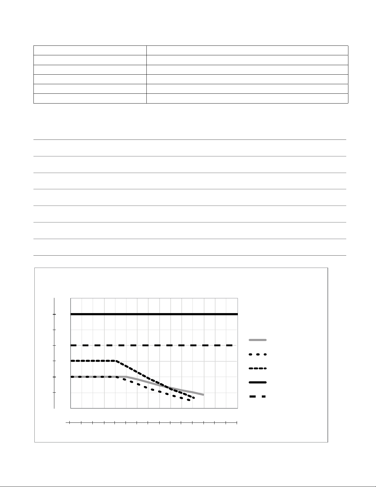
Mechanical (Sensors) (*See graph)
Sensor Pressure Temperature Materials
Graphite contacting
conductivity tower
316 SS contacting
conductivity tower
High pressure tower 0-300 psi (0-20 bar)*
Electrodeless tower
Low pressure manifold
High pressure manifold 0-300 psi (0-20 bar)*
Boiler/condensate
contacting conductivity
0-150 psi up to 100°F (38°C)*
0- 50 psi at 140°F (60°C)
0-150 psi up to 100°F (38°C) *
0- 50 psi at 140°F (60°C)
0-150 psi up to 100°F (38°C)*
0- 50 psi at 140°F (60°C)
0-150 psi up to 100°F (38°C)*
0- 50 psi at 140°F (60°C)
0-250 psi (0-17 bar)
32-140°F *
(0-60°C)
32-140°F *
(0-60°C)
32-158°F *
(0-70°C)
32-140°F *
(0-60°C)
32-140°F *
(0-60°C)
32-158°F *
(0-70°C)
32-401°F
(0-205°C)
GFRPP, Graphite, FKM 3/4” NPTF
GFRPP, 316SS, FKM 3/4” NPTF
316SS, PEEK 3/4” NPTF
PP, PVC, FKM 3/4” NPTF
GFRPP, PVC, FKM,
Isoplast
Carbon steel, steel, brass 3/4” NPTF
316SS, PEEK 3/4” NPTM
Process
Connections
3/4” NPTF
Bar
24.1
20.7
17.2
13.8
10.3
6.9
3.4
PSI
350
300
250
200
150
100
50
Pressure vs. Temperature
pH/ORP
LD2
Cond
HP Cond/Steel
HP pH/ORP/Steel
0
30
-1.1
40
4.4
50
10.0
60
15.5
70
21.1
80
26.6
90
32.2
100
37.7
110
43.3
120
48.8
130
54.4
140
60.0
150
65.5
160
71.1
170
76.6
180
°C
82.2
°F
4
Page 9

2.4 Variables and their Limits
Sensor input settings Low Limit High Limit
Conductivity alarm limits 0 50,000
Conductivity alarm dead band 0 50,000
Cell constant 0.01 10
Smoothing Factor 0% 90%
Comp Factor (conductivity linear ATC only) 0% 20%
Installation Factor (Electrodeless conductivity only) 0.5 1.5
Cable length 0.1 3,000
PPM conversion factor (only if units = PPM) 0.001 10.000
Default temperature -20 500
Calibration Required Alarm 0 days 365 Days
Flow meter input settings Low Limit High Limit
Totalizer alarm 0 100,000,000
Volume/contact for units of Gallons or Liters 1 100,000
Volume/contact for units of m
K Factor for units of Gallons or Liters 0.01 10,000
K Factor for units of m
Paddlewheel rate alarm limits 0 High end of sensor range
Paddlewheel rate alarm deadband 0 High end of sensor range
Smoothing Factor 0% 90%
Set Flow Total 0 1,000,000,000
Relay output settings Low Limit High Limit
Output Limit Time 1 second 86,400 seconds (0 = unlimited)
Hand Time Limit 1 second 86,400 seconds (0 = unlimited)
Min Relay Cycle 0 seconds 300 seconds
Set Point Low end of sensor range High end of sensor range
Duty Cycle Period (On/Off, Dual Set-point modes) 0:00 minutes 59:59 minutes
Duty Cycle (On/Off, Dual Setpoint modes) 0% 100%
Dead Band Low end of sensor range High end of sensor range
Feed duration (Flow timer mode) 0 seconds 86,400 seconds
Accumulator volume (Flow timer mode) 0 1,000,000
Feed Percentage (Bleed then Feed mode) 0% 100%
Feed Lockout Time Limit (Bleed & Feed, Bleed then Feed modes) 0 seconds 86,400 seconds
Prebleed to Conductivity (Biocide mode) 1 (0 = no prebleed) High end of sensor range
Prebleed Time (Biocide mode) 0 seconds 86,400 seconds
Bleed Lockout(Biocide mode) 0 seconds 86,400 seconds
Event duration (Biocide, Timer modes) 0 seconds 86,400 seconds
Proportional band (Time/Pulse Proportional mode, Intermittent
Sampling)
Sample period (Time Proportional mode) 10 seconds 3600 seconds
Sample Time (Intermittent Sampling mode) 0 seconds 3600 seconds
Hold Time (Intermittent Sampling mode) 0 seconds 3600 seconds
Maximum Blowdown (Intermittent Sampling mode) 0 seconds 3600 seconds
Wait Time (Intermittent Sampling mode) 0 seconds 86,400 seconds
Max Rate (Pulse Proportional mode) 10 pulses/minute 480 pulses/minute
Minimum Output (Pulse Proportional mode) 0% 100%
3
3
0.001 1,000
1 100,000
Low end of sensor
High end of sensor range
range
5
Page 10

Maximum Output (Pulse Proportional mode) 0% 100%
Analog (4-20 mA) Output settings Low Limit High Limit
4 mA Value 0 30,000
20 mA Value 0 30,000
Hand Output 0% 100%
Set Point 0 30,000
Proportional Band 0 30,000
Minimum Output 0% 100%
Maximum Output 0% 100%
Off Mode Output (Proportional, PID, Flow Prop modes) 0 mA 21 mA
Pump Capacity (Flow Prop mode) 0 gal/hour or l/hour 10,000 gal/hour or l/hour
Pump Setting (Flow Prop mode) 0% 100%
Specic Gravity (Flow Prop mode) 0 g/ml 9.999 g/ml
Target (Flow Prop mode) 0 ppm 1,000,000 pm
Error Output 0 mA 21 mA
Conguration settings Low Limit High Limit
Local Password 0000 9999
Alarm Delay 0:00 minutes 59:59 minutes
3.0 UNPACKING & INSTALLATION
3.1 Unpacking the unit
Inspect the contents of the carton. Please notify the carrier immediately if there are any signs of damage to the
controller or its parts. Contact your distributor if any of the parts are missing. The carton should contain a W100
series controller and an instruction manual. Any options or accessories will be incorporated as ordered.
3.2 Mounting the electronic enclosure
The controller is supplied with mounting holes on the enclosure. It should be wall mounted with the display at eye level,
on a vibration-free surface, utilizing all four mounting holes for maximum stability. Use M6 (1/4” diameter) fasteners
that are appropriate for the substrate material of the wall. The enclosure is NEMA 4X (IP65) rated. The maximum
operating ambient temperature is 131°F (55°C); this should be considered if installation is in a high temperature
location. The enclosure requires the following clearances:
Top: 2” (50 mm)
Left: 8” (203 mm) (not applicable for prewired models)
Right: 4” (102 mm)
Bottom: 7” (178 mm)
3.3 Installation
Once the controller is mounted, the metering pumps may be located at any distance from the controller.
Plumbing
The W100 series controllers can be supplied with a ow switch manifold designed to provide a continuously owing
sample of cooling water to the sensors. Please refer to Figures 2 through 6 below for some typical installation drawings.
Cooling Towers:
Tap off the discharge side of the recirculation pump to provide a minimum ow of 1 gallon per minute past the sensor.
The sample must ow into the bottom of the manifold in order to close the ow switch, and return to a point of
lower pressure in order to ensure ow. Install an isolation valve on both sides of the manifold to stop ow for
sensor maintenance.
6
Page 11

The contacting conductivity sensor should be placed as close to the controller as possible, to a maximum distance of
250 ft. (76 m). Less than 25 ft. (8 m) is recommended. The cable must be shielded from background electrical noise.
Always route low voltage (sensor) signals with at least a 6” (15 cm) separation from AC voltage wiring.
The electrodeless conductivity sensor should be placed as close to the controller as possible, to a maximum distance
of 120 ft. (37 m). Less than 20 ft. (6 m) is recommended.. The cable must be shielded from background electrical noise.
Always route low voltage (sensor) signals with at least a 6” (15 cm) separation from AC voltage wiring. These sensors
are affected by the geometry and conductivity of their surroundings, so either maintain 6 inches (15 cm) of sample
around the sensor or ensure that any nearby conductive or nonconductive items are consistently positioned. Do not install
the sensor in the path of any electrical current that may be owing in the solution, as this will shift the conductivity reading.
IMPORTANT: To avoid damaging the female pipe threads on the supplied plumbing parts, use no more than 3 wraps
of PTFE tape and thread into the pipe FINGER tight only! DO NOT use any pipe dope, plumber’s putty or other
sealing products that containdiacetone alcohol, as these attack the ow switch plastic! Use PTFE tape ONLY!
Boilers:
The conductivity sensor should be placed as close to the controller as possible, to a maximum distance of 250 ft.
(76m). The cable MUST be shielded from background electrical noise. Use 24 AWG cable.
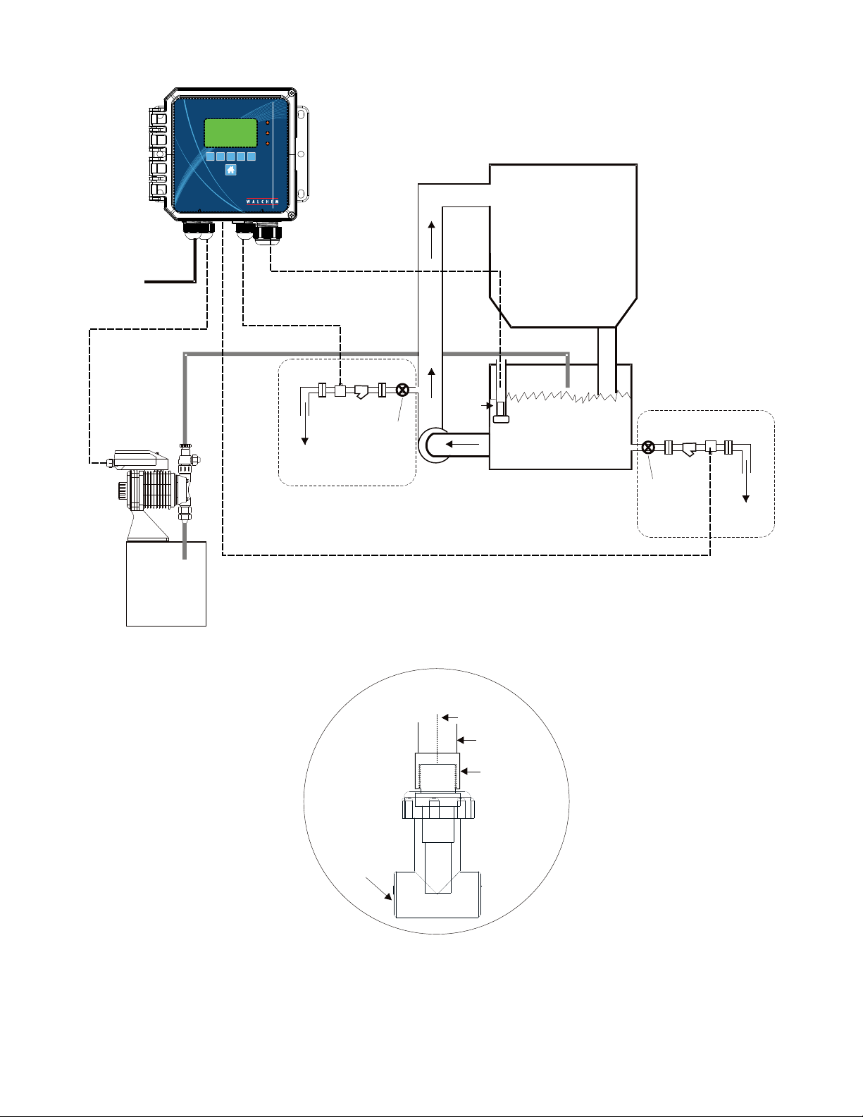
Important Boiler Installation Notes: (see gures 3 and 4)
1. Make sure the minimum water level in the boiler is at least 4-6 inches (10-15 cm) above the skimmer blowdown
line. If the skimmer line is closer to the surface, it is likely that steam will be drawn into the line instead of boiler
water. The skimmer line must also be installed above the highest tube.
2. Maintain a 3/4 inch minimum pipe ID with no ow restrictions from the tap for the boiler skimmer blowdown
line to the electrode. If the ID is reduced below 3/4 inch, then ashing will occur beyond that point and the conductivity reading will be low and erratic. Minimize the usage of tees, valves, elbows or unions between the boiler
and the electrode.
3. A manual shut off valve should be installed so that the electrode can be removed and cleaned. This valve must be
a full port valve in order to avoid a ow restriction.
4. Keep the distance between the tap for the boiler skimmer line to the electrode as short as possible, to a maximum
of 10 feet (3m).
5. Mount the electrode in the side branch of a tee in a horizontal run of pipe. This will minimize entrapment of
steam around the electrode and will allow any solids to pass through.
6. There MUST be a ow restriction after the electrode and/or control valve in order to provide back pressure. This
ow restriction will be either a ow control valve or an orice union. The amount of the ow restriction will
affect the blowdown rate as well, and should be sized accordingly.
7. Install the motorized ball valve or solenoid valve per the manufacturer’s instructions.
For best results, align the hole in the conductivity electrode such that the direction of water ow is through the hole.
Guide to Sizing Blowdown Valves and Orice Plates
1. Determine the Rate of Steam Production in Pounds per Hour:
Either read off the boiler name plate (water-tube boilers) or Calculate from horsepower rating (re-tube boilers):
HP x 34.5 = lbs./hr. Example: 100 HP = 3450 lbs./hr
2. Determine the Concentration Ratio (BASED ON FEEDWATER)
A water treatment chemical specialist should determine the desired number of cycles of concentration. This is the
ratio of TDS in the boiler water to TDS in the feedwater. Note that feedwater means the water that is fed to the
boiler from the deaerator and includes makeup water plus condensate return.
Example: 10 cycles of concentration has been recommended
7
Page 12
3. Determine the Required Blowdown Rate in Pounds Per Hour
Blowdown Rate = Steam Production / (Concentration Ratio –1)
Example: 3450/(10-1) = 383.33 lbs./hr.
4. Determine if Continuous or Intermittent Sampling is Required
Use intermittent sampling when the boiler operation or loading is intermittent, or on boilers where the required
blowdown rate is less than 25% of the smallest available ow control valve or less than the ow through the
smallest orice. See the graphs on the next page.
Use continuous sampling when the boiler is operating 24 hours per day and the required blowdown rate is more
than 25% of the smallest applicable ow control valve or orice. See the graphs on the next page.
Use of a ow control valve will give you the best control of the process, since the ow rate can be easily
adjusted. The dial on the valve also gives you a visual indication if the ow rate has been changed. If the valve
clogs, it can be opened to clear the obstruction, and closed to the previous position.
If an orice plate is used, you must install a valve downstream from the orice in order to ne tune the ow
rate and provide additional back pressure in many applications.
Example: An 80 psi boiler has a Required Blowdown Rate of 383.33 lbs./hr. The maximum ow rate of the
smallest ow control valve is 3250 lbs./hr. 3250 x 0.25= 812.5 which is too high for continuous sampling.
Using an orice, the ow rate through the smallest diameter plate is 1275 lbs./hr. This is too high for continuous
sampling.
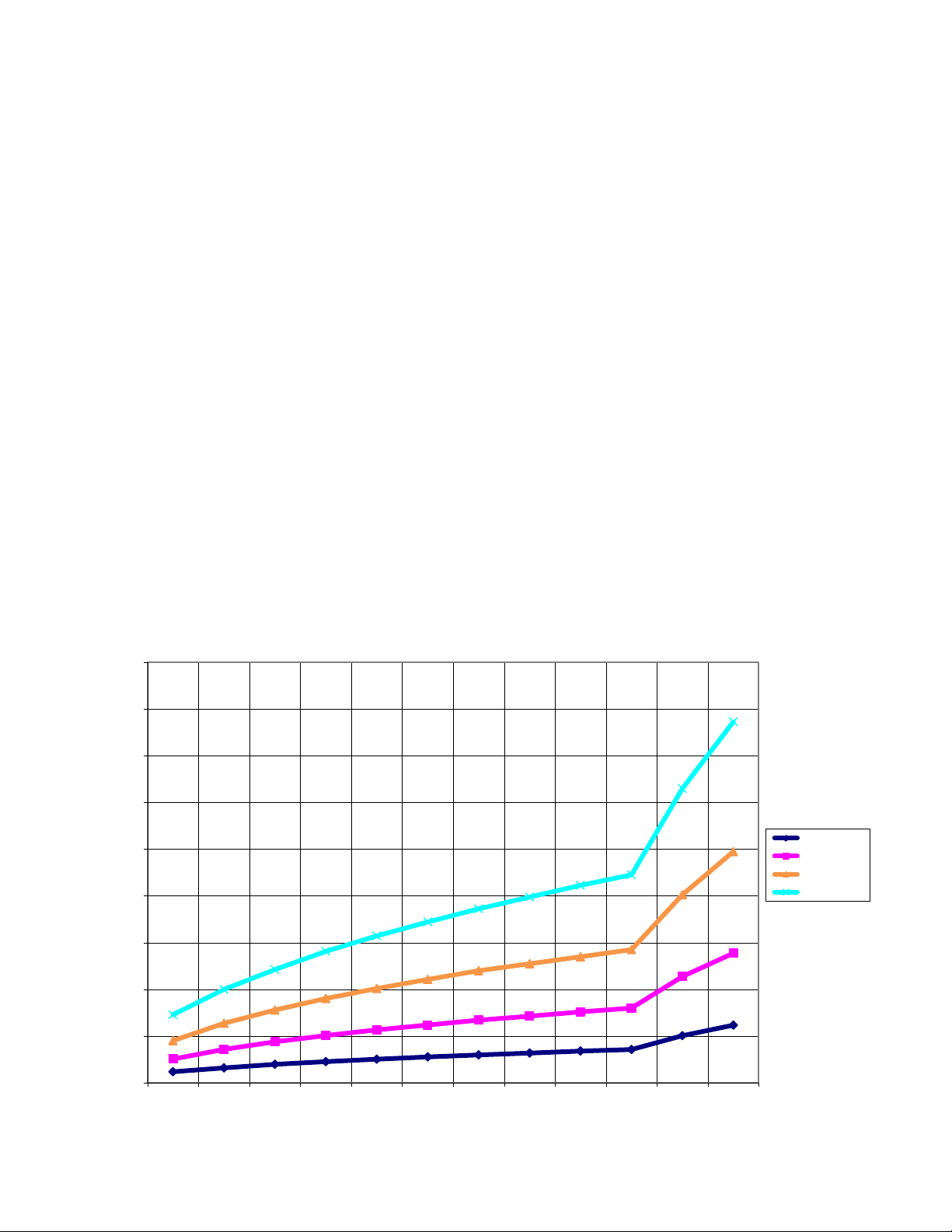
5. Determine the Orice or Flow Control Valve Size for this Blowdown Rate
Use the following graphs to select a ow control device:
Flow Rate in Lbs/hr for Various Orifices
18000
16000
14000
12000
10000
lbs/hr
8000
6000
1/8 inch dia
3/16 inch dia
1/4 inch dia
5/16 inch dia
4000
2000
0
10 20 30 40 50 60 70 80 90 100 200 300
Pressure PSI
8
Page 13
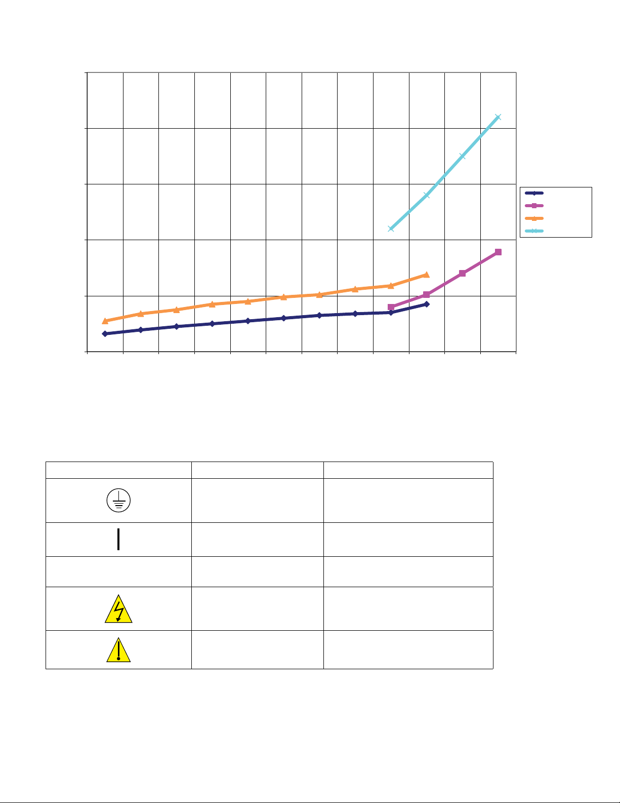
25000
20000
Flow Control Valve
Maximum Flow Rates in Lbs/hr
15000
lbs/hr
10000
5000
0
20 30 40 50 60 70 80 90 100 150 200 300
3.4 IconDenitions
Symbol Publication Description
1/2" 150 PSI
1/2" 300 PSI
3/4" 150 PSI
3/4" 300 PSI
Pressure PSI
O
IEC 417, No.5019 Protective Conductor Terminal
IEC 417, No. 5007 On (Supply)
IEC 417, No. 5008 Off (Supply)
ISO 3864, No. B.3.6 Caution, risk of electric shock
ISO 3864, No. B.3.1 Caution
9
Page 14
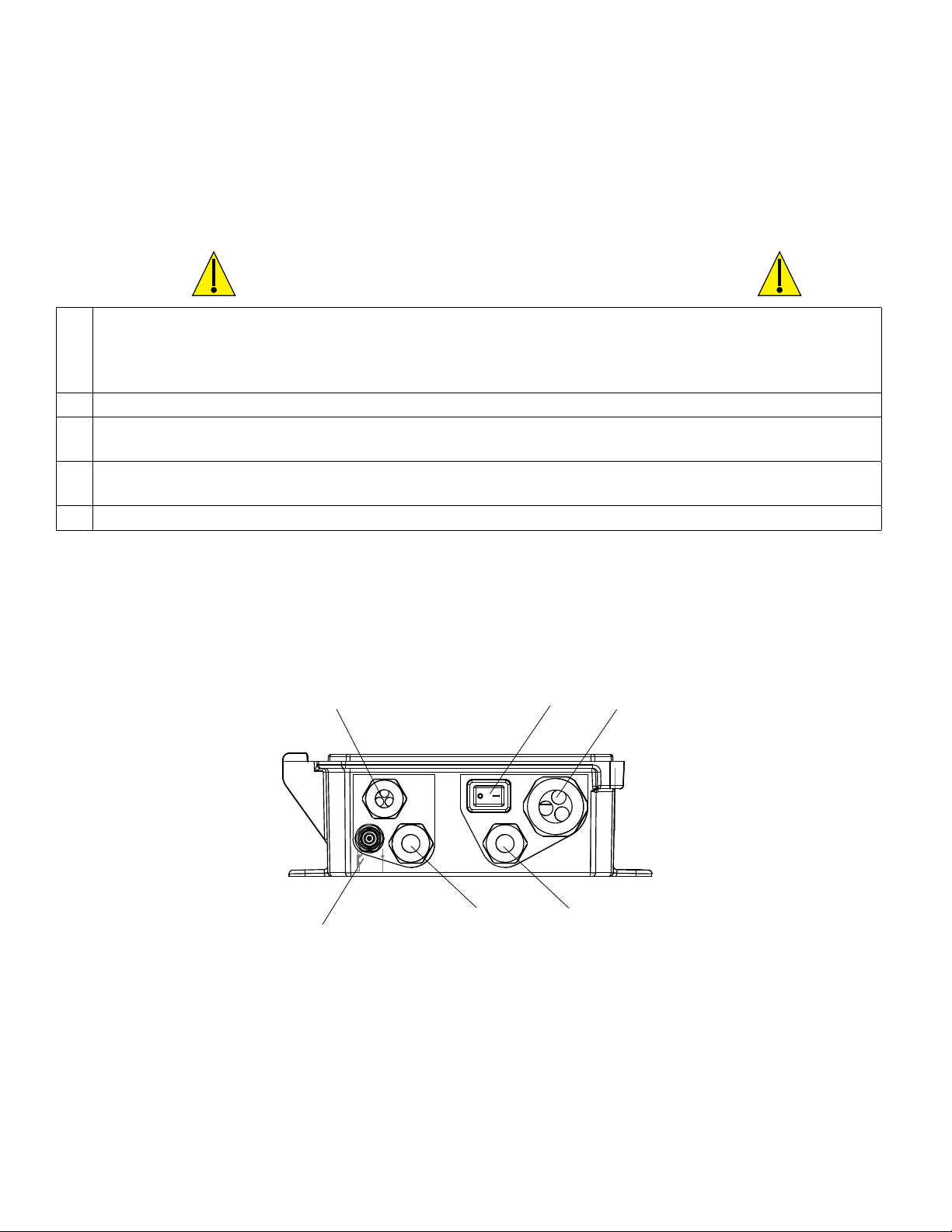
3.5 Electrical installation
The various standard wiring options are shown in gure 1 below. Your controller will arrive from the factory prewired
or ready for hardwiring. Depending on your conguration of controller options, you may be required to hardwire some
or all of the input/output devices. Refer to gures 7 through 13 for circuit board layout and wiring.
Note: when wiring the optional ow meter contactor input, the 4-20 mA outputs or a remote ow switch, it is advisable
to use stranded, twisted, shielded pair wire between 22-26 AWG. Shield should be terminated at the controller (see
gure 10).
CAUTION
1. There are live circuits inside the controller even when the power switch on the front panel is in the OFF position!
The front panel must never be opened before power to the controller is REMOVED!
If your controller is prewired, it is supplied with a 8 foot, 18 AWG power cord with USA style plug. A tool (#1
Phillips driver) is required to open the front panel.
2. When mounting the controller, make sure there is clear access to the disconnecting device!
3. The electrical installation of the controller must be done by trained personnel only and conform to all applicable
National, State and Local codes!
4. Proper grounding of this product is required. Any attempt to bypass the grounding will compromise the safety of
persons and property.
5. Operating this product in a manner not specied by Walchem may impair the protection provided by the equipment.
Digital Inputs
& Analog Output
Optional pH/ORP/ISE
Sensor BNC
Figure 1 Conduit Wiring
Sensor
Power
Switch
Relay
Outputs
AC Power
10
Page 15

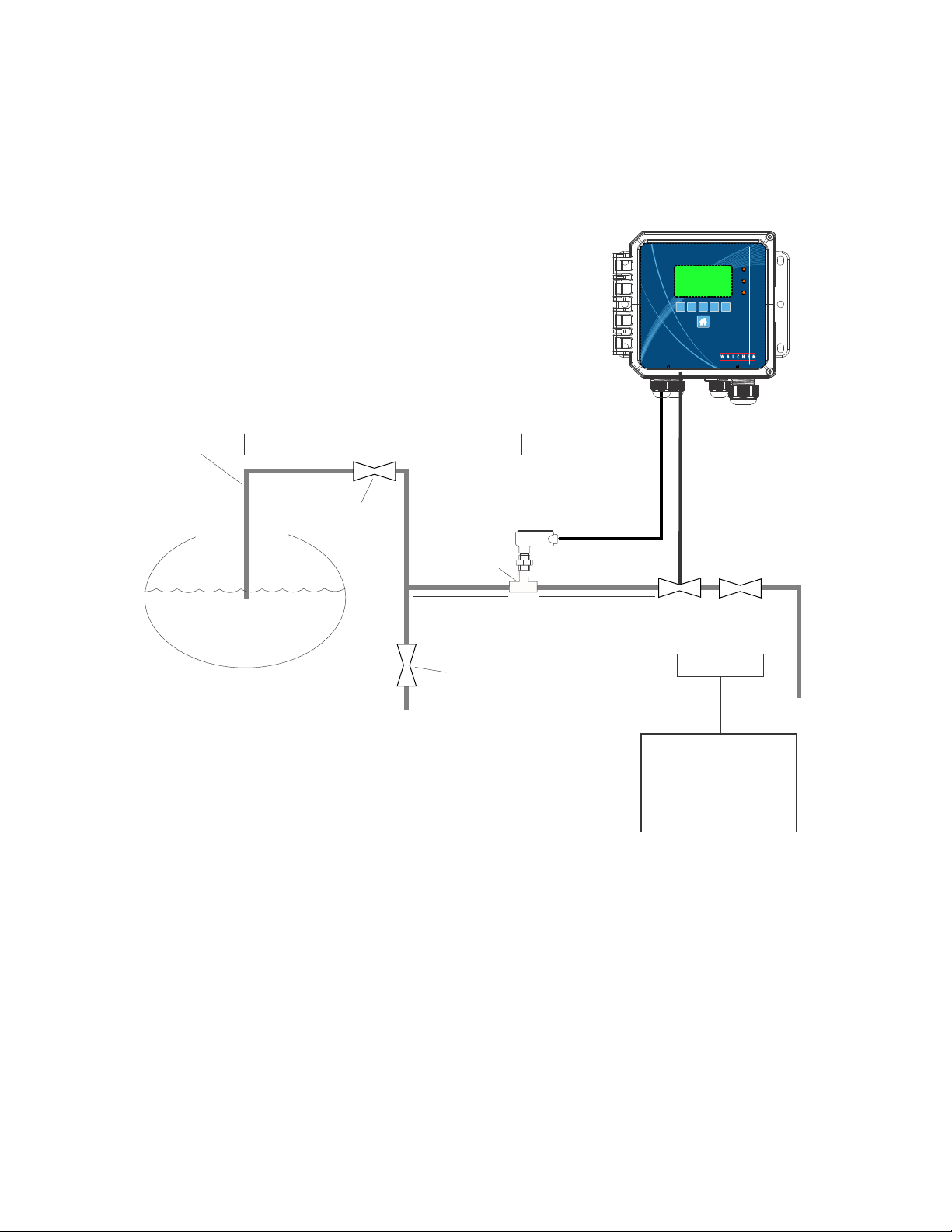
HEAT
EXCHANGER
�METERING
PUMPS
COOLING TOWER
13"
11.75"
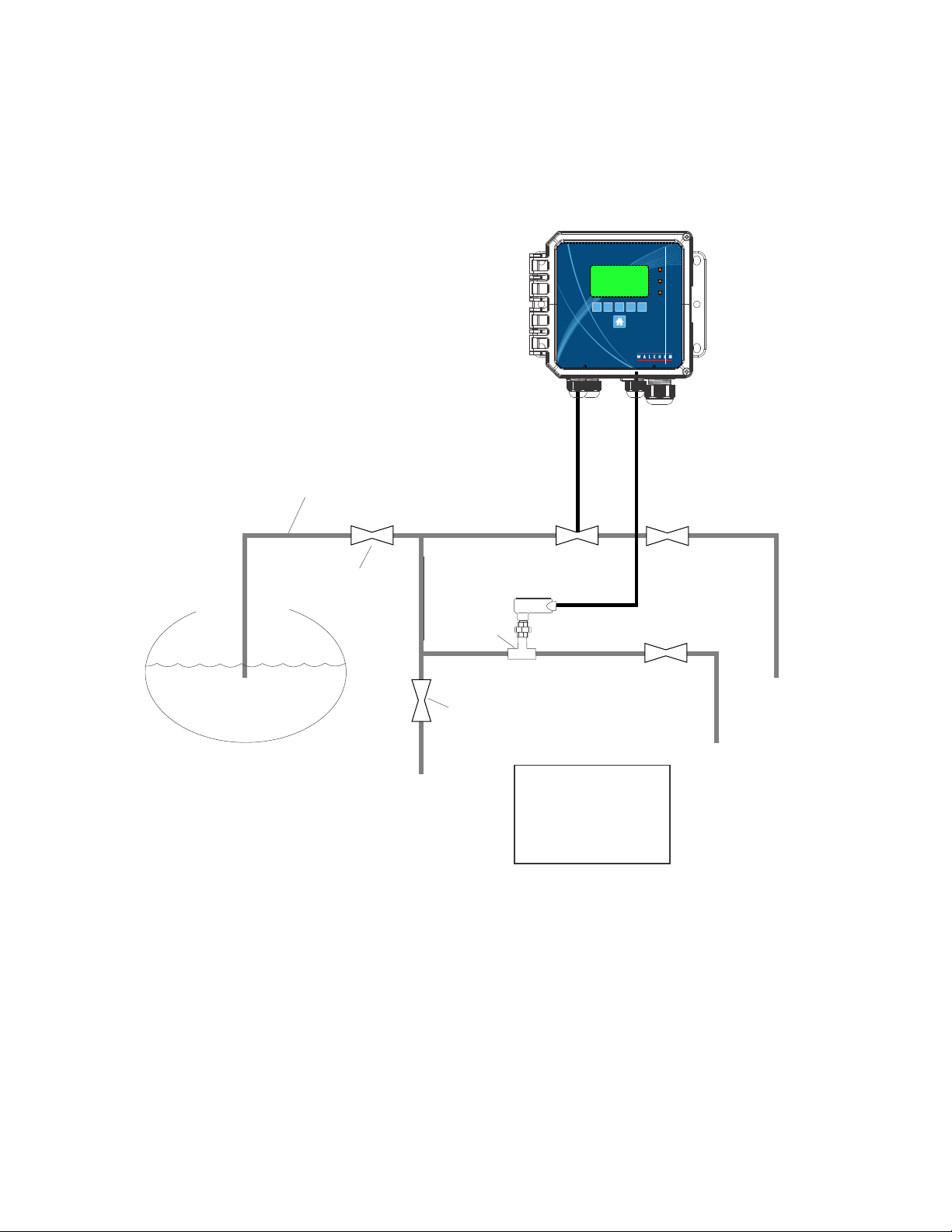
Figure 2 Typical Cooling Tower Installation
11
Page 16
1
2
3
Skimmer Blowdown Line
3/4" Min. up to Electrode
with minimal valves, elbows & unions
10 ft. max.
Full Port Block
Valve
TO
DRAIN
¾" TEE
2 ft.
minimum
Manual Blowdown
(Normally Closed)
CONDUCTIVITY
ELECTRODE
1 to 3 ft.
maximum
Motorized
Ball
or Solenoid
Valve
Flow
Control
Valve or
Orifice Union
To Drain
Install accessories
either vertically or
horizontally, per
manufacturer's
instructions.
Figure 3 Typical Boiler Installation Intermittent Sampling
12
Page 17
1
2
3
Skimmer Blowdown Line
3/4" Min. up to Electrode
Full Port Block
Valve
To Drain
Motorized
Ball
or
Solenoid
Valve
CONDUCTIVITY
ELECTRODE
¾" TEE
Manual Blowdown
(Normally Closed)
Install accessories
either vertically or
horizontally, per
manufacturer's
instructions.
Flow
Control
Valve
or Orifice
Union
Flow
Control
Valve or
Orifice Union
To Drain
To Drain
Figure 4 Typical Boiler Installation Continuous Sampling
13
Page 18
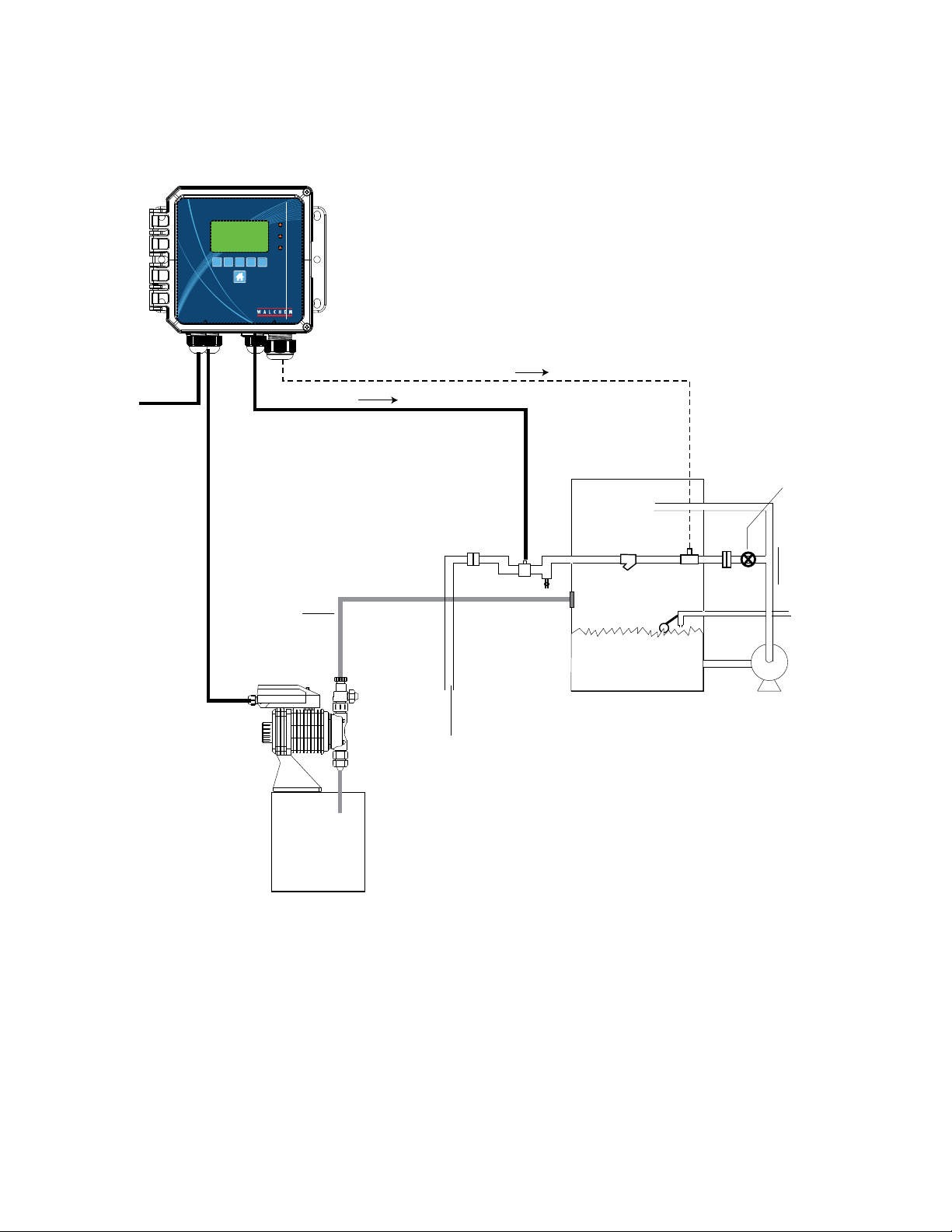
TO
110 VOLT AC
OUTLET
1
2
3
TYPICAL INSTALLATION
SUBMERSION ELECTRODE
COOLING
TOWER
CHEMICAL
PUMP
CHEMICAL
TANK
XYZX
VALV E
TO
SANITARY
SEWER
(OPTION "A")
CIRCULATION
PUMP
(X) Unions; installed for replacement of
solenoid or strainer
(Y) ½" Y-strainer
(Z) ½"solenoid
DETAIL OF
PROBE ASSEMBLY
CLIP PROBE
ASSEMBLY TO
SUMP WALL FOR
EASY REMOVAL
FOR CLEANING
PROBE
TO
CONTROLLER
1" PVC
1" NPTF PVC
COUPLING
(OPTION "B")
OPEN
SUMP
X Y Z X
VALV E
TO
SANITARY
SEWER
NOTE: LOCATION OF SOLENOID VALVE
USING OPTION "A" OR OPTION "B"
DEPENDS ON SYSTEM CONFIGURATION.
PIPE
INSTALL APPROXIMATELY
HALF-WAY IN SUMP VOLUME
AVOID INSTALLATION NEAR
PUMP SUCTION INLET
¾" PROBE
IN TEE
Figure 5 Typical Cooling Tower Installation Submersion Sensor
14
Page 19
TO
CONSTANT
110 VOLTS
1
2
3
TYPICAL INSTALLATION
INTERMITTENT SAMPLING
TO ELECTRODE
TO SOLENOID
SHUTOFF
VALV E
PE DISCHARGE
CHEMICAL
PUMP
TUBING
CHEMICAL
TANK
(A)
TO
SANITARY
SEWER
(A)
(D)
(B)
(F)
(C)
(E)
SPRAY TOWER
(A) Unions; installed for replacement of
solenoid, strainer or probe
(B) ½" solenoid
(C) ½" Y-strainer
(D) Conductivity sensor in ¾" NPTF tee
(supplied with controller)
(E) ½" PVC bulkhead fitting
(F) winter drain
CITY WATER
MAKEUP
SPRAY
PUMP
Figure 6 Typical Cooling Tower Installation Intermittent Sampling
15
Page 20

RELAY OUTPUT
CONNECTOR
TERMINAL BLOCK
EARTH GROUND
TERMINAL BLOCK
POWER SUPPLY
DIGITAL INPUT & OPTIONAL
ANALOG OUTPUT TERMINAL BLOCK
POWER
TB3
1234567891011
SWITCH
TB6
12
R1
R2
NNN
TB4
TB2
1234567891011
R3
FUSE
POWER
SWITCH
FUSE
N
L
TB5
TB1
12
pH
–
+
TB7
SENSOR INPUT
AC POWER
TERMINAL
BLOCK
TERMINAL BLOCK
OPTIONAL NON-AMPLIFIED
PH/ORP INPUT TERMINAL
BLOCK
RIBBON CABLE
Figure7IdenticationofParts
16
MAIN CONTROLLER
BOARD
USB
Page 21

TB7
1
2
3
4
5
6
7
8
9
TB3
10
11
12
TB2
1
2
3
4
5
6
TB4
7
8
9
10
11
TB5
12
TB1
+
pH
–
TB6
R1
R2
N
N
N
R3
N
L
FUSE
POWER
SWITCH
POWER
SWITCH
TB1 ECOND CCOND
XMT+ XMT
1
2
XMT–
3 X-SHLD
pH/ORP
SHIELD SHIELD SHIELD
4
5 RCV–
6 RCV+
7 RCV IN+
8 –5V
w/BNC
USE
BNC
FOR
INPUT
SIGNAL
pH/ORP
DIS
+5V
9 TEMP– TEMP– TEMP– TEMP–
10 TEMP+ TEMP+ TEMP+ TEMP+
11 IN–
R-SHLD
12
SAFETY COVER LABEL
TB2 FUNCTION
1 4-20 OUT–
2 4-20 OUT+
3 SHIELD
4
DIG IN 2–
5 DIG IN 2+
6 +9 VDC
7 SHIELD
8
DIG IN 1–
9 DIG IN 1+
+9 VDC
10
11 SHIELD
12
10
11
12
1
2
3
XMT RED
SHIELD
4
5
6
7
8
9
RCV BLK
TEMP– WHT
TEMP+ GRN
TB1
WHT
RED
BLK
GRN
High Pressure
Conductivity
Electrode
Condensate
Electrode
(wiring is typical of all three sensor options)
Figure 8 Contacting Conductivity Sensor Input Wiring
17
Conductivity
Electrode
Page 22

pH/ORP
TB1 ECOND CCOND
w/BNC
pH/ORP
DIS
1 XMT+ XMT
2
XMT–
3 X-SHLD
4 +5V
5 RCV–
6 RCV+
7 RCV IN+
8 –5V
SHIELD SHIELD SHIELD
USE
BNC
FOR
INPUT
SIGNAL
9 TEMP– TEMP– TEMP– TEMP–
10
TEMP+ TEMP+ TEMP+ TEMP+
11 IN–
R-SHLD
12
TB2 FUNCTION
1 4-20 OUT–
2 4-20 OUT+
3 SHIELD
4
DIG IN 2–
5 DIG IN 2+
6 +9 VDC
7 SHIELD
8
DIG IN 1–
9 DIG IN 1+
10
+9 VDC
11 SHIELD
12
10
11
12
1
2
3
4
5
6
7
8
9
TB3
10
11
12
TB2
1
2
3
4
5
6
TB4
7
8
9
10
11
TB5
TB7
1
2
3
4
5
6
12
TB1
+
pH
–
XMT + WHT
XMT – BLK
X-SHLD
RCV – BLK
RCV + RED
TB6
N
N
N
N
L
FUSE
R1
R2
R3
POWER
SWITCH
POWER
SWITCH
7
8
9
TEMP - BLK
TEMP + GRN
R-SHLD
SAFETY COVER LABEL
Figure 9 Electrodeless Conductivity Sensor Input Wiring
TB1
18
Page 23

TB7
1
2
3
4
5
6
7
8
9
TB3
10
11
12
TB2
1
2
3
4
5
6
TB4
7
8
9
10
11
TB5
12
TB1
+
pH
–
TB6
R1
R2
N
N
N
N
L
R3
FUSE
POWER
SWITCH
POWER
SWITCH
–
+
SHIELD
TB1 ECOND CCOND
1
XMT+ XMT
2
XMT–
3
SHIELD SHIELD SHIELD
X-SHLD
pH/ORP
4
5 RCV–
6 RCV+
7 RCV IN+
8 –5V
SIGNAL
w/BNC
USE
BNC
FOR
INPUT
pH/ORP
+5V
9 TEMP– TEMP– TEMP– TEMP–
10
TEMP+ TEMP+ TEMP+ TEMP+
11
R-SHLD
12
TB2 FUNCTION
DIS
IN–
1
4-20 OUT–
2 4-20 OUT+
3 SHIELD
DIG IN 2–
4
5 DIG IN 2+
6 +9 VDC
7 SHIELD
8
DIG IN 1–
9 DIG IN 1+
10
+9 VDC
11 SHIELD
12
10
11
12
Chart
Recorder
1
2
3
4
5
6
7
INPUT –
SIGNAL +
POWER
SHIELD
8
9
SHIELD
TB2
Hall Effect
Flow Meter
Reed Switch, Relay
(Flow Switch, Water Meter)
Polarity not critical
Figure 10 Digital Input and Analog Output Wiring
19
Page 24

TB3
GRN 120V
GRN/YEL 240V
GRN 120V
GRN/YEL 240V
GRN 120V
GRN/YEL 240V
TB7
1
2
3
4
5
6
7
8
9
TB3
10
11
12
TB2
1
2
3
4
5
6
TB4
TB5
N
N
N
N
L
7
8
9
10
11
12
TB1
+
pH
–
IF MOTORIZED BALL VALVE
POWER
R1
R2
R3
POWER
SWITCH
SWITCH
TB6
NC
NO
NC
NO
N
NC
N
NO
N
N
L
FUSE
GRN 120V
TB5
GRN/YEL 240V
N
L
TB4
N
N
N
WHT 120V
BLU 240V
BLK 120V
BRN 240V
WHT 120V
BLU 240V
WHT 120V
BLU 240V
WHT 120V
BLU 240V
SOLENOID/
MOTORIZED
BALL VALVE
PUMP
ALARM
BLK 120V
BRN 240V
BLK 120V
BRN 240V
BLK 120V
BRN 240V
NC
NO
NC
NO
NC
NO
TB6
R1
R2
R3
Power Supply
(120 VAC or 240 VAC)
Figure 11 W100 AC Power & Relay Output Wiring
20
Page 25

TB3
Fused
External
Power
Source
GRN 120V
GRN/YEL 240V
WHT 120V
BLU 240V
TB7
1
2
3
4
5
6
7
8
9
TB3
10
11
12
TB2
1
2
3
4
5
6
TB4
7
8
9
10
11
TB5
12
TB1
+
pH
–
TB6
N
N
N
N
N
L
L
FUSE
R1
R2
R3
POWER
SWITCH
POWER
SWITCH
PLC
R1
GRN 120V
TB5
GRN/YEL 240V
N
L
Fused
External
Power
Source
WHT 120V
BLU 240V
BLK 120V
BRN 240V
GRN 120V
GRN/YEL 240V
WHT 120V
BLU 240V
Power Supply
(120 VAC or 240 VAC)
PUMP
ALARM
BLK 120V
BRN 240V
BLK 120V
BRN 240V
BLK 120V
BRN 240V
BLK 120V
BRN 240V
R2
R3
TB6
Figure 12 W110 AC Power & Relay Output Wiring
21
Page 26

4.0 FUNCTION OVERVIEW
4.1 Front Panel
Figure 13 Front Panel
4.2 Display
A Home screen is displayed while the controller is on. This display shows the sensor readings, active alarms and a row
of icons that are used to navigate to other screens.
4.3 Keypad
The keypad consists of 5 ATM type keys and a Home key used to return to the summary screen. The icon above the
ATM keys will dene its purpose on the current screen being displayed.
4.4 Icons
The following icons appear on the Home screen. Press the key below the icon to get to the main menu selections.
Alarm Menu
Inputs Menu
Outputs Menu
Conguration/Settings Menu
22
Page 27

Other icons may appear in the menu screens.
X
Alarm Menu
Inputs Menu
Outputs Menu
Conguration/Settings Menu
Calibration key appears in sensor input menus and brings up the calibration menu
Cancel key cancels any entry
The Page Down icon scrolls down to a new page in a list of options.
The Page Up icon scrolls up to a new page in a list of options.
The Conrm icon accepts a choice and advances to the next calibration step
The Back/Return icon returns the display to the previous screen
The Make Character Higher key is used when making an alphanumeric entry
The Make Character Lower key is used when making an alphanumeric entry
The Move Cursor key is used to scroll left to right within an alphanumeric entry
The ENTER key is used to nish entering data or enter a highlighted menu choice
Overview of the use of keys
Changing Numeric Values
To change a number, use the Move Cursor key to the digit to be changed. If the new number will be negative, start
with the sign using the Make Character Higher key. Move the cursor to each digit and change the value using either
the Make Character Higher or Lower keys. Once the value of the number is correct use the Enter key to store the new
value into memory, or use the Cancel key to leave the number at its previous value and go back.
Changing Names
To change the name used to identify an input or output, use the Move Cursor key to the character to be changed and
change it using either the Make Character Higher or Lower keys. Upper case and lower case letter, numbers, a blank
space, period, plus and minus symbols are available. Move the cursor to the right and modify each character. Once
the word is correct, use the Enter key to store the new value into memory, or use the Cancel key to leave the word at
its previous value and go back.
23
Page 28

Choosing from a List
Selecting the type of sensor, the units of measure of an input, or the control mode used for an output, the selection is
picked from a list of available options. Use the Page Up or Down keys to highlight the desired option, and then use
the Enter key to store the new option into memory, or use the Return key to leave the option at its previous value and
go back.
Hand-Off-Auto Relay Mode
Use the Left or Right Move Cursor keys to highlight the desired relay mode. In Hand mode the relay is forced on for
a specied amount of time and when that time is up the relay returns to its previous mode, in Off mode the relay is
always off until taken out of Off mode, and in Auto mode the relay is responding to control set points. Use the Conrm
key to accept the option, or the Return key to leave the option at its previous value and go back.
Interlock and Force On Menus
To select which outputs to force on, or which outputs to be interlocked, use the Move Cursor key to highlight the output
to be selected, then use the Make Character Higher or Lower keys to check or uncheck that output. When nished, press
the Conrm key to accept the changes or the Cancel key to leave the selections at the previous settings and go back.
4.5 Startup
Initial Startup
After having mounted the enclosure and wired the unit, the controller is ready to be started. Plug in the controller and
turn on the power switch to supply power to the unit. The display will briey show the model number and then revert
to the normal summary display. Press the Home key if necessary to get to the Home screen. Refer to section 5 below
for more details on each of the settings.
Settings Menu (see section 5.4)
Choose language
Press the Conguration Settings key. Press the Enter key. Press the Scroll Down key until the English word “Language”
is highlighted. Press the Enter key. Press the Scroll Down key until your language is highlighted. Press the Conrm key
to change all menus to your language.
Set date (if necessary)
Press the Scroll Up key until Date is highlighted. Press the Enter key. Press the Move Cursor key to highlight the
Day, and then use the Make Character Higher or Lower keys to change the date. Press the Conrm key to accept the
change.
Set time (if necessary)
Press the Scroll Down key until Time is highlighted. Press the Enter key. Press the Move Cursor key to highlight the
HH (hour) and/or MM (minute), then use the Make Character Higher or Lower keys to change the time. Press the Con-
rm key to accept the change.
Set global units of measure
Press the Scroll Down key until Global Units is highlighted. Press the Enter key. Press the Scroll Down key until the
desired units is highlighted. Press the Conrm key to accept the change.
Set temperature units of measure
Press the Scroll Down key until Temp Units is highlighted. Press the Enter key. Press the Scroll Down key until the
desired units is highlighted. Press the Conrm key to accept the change.
Press the Home key. Press the Inputs key.
24
Page 29

CONFIG
Alarms (1)
Sensor (S1)
Temp (S2)
CONFIG
Global Settings
Security Settings
>
>
Additional Config Settings:
Display Settings
File Utilities
Controller Details
Config > Global Settings
Date 2017-Mar-22
Time 15:49:16
>
>
Config > Security Settings
Controller Log Out
Security
>
>
Config > Display Settings
Home 1
Home 2
>
>
Additional Global Settings:
Global Units
Temperature Units
Alarm Delay
HVAC Modes
Language
Additional Security Settings:
Local Password
Additional Display Settings:
Adjust Display
Key Beep
Config > File Utilities
File Transfer Status
Export Event Log
>
>
Config > Controller Details
Controller
Product Name
>
>
25
Additional File Utilities:
Import User Config File
Export User Config File
Export System Log
Restore Default Config
Software Upgrade
Additional Controller Details:
Control Board
Software Version
Sensor Board
Software Version
Power Board
Battery Power
Internal Temp 1
Internal Temp 2
Page 30

Inputs
CCond (S1) 0 µS/cm
INPUTS
Temp (S2) 74.7 °F
>
>
> > CCond (S1) > Calibration
One Point Process Calibration
(All)
One Point Buffer Calibration (CCond,ECond,pH,ORP,Generic)
Two Point Buffer Calibration (ECond,pH,ORP,Generic)
Three Point Buffer Calibration (pH)
Open Air Calibration
(Cond)
Zero Calibration (Disinfection,Linear Generic)
>
>
No Alarms (1)
CCond (S1) 0 µS/cm
Temp (S2) 74.7°F
Inputs>CCond (S1)
Details Screen
Content varies with
output type
>
>>CCond (S1)
Alarms
Deadband
>
>>ECond (S1)
Alarms
Deadband
>
>>Temperature (S2)
Alarms
Deadband
>
>>pH (S1)
Alarms
Deadband
>
>>ORP (S1)
Alarms
Deadband
>
Additional Settings for CCond:
Reset Calibration Values
Cal Required Alarm
Alarm Suppression
Smoothing Factor
Default Temp
Temp Compensation
Temp Comp Factor
Additional Settings for ECond:
Reset Calibration Values
Cal Required Alarm
Alarm Suppression
Smoothing Factor
Default Temp
Installation Factor
Range
Temp Compensation
Additional Settings for Temperature:
Reset Calibration Values
Cal Required Alarm
Alarm Suppression
Smoothing Factor
Name
Element
Additional Settings for pH:
Reset Calibration Values
Cal Required Alarm
Alarm Suppression
Smoothing Factor
Buffers
Default Temp
Additional Settings for ORP:
Reset Calibration Values
Cal Required Alarm
Alarm Suppression
Smoothing Factor
Default Temp
Cable Length
Cell Constant
Cable Length
Gauge
Units
Name
Type
Temp Comp Factor
Cell Constant
Cable Length
Gauge
Units
Name
Type
Cable Length
Gauge
Electrode
Name
Type
Gauge
Name
Type
>>Generic (S1)
Alarms
Deadband
>
>>DI State (D1-D2)
Open Message
Closed Message
>
Contactor Type
>>Flowmeter (D1-D2)
Totalizer Alarm
Reset Flow Total
>
Paddlewheel Type
>>Flowmeter (D1-D2)
Alarms
Deadband
>
Additional Settings for Generic:
Reset Calibration Values
Cal Required Alarm
Alarm Suppression
Smoothing Factor
Sensor Slope
Sensor Offset
Low Range
High Range
Additional Settings for DI State:
Interlock
Alarm
Total Time
Reset Total Time
Name
Type
Additional Settings for Flowmeter:
Set Flow Total
Scheduled Reset
Volume/Contact
Flow Units
Name
Type
Additional Settings for Flowmeter:
Totalizer Alarm
Reset Flow Total
Set Flow Total
Scheduled Reset
K Factor
Flow Units
Rate Units
Smoothing Factor
Name
Type
Cable Length
Gauge
Units
Electrode (Linear or
Ion Selective)
Name
Type
Only Available in some models
>>Disinfection (S1)
Alarms
Deadband
>
Additional Settings for Disinfection:
Reset Calibration Values
Cal Required Alarm
Alarm Suppression
Smoothing Factor
Cable Length
Gauge
Sensor
Name
Type
26
Page 31

>>On/Off (R1)>Settings
HOA Setting
Setpoint
Outputs>On/Off (R1)
Details Screen
Content varies with
output type
>
Outputs
On/Off (R1) Off
Bleed (R2) Off
>
>
OUTPUTS
R1-R3
Only if HVAC mode is disabled
No Alarms (1)
CCond (S1) 0 µS/cm
Temp (S2) 74.7°F
>
>>Flow Timer (R1)
HOA Setting
Feed Duration
>
>>Bleed and Feed (R1)
HOA Setting
Feed Time Limit
>
>>Bleed then Feed (R1)
HOA Setting
Feed Percentage
>
>>Percent Timer(R1)
HOA Setting
Sample Period
>
>>Biocide Timer (R1)
HOA Setting
Bleed
>
>>Alarm (R1)
HOA Setting
Alarm Mode
>
Only if HVAC mode is enabled
Only if HVAC mode is enabled
Only if HVAC mode is enabled
>>Time Prop (R1)
HOA Setting
Setpoint
>
>>Int Sampling (R1)
HOA Setting
Setpoint
>
>>Manual (R1)
HOA Setting
Interlock Channels
>
>>Pulse Prop (R1)
HOA Setting
Setpoint
>
>>Dual Setpoint (R1)
HOA Setting
Setpoint
>
>>Probe Wash (R1)
HOA Setting
Input
>
>>Timer (R1)
>
HOA Setting
Add Last Missed
Only if HVAC mode is enabled
Only if model W120/power relay bd installed
Additional Settings for On/OFF:
Deadband
Duty Cycle Period
Duty Cycle
Output Time Limit
Reset Output Timeout
Interlock Channels
Activate with Channels
Min Relay Cycle
Hand Time Limit
Reset Time Total
Input
Direction
Name
Mode
Additional Settings for Flow Timer:
Accumulated Volume
Reset Timer
Reset Output Timeout
Interlock Channels
Activate with Channels
Min Relay Cycle
Hand Time Limit
Reset Time Total
Flow Input
Name
Mode
Additional Settings for Bleed and Feed:
Output Time Limit
Reset Output Timeout
Interlock Channels
Activate with Channels
Min Relay Cycle
Hand Time Limit
Reset Time Total
Bleed
Name
Mode
Additional Settings for Bleed then Feed:
Feed Time Limit
Reset Timer
Reset Output Timeout
Interlock Channels
Activate with Channels
Min Relay Cycle
Hand Time Limit
Reset Time Total
Bleed
Name
Mode
Additional Settings for Percent Timer:
Feed Percentage
Interlock Channels
Activate with Channels
Min Relay Cycle
Hand Time Limit
Reset Time Total
Name
Mode
Additional Settings for Biocide Timer:
Event 1 (through 10)
Repetition
Week
Day
Start Time
Duration
Prebleed Time
Prebleed To
Cond Input
Bleed Lockout
Add Last Missed
Interlock Channels
Activate with Channels
Min Relay Cycle
Hand Time Limit
Reset Time Total
Name
Mode
Additional Settings for Alarm:
Output
Interlock Channels
Activate with Channels
Min Relay Cycle
Hand Time Limit
Reset Time Total
Name
Mode
Additional Settings for Time Prop:
Proportional Band
Sample Period
Output Time Limit
Reset Output Timeout
Interlock Channels
Activate with Channels
Min Relay Cycle
Hand Time Limit
Reset Time Total
Input
Direction
Name
Mode
Additional Settings for Int Sampling:
Proportional Band
Deadband
Sample Time
Hold Time
Maximum Blowdown
Wait Time
Trap Sample
Output Time Limit
Reset Output Timeout
Interlock Channels
Activate with Channels
Min Relay Cycle
Hand Time Limit
Reset Time Total
Cond Input
Name
Mode
Additional Settings for Manual:
Min Relay Cycle
Hand Time Limit
Reset Time Total
Name
Mode
Additional Settings for Pulse Prop:
Proportional Band
Min Output
Max Output
Max Rate
Output Time Limit
Reset Output Timeout
Interlock Channels
Activate with Channels
Min Relay Cycle
Hand Time Limit
Reset Time Total
Input
Direction
Name
Mode
Additional Settings for Dual Setpoint:
Set Point 2
Deadband
Duty Cycle Period
Duty Cycle
Output Time Limit
Reset Output Timeout
Interlock Channels
Activate with Channels
Min Relay Cycle
Hand Time Limit
Reset Time Total
Input
Direction
Name
Mode
Additional Settings for Probe Wash:
Input 2
Event 1 (through 10)
Repetition
Week, Day
Events per Day
Start Time
Duration
Sensor Mode
Hold Time
Interlock Channels
Activate with Channels
Min Relay Cycle
Hand Time Limit
Reset Time Total
Name
Mode
Additional Settings for Timer:
Event 1 (through 10)
Repetition
Week, Day
Events per Day
Start Time
Duration
Interlock Channels
Activate with Channels
Min Relay Cycle
Hand Time Limit
Reset Time Total
Name
Mode
27
Page 32

OUTPUT
A1
Output>Retrans (A1)
Details on this page
vary with type of
output
>
Output
On/Off (R1) Off
Retrans (A1) 0.0%
>
>
No Alarms (1)
CCond (S1) 0 µS/cm
Temp (S2) 74.7°F
>>Retransmit (A1)
HOA Setting
4 mA Value
>
>>Proportional (A1)
HOA Setting
Setpoint
>
Only available if HVAC is disabled
>>PID (A1)
HOA Setting
Setpoint
>
Additional Settings for Retransmit:
20 mA Value
Hand Output
Interlock Channels
Error Output
Reset Time Total
Input
Name
Mode
Additional Settings for Proportional:
Proportional Band
Min Output
Max Output
Output Time Limit
Reset Output Timeout
Interlock Channels
Activate with Channels
Hand Output
Hand Time Limit
Reset Time Total
Off Mode Output
Error Output
Input
Direction
Name
Mode
Additional Settings for PID:
Gain
Proportional Gain
Integral Time
Integral Gain
Derivative Time
Derivative Gain
Reset PID Integral
Min Output
Max Output
Max Rate
Output Time Limit
Reset Output Timeout
Interlock Channels
Activate with Channels
Hand Output
Hand Time Limit
Off Mode Output
Error Output
Reset Time Total
Input
Direction
Input Min
Input Max
Gain Form
Name
Mode
>>Manual (A1)
HOA Setting
Interlock Channels
>
>>Flow Prop (A1)
HOA Setting
Target
>
Additional Settings for Manual:
Activate with Channels
Min. Relay Cycle
Hand Output
Hand Time Limit
Reset Time Total
Additional Settings for Flow Prop Control Mode:
Pump Capacity
Pump Setting
Specific Gravity
Output Time Limit
Reset Output Timeout
Interlock Channels
Activate with Channels
Hand Output
Name
Mode
Hand Time Limit
Off Mode Output
Error Output
Reset Time Total
Flow Input
Name
Mode
28
Page 33

Inputs (see section 5.2)
Program the settings for each input
The S1 sensor input will be highlighted. Press the Enter key to get to the Details screen. Press the Settings key. If the
name of the sensor does not describe the type of sensor connected, press the Scroll Down key until Type is highlighted. Press the Enter key. Press the Scroll Down key until the correct type of sensor is highlighted, then press the
Conrm key to accept the change. This will bring you back to the Details screen. Press the Settings key again to nish the rest of the S1 settings. For disinfections sensors, choose the exact sensor in the Sensor menu. For contacting
conductivity sensors, enter the cell constant. Select the units of measure. Enter the alarm set points and alarm deadband. Set the default temperature that will be used for automatic temperature compensation if the temperature signal
becomes invalid.
When nished with S1, press the Return key until the list of inputs is displayed. Press the Scroll Down key and
repeat the process for each input.
The S2 temperature input Element should be set correctly once the S1 sensor type has been set. If not, select the correct temperature element and set the alarm set points and alarm deadband. ORP and disinfection sensors do not have
temperature signals and are preset to No Sensor.
To calibrate the temperature, return to the S2 Details screen, press the Calibrate key, and press the Enter key to perform
a calibration.
If a ow switch or liquid level switch is connected, D1 or D2 should be set to DI State type (if no switch is connected,
select No Sensor). Set the state that will possibly interlock control outputs (refer to the Outputs settings to program
which outputs, if any, will be interlocked by the switch). Set the state, if any, that will result in an alarm.
If a contacting head or paddlewheel ow meter is connected, D1 or D2 should be set to that type (if no ow meter is
connected, select No Sensor). Set the units of measure, volume/contact or K factor, etc.
Calibrate the sensor
To calibrate the sensor, return to the list of inputs, highlight S1, press the Enter key, press the Calibrate key, and
select one of the calibration routines. For disinfection sensors, start with the Zero Calibration. For electrodeless
conductivity, start with the Air Calibration. Refer to section 5.2.
Press the Home key. Press the Outputs key.
Outputs (see section 5.3)
Program the settings for each output
The R1 relay output will be highlighted. Press the Enter key to get to the Details screen. Press the Settings key. If the
name of the relay does not describe the control mode desired, press the Scroll Down key until Mode is highlighted.
Press the Enter key. Press the Scroll Down key until the correct control mode is highlighted, then press the Conrm
key to accept the change. This will bring you back to the Details screen. Press the Settings key again to nish the rest
of the R1 settings.
If you want the output to be interlocked by a ow switch or by another output being active, enter the Interlock Channels
menu and select the input or output channel that will interlock this output.
The default is for the output to be in Off mode, where the output does not react to the settings. Once all settings for
that output are complete, enter the HOA Setting menu and change it to Auto.
Repeat for each output.
Normal Startup
Startup is a simple process once your set points are in memory. Simply check your supply of chemicals, turn on the
controller, calibrate the sensor if necessary and it will start controlling.
4.6 Shut Down
To shut the controller down, simply turn off the power. Programming remains in memory.
29
Page 34

5.0 OPERATION
These units control continuously while power is applied. Programming is accomplished via the local keypad and display.
To see the top level menu keys, press the Home key if not already there. The menu structure is grouped by Alarms, Inputs,
Outputs, and conguration Settings. Each input has its own menu for calibration and unit selection as needed. Each output
has its own setup menu including set points, timer values and operating modes as needed. Under Settings will be general
settings such as the clock, the language, etc.
Keep in mind that even while moving through menus, the unit is still controlling.
5.1 Alarms Menu
Press the key below the Alarms icon to view a list of active alarms. If there are more than two active alarms, the Page
Down icon will be shown, and this key press will bring up the next page of inputs.
Press the Back/Return button to go back to the previous screen.
5.2 Inputs Menu
Press the key below the Inputs icon to view a list of all sensor and digital inputs. The Page Down icon scrolls down the
list of inputs, the Page Up icon scrolls up the list of inputs, the Return icon brings back the previous screen.
Press the Enter key with an input highlighted to access that input’s details, calibration (if applicable) and settings.
Sensor Input Details
The details for any type of sensor input include the current value read, alarms, the raw (uncalibrated) signal, the sensor
type, and the calibration gain and offset. If the sensor has automatic temperature compensation, then the sensor’s
temperature value and alarms, the temperature resistance value read, and the type of temperature element required are
also displayed.
Calibration
Press the Calibration key to calibrate the sensor. Select the calibration to perform: One Point Process, One Point Buffer or
Two Point Buffer Calibration. Not all calibration options are available for all types of sensor.
One Point Process Calibration
New Value
Enter the actual value of the process as determined by another meter or laboratory analysis and press Conrm.
Cal Successful or Failed
If successful, press Conrm to put the new calibration in memory.
If failed, you may retry the calibration or cancel. Refer to Section 7 to troubleshoot a calibration failure.
One Point Buffer Calibration, Conductivity Air Cal
Cal Disables Control
Press Conrm to continue or Cancel to abort
Buffer Temperature (only appears if no temperature sensor is detected for sensor types that use automatic
temperature compensation)
Enter the temperature of the buffer and press Conrm.
Buffer Value (only appears for One Point Calibration except when automatic buffer recognition is used)
Enter the value of the buffer being used
30
Page 35

Rinse Sensor
Remove the sensor from the process, rinse it off, and place it in the buffer solution (or oxidizer-free water for Zero
Cal, or air for the conductivity open air cal). Press Conrm when ready.
Stabilization
When the temperature (if applicable) and signal from the sensor is stable, the controller will automatically move to
the next step. If they don’t stabilize you may manually go to the next step by pressing Conrm.
Cal Successful or Failed
If successful, press Conrm to put the new calibration in memory.
If failed, you may retry the calibration or cancel. Refer to Section 7 to troubleshoot a calibration failure.
Resume Control
Replace the sensor in the process and press Conrm when ready to resume control.
Two Point Buffer Calibration
Cal Disables Control
Press Conrm to continue or Cancel to abort
Buffer Temperature (only appears if no temperature sensor is detected for sensor types that use automatic
temperature compensation)
Enter the temperature of the buffer and press Conrm.
First Buffer Value (does not appear if automatic buffer recognition is used)
Enter the value of the buffer being used.
Rinse Sensor
Remove the sensor from the process, rinse it off, and place it in the buffer solution. Press Conrm when ready.
Stabilization
When the temperature (if applicable) and signal from the sensor is stable, the controller will automatically move to
the next step. If they don’t stabilize you may manually go to the next step by pressing Conrm.
Second Buffer Temperature (only appears if no temperature sensor is detected for sensor types that use automatic temperature compensation)
Enter the temperature of the buffer and press Conrm.
Second Buffer Value
Enter the value of the buffer being used
Rinse Electrode
Remove the sensor from the process, rinse it off, and place it in the buffer solution. Press Conrm when ready.
Stabilization
When the temperature (if applicable) and signal from the sensor is stable, the controller will automatically move to
the next step. If they don’t stabilize you may manually go to the next step by pressing Conrm.
Cal Successful or Failed
If successful, press Conrm to put the new calibration in memory. The calibration adjusts the offset and the gain
(slope) and displays the new values. If failed, you may retry the calibration or cancel. Refer to Section 7 to troubleshoot a calibration failure.
Resume Control
Replace the sensor in the process and press Conrm when ready to resume control.
31
Page 36

5.2.1 Contacting Conductivity
Settings
Press the Settings key view or change the settings related to the sensor.
Alarms
Deadband
Low-Low, Low, High and High-High Alarms limits may be set.
This is the Alarm Deadband. For example, if the High Alarm is 3000, and the deadband is
10, the alarm will activate at 3001 and deactivate at 2990.
Reset Calibration
Enter this menu to reset the sensor calibration back to factory defaults.
Values
Cal Required Alarm
To get an alarm message as a reminder to calibrate the sensor on a regular schedule, enter
the number of days between calibrations. Set it to 0 if no reminders are necessary.
Alarm Suppression
If any of the relays or digital inputs are selected, any alarms related to this input will be
suppressed if the selected relay or digital input is active. Typically this is used to prevent
alarms if there is no sample ow past the ow switch digital input.
Smoothing Factor
Increase the smoothing factor percentage to dampen the response to changes. For example, with a 10% smoothing factor, the next reading shown will consist of an average of
10% of the previous value and 90% of the current value.
Default Temp
If the temperature signal is lost at any time, then the controller will use the Default Temp
setting for temperature compensation.
Cable Length
The controller automatically compensates for errors in the reading caused by varying the
length of the cable.
Gauge
Cell Constant
Temp Comp
The cable length compensation depends upon the gauge of wire used to extend the cable
Change the cell constant to match the sensor connected.
Select between the standard NaCl temperature compensation method or a linear %/ degree C method.
Comp Factor
This menu only appears if Linear Temp Comp is selected. Change the %/degree C to
match the chemistry being measured. Standard water is 2%.
Units
Name
Type
Select the units of measure for the conductivity.
The name used to identify the sensor may be changed.
Select the type of sensor to be connected.
5.2.2 Electrodeless Conductivity
Settings
Press the Settings key view or change the settings related to the sensor.
Alarms
Deadband
Reset Calibration
Values
Cal Required Alarm
Alarm Suppression
Smoothing Factor
Cable Length
Low-Low, Low, High and High-High Alarms limits may be set.
This is the Alarm Deadband. For example, if the High Alarm is 3000, and the deadband is
10, the alarm will activate at 3000 and deactivate at 2990.
Enter this menu to reset the sensor calibration back to factory defaults.
To get an alarm message as a reminder to calibrate the sensor on a regular schedule, enter
the number of days between calibrations. Set it to 0 if no reminders are necessary.
If any of the relays or digital inputs are selected, any alarms related to this input will be
suppressed if the selected relay or digital input is active. Typically this is used to prevent
alarms if there is no sample ow past the ow switch digital input.
Increase the smoothing factor percentage to dampen the response to changes. For example, with a 10% smoothing factor, the next reading shown will consist of an average of
10% of the previous value and 90% of the current value.
The controller automatically compensates for errors in the reading caused by varying the
length of the cable.
32
Page 37

Gauge
Cell Constant
Range
Installation Factor
Default Temp
The cable length compensation depends upon the gauge of wire used to extend the cable
Do not change unless instructed by the factory. The default value is 6.286
Select the range of conductivity that best matches the conditions the sensor will see.
Do not change unless instructed by the factory. The default value is 1.000.
If the temperature signal is lost at any time, then the controller will use the Default Temp
setting for temperature compensation.
Temp Comp
Select between the standard NaCl temperature compensation method or a linear %/ degree C method.
Comp Factor
This menu only appears if Linear Temp Comp is selected. Change the %/degree C to
match the chemistry being measured. Standard water is 2%.
Units
Name
Type
Select the units of measure for the conductivity.
The name used to identify the sensor may be changed.
Select the type of sensor to be connected.
5.2.3 Temperature
Settings
Press the Settings key view or change the settings related to the sensor.
Alarms
Deadband
Low-Low, Low, High and High-High Alarms limits may be set.
This is the Alarm Deadband. For example, if the High Alarm is 100, and the deadband is
1, the alarm will activate at 100 and deactivate at 99.
Reset Calibration
Enter this menu to reset the sensor calibration back to factory defaults.
Values
Cal Required Alarm
To get an alarm message as a reminder to calibrate the sensor on a regular schedule, enter
the number of days between calibrations. Set it to 0 if no reminders are necessary.
Alarm Suppression
If any of the relays or digital inputs are selected, any alarms related to this input will be
suppressed if the selected relay or digital input is active. Typically this is used to prevent
alarms if there is no sample ow past the ow switch digital input.
Smoothing Factor
Increase the smoothing factor percentage to dampen the response to changes. For example, with a 10% smoothing factor, the next reading shown will consist of an average of
10% of the previous value and 90% of the current value.
Name
Element
The name used to identify the sensor may be changed.
Select the specic type of temperature sensor to be connected.
5.2.4 DI State
Input Details
The details for this type of input include the current state with a custom message for open versus closed, alarms, and
the status of the interlock.
Settings
Press the Settings key view or change the settings related to the sensor.
Open Message
Closed Message
Interlock
The words used to describe the switch state may be customized.
The words used to describe the switch state may be customized.
Choose whether the input should be in the interlocked state when the switch is either
open or closed.
Total Time
Choose to totalize the amount of time that the switch has been open or closed. This will
be displayed on the input details screen.
Reset Total Time
Enter this menu to reset the accumulated time to zero. Press Conrm to accept, Cancel to
leave the total at the previous value and go back.
33
Page 38

Alarm
Choose if an alarm should be generated when the switch is open, or closed, or if no alarm
should ever be generated.
Name
Type
The name used to identify the switch may be changed.
Select the type of sensor to be connected to the digital input channel.
5.2.5 Flow Meter, Contactor Type
Input Details
The details for this type of input include the total volume accumulated through the ow meter and alarms.
Settings
Press the Settings key view or change the settings related to the sensor.
Totalizer Alarm
Reset Flow Total
A high limit on the total volume of water accumulated may be set.
Enter this menu to reset the accumulated ow total to 0. Press Conrm to accept, Cancel to
leave the total at the previous value and go back.
Set Flow Total
This menu is used to set the total volume stored in the controller to match the register on
the ow meter. Enter the desired value.
Scheduled Reset
Volume/Contact
Choose to automatically reset the ow total, and if so, Daily, Monthly or Annually.
Enter the volume of water that needs to go through the ow meter in order to generate a
contact closure.
Flow Units
Name
Type
Select the units of measure for the water volume.
The name used to identify the sensor may be changed.
Select the type of sensor to be connected to the digital input channel.
5.2.6 Flow Meter, Paddlewheel Type
Input Details
The details for this type of input include the current ow rate, total volume accumulated through the ow meter and
alarms.
Settings
Press the Settings key view or change the settings related to the sensor.
Alarms
Deadband
Totalizer Alarm
Reset Flow Total
Set Flow Total
Scheduled Reset
K Factor
Flow Units
Rate Units
Smoothing Factor
Name
Type
Low and High Alarm limits may be set.
This is the Alarm Deadband. For example, if the High Alarm is 100, and the deadband is
1, the alarm will activate at 100 and deactivate at 99.
A high limit on the total volume of water accumulated may be set.
Enter this menu to reset the accumulated ow total to 0. Press Conrm to accept, Cancel to
leave the total at the previous value and go back.
This menu is used to set the total volume stored in the controller to match the register on
the ow meter. Enter the desired value.
Choose to automatically reset the ow total, and if so, Daily, Monthly or Annually.
Enter the pulses generated by the paddlewheel per unit volume of water.
Select the units of measure for the water volume.
Select the units of measure for the ow rate time base.
Increase the smoothing factor percentage to dampen the response to changes. For example, with a 10% smoothing factor, the next reading shown will consist of an average of
10% of the previous value and 90% of the current value.
The name used to identify the sensor may be changed.
Select the type of sensor to be connected to the digital input channel.
34
Page 39

5.3 Outputs Menu
Press the key below the Outputs icon to view a list of all relay and analog outputs. The Page Down icon scrolls down
the list of outputs, the Page Up icon scrolls up the list of outputs, the Return icon brings back the previous screen.
Press the Enter key with an output highlighted to access that output’s details and settings.
NOTE: When the output control mode or the input assigned to that output is changed, the output reverts to OFF mode. Once
you have changed all settings to match the new mode or sensor, you must put the output into AUTO mode to start control.
5.3.1 Relay, Any Control Mode
Output Details
The details for this type of output include the relay on/off state, HOA mode or Interlock status, accumulated on-time,
alarms, current cycle on time and relay type.
Settings
Press the Settings key view or change the settings related to the relay. Settings that are available for any control mode
include:
HOA Setting
Output Time Limit
Select Hand, Off or Auto mode (see section 4.4).
Enter the maximum amount of time that the relay can be continuously activated. Once the
time limit is reached, the relay will deactivate until the Reset Output Timeout menu is entered.
Reset Output Timeout
Enter this menu to clear an Output Timeout alarm and allow the relay to control the
process again.
Interlock Channels
Select the relays and digital inputs that will interlock this relay, when those other relays
are activated in Auto mode. Using Hand or Off to activate relays bypasses the Interlock
logic.
Activate With Channels
Select the relays and digital inputs that will activate this relay, when those other relays
are activated in Auto mode. Using Hand or Off to activate relays bypasses the Activate
With logic.
Min Relay Cycle
This menu allows for the use of a motorized ball valve that needs time to fully open
and close. Enter the number of seconds that the valve needs to fully actuate.
Hand Time Limit
Reset Time Total
Name
Mode
Enter the amount of time that the relay will activate for when it is in Hand mode.
Press the Conrm icon to reset the total accumulated on-time stored for the output back to 0.
The name used to identify the relay may be changed.
Select the desired control mode for the output.
5.3.2 Relay, On/Off Control Mode
Output Details
The details for this type of output include the relay on/off state, HOA mode or Interlock status, accumulated on-time,
alarms, current cycle on time and relay type.
Settings
Press the Settings key view or change the settings related to the relay.
Set point
Deadband
Duty Cycle Period
Duty Cycle
Enter the sensor process value at which the relay will activate.
Enter the sensor process value away from the set point at which the relay will deactivate.
Using a duty cycle helps to prevent overshooting the set point in applications where the
response of the sensor to chemical additions is slow. Specify the amount of time for the
cycle, and the percentage of that cycle time that the relay will be active. The relay will be
off for the rest of the cycle, even if the set point has not been satised.
Enter the length of the duty cycle in minutes:seconds in this menu. Set the time to 00:00
if use of a duty cycle is not required.
Enter the percentage of the cycle period that the relay will be active. Set the percentage to
100 if use of a duty cycle is not required.
35
Page 40

Input
Direction
Select the sensor to be used by this relay.
Select the control direction.
5.3.3 Relay, Flow Timer Control Mode
Output Details
The details for this type of output include the relay on/off state, HOA mode or Interlock status, accumulated on-time,
alarms, current cycle on time and relay type.
Settings
Press the Settings key view or change the settings related to the relay.
Feed Duration
Enter the amount of time for the relay to activate for once the accumulated volume
through the water meter has been reached.
Accumulated Volume
Flow Input
Reset Timer
Enter the volume of water to pass through the water meter required to trigger the chemical feed.
Select the input to be used to control this output.
Use this menu to cancel the current feed cycle.
5.3.4 Relay, Bleed and Feed Control Mode
ONLY AVAILABLE IF HVAC MODES ARE ENABLED IN CONFIG MENU – GLOBAL SETTINGS
Output Details
The details for this type of output include the relay on/off state, HOA mode or Interlock status, accumulated on-time,
alarms, current cycle on time and relay type.
Settings
Press the Settings key view or change the settings related to the relay.
Feed Time Limit
Bleed
5.3.5 Relay, Bleed then Feed Control Mode
Enter the maximum amount of feed time per bleed event
Select the relay to be used for Bleed/Blowdown
ONLY AVAILABLE IF HVAC MODES ARE ENABLED IN CONFIG MENU – GLOBAL SETTINGS
Output Details
The details for this type of output include the relay on/off state, HOA mode or Interlock status, accumulated on-time,
alarms, current cycle on time and relay type.
Settings
Press the Settings key view or change the settings related to the relay.
Feed Percentage
Feed Time Limit
Reset Timer
Bleed
Enter the % of bleed relay activation time to use for the feed relay activation time
Enter the maximum amount of feed time per bleed event
Use this menu to cancel the current feed cycle.
Select the relay to be used for Bleed/Blowdown
5.3.6 Relay, Percent Timer Control Mode
Output Details
The details for this type of output include the relay on/off state, HOA mode or Interlock status, cycle time, accumulated
on-time, alarms, current cycle on time and relay type.
Settings
Press the Settings key view or change the settings related to the relay.
Sample Period
Feed Percentage
Enter the duration of the sample period.
Enter the % of the sample period time to use for the feed relay activation time
36
Page 41

5.3.7 Relay, Biocide Timer Control Mode
ONLY AVAILABLE IF HVAC MODES ARE ENABLED IN CONFIG MENU – GLOBAL SETTINGS
Basic Biocide Operation
When a biocide event triggers, the algorithm will rst prebleed (if a prebleed is programmed) for the set amount of
prebleed time or down to the set prebleed conductivity. Then the biocide relay is turned on for the set duration. This
is followed by a post-bio add lockout that blocks the bleed relay from turning on for a set amount of bleed lockout
time.
Special Condition Handling
Prebleed
If both a time limit and a conductivity limit are set, the time limit takes precedence. The bleed relay will turn off
once the time limit is reached or when the prebleed conductivity limit is reached (whichever occurs rst). If the
prebleed has a conductivity limit set, then the time limit can’t be set to zero, as this would allow the prebleed to
last forever if the conductivity limit is never reached.
Overlapping biocide events
If a second biocide event occurs while the rst one is still active (in pre-bleed, biocide add or lockout), the
second event will be ignored. An Event Skipped alarm will be set.
Interlock Conditions
Interlocks override the relay control, but do not change the operation of the timer control.
A no-ow (or other interlock) condition does not delay a biocide add. The biocide add duration timer will
continue even if the relay is locked out due to a no-ow or other interlock condition. This will prevent delayed
biocide adds which can potentially cause higher than expected biocide concentrations in the system when two
biocides adds occur close to the same time. Not allowing delayed biocide adds will also prevent incompatible
biocides getting added at close to the same time.
“Activate With” Conditions
“Activate with channels” settings override the relay control, but do not change the operation of the timers or
related bleed control. The biocide timer continues counting biocide add time when the biocide relay is forced
on, and ends at the expected time (biocide event start time plus duration). If the “activate with” condition continues after the end of the biocide feed time, the relay remains activated.
Alarms
An Event Skipped alarm is set when a second biocide event occurs while one event is still running (either in
prebleed, biocide add or post-biocide add lockout). An Event Skipped alarm is also set when the biocide add
relay never turns on during a biocide add because of an interlock condition.
The alarm is cleared when the relay is next activated for any reason (the next timer event or HAND mode or
“activate with” force on condition).
Output Details
The details for this type of output include the relay on/off state, HOA mode or Interlock status, accumulated on-time,
alarms, current cycle on time and relay type. The current week number and day of the week is displayed (even if
there is no multi-week repetition event programmed). Cycle Time shows the time counting down of the currently
active part of the biocide cycle (pre-bleed, biocide feed, or post biocide feed lockout of the bleed).
Settings
Press the Settings key view or change the settings related to the relay.
Event 1 (through 10)
Repetition
Enter these menus to program timer events via the menus below:
Select the time cycle to repeat the event: Daily, 1 Week, 2 Week, 4 Week, or None. An
event means that the output is turned on at the same time of day, for the same amount
of time, and except for the Daily cycle, on the same day of the week.
Week
Only appears if Repetition is longer than 1 Week. Select the week during which the
event will occur.
Day
Only appears if Repetition is longer than Daily. Select the day of the week during
which the event will occur.
37
Page 42

Start Time
Duration
Bleed
Prebleed Time
Enter the time of day to start the event.
Enter the amount of time that the relay will be on.
Select the relay to be used for Bleed/Blowdown
If lowering the conductivity prior to feeding biocide is desired using a xed time instead
of a specic conductivity setting, enter the amount of time for the prebleed. Also may be
used to apply a time limit on a conductivity based prebleed.
Prebleed To
If lowering the conductivity prior to feeding biocide is desired, enter the conductivity
value. If no prebleed is required, or if a time-based prebleed is preferred, set the
conductivity value to 0.
Cond Input
Bleed Lockout
Add Last Missed
Select the sensor to be used to control the prebleed relay selected above.
Enter the amount of time to lockout bleed after the biocide feed is complete.
Select Enabled if the controller should delay start the most recent Biocide cycle until
immediately after an Interlock clears, or Disabled if all Biocide feed should be skipped
if there is an Interlock condition at the time the add was due to start.
5.3.8 Relay, Alarm Mode
Output Details
The details for this type of output include the relay on/off state, HOA mode or Interlock status, accumulated on-time,
alarms, current cycle on time and relay type.
Settings
Press the Settings key view or change the settings related to the relay.
Alarm Mode
Select the alarm conditions that will put the relay into the alarm state:
All Alarms
S1 Low Alarms (+LoLo Alarm, Sensor Range Error, or Sensor Fault)
S1 High Alarms (+HiHi Alarm, Sensor Range Error, or Sensor Fault)
S2 (Temperature) Low Alarms (+LoLo Alarm, Sensor Range Error, or Sensor Fault)
S2 (Temperature) High Alarms (+HiHi Alarm, Sensor Range Error, or Sensor Fault)
D1 Alarms (Flowswitch/State, Flow Total, Flowmeter Range)
D2 Alarms (Flowswitch/State, Flow Total, Flowmeter Range)
Relay Alarms (Output Timeout, Control Failure, Event Skipped) for ALL relays
Output
Select if the relay will be active when in the alarm state (Normally Open) or if the relay
will be active when not in the alarm state (Normally Closed).
5.3.9 Relay, Time Proportional Control Mode
Output Details
The details for this type of output include the relay on/off state, HOA mode or Interlock status, accumulated on-time,
alarms, current cycle on time and relay type.
Settings
Press the Settings key view or change the settings related to the relay.
Set point
Proportional Band
Sample Period
Input
Direction
Enter the sensor process value at which the relay will be off for the entire Sample Period.
Enter the distance that the sensor process value is away from the set point at which the
relay will be on for the entire Sample Period.
Enter the duration of the sample period.
Select the sensor to be used by this relay.
Select the control direction.
38
Page 43

5.3.10 Relay, Intermittent Sampling Control Mode
ONLY AVAILABLE IF HVAC MODES ARE ENABLED IN CONFIG MENU – GLOBAL SETTINGS
In an Intermittent Sampling with Proportional Blowdown control mode, the controller reads an analog input on a
timed schedule, and the relay responds to maintain the conductivity value at the set point by activating for a programmable amount of time that varies with the deviation from the set point.
The relay goes through a sequence of activation/deactivation as described below. The intended purpose of this
algorithm is boiler blowdown. A sample cannot be supplied to the sensor continuously in many boilers because a
recirculating loop is not possible, and it would be a waste of hot water to constantly run a sample to a drain. A valve
is opened intermittently to supply a sample to the sensor.
Where a non-ideal installation of the sensor can cause the sample to ash to steam, and give a false low reading, this
can be corrected by taking the reading with the sample held in the pipe with the sampling valve closed, so the sample
is at boiler pressure and therefore back in the liquid state. Enable Trap Sample if this is the case. Because the conductivity reading cannot be trusted while the valve is open, the blowdown is timed rather than in direct response to a
sensor reading. Rather than relying upon a xed time, where the blowdown could be much longer than necessary if
the reading is just barely off the set point value, proportional blowdown adjusts the time appropriately.
If Trap Sample is Disabled, then the blowdown is not timed, and the Hold Time and Maximum Blowdown time are
not used. The blowdown valve will stay open until the conductivity is below set point. In this case the Output Time
Limit menu is available to stop the blowdown if the sensor is unresponsive.
Note that the software will not allow two relays using Intermittent Sampling to be assigned to the same sensor input;
the previous relay set up will change to Off mode.
Output Details
The details for this type of output include the relay on/off state, relay status (HOA mode, Interlock status, Intermittent Sampling cycle step, etc.), time remaining for the active Intermittent Sampling cycle step, alarms, current cycle
on time and relay type.
Settings
Press the Settings key view or change the settings related to the relay.
Set point
Proportional Band
Enter the conductivity value below which the controller will not start a blowdown cycle.
(only shown if trap sample is enabled) Enter the conductivity value above the set point at
which the maximum blowdown time will occur. For example, if the Set point is 2000 uS/
cm, and the Proportional Band is 200 uS/cm, then if the conductivity is above 2200 uS/
cm the blowdown valve will open for the Maximum Blowdown time described below. If
the conductivity of the trapped sample is 2100 uS/cm, the blowdown valve will open for
half the Maximum Blowdown time.
Deadband
(only shown if trap sample is disabled) Enter the sensor process value away from the set
point at which the relay will deactivate.
Sample Time
Enter the length of time the blowdown valve will be open in order to capture a fresh
sample of boiler water.
Hold Time
(only shown if trap sample is enabled) Enter the length of time the blowdown valve will
be closed in order to ensure that the captured sample is at boiler pressure.
Maximum Blowdown
(only shown if trap sample is enabled) Enter the maximum length of time that the
blowdown valve will be open, when the conductivity of the captured sample is above the
set point plus the proportional band.
Cond Input
Wait Time
Trap Sample
Select the sensor to be used by this relay.
Enter the time to wait to sample the water again once the captured sample is below set point.
Enable or disable trapping of the sample.
39
Page 44

5.3.11 Relay or Analog Output, Manual Mode
Output Details
The details for this type of output include the relay on/off state or analog output %, HOA mode or Interlock status,
accumulated on-time, alarms, current cycle on time and relay type.
Settings
A Manual relay will activate if the HOA mode is Hand, or if it is Activated With another channel. There are no additional programmable parameters.
5.3.12 Relay, Pulse Proportional Control Mode
ONLY AVAILABLE IF W120 MODEL/POWER RELAY BOARD IS INSTALLED
Output Details
The details for this type of output include the relay pulse rate, HOA mode or Interlock status, accumulated on-time,
alarms, current cycle on time and relay type.
Settings
Press the Settings key view or change the settings related to the relay.
Set point
Proportional Band
Minimum Output
Maximum Output
Maximum Rate
Input
Direction
Enter the sensor process value at which the output will pulse at the Minimum Output %
set below.
Enter the distance that the sensor process value is away from the set point beyond which
the output will be pulsing at the Maximum Output % set below.
Enter the lowest possible pulse rate as a percentage of the Maximum Stroke Rate set
below (normally 0%).
Enter the highest possible pulse rate as a percentage of the Maximum Stroke Rate set below.
Enter the maximum pulse rate that the metering pump is designed to accept (10 - 360
pulse/minute range).
Select the sensor to be used by this relay.
Set the control direction.
5.3.13 Relay, Dual Set Point Mode
Output Details
The details for this type of output include the relay on/off state, HOA mode or Interlock status, accumulated on-time,
alarms, current cycle on time and relay type.
Settings
Press the Settings key view or change the settings related to the relay.
Set point
Set point 2
Deadband
Duty Cycle Period
Duty Cycle
Input
Enter the rst sensor process value at which the relay will activate.
Enter the second sensor process value at which the relay will activate.
Enter the sensor process value away from the set point at which the relay will deactivate.
Using a duty cycle helps to prevent overshooting the set point in applications where the
response of the sensor to chemical additions is slow. Specify the amount of time for the
cycle, and the percentage of that cycle time that the relay will be active. The relay will be
off for the rest of the cycle, even if the set point has not been satised.
Enter the length of the duty cycle in minutes:seconds in this menu. Set the time to 00:00 if
use of a duty cycle is not required.
Enter the percentage of the cycle period that the relay will be active. Set the percentage to
100 if use of a duty cycle is not required.
Select the sensor to be used by this relay.
40
Page 45

Direction
Select the control direction. In Range will activate the relay when the input reading is
between the two set points. Out of Range will activate the relay when the input reading is
outside the two set points.
5.3.14 Relay, Probe Wash Control Mode
Basic Timer Operation
When a Probe Wash event triggers, the algorithm will activate the relay for the programmed time. The relay will
activate a pump or valve to supply a cleaning solution to the sensor or sensors. The output of the selected sensors will
either be held or disabled during the cleaning cycle, and for a programmable hold time after the cleaning cycle.
Special Condition Handling
Overlapping timer events
If a second timer event occurs while the rst one is still active, the second event will be ignored. An Event
Skipped alarm will be set.
Interlock Conditions
Interlocks override the relay control, but do not change the operation of the timer control.
A digital input or output interlock condition does not delay the relay activation. The relay activation duration
timer will continue even if the relay is deactivated due to an interlock condition. This will prevent delayed
events which can potentially cause problems in they do not occur at the correct time.
“Activate With” Conditions
“Activate with channels” settings override the relay control, but do not change the operation of the timer
control. The relay activation duration timer continues counting when the timer relay is forced on, and ends at the
expected time (event start time plus duration). If the “activate with” condition continues after the end of the event
time, the relay remains activated.
Alarms
An Event Skipped alarm is set when a second timer event occurs while one event is still running. An Event
Skipped alarm is also set when the timer relay never turns on during an event because of an interlock condition.
The alarm is cleared when the relay is next activated for any reason (the next timer event or HAND mode or
“activate with” force on condition).
Output Details
The details for this type of output include the relay on/off state, HOA mode or Interlock status, accumulated on-time,
alarms, current cycle on time and relay type. The current week number and day of the week is displayed (even if
there is no multi-week repetition event programmed). Cycle Time shows the time counting down of the currently
active part of the cycle.
Settings
Press the Settings key view or change the settings related to the relay.
Event 1 (through 10)
Repetition
Enter these menus to program timer events via the menus below:
Select the time cycle to repeat the event: Hourly, Daily, 1 Week, 2 Week, 4 Week, or
None. An event means that the output is turned on at the same time of day, for the same
amount of time, and except for the Daily cycle, on the same day of the week.
Week
Only appears if Repetition is longer than 1 Week. Select the week during which the event
will occur.
Day
Only appears if Repetition is longer than Daily. Select the day of the week during which
the event will occur.
Events Per Day
Only appears if Repetition is Hourly. Select the number of events per day. The events
occur on the Start Time and then evenly spaced throughout the day.
Start Time
Duration
Input
Input 2
Enter the time of day to start the event.
Enter the amount of time that the relay will be on.
Select the sensor that will be washed.
Select the second sensor, if applicable, that will be washed.
41
Page 46

Sensor Mode
Select the effect that the probe wash event will have on any control outputs that use the
sensor(s) being washed. The options are to either Disable the sensor readings (turn the
control output off) or Hold the sensor reading at the last valid sensor reading prior to the
start of the probe wash event.
Hold Time
Enter the amount of time needed to hold the sensor reading after the event has nished, in
order for the wash solution to be replaced by process solution.
5.3.15 Analog Output, Retransmit Mode
Output Details
The details for this type of output include the output %, HOA mode or Interlock status, accumulated on-time, alarms,
current cycle on time and relay type
Settings
Press the Settings key view or change the settings related to the analog output.
4 mA Value
20 mA Value
Hand Output
Input
Error Output
Enter the process value to correspond to a 4 mA output signal.
Enter the process value to correspond to a 20 mA output signal.
Enter the output % desired when the output is in Hand mode.
Select the sensor input to retransmit.
Enter the output mA desired when the sensor is not giving the controller a valid signal.
The acceptable range is 0 to 21 mA.
5.3.16 Analog Output, Proportional Control Mode
Output Details
The details for this type of output include the output %, HOA mode or Interlock status, accumulated on-time, alarms,
current cycle on time and relay type.
Settings
Press the Settings key view or change the settings related to the analog output.
Set point
Proportional Band
Minimum Output
Maximum Output
Hand Output
Input
Direction
Off Mode Output
Error Output
Enter the sensor process value at which the output % will be the programmed minimum %.
Enter the sensor process value away from the set point at which the output % will be the
programmed maximum %.
Enter the lowest output %. If the output should be off at the set point, this will be 0%.
Enter the highest output %.
Enter the output % desired when the output is in Hand mode.
Select the sensor input to use for proportional control.
Select the control direction.
Enter the output mA value desired when the output is in Off mode, or being Interlocked, or
during a calibration of the sensor being used as an input. The acceptable range is 0 to 21 mA.
Enter the output mA desired when the sensor is not giving the controller a valid signal.
The acceptable range is 0 to 21 mA.
5.3.17 Analog Output, Flow Proportional Mode
Overview
In Flow Proportional control mode, the controller monitors the rate of ow through a digital ow meter, and continuously adjusts the analog (4-20 mA) output proportional band to achieve a target PPM level.
The user enters the target PPM and the data necessary to calculate the proportional band (the water ow rate at which
the maximum pulse rate will occur) required to maintain the target PPM with that ow rate of water.
42
Page 47

% output = Target PPM x Water Flow Rate (liter/min or gal/min)
Pump Capacity (liter/hr) x Pump Setting (%) x Specic Gravity x 0.16667
Pump Capacity (liter or gal/hr) x Pump Setting (%) x Specic Gravity x 166.67
% output = Target PPM x Water Flow Rate (m3⁄min)
Control Operation
If the output is continuously on for longer than the Output Time Limit, then output will deactivate.
Output Details
The details for this type of output include the output %, HOA mode or Interlock status, alarms related to this output,
current cycle on time, total accumulated on-time, mA output, and the current control mode setting.
Settings
Touch the Settings icon to view or change the settings related to the relay.
Target
Pump Capacity
Pump Setting
Specic Gravity
Hand Output
Off Mode Output
Error Output
Flow Input
Enter the desired PPM set point for the product.
Enter the maximum ow rate for the metering pump.
Enter the stroke length setting for the metering pump, in percent.
Enter the specic gravity of the product to be added.
Enter the output % desired when the output is in Hand mode.
Enter the output mA value desired when the output is in Off mode, or being Interlocked, or
during a calibration of the sensor being used as an input. The acceptable range is 0 to 21 mA.
Enter the output mA desired when the sensor is not giving the controller a valid signal.
The acceptable range is 0 to 21 mA.
Select the ow meter to be used as an input for this control relay.
5.4 Settings Menu
The conguration Settings Menu is used for settings and activities that are not tied to Inputs or Outputs.
5.4.1 Global Settings
Date
Time
Global Units
Temperature Units
Alarm Delay
HVAC Modes
Language
Enter the current year, month and day.
Enter the current hour (military time), minute, and second.
Select the units to be used for cable length and wire gauge settings, metric or Imperial.
Select between Fahrenheit and Celsius.
Enter how much time to wait after powering up the controller before alarm conditions are
considered valid.
Enable HVAC modes for cooling tower and boiler applications where the relay control
modes for Biocide timer, Bleed and Feed, Bleed then Feed, and Intermittent Sampling are
required. Disable HVAC Modes if these control modes are not necessary and a more generic
timer control mode will replace the Biocide timer.
Select the language the software will use
43
Page 48

5.4.2 Security Settings
Controller Log Out
When Security is Enabled, and after the password has been entered, the controller requires
immediate use of a password to calibrate or change settings. Once nished making changes,
log out to prevent unauthorized changes by someone else. If not manually logged out, the
controller will automatically log out after 10 minutes of inactivity.
Security
Select Enable to require a password in order to calibrate or change settings, or Disable to
allow calibration and set point changes without a password. In order to Enable security, the
default password must be entered rst, then select Enable, then press the Conrm key.
Local Password
Used to change the password needed for full conguration capability if Security has been
enabled. The default local password is 5555. This can and should be changed using this
menu if Security is enabled.
5.4.3 Display Settings
Home 1
Home 2
Adjust Display
Key Beep
Select the input or output to display on the 1
Select the input or output to display on the 2
Change the contrast using the arrow keys.
Select enable to hear a beep when a key is pressed, or disable for silence
5.4.4 File Utilities
File Transfer Status
Export Event Log
Export System Log
Import User Cong
File
Export User Cong
File
Restore Default Cong
Software Upgrade
NOTE: Remove power before inserting or removing the USB stick!
Displays the status of the last attempt to export a le
Save the Event Log le to a USB stick. This records set point changes, user calibrations,
alarms, relay state changes, le exports, etc.
Save the System Log le to a USB stick. This records hardware changes, software
upgrades, automatic calibrations, power loss, system-level issues, etc.
Remove power from the controller and insert a USB stick that contains the settings that
you want to import to this controller (see Export User Cong le below). Press the Enter
key and then press the Conrm key to transfer those settings to this controller.
The User Conguration le contains all settings for the controller. Enter this menu to
save the controller’s settings to a USB stick for using later to restore settings to this
controller, or to program additional controllers with the same settings as this one. It
takes several minutes to create the le and transfer it to the stick. Remove power from
the controller and insert a USB stick. Press the Enter key and then press the Conrm key
to transfer a le containing the controller’s settings to the USB stick.
Enter this menu to restore all of the settings to the factory default values. Any changes to
settings that were previously made will be lost!
Remove power from the controller and insert an USB stick that has the upgrade le
stored in the root directory into the USB connector (see gure 7). Press the Enter key,
and then press the Conrm key to start the upgrade.
st
line of the display Home screen.
nd
line of the display Home screen.
5.4.5 Controller Details
Controller
Product Name
Control Board
Software Version
Sensor Board
Software Version
Displays the name for the group of default settings used as built
Displays the model of the controller as built
Displays the revision number of the front panel circuit board
Displays the software version on the control board
Displays the revision number of the sensor board
Displays the software version on the sensor board
44
Page 49

Power Board
Battery Power
Processor Temp
Sensor Temp
Displays the revision number of the power/relay board
Displays the VDC output of the battery that is used to hold the date and time. The acceptable
range is 2.4-3.2 VDC.
Displays the temperature of the main processor. The acceptable range is -10 to 65 C.
Displays the temperature of the sensor input processor. The acceptable range is -10 to 65 C.
45
Page 50

6.0 MAINTENANCE
The controller itself requires very little maintenance. Wipe with a damp cloth. Do not spray down the controller unless
the enclosure door is closed and latched.
6.1 Conductivity Sensor Cleaning
NOTE: The controller must be recalibrated after cleaning the sensor.
Frequency
The sensor should be cleaned periodically. The frequency required will vary by installation. In a new installation, it is
recommended that the sensor be cleaned after two weeks of service. Electrodeless conductivity sensors are much less
sensitive to coatings and should go longer between cleanings. To determine how often the sensor must be cleaned, follow the procedure below.
1. Read and record the conductivity.
2. Remove, clean and replace the conductivity sensor.
3. Read conductivity and compare with the reading in step 1 above.
If the variance in readings is greater than 5%, increase the frequency of sensor cleaning. If there is less than 5% change
in the reading, the sensor was not dirty and can be cleaned less often.
Cleaning Procedure
The sensor can normally be cleaned using a cloth or paper towel and a mild detergent. If coated with scale, clean with
a dilute (5%) solution of hydrochloric acid solution.
Occasionally an electrode may become coated with various substances that require a more vigorous cleaning procedure.
Usually the coating will be visible, but not always.
To clean a severely coated electrodeless conductivity sensor, scrub with a toothbrush or stiff bottlebrush. Soap or hand
cleaner may help. If coated with scale, clean with a dilute (5%) hydrochloric acid solution. Harsh abrasives should be
avoided. Rinse the sensor thoroughly before returning to service.
To clean a severely coated at surface cooling tower electrode, use ne grit abrasive, such as emery paper. Lay the paper
on a at surface and move the electrode in a back and forth motion. The electrode should be cleaned parallel to the carbon
electrodes, not perpendicular.
Clean in this
direction
Replacing the Fuse
CAUTION: Disconnect power to the controller before opening front panel!
Figure14Cleaningaatcontactingconductivityelectrode
46
Page 51

Models that include powered relays have a fuse to protect the controller from devices connected to the relays that
draw excessive current. Locate the fuse on the circuit board at the back of the controller enclosure, underneath the
clear cover (see gure 7). Gently remove the old fuse from its retaining clip and discard. Press the new fuse into
the clip, replace the clear cover, secure the front panel of the controller and return power to the unit.
Warning: Use of non-approved fuses can affect product safety approvals. Specications are shown below. To
insure product safety certications are maintained, it is recommended that a Walchem fuse be used.
F1 Fuse Walchem P/N
5 x 20 mm, 6.3A, 250V 102834
7.0 TROUBLESHOOTING
CAUTION: Disconnect power to the controller before opening front panel!
Troubleshooting and repair of a malfunctioning controller should only be attempted by qualied personnel using caution
to ensure safety and limit unnecessary further damage. Contact the factory.
7.1 Calibration Failure
Calibrations will fail if the adjustments to the reading are outside of the normal range for a properly functioning system.
Refer to the instruction manual for the specic sensor being used for further information.
7.1.1 Contacting Conductivity Sensors
The calibration will fail if the adjustment to the gain is outside of 0.5 to 2.0.
Possible Cause Corrective Action
Dirty electrode Clean electrode
Improper wiring of sensor to controller Correct wiring
Wrong cell constant entered Program the controller cell constant setting at the value
that matches the electrode being used
Incorrect temperature reading or setting Ensure that the temperature is accurate
Incorrect cable length or wire gauge setting Set to the correct values
Faulty electrode Replace electrode
7.1.2 Electrodeless Conductivity Sensors
The calibration will fail if the adjustment to the gain is outside of 0.2 to 10, or the offset is outside of -10,000 to
10,000.
Possible Cause Corrective Action
Dirty sensor Clean sensor
Improper wiring of sensor to controller Correct wiring
Sensor placed too close to container walls Relocate sensor
Sensor placed in the direct path of electrical current ow Relocate sensor
Incorrect temperature reading or setting Ensure that the temperature is accurate
Incorrect cable length or wire gauge setting Set to the correct values
Faulty sensor Replace sensor
47
Page 52

7.2 Alarm Messages
Alarm messages will include the Name of the input or output as dened in the Settings menu, the hardware identifying
type and number (S for sensor input, D for digital input, R for relay output, A for analog output), and the type of alarm.
HIGH or HIGH-HIGH ALARM
Occurs if the conductivity rises above the high conductivity alarm set points. If your unit is programmed for an
alarm relay output, the alarm relay will activate. The controller will continue to check the conductivity, and any
outputs using the conductivity sensor will remain active.
Possible Cause Corrective Action
Dirty sensor Clean sensor (see Section 6.1)
Faulty bleed solenoid valve Repair or replace solenoid valve
Faulty sensor Replace sensor
Improper wiring of valve or controller Correct wiring
Conductivity rose over alarm limit while biocide
lockout occurred
Clogged Y-strainer in bleed line Clean Y-strainer
Infrequent intermittent sampling Sample more often
Faulty bleed relay Replace power relay board
LOW or LOW-LOW ALARM
Occurs if the conductivity drops below the low conductivity alarm set points. If your unit is programmed for an
alarm relay output, the alarm relay will activate. The controller will continue to check the conductivity, and any
outputs using the conductivity sensor will remain active.
Possible Cause Corrective Action
Sensor disconnected Reconnect. Check cable for continuity.
Sensor dry Check tee for obstruction. Verify ow. Change location of elec-
Pre-bleed set too low Check pre-bleed setting
Solenoid valve stuck open Repair or replace solenoid valve
Faulty electrode Replace sensor
Improper wiring of electrode Correct wiring
Faulty bleed relay Replace relay
In boilers, ashing to steam Make sure plumbing is done according to the recommended
Too frequent intermittent sampling Sample less often
DI STATE CUSTOM MESSAGE
A digital input that is a DI State type can be set such that either the open or closed state generates an alarm.
The alarm message may be customized. The most common use for this will be a Flow Switch.
Possible Cause Corrective Action
No ow Check piping for closed valves, blockage, etc. Check recirculation
Faulty ow switch/cable Check with ohmmeter.
Faulty controller Check by shorting digital input in controller.
TOTAL ALARM
Occurs if the owmeter totalizer alarm limit is exceeded.
Possible Cause Corrective Action
Normal operation Reset the total to clear alarm
AC coupled onto owmeter cable Route cable at least 6 inches (150 mm) away from any AC voltage
Allow normal bleed to occur
trode.
installation diagram
pump.
48
Page 53

Noise coupled onto owmeter cable Shield cable
OUTPUT TIMEOUT
This error condition will stop control. It is caused by the output (either relay or analog) being activated for longer than the programmed Time Limit.
Possible Cause Corrective Action
Programmed value too low for normal conditions Increase Time Limit.
Bleed ow rate too low Check for clogged strainer. Check for insufcient pressure diffe-
rential.
Bleed valve not opening Check for faulty bleed valve. Check bleed valve wiring. Check
controller relay.
Sensor not responding Clean sensor, check wiring, replace sensor
RANGE ALARM
It indicates that the conductivity signal from the sensor is out of the normal range of 0-30,000. This error
condition will stop conductivity control. This prevents controlling based upon a false conductivity reading. If
the temperature sensor goes into range alarm (outside -5 to 90 C for tower, -5 to 220 C for boiler), then the
controller will go into manual temperature compensation using the Default Temperature setting.
Possible Cause Corrective Action
Sensor wires shorted Disconnect short
Faulty sensor Replace sensor
Faulty controller Replace or repair controller
SENSOR FAULT
This error indicates that the signal from the sensor is no longer valid at all. This error condition will stop conductivity
control.
Possible Cause Correction Action
Sensor wires shorted Disconnect short
Faulty sensor Replace sensor
Faulty controller Replace or repair controller
INPUT FAILURE
This alarm indicates that the sensor input circuit is no longer working. This error condition will stop conductivity
control.
Possible Cause Correction Action
Faulty controller Replace or repair controller
BATTERY POWER LOW
This alarm indicates that the battery which holds the date and time in memory is below 2.4 VDC.
Possible Cause Correction Action
Faulty battery Replace battery
49
Page 54

SYSTEM TEMP LOW
This alarm indicates that the temperature inside the controller is below -10 °C.
Possible Cause Correction Action
Low ambient temperatures Provide heat for the controller
SYSTEM TEMP HIGH
This alarm indicates that the temperature inside the controller is above 75 °C.
Possible Cause Correction Action
High ambient temperatures Provide cooling for the controller
DISPLAY ERROR
This alarm occurs if the user interface gets lost
Possible Cause Correction Action
Pressing keys very quickly Exit out of the screen and continue programming
CONTROLLER, POWER, DISPLAY, OR SENSOR BOARD ERROR
This alarm occurs if the board listed is not recognized
Possible Cause Correction Action
Poor ribbon cable connection Remove and reseat ribbon cable, cycle power
Faulty board Return the controller for repair
CONTROLLER, POWER, SENSOR, DISPLAY, NETWORK OR ANALOG OUTPUT BOARD VARIANT
This alarm occurs if the type of board that is detected is not a valid type
Possible Cause Correction Action
Poor ribbon cable connection Reseat ribbon cable
Faulty ribbon cable Replace ribbon cable
Faulty Board Replace the board listed in the error message
INVALID CONTROL MODE
This alarm occurs if the programmed control mode is not possible for the installed power relay board
Possible Cause Correction Action
The power relay board has been removed and
replaced with an incorrect model
Reinstall the correct board or reprogram the output to a valid type
for the board installed
SENSOR, DIGITAL INPUT, RELAY OR ANALOG OUTPUT DISABLED
This alarm occurs if software for that input or output did not start correctly
Possible Cause Correction Action
The software is not functioning If the error message clears on its own, no action is required.
If the error message persists, cycle power.
If the error message still persists, return the controller for repair.
RELAY OR ANALOG OUTPUT CONTROL FAILURE
This alarm occurs if software for that output did not run correctly
Possible Cause Correction Action
The software is not functioning If the error message clears on its own, no action is required.
If the error message persists, cycle power.
If the error message still persists, return the controller for repair.
FRAM FILE SYSTEM ERROR
This alarm occurs if the FRAM is not detected at power up
Possible Cause Correction Action
The FRAM was or is not functioning If the error message clears on its own, no action is required.
If the error message persists, cycle power.
If the error message still persists, replace the controller board.
50
Page 55

8.0 SERVICE POLICY
Walchem controllers have a 2-year warranty on electronic components and a 1-year warranty on mechanical parts and
electrodes. See Statement of Limited Warranty in front of manual for details.
Walchem controllers are supported by a worldwide network of authorized master distributors. Contact your authorized
Walchem distributor for troubleshooting support, replacement parts, and service. If a controller is not functioning
properly, circuit boards may be available for exchange after the problem has been isolated. Authorized distributors will
provide a Return Material Authorization (RMA) number for any products being returned to the factory for repair. Repairs are generally completed in less than one week. Repairs that are returned to the factory by next-day-air freight will
receive priority service. Out-of-warranty repairs are charged on a time and material basis.
51
Page 56

9.0 SPARE PARTS IDENTIFICATION
102834
Fuse
191617
Safety Cover
191612
Power switch cable
191660 W100 Power relay board
191661 W110 Power relay board
103859
Power cord
Power switch
Strain Relief/Insert
Strain Relief/Insert
103938
103803
191678
103860
Pigtails
191677
Strain Relief/Insert
191656 Control Board, No AO
191657 Control Board with AO
102903
Locknut
191613
Ribbon Cable
Controller Parts
52
191608 No BNC Spare Parts (CT-BL)
Page 57

102586
Nut
190998-03*
103875
Panel
Switch assembly
3 ft. cable
190996
Float
102919
O-Ring
102594
O-Ring
191020-03*
Switch/Float
Assembly
3 ft. cable
190997-03*
Flow Switch
Assembly
3 ft. cable
191680-03*
Manifold
Assembly
3 ft. cable
102961
Hanger
* Use ‘-20’ for 20 ft. cables
103886
Screw
103885
Screw
102917
Nipple
102879-01
Elbow
102387
Sample
Valve
102881
Flow Switch
Body
102594
O-Ring
191646-03*
Sensor (Graphite)
or
191647-03*
Sensor (Stainless Steel)
3 ft. cable
102586
Nut
WCTW Sensor Option B or F
53
Page 58

103874
Panel
103886
Screw
191077-04
Manifold
103885
Screw
103061
Conductivity
Sensor
102961
Hanger
Flow Switch/Tee
102962
103058
Tee
104031
Reducer
103056
Sample Valve
102437
Nipple
WCTW Sensor Option D
54
Page 59

103535
Panel
190997-03*
Switch/Float
assembly
3 ft. cable
191020-03*
Flow switch
assembly
3 ft. cable
103885
Screws
190998-03*
Switch
assembly
3 ft. cable
102919
O-ring
102594
O-ring
190996
Float
102586
Nut
191638-03*
Electrodeless
Conductivity
sensor, CPVC
3 ft. cable
102594
O-ring
102961
Hanger
102377
Hanger
102881
Flow switch
body
103886
Screws
*Use ‘-20’ for 20 ft. cables
191157
Tee
assembly
191683-03*
Manifold assembly
3 ft. cable
102387
Sample
Valve
WCTW Sensor Option H
55
Page 60

Model Code
WCTW
WBLW
Relays/
Wiring
Analog
Output
–
Sensors
Relays/Wiring
100H = 3 powered relays, hardwired
100P = 3 powered relays, prewired USA power cord & pigtails
100D = 3 powered relays, prewired DIN power cord, no pigtails
110H = 3 dry relays, hardwired
110P = 3 dry relays, prewired USA power cord, no pigtails
110D = 3 dry relays, prewired DIN power cord, no pigtails
Analog Output
N = No analog output
A = One isolated analog (4-20 ma) output
Sensors (WCTW)
N = No sensor
A = Inline/submersion graphite contacting conductivity
B = Graphite contacting conductivity + Flow Switch manifold on panel
C = High pressure contacting conductivity
D = High pressure contacting cond + Flow Switch manifold on panel
E = Inline/submersion 316SS contacting conductivity
F = 316SS contacting conductivity + Flow Switch manifold on panel
G = Inline/submersion electrodeless conductivity
H = Electrodeless conductivity + Flow Switch manifold on panel
Sensors (WBLW)
N = No sensor
A = Boiler sensor with ATC, 250 psi, 20 ft cable
B = Boiler sensor without ATC, 250 psi, 20 ft cable
C = Condensate sensor with ATC (cell constant 0.1), 200 psi, 10 ft cable
D = Boiler sensor with ATC, up to 100 mS/cm (cell constant 10), 250 psi, 20 ft cable
FIVE BOYNTON ROAD HOPPING BROOK PARK HOLLISTON, MA 01746 USA
TEL: 508-429-1110 Web: www.walchem.com
Page 61

 Loading...