

Page 1
W
A L C H E
P
POSI
OSIFLOW
OSIOSI
PP
Sensor
M
Instruction Manual
Read this manual before using product.
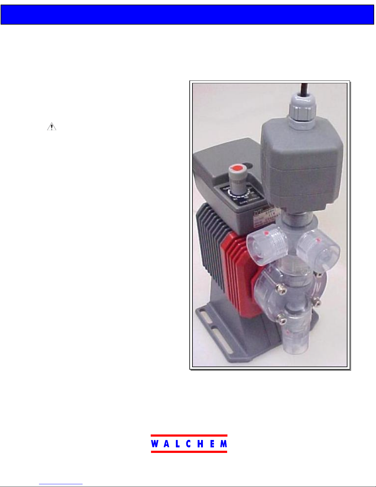
PRODUCT DESCRIPTION
PPPPOSI
The
metering pump is truly moving liquid into the
system and has not lost prime. Utilizing
proprietary circuitry coupled with advanced
pressure sensing technology, the
Sensor provides the most accurate and non-
intrusive flow verification device to date.
Without any moving parts in the sensor, the
standard flow path of the pump is preserved
and the liquid does not move through any gears
or lift a magnet to actuate a pulse in the sensor.
This eliminates any concern of plugging,
leaking or jamming of the flow path or sensing
mechanism.
OSIFLOW
OSIOSI
Sensor will verify that your
PPPPOSI
OSIFLOW
OSIOSI
The output signal of the
an open-collector contact closure
corresponding with each flow pulse.
Additionally, a visual green LED is mounted
on the topside of the sensor. This is always
ON to indicate power and will briefly flash
OFF in sync with each output signal.
PPPPOSI
The
pressure. If the pump becomes either air-locked or in a dead head condition, the sensor will no longer
output a signal. And unlike the competition, if the discharge line breaks or becomes disconnected,
pressure will be lost and the
OSIFLOW will send out a signal with every stroke as long as there is liquid pumping against
OSIOSI
Five Boynton Road Hopping Brook Park Holliston, MA 01746 USA TEL 508-429-1110 FAX 508-429-7433
PPPPOSI
OSIFLOW Sensor is
OSIOSI
PPPPOSI
OSIFLOW sensor will stop signaling flow.
OSIOSI
Member of the Walchem Group
Page 2
W
A L C H E
SAFETY & CAUTION NOTES
Wear Protection
When working on or around a metering pump,
always wear proper protective clothing and
equipment as recommended by the supplier of the
chemical being pumped.
Remove Power
Disconnect the pump and sensor from their electrical
power sources before performing any maintenance.
If the pump starts operation during maintenance,
chemical may be sprayed & cause injury.
Application of Product
Use the PosiFlow within the specified range.
Using the PosiFlow in any other application than its
intended purpose may result in personal injury or
damage to the product.
Not observing precautions may cause injury or damage to the product.
SPECIFICATIONS
1. Identification:
Part Number Description Material
FCP-1VC PosiFlow Sensor, VC VC
FCP-1VE PosiFlow Sensor, VE VE
FCP-1PC PosiFlow Sensor, PC PC
FCP-1PE PosiFlow Sensor, PE PE
2. Applicable Models and Ordering Information:
PPPPOSI
OSIFLOW Sensor is available for the 10, 15 & 20 sizes of EH and EZ
The
OSIOSI
pumps with matching liquid end codes. It will mount into either the manual air
vent valve or the Multi
auto air vent valve (VCA or VCC codes).
3. Electrical
Power Source Voltage 12VDC +
Current 25mA max (@12VDC)
Output Type Non-Isol. Open Collector (NPN)
Rating 24VDC max (from source)
Wave Form 100mS +
Indicator LED (Green)
Cable
Length 9.75 Feet
Cross Section 3.1x10
Termination #6 Fork Terminal
4. Materials of Construction
Housing PVC or GFRPP
O-Rings FKM or EPDM
Sensor 96% Ceramic (Al2O3)
MultiFunction valve, but at this time it is not compatible with
MultiMulti
2VDC
15mS
-4 in2
Power Source
Use only stable DC voltage within the specified range.
Voltage outside the range may cause damage or fire.
Do Not Modify the Product
Never attempt to modify the PosiFlow. Alteration of
the product may produce a dangerous situation and
will void the warranty.
Location
Do not use the PosiFlow Sensor in an aggressive
environment. Exposure to liquid or excess humidity
may cause failure or electrical shock.
Do Not Use a Damaged Sensor
Using a damaged PosiFlow may cause chemical
leakage or electrical shock.
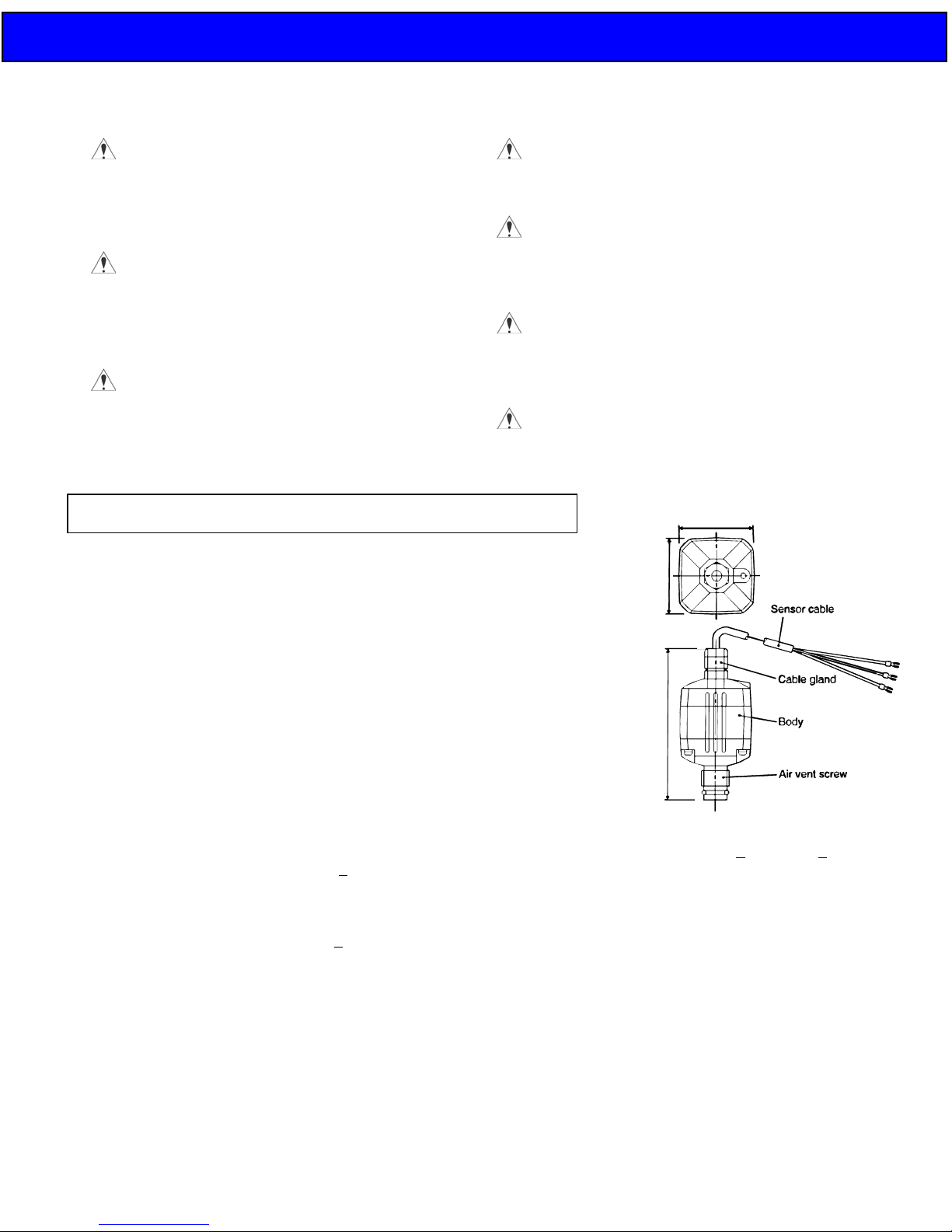
1.89”
3.82”
5. Output Pressure Range*: 30+
6. Environment:
Ambient Temperature 0-120°F
Ambient Humidity 35-90% RH
Storage Temperature 32-120°F
Liquid Temperature 32-105°F (PVC models)
32-140°F (GFRPP models)
PPPPOSI
*The
OSIFLOW Sensor requires a minimum of 30PSI
OSIOSI
total back pressure. If this is not available, the injection
valve supplied with the pump can be retrofitted with an
optional high-pressure spring, part number E90375.
This spring will increase the back pressure at the pump
approximately 50PSI.
M
1.89”
5PSI to 150+15PSI
Page 3

W
A L C H E
t
INSTALLATION
Disconnect the pump from the electrical power source before performing maintenance.
Release the pressure in the discharge tubing before disconnecting or performing any maintenance on the pump.
Plumbing
1. Unscrew and remove the air vent knob from the manual air vent valve (or Multi
clockwise.
2. Insert the PosiFlow Sensor directly where the air vent knob was located (turn clockwise to secure).
CAUTION: The wires on the sensor will want to twist as it is being screwed into the
valve. While installing the sensor, also turn the cable to avoid wire twisting and
damage. If this is not possible, pre-twist the wire in the opposite direction about 5
turns to relieve stress during sensor installation.
3. The function of the manual air vent is not lost when using the PosiFlow Sensor.
Simply use the sensor itself as the manual air vent valve when necessary, turning it
one-half to one turn counter clockwise to bleed out air, prime the pump or release the
discharge pressure.
Installing the PosiFlow Sensor into the manual air vent valve.
Electrical
Wiring
The PosiFlow Sensor requires 12VDC power to operate. Attach the RED wire to +12VC and the BLACK wire to GND
(common). The output signal is a closed contact between the WHITE and BLACK wires.
CAUTION: Do not run the PosiFlow cable near other power lines carrying high current or high power equipment as line
noise can cause sensor damage or abnormal operation.
Output Signal
The output signal (white wire) is normally high and drops to zero when the PosiFlow senses a pulse from the discharge of
the pump. The time of the closed contact is 100mS. See the output wave form below.
This type of signal acts similar to a contact closure from a reed switch device between the signal (white) and the common
(black) wires. The only difference is that the receiving device will see a trigger on the rise of the output instead of the fall
(reverse of typical).
MultiFunction Valve) by turning counter-
MultiMulti
Installing the PosiFlow
Sensor into the
Multi
MultiFunction Valve
MultiMulti
M
PosiFlow Outpu
Page 4

W
A L C H E
OPERATION
Back Pressure Requirement
In order for the PosiFlow Sensor to function, a minimum of 30PSI system pressure is required at the sensor. In cases
where there is little or no system pressure, the standard injection check valve supplied with each pump can be modified
with a high-pressure spring that adds approximately 50PSI. Contact your local distributor to order Part Number E90375.
Operation
Turn on the pump. The PosiFlow will not output a signal until the pump actually is moving liquid. For priming of the
pump, the PosiFlow sensor may have to be turned one-half or one full turn counter-clockwise to vent the air out the vent
connection.
CAUTION: Tubing should always be connected from the air vent back into the supply tank or suitable drain. Do not
submerge the air return tubing below the chemical surface level in the supply tank.
Once fully primed, close the air vent by tightening down the PosiFlow Sensor. The green LED on the PosiFlow should
now begin to flash OFF with each pump stroke and it will output a pulse simultaneously. The PosiFlow will continue to
output pulses as long as it senses pressure changes. If the pump loses prime or is air locked, the compression of air with
each pump stroke will not generate enough pressure for the PosiFlow to sense and it will not output pulses. Similarly,
excessive pressures will cause the pump to begin to stall and not generate enough pressure differential for the PosiFlow
to sense.
NOTE: If there is any trapped air, long lengths of flexible tubing, or any area of relief or expansion during a
deadhead situation, the PosiFlow may still keep sensing flow. This is more likely in C15/20 sized pumps.
Output Signal
The output signal from the PosiFlow simulates a contact closure. It can be used in any device that takes a non-powered
contact closure as a switch. It can also be used to drive another EH series pump.
The Walchem Web
The Web
WebMaster will alarm a no flow condition after a customer-set time limit and will also totalize pumped volume
WebWeb
once the pump is calibrated.
In a similar manner, a PLC or other device can be programmed to interpret the PosiFlow signal in any number of ways.
TROUBLESHOOTING & MAINTENANCE
CAUTION: Do NOT disassemble the PosiFlow Sensor! There are no user serviceable parts inside and the components
No output pulses from the
PosiFlow Sensor
(Output pulse is not synchronous
with the pump stroke)
Liquid Leakage from around the
PosiFlow Sensor
WebMaster is designed to accept the PosiFlow Sensor signal. It both powers and reads the signal.
WebWeb
can easily be damaged. Disassembly of the Sensor will void the manufacturer’s warranty.
Problem Possible Cause Corrective Action
o Incorrect or disconnected wiring
o Pump has lost prime (air-lock)
o Pump is drawing in air
o Disconnected or cut tubing
o Pinched or clogged tubing
o Foreign material lodged in pump
o PosiFlow Sensor not tightened
down (in the air vent condition)
o Not enough back pressure
o O-ring seals on PosiFlow missing,
dislocated, or worn
o Double check wire connections
o Unscrew PosiFlow one-half turn to
vent air
o Check the tubing and fitting
connections
o Correct/Replace the tubing
o Correct/Replace Tubing
o Disassemble/inspect/clean pump
head assembly
o Tighten the PosiFlow Sensor by
turning clockwise by hand.
o Check Injection Valve location and
system pressure. Install the High
Pressure Spring (E90375) if there
is little or no system pressure
o Re-install or replace the o-rings
M
Five Boynton Road Hopping Brook Park Holliston, MA 01746 USA TEL 508-429-1110 FAX 508-429-7433
E00098 PosiFlow Sensor
Instruction Manual
REVISION A 4/10/02
Member of the Walchem Group
 Loading...