

Page 1
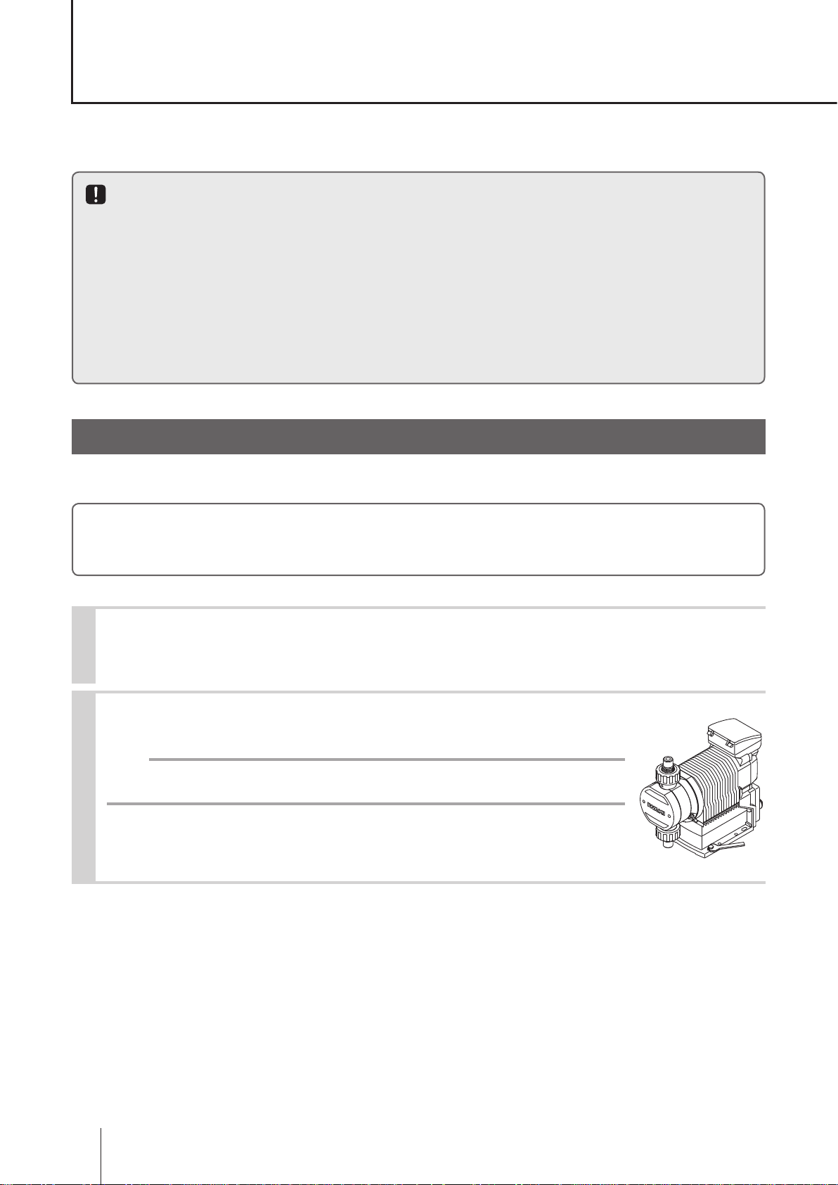
IX-C series (North America)
Safety instructions
Overview Installation Operation Maintenance Specication
Instruction manual
Thank you for choosing our product.
Please read through this instruction manual before use.
This instruction manual describes important precautions and instructions for the product. Always keep it on hand for quick reference.
©2015 IWAKI CO., LTD.
Page 2
Order conrmation
Open the package and check that the product conforms to your order. If any problem or
inconsistency is found, immediately contact your distributor.
a. Check if the delivery is correct.
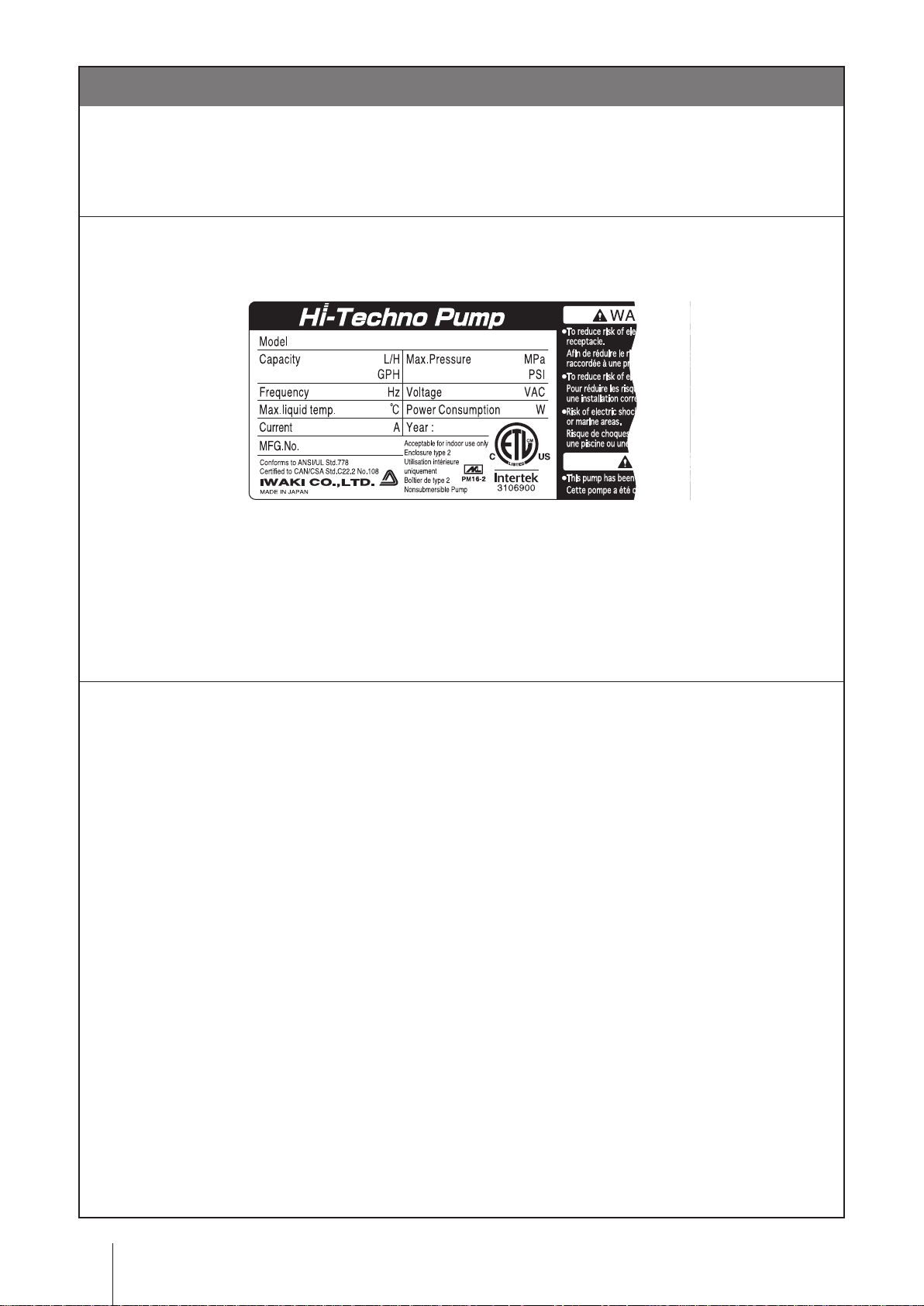
Check the nameplate to see if the information such as model codes, discharge capacity and discharge
pressure are as ordered.
b. Check if the delivery is damaged or deformed.
Check for transit damage and loose bolts.
Order conrmation
2
Page 3

Contents
Order conrmation ..........................................................................................................................................2
Safety instructions .................................................................... 6
Warning ..........................................................................................................................................................7
Caution ...........................................................................................................................................................8
Precautions for use ....................................................................................................................................10
Overview ...................................................................................12
Introduction .................................................................................................................................................12
Pump structure & Operating principle ......................................................................................................12
Features ...................................................................................................................................................13
Operational function ...................................................................................................................................13
Manual mode ...........................................................................................................................................13
EXT mode ................................................................................................................................................14
Analogue proportional control .............................................................................................................14
Pulse control .......................................................................................................................................16
Batch control .......................................................................................................................................16
Interval batch control ...........................................................................................................................18
AUX function ............................................................................................................................................18
Priming function .......................................................................................................................................18
STOP functions ........................................................................................................................................19
STOP function .....................................................................................................................................19
Pre-STOP function ..............................................................................................................................19
Analogue output function .........................................................................................................................19
Protective functions ..................................................................................................................................20
Interlock function .................................................................................................................................20
Diaphragm rupture detection ..............................................................................................................20
Pressure overload/Failed rotation control detection ...........................................................................20
Alarm output function ..........................................................................................................................21
Other functions .........................................................................................................................................21
Suction speed setting ..........................................................................................................................21
Maximum ow rate setting ..................................................................................................................21
Diaphragm position adjustment ..........................................................................................................21
Anti chattering programming ...............................................................................................................21
Output logic setting .............................................................................................................................21
Flow unit setting ..................................................................................................................................21
Language setting ................................................................................................................................21
Keypad lock .........................................................................................................................................21
Default setting .....................................................................................................................................21
Part names ...................................................................................................................................................22
Pump ........................................................................................................................................................22
Contents
3
Page 4

Operational panel .....................................................................................................................................23
Basic displays & Pump states .............................................................................................................24
Identication codes ....................................................................................................................................25
Pump ........................................................................................................................................................25
Installation .............................................................................. 26
Pump mounting ...........................................................................................................................................26
Pipework ......................................................................................................................................................27
Piping layout ........................................................................................................................................27
Drain port (Vent hole) .................................................................................................................................28
Wiring ...........................................................................................................................................................29
End terminals ...........................................................................................................................................29
Power voltage/Earthing ............................................................................................................................30
Signal wire connection .............................................................................................................................31
EXT IN ................................................................................................................................................32
STOP IN ..............................................................................................................................................32
AUX IN/Analog OUT ...........................................................................................................................33
Alarm OUT (DIN connector) ................................................................................................................33
Operation ................................................................................. 34
Before operation .........................................................................................................................................34
Points to be checked ................................................................................................................................34
Retightening of pump head xing bolts ....................................................................................................34
Commissioning .........................................................................................................................................35
Before a long period of stoppage (One month or more) ..........................................................................35
Perform a calibration ..................................................................................................................................36
Calibration process ..................................................................................................................................37
Operation programming .............................................................................................................................39
Programming ow ....................................................................................................................................40
Menu screen ............................................................................................................................................41
EXT mode selection ............................................................................................................................42
Calibration ...........................................................................................................................................44
Signal input setting ..............................................................................................................................45
Analogue output setting ......................................................................................................................46
Alarm output setting (OUT 1) <Mechanical relay> ..............................................................................47
Alarm output setting (OUT 2) <PhotoMOS relay> ..............................................................................49
Data logging ........................................................................................................................................50
Programming of other functions ..........................................................................................................51
Operation .....................................................................................................................................................54
Manual operation .....................................................................................................................................54
EXT operation ..........................................................................................................................................54
AUX function ............................................................................................................................................55
Priming function .......................................................................................................................................55
Keypad lock ..............................................................................................................................................56
4
Contents
Page 5

Keypad lock activation ........................................................................................................................56
Keypad lock release ............................................................................................................................56
Emergency stop ..................................................................................................................................56
Maintenance .............................................................................57
Troubleshooting ..........................................................................................................................................58
Pump ...................................................................................................................................................58
Error messages ...........................................................................................................................................59
Inspection ....................................................................................................................................................59
Daily inspection ........................................................................................................................................59
Periodic inspection ...................................................................................................................................59
Wear part replacement ...............................................................................................................................60
Wear part list ............................................................................................................................................60
Before replacement ..................................................................................................................................62
Valve set replacement ..............................................................................................................................62
Diaphragm replacement ...........................................................................................................................63
Exploded view .............................................................................................................................................67
Pump head, Drive unit & Control unit .......................................................................................................67
Pump head ...............................................................................................................................................68
IX-C150 TC N ......................................................................................................................................68
IX-C150 TC FA ....................................................................................................................................69
IX-C150 S6 N ......................................................................................................................................70
IX-C150 S6 FA ....................................................................................................................................71
IX-C060 TC N .....................................................................................................................................72
IX-C060 TC FA ....................................................................................................................................73
IX-C060 S6 N ......................................................................................................................................74
IX-C060 S6 FA ....................................................................................................................................75
Specications/Outer dimensions ..............................................................................................................76
Specications ...........................................................................................................................................76
Pump ...................................................................................................................................................76
Power cable ........................................................................................................................................76
Body colour .........................................................................................................................................76
Control unit ..........................................................................................................................................77
Outer dimensions .....................................................................................................................................78
IX-C060/-C150 TC/TE N-TB ...............................................................................................................78
IX-C060/-C150 TC/TE FA-TB .............................................................................................................79
IX-C060/-C150 TC/TE N-RF ...............................................................................................................80
IX-C060/-C150 TC/TE FA-RF .............................................................................................................81
IX-C060/-C150 S6 N-TB .....................................................................................................................82
IX-C060/-C150 S6 FA-TB ...................................................................................................................83
IX-C060/-C150 S6 N-RF .....................................................................................................................84
IX-C060/-C150 S6 FA-RF ...................................................................................................................85
Contents
5
Page 6
Safety instructions
Read through this section before use. This section describes important
information for you to prevent personal injury or property damage.
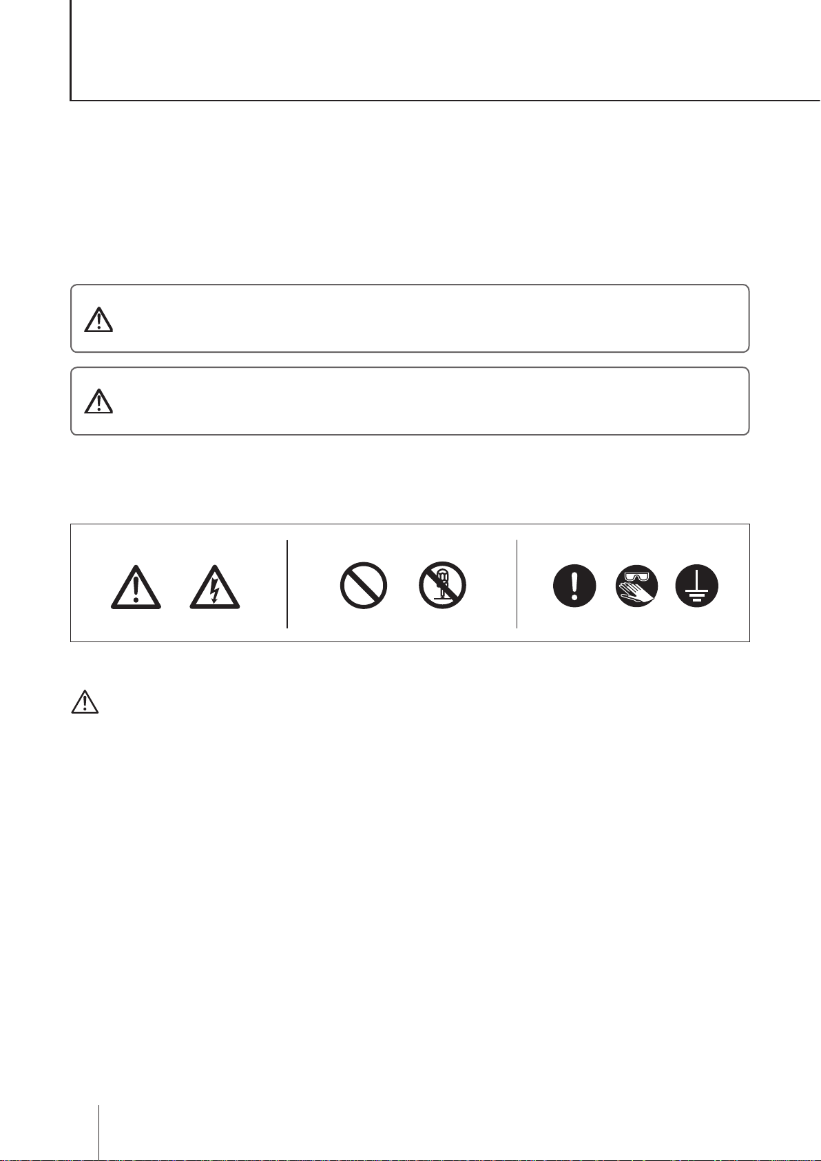
■ Symbols
In this instruction manual, the degree of risk caused by incorrect use is noted with the follow-
ing symbols. Please pay attention to the information associated with the symbols.
Indicates mishandling could lead to a fatal or serious injury
WARNING
CAUTION
A symbol accompanies each precaution, suggesting the use of "Caution", "Prohibited actions"
and specic "Requirement".
accident.
Indicates mishandling could lead to personal injury or prop-
erty damage.
Caution marks Prohibition mark Requirement mark
Caution
Electrical
shock
Prohibition
Do not remodel
Requirement
Wear
protectors
Earthing
Export Restrictions
Technical information contained in this instruction manual might be treated as controlled tech-
nology in your countries, due to agreements in international regime for export control.
Please be reminded that export license/permission could be required when this manual is
provided, due to export control regulations of your country.
Safety instructions
6
Page 7
Electrical
shock
Requirement
Safety instructions
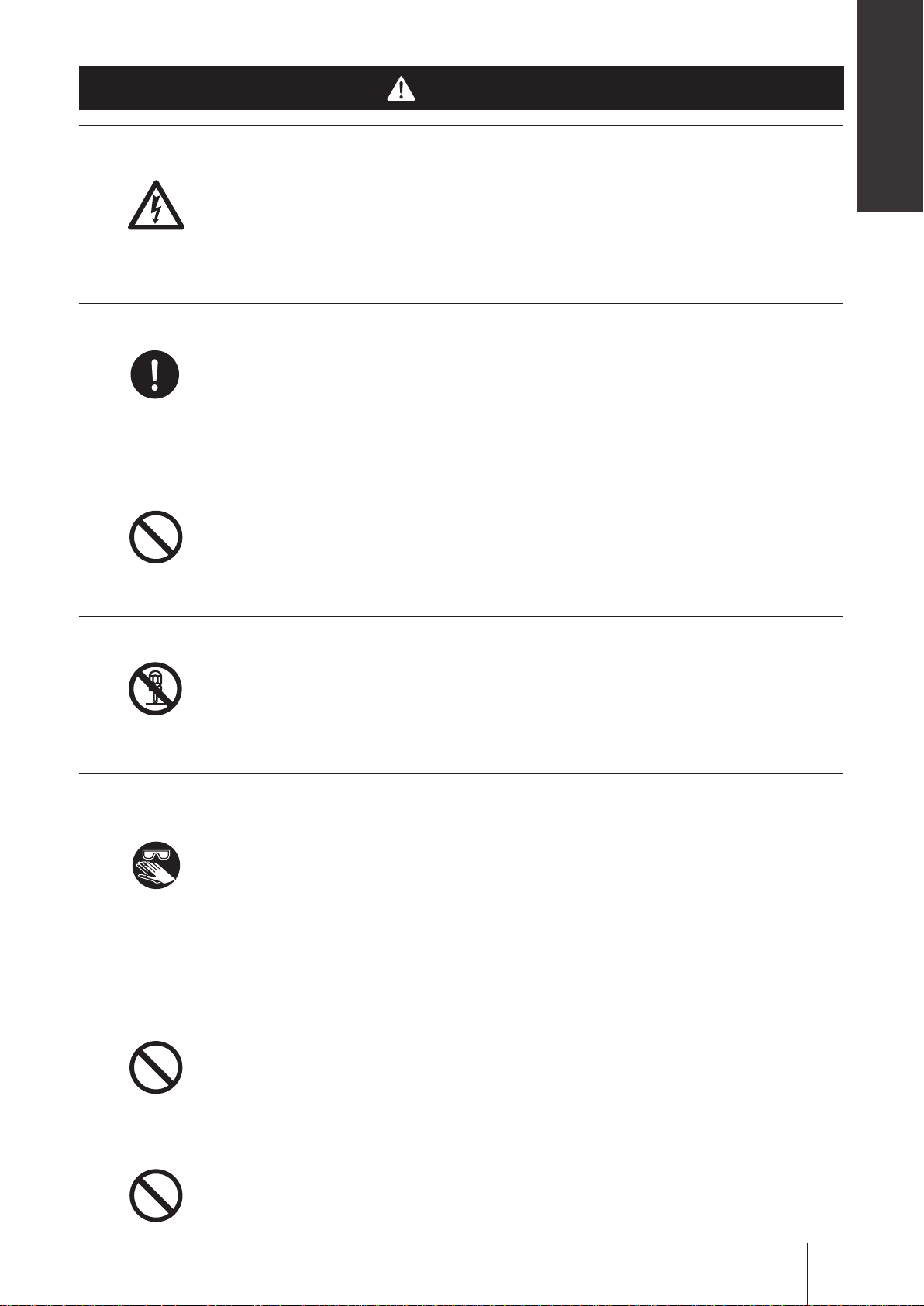
WARNING
Turn off power before service
Risk of electrical shock. Be sure to turn off power to stop the pump and
related devices before service is performed.
Couper l’alimentation électrique de la pompe avant intervention
Intervenir sur la pompe sans avoir au préalablement coupé l’alimentation
électrique peut déclencher des décharges électriques. Avant d’entreprendre
n’importe quel type d’intervention, veillez à mettre la pompe et tout dispositif
connexe hors tension à l’aide de l’interrupteur prévu à cet effet.
Stop operation
If you notice any abnormal or dangerous conditions, suspend operation
immediately and inspect/solve problems.
Arrêter le fonctionnement
Si vous détectez une anomalie ou des signes suspects et inhabituels
pendant le fonctionnement, interrompez immédiatement les opérations et
inspectez, résolvez les problèmes.
Prohibition
Do not remodel
Wear
protectors
Do not use the pump in any condition other than its intended purpose
The use of the pump in any conditions other than those clearly specied
may result in failure or injury. Use this product in specied conditions only.
Se conformer uniquement aux applications prévues
La pompe doit être utilisée conformément à l’usage pour lequel elle a été
prévue et dans le respect de ses caractéristiques techniques. Toute utilisa-
tion non conforme peut entraîner un incident ou endommager le dispositif.
Do not modify the pump
Alterations to the pump carries a high degree of risk. It is not the manufacturer's
responsibility for any failure or injury resulting from alterations to the pump.
Ne pas modier la pompe
Ne jamais modier une pompe sous peine de causer un incident grave.
Iwaki ne pourra en aucun cas être tenu responsable d’un incident ou de
dégâts survenus à la suite d’une modication du dispositif.
Wear protective clothing
Always wear protective clothing such as an eye protection, chemical re-
sistant gloves, a mask and a face shield during disassembly, assembly or
maintenance work. The specic solution will dictate the degree of protec-
tion. Refer to MSDS precautions from the solution supplier.
Porter un équipement de protection
Toujours porter un équipement de protection (lunettes, gants ré-
sistants aux produits chimiques, masque, casque) durant le démontage,
l’assemblage et la maintenance.
Le travail effectué dictera le degré de protection. Référez-vous au MSDS
de la solution proposée par le fournisseur.
Prohibition
Prohibition
Do not damage the power cable
Do not pull, knot, or crush the power cable. Damage to the power cable
could lead to a re or electrical shock if cut or broken.
Ne pas endommager le câble électrique
Ne pas tirer ou faire un nœud avec le câble électrique. Endommager un
câble électrique pout provoquer une incendie ou une décharge électrique.
Do not operate the pump in a ammable atmosphere
Do not place explosive or ammable material near the pump.
Ne pas utiliser la pompe dans une atmosphère explosive
Pour votre sécurité, du matériel dangereux ou inammable ne doit pas
être placé près de la pompe.
WARNING
7
Page 8
Risk of electric shock
This pump is supplied with a grounding conductor and grounding-type
attachment plug. To reduce the risk of electric shock, be certain that it is
connected only to a properly grounded, grounding type receptacle.
Electrical
shock
Requirement
Prohibition
Risque de choc électrique
La pompe est fournie avec un conducteur pour mise à la terre et une prise
courant. An de réduire le risque de choc électrique, veillez à ce que la
terre soit correctement raccordée.
CAUTION
Qualied personnel only
The pump should be handled or operated by qualied personnel with a
full understanding of the pump. Any person not familiar with the product
should not take part in the operation or maintenance of the pump.
Opérateur qualié uniquement
La pompe doit être manipulée ou utilisée par du personnel qualié con-
naissant parfaitement la pompe. Tout autre personne étrangère ne doit
pas prendre part à l’utilisation ou à la maintenance de la pompe.
Use specied power only
Do not apply power other than that specied on the nameplate. Otherwise,
failure or re may result. Ensure the pump is properly grounded.
Utilisez une tension appropriée uniquement
Ne pas appliquer une autre tension que celle spéciée sur la plaque sig-
nalétique sinon, il peut en résulter une panne ou une incendie. Assurezvous également de la mise à la terre de la pompe.
Prohibition
Caution
Prohibition
Keep electric parts and wiring dry
Risk of re or electric shock. Install the pump where it can be kept dry.
Ne mouillez pas les parties électriques ou les câbles
Risque d’incendie ou de décharge électrique. Installez la pompe dans un
endroit sec.
Ventilation
Fumes or vapors can be hazardous with certain solutions. Ensure proper
ventilation at the operation site.
Ventilation
Manipuler un produit toxique ou odorant peut provoquer une intoxication.
Prévoyez une ventilation sufsante à l’endroit de la manipulation.
Do not install or store the pump:
• In a ammable atmosphere.
• In a dusty/humid environment.
• Where ambient temperature can exceed 0-50ºC (32-122°F).
• In direct sunlight or wind & rain.
N’installez ou ne stockez pas la pompe dans les endroits suivantes:
• Dans une atmosphère inammable
• Dans un endroit poussiéreux ou humide.
• Dans une place où la température n’est pas comprise entre 0 et 50 °C.
• Directement sous le soleil, le vent ou la pluie.
8
This pump has been evaluated for use with water only.
Cette pompe a été testée uniquement avec de l'eau.
Caution
CAUTION
Page 9
Spill precautions
Ensure protection and containment of solution in the event of plumbing or
pump damage (secondary containment).
Safety instructions
Requirement
Prohibition
Earthing
Electrical
shock
Déversement accidentel
Prenez des mesures protectrices contre tout incident résultant d’un débit
trop important de la pompe ou d’une casse de tuyauterie.
Do not use the pump in a wet location
The pump is not waterproof. Use of the pump in wet or extremely humid
locations could lead to electric shock or short circuit.
N’utilisez pas la pompe sous l’eau
La pompe n’est pas complètement étanche. Utiliser la pompe dans l’eau
ou dans un endroit très humide peut créer une décharge électrique ou un
court-circuit.
Grounding
Risk of electrical shock! Always properly ground the pump. Conform to lo-
cal electric codes.
Mise à la terre
Veillez à ne pas faire fonctionner la pompe sans avoir au préalable prévu
une mise à la terre. Celle-ci permettra d’éviter d’éventuelles décharges
électriques. Vériez que le câble de mise à la terre est bien branché.
Install a GFCI (earth leakage breaker)
An electrical failure of the pump may adversely affect other devices on the
same line. Purchase and install a GFCI (earth leakage breaker) separately.
Détecteur de fuites à la terre
Un problème électrique peut affecter défavorablement le dispositif. Achet-
ez et installez un détecteur de fuites à la terre.
Requirement
Prohibition
Requirement
Preventative maintenance
Follow instructions in this manual for replacement of wear parts. Do not
disassemble the pump beyond the extent of the instructions.
Remplacement des pièces usées
Suivez les instructions de ce manuel pour remplacer les pièces usées. Ne
démontez pas la pompe au-delà des instructions.
Do not use a damaged pump
Use of a damaged pump could lead to an electric shock or death.
N’utilisez pas une pompe endommagée
Utiliser une pompe endommagée peut provoquer une décharge électrique
ou la mort.
Disposal of a used pump
Dispose of any used or damaged pump in accordance with local rules and
regulations. If necessary, consult a licensed industrial waste disposal company.
Elimination des pompes usées
Elle doit se faire en conformité avec les règles locales en vigueur (consult-
ez une entreprise certiée et spécialisée).
Check pump head bolts
Liquid may leak if any of the M8/M5 pump head bolts become loose. Remove
the bolt cover and tighten the bolts diagonally and evenly by 12N•m (IX-C150)
or 3.5N•m (IX-C060) before initial operation and at regular intervals.
Caution
Serrez la tête de pompe
Il pourrait y avoir une fuite de liquide si les 8 boulons M8/M5 du corps de
pompe ne sont pas bien serrés. Enlevez le cache boulon et resserrez les
boulons diagonalement et uniformément (12N•m: IX-C150, 3.5N•m: IXC060) avant la première utilisation et à intervalles réguliers.
CAUTION
9
Page 10

Precautions for use
• Electrical work should be performed by a qualified electrician. Otherwise,
personal injury or property damage could result.
Le raccordement électrique de la pompe doit être effectué par du person-
nel qualié sinon, il pourrait y avoir un dommage corporel ou incorporel.
• Do not install the pump:
–In a ammable atmosphere.
–In a dusty/humid place.
–In direct sunlight or wind & rain.
–Where ambient temperature can exceed 0-50ºC (32-122°F).
Ne pas installer la pompe dans les endroits suivants:
–Dans une atmosphère inammable
–Dans une atmosphère poussiéreuse ou humide.
–Sous les rayonnements du soleil, dans le vent ou sous la pluie.
–La température ambiante doit être comprise entre 0 et 50°C.
• Select a level location, free from vibration, that won't hold liquid. Anchor
the pump with four M8 bolts so it doesn't vibrate. If the pump is not in-
stalled level, output may be affected.
Choisissez un endroit où il n’y a pas de vibrations et où le liquide peut
s’évacuer. Fixez la pompe à l’aide de visses M8 de façon à ne pas avoir de
vibrations. Si la pompe est inclinée, le débit peut être réduit.
• When two or more pumps are installed together, vibration may be signifi-
cant, resulting in poor performance or failure. Select a solid foundation
(concrete) and fasten anchor bolts securely to prevent vibration during
operation.
Caution
Si plusieurs pompes sont installées ensemble, elles interagissent et les
vibrations peuvent devenir importantes, ce qui engendre des performances
médiocres ou des ratures. Choisissez un endroit solide et xez les boulons
correctement pour évitez les vibrations pendant le fonctionnement.
• Allow sufficient space around the pump for easy access and maintenance.
Prévoyez de l’espace autour de la pompe pour faciliter l'accès et la mainte-
nance.
• Install the pump as close to the supply tank as possible.
Installez la pompe le plus près possible du tank de produit.
• When handling liquids that generate gas bubbles (sodium hypochlorite or
hydrazine solution), install the pump in a cool and dark place. Flooded suc-
tion installation is strongly recommended.
Installez la pompe dans une place froide à l’abri du soleil lorsqu’il s’agit
du dosage de produits dégazant tels que l’hypochlorite de sodium ou
l’hydrazine. Mettre la pompe en charge est vivement recommandé.
• The suction line I.D. should be equal to or wider than the I.D. of the pump.
La ligne d’aspiration doit être plus large que l’entrée de la pompe.
• Build up a flooded suction system for the viscous liquid delivery of
300mPa•S or more.
Caution
Caution
Caution
Caution
Caution
Pour les liquides ayant une viscosité supérieure ou égale à 300 mPa.s il
faut mettre la pompe en charge.
Precautions for use
10
Caution
Page 11
• Use measures to keep the pump connections free from stress. Weight and
thermal expansion/contraction of the piping can stress connection points.
Safety instructions
La pompe ne doit pas être soumise à des effets éventuels de dilation ou de
contraction du pipe dus à un stress thermique.
• Overload protection will stop pump operation when discharge pressures
reach 1.3 to 2 times higher than the pump maximum. If the discharge line
cannot conservatively handle the maximum pressure, use a relief valve to
safely depressurize the discharge line.
Un dispositif de protection en cas de surcharge doit pouvoir arrêter le dos-
age quand la pression au refoulement s’élève de 1,3 à 2 fois le maximum
admis. Installez une vanne de sécurité pour relâcher la pression de la ligne
de refoulement si la ligne de refoulement ne peut pas supporter de haute
pression.
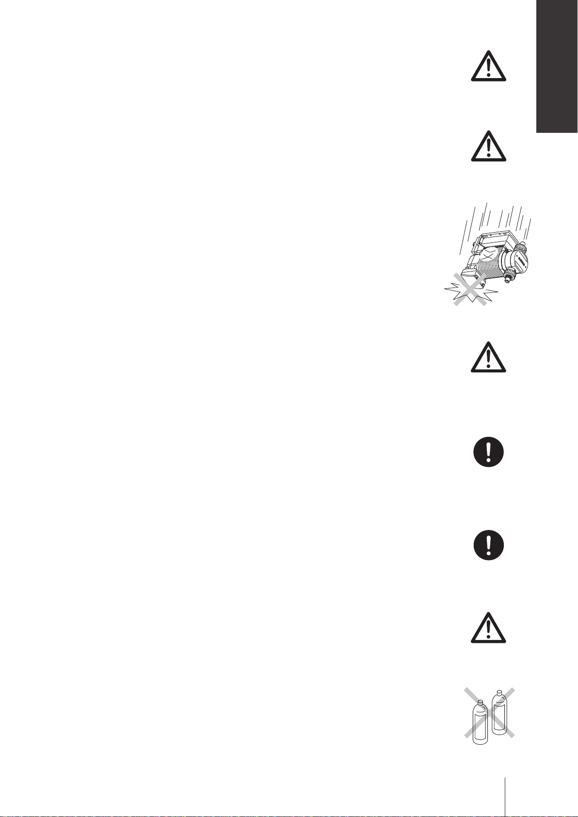
• Use care handling the pump. Do not drop. An impact may affect pump
performance. Do not use a pump that has been damaged to avoid the risk
of electrical damage or shock.
Veillez à ne pas laisser tomber la pompe sur le sol. Un impact important
pourrait réduire les performances de la pompe. Ne pas utiliser une pompe
endommagée sinon il pourrait y avoir un courant de fuite ou une décharge
électrique.
• The pump has a rating of IP65 equivalent, but is not waterproof. Do not op-
erate the pump while wet with solution or water. Failure or injury may result.
Immediately dry off the pump if it gets wet.
Caution
Caution
La pompe est IP65 équivalent mais n’est pas complètement étanche. Ne
pas laisser la pompe couverte de liquide pompé ou sous la pluie. Il pour-
rait y avoir des ratés ou préjudices. Si la pompe a été mouillée, sechez-la
directement.
• Do not close discharge line during operation. Solution may leak or pump
and piping may break. Install a relief valve to ensure safety and prevent
damaged plumbing.
Ne fermez pas la ligne de refoulement lorsque la pompe est en fonc-
tionnement sinon il pourrait y avoir des fuites de liquide ou la pompe et la
tuyauterie pourraient céder. Installez une soupape de sécurité pour des
raisons de sécurité et pour éviter tout dommage de la tuyauterie.
• Solution in the discharge line may be under pressure. Release the pres-
sure from the discharge line before disconnecting plumbing or disassembly
of the pump to avoid solution spray.
Le liquide au refoulement peut être sous pression. Relâchez la pression
du refoulement avant de démonter la pompe ou d’enlevez le tubage pour
éviter tout jet de liquide.
• Wear protective clothing when handling or working with pumps. Consult
solution MSDS for appropriate precautions. Do not come into contact with
residual solution.
Portez un équipement de sécurité lorsque vous manipulez la pompe. Consultez le MSDS pour utilisez les précautions appropriées. Evitez tout con-
tact avec le liquide chimique.
Caution
Requirement
Requirement
Caution
• Do not clean the pump or nameplate with a solvent such as benzine or
thinner. This may discolour the pump or erase printing. Use a dry or damp
cloth or a neutral detergent.
Ne nettoyez pas la pompe ou la plaque signalétique à l’aide d’un solvant
comme le benzène ou le white spirit. Cela pourrait décolorer la pompe ou
effacer l’impression. Utilisez un tissu sec ou mouillé avec de l’eau ou un
détergent neutre.
Benzine
Precautions for use
Thinner
11
Page 12
Overview
Pump characteristics, features and part names are described in this
section.
Introduction
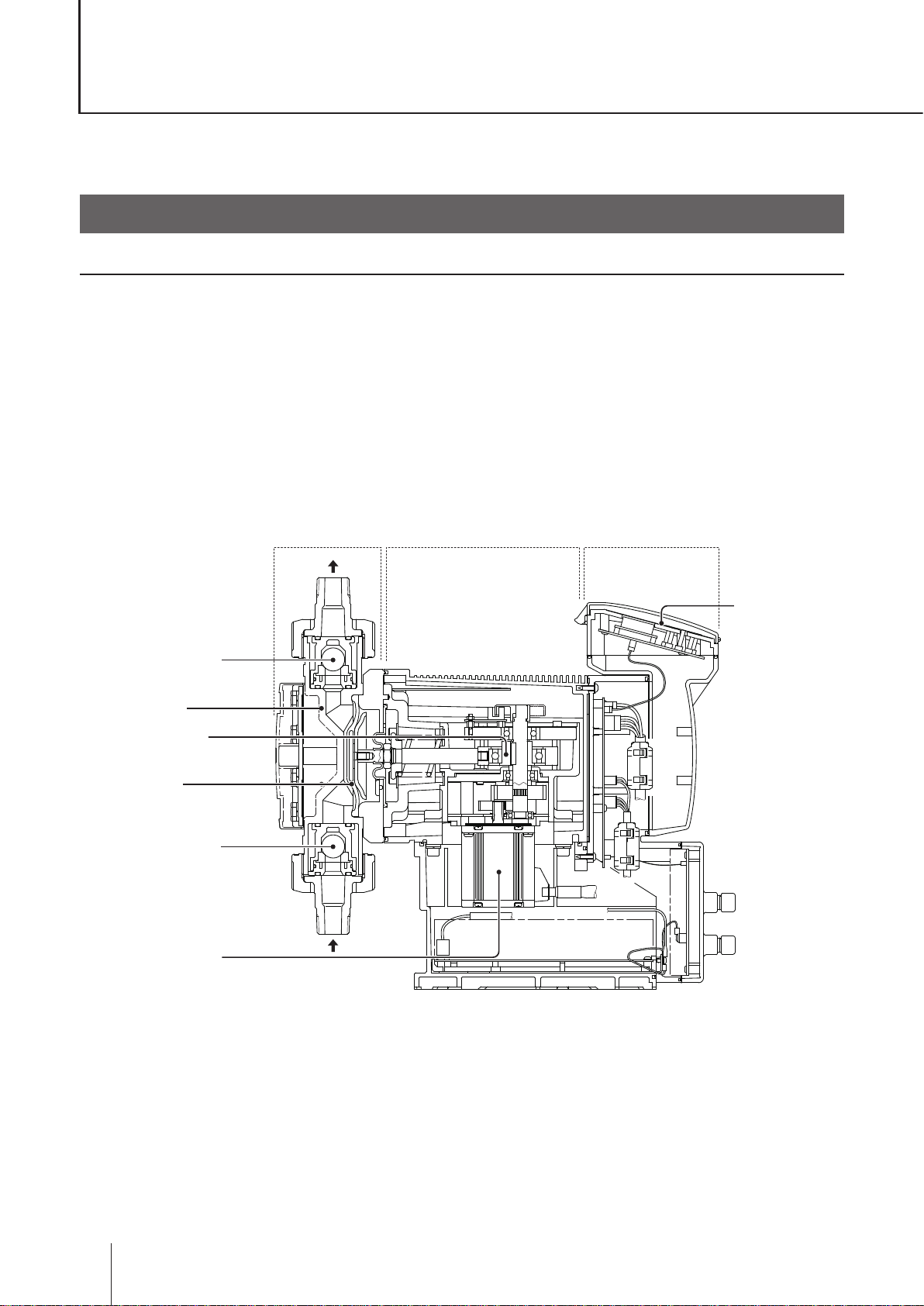
Pump structure & Operating principle
The IX series are diaphragm pumps with a brushless DC (BLDC) motor and feature a high turndown ratio &
automatic controls.
Principle of operation
In the IX series design, a BLDC motor rotation controls the ow rate.
Motor rotation is transmitted to an eccentric cam through a reduction gear and then converted to reciprocating
motion. Volumetric change occurs in the pump chamber as the diaphragm moves back and forth and liquid is
pumped because of the suction and discharge check valves. Discharge speed changes the ow rate while the
suction speed remains the same at any ow rate.
Control unitPump head Drive unit
Pump head valve
(discharge side)
Pump head
Eccentric cam
Diaphragm
Pump head valve
(suction side)
Brushless motor
OUT
Keypads
IN
12
Introduction
Page 13
Features
● High turndown ratio
Use of a BLDC control motor enables accurate control with a wide turndown ratio.
● High repeatability
Highly-efcient valve design and accurate discharge-/suction-speed controls assure the high repeatability of
chemical dosing (±1%).
● Energy-saving design
Use of helical gears and an assist spring reduces power consumption by 70% compared to our existing me-
tering pump designs (spring back).
● Automatic control
The IX can automatically run along with analogue-, pulse-, batch- or interval batch-operation programming.
● Multivoltage operation
The IX series can be used in all countries thanks to the universal power voltage (100-240VAC).
● Safety design
A diaphragm rupture detection ensures user safety and a pressure overload detection protects the pump and
pipework from an accidental discharge line pressure rise.
● Ingress protection rating of IP65
Overview
Operational functions
Manual mode
Run/stop the pump by key operation. The ow rate can be changed by the up and the down keys at any time
during operation or stop. The operation LED lights in green colour during operation. See page 54 for detail.
Key operation
(Push key)
Run
Pump operation
Stop
Run
Stop
Operational functions
13
Page 14
EXT mode
■ Analogue proportional control
ANA. P (analogue preset) programming (see page 42 & 54)
Select a proportional control pattern. 4 - 20mA, 20 - 4mA, 0 - 20mA and 20 - 0mA are available. During opera-
tion, the display shows the current ow rate. To show the current value, push the key. To return to the ow
rate display, push the key.
Max
b
d
Flow rate
[L/H]
c
a
Min
0 4 20
4-20mA analogue signal
Example of use: pH control in a water treatment system
Supply tank
pH meter
Electrode
The left graph shows the flow rate at each
pattern.
a. 4 - 20mA
b. 20 - 4mA
c. 0 - 20mA
d. 20 - 0mA
* The ow rate falls to 0mL/H if the pump runs
beneath the minimum rate.
* The pump does not run over the maximum ow
rate at any current value.
4-20mA signal
Pump
14
Operational functions
Page 15
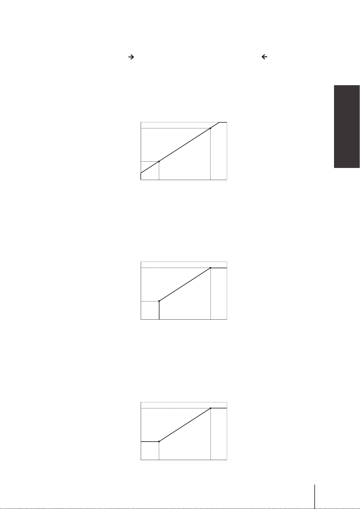
ANA. V (analogue variable) programming (see page 42 & 54)
The pump increases/decreases a stroke/ow rate in proportion to 0-20mA. Determine the operational behav-
iour by programming two set points and choosing one of the LINEAR, BOX and LIMIT patterns.
To show the current value, push the key. To return to the ow rate display, push the key.
<LINEAR>
A stroke/ow rate changes with a current value by a programmed line.
Condition:
Set Point 1 (SP.1) = Ampere : 6mA, Flow rate : 45L/H
Set Point 2 (SP.2) = Ampere : 17mA, Flow rate : 127L/H
150L/H
127L/H
SP.2
Overview
45L/H
0 6
SP.1
17
20mA
<BOX>
A stroke/ow rate changes with a current value by a programmed line. The rate does not exceed the Set Point
2 but then falls to 0 before the Set Point 1.
Condition:
Set Point 1 (SP.1) = Ampere : 6mA, Flow rate : 45L/H
Set Point 2 (SP.2) = Ampere : 17mA, Flow rate : 127L/H
150L/H
127L/H
45L/H
SP.1
0 6
17
SP.2
20mA
<LI M IT>
A stroke/ow rate changes with a current value by a programmed line. The rate does not falls below the Set
Point 1 or exceed the Set Point 2.
Condition:
Set Point 1 (SP.1) = Ampere : 6mA, Flow rate : 45L/H
Set Point 2 (SP.2) = Ampere : 17mA, Flow rate : 127L/H
150L/H
127L/H
45L/H
SP.1
0 6
17
SP.2
20mA
Operational functions
15
Page 16
■ Pulse control (see page 42 & 54)
The ow rate is automatically controlled by the ow volume (ml) per pulse and the pulse signal frequency from a
ow meter.
* It takes about 10 pulses for the IX to catch up with the change of the frequency.
10Hz 5Hz 10Hz
Pulse signal
Flow rate at 10Hz
Fow rate at 5Hz
0
Example of use: Chemical dosing in a sewage treatment system
Flow meter
Flow
Supply tank
Pulse signal
Pump
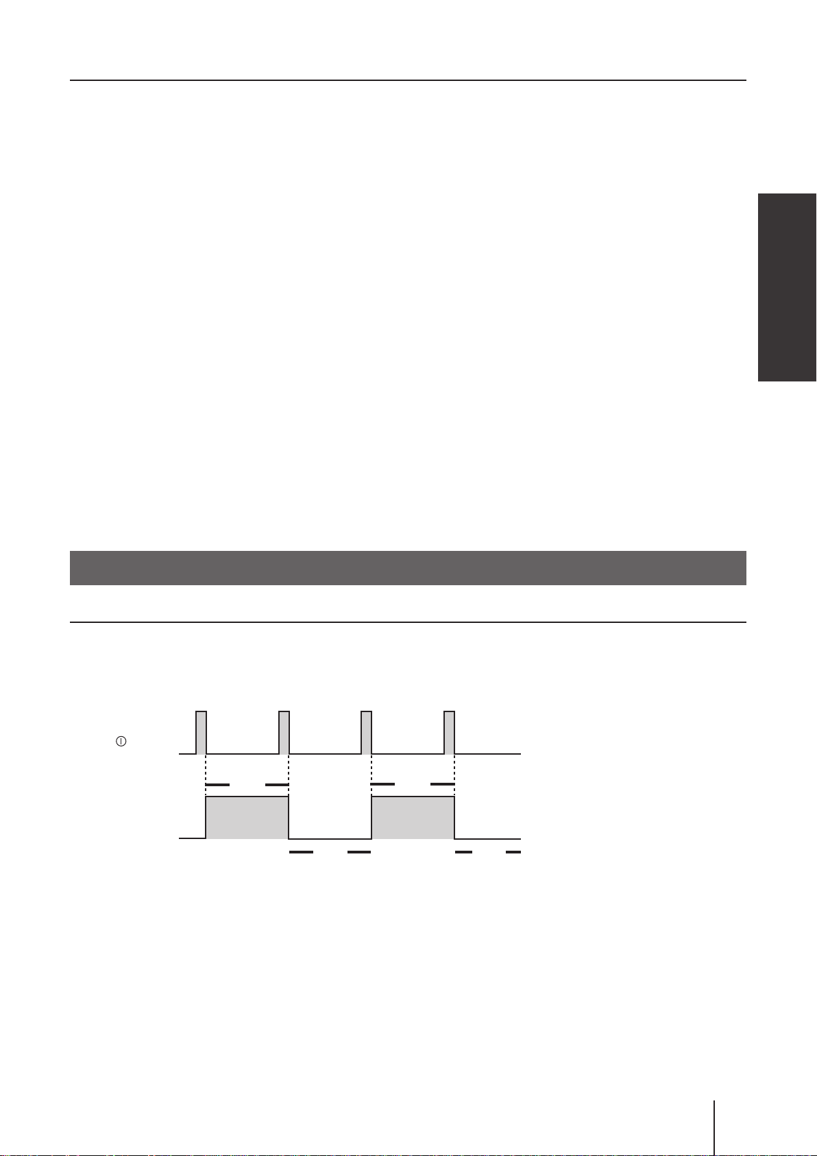
■ Batch control (see page 42 & 54)
The IX discharges a programmed ow volume per pulse and stops when it is completed. The programmed or
remaining ow volume is shown on the controller until it has reduced to zero. In this control mode, the pump
runs at the MAN speed (the pump speed in the manual mode). The pump behaviour can change depending on
the setting of the buffer. See below.
When the buffer is OFF:
Any input of the external pulse signal will be cancelled when the pump is activated for the earlier pulse input.
The next dosing becomes ready after the programmed ow volume has been completed.
*Note the control stops immediately when the key is pushed once.
Cancelled
Pulse input
Programmed
flow volume
Pump
Signal out
(batch comp alarm)
Operational functions
16
Run
Stop
Run
Run
Stop
Page 17
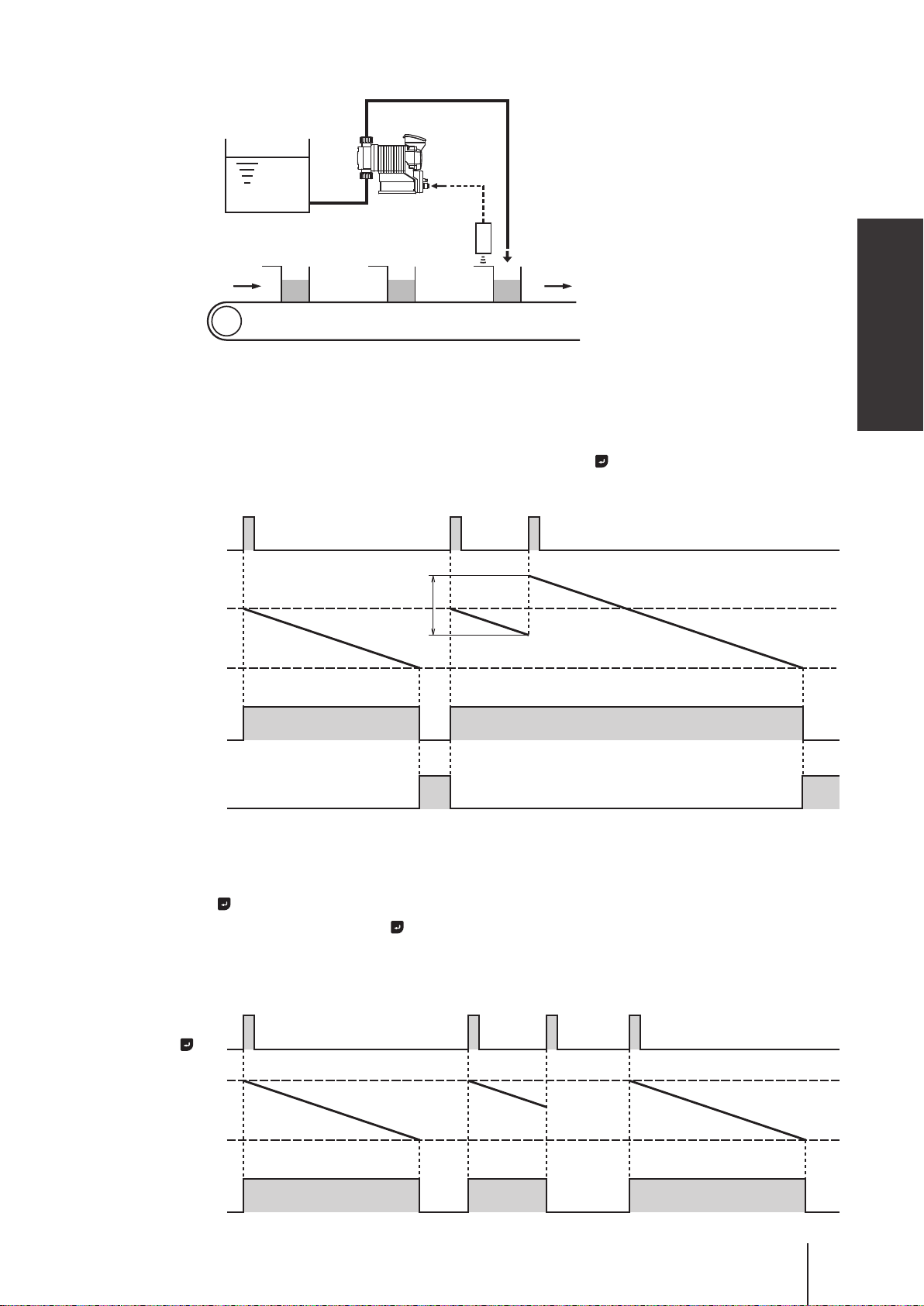
Example of use: Chemical dosing in a production line system
Supply tank
Pump
Pulse
signal
Proximity switch
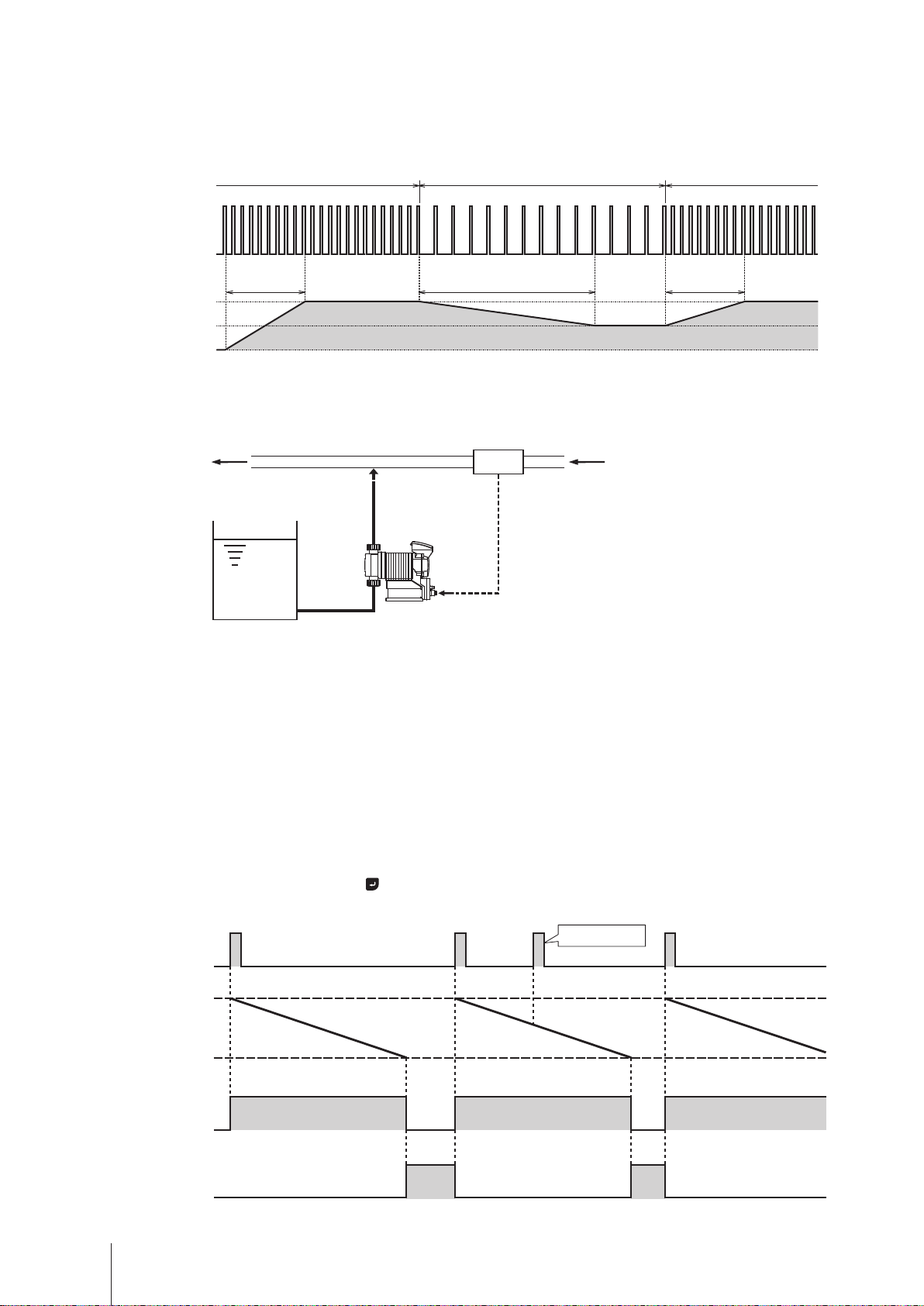
When the buffer is ON:
Every time the external pulse signal is inputted, the programmed ow volume per pulse is accumulated (max
65535 pulses) even when the pump is activated for the earlier pulse input.
*The control stops immediately and all the pulse accumulation is cleared when the key is pushed once.
Pulse input
Overview
Flow volume for
Programmed
flow volume
Pump
Signal out
(batch comp alarm)
the next signal
Run
Run
Stop Stop
Pulse input by the key:
Instead of the pulse signal input, pushing the key can start or stop the batch control. In this case, the pump
behaves as the control with the buffer OFF even when the buffer is set to ON in the batch control mode.
key
Programmed
flow volume
Pump
Run
Run
Stop Stop
Stop
Operational functions
Run
17
Page 18
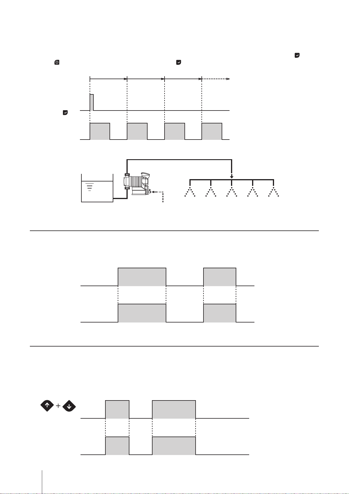
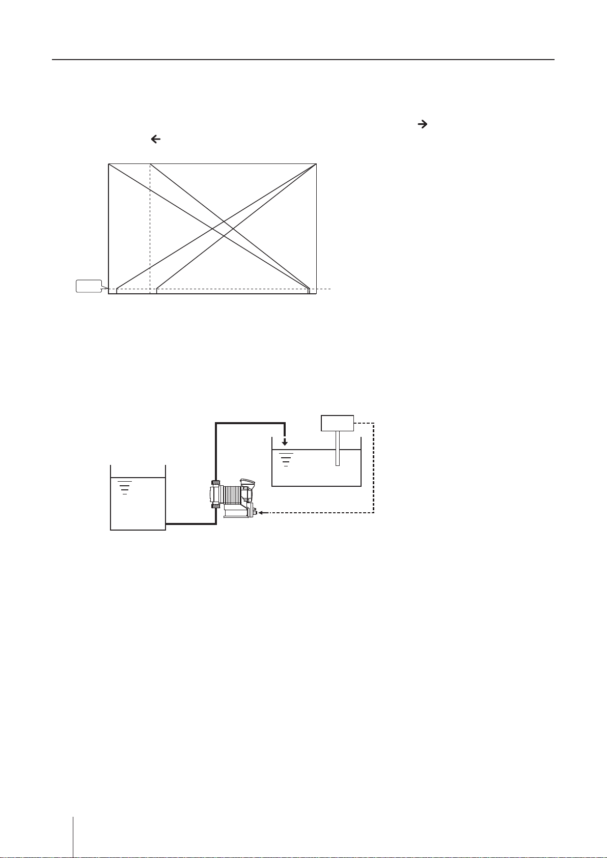
■ Interval batch control (see page 42 & 54)
To make an interval batch control, set a date and time interval and the ow volume. The IX discharges the pro-
grammed ow volume at a set interval. In the diagram below, the interval is set to 1 hour.
* The pump runs at the MAN speed. The control is triggered by either the external pulse signal or the push of the key.
Push the
key to stop the control when it is triggered by the key.
Time
Pulse signal/
Push of
key
Flow
1 hr
2 hr 3 hr
Example of use: Water transfer for a sprinkler system
Pump
Supply tank (water) Pulse signal
AUX function
The pump runs at the AUX speed while receiving the external signal via the AUX terminal. See page 51.
* This function works only when the pump is running in either MAN or EXT mode (see page 40.). The pump returns to the
MAN or EXT mode once the AUX signal stops.
AUX signal
Pump operation
RunStop RunStop
Priming function
The pump runs at the MAN speed (or the maximum stroke rate with default setting) while both the UP and
DOWN keys are pressed. Use this function for priming or degassing. Release both the keys to stop the pump.
See page 55 for detail.
* This function is available at any time except when the pump is in the MAN/EXT selection or menu selection (see page 40.).
Press & hold
Pump operation
RunStop Stop
Press & hold
Run Stop
Operational functions
18
Page 19
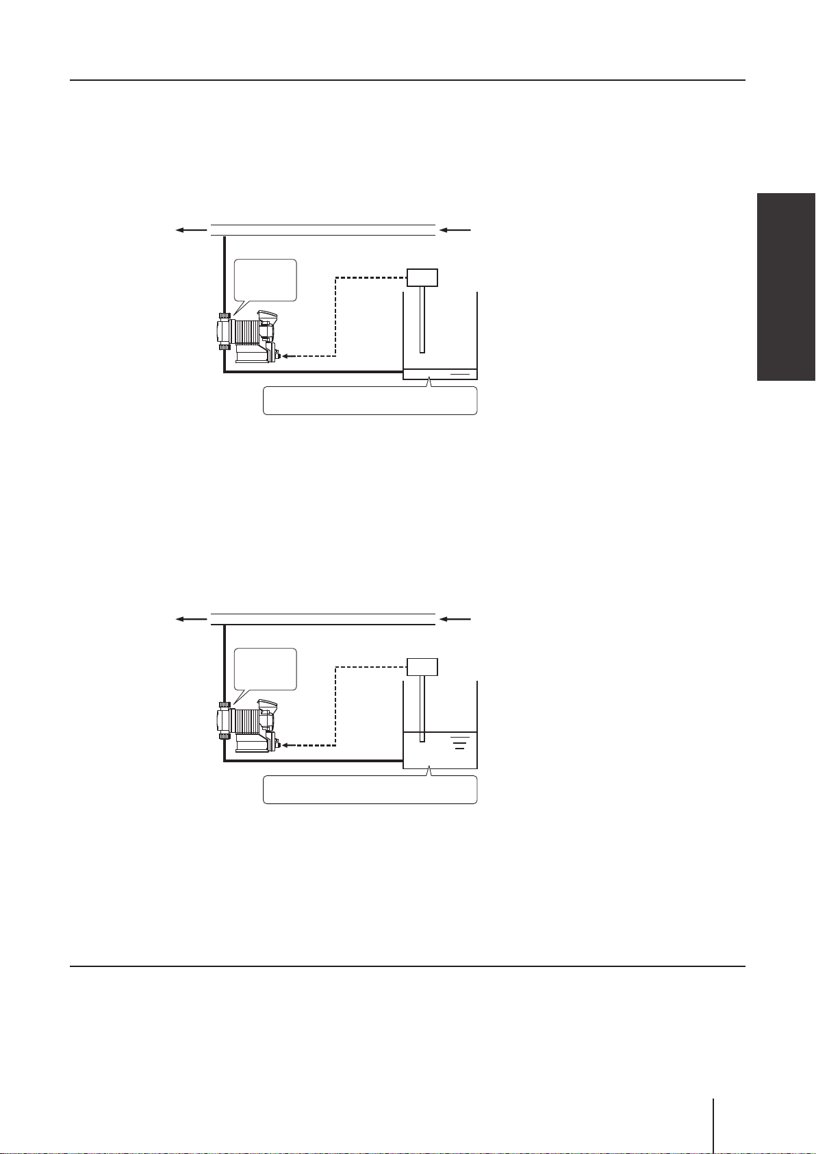
STOP functions
■ STOP function (see page 45)
The start/stop of operation can be controlled by the signal from a level sensor. The operation LED changes
from green to red colour when the pump is receiving the Pre-STOP signal from a level sensor in operation.
See page 32 "STOP IN" for wiring diagram.
Example of use: Liquid level monitoring
Flow
LED lights
in red
Pump OFF
Liquid is below the minimum level
The pump stops when liquid has fallen below the minimum level.
STOP signal
Level sensor
Overview
■ Pre-STOP function (see page 45)
Liquid level in the supply tank can be monitored by the signal from a level sensor. The operation LED changes
from green to orange colour when the pump is receiving the Pre-STOP signal from a level sensor in operation.
See page 32 "STOP IN" for wiring diagram.
Example of use: Liquid level monitoring
Flow
LED lights
in orange
Pump
ON
Liquid is near the minimum level
The operation LED lights in orange colour to inform a user that liquid comes
close to the minimum level in a supply tank.
Pre STOP
Level sensor
signal
Analogue output function
The pump transmits the 0-20mA analogue signal in proportion to the preset ow rates. See page 46.
Operational functions
19
Page 20
Protective functions
■ Interlock function (see page 32 & 47)
Interlock function works in the same way as the STOP function but uses a preference circuit. Use this function
for emergency stop.
■ Diaphragm rupture detection (see page 45)
The pump stops right after a built-in sensor detects a leak in the compartment at the back of the diaphragm. In
this condition, the operation LED lights in red colour. Replace a broken diaphragm as necessary. See page 63
for diaphragm replacement. To release this error condition, push the start/stop key (or the ESC key if the pump
is under the Probus control.).
NOTE
This capacitance sensor does not work properly if liquid conductivity is 1mS/m or below. Before sending pure
water, oil or any other low-conductivity liquid, check the conductivity to see if it meets the minimum detection
level. If it is not satised, the leak sensor is no longer usable. In this case a leak from the drain port is the
only valid indicator. In either case, replace the diaphragm immediately when a leak is found.
A leak is detected.
ON
Leak detection
OFF
Pump operation
Run Stop
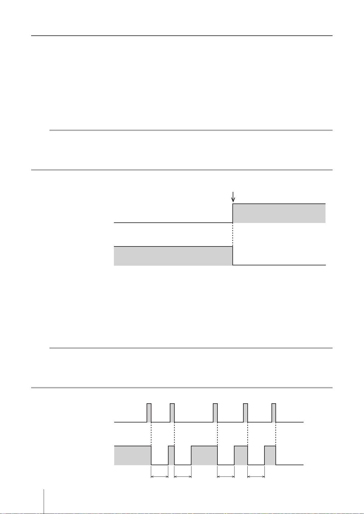
■ Pressure overload/Failed rotation control detection
The pump stops with the red operation LED blinking when a built-in pressure sensor detects 1.3-2.0 times high-
er discharge pressure than the maximum level or when the hole IC which monitors the motor rotation has failed.
If the pump is suspended (by the over-current protection) in either condition, the pump resumes operation 30
seconds later. If the suspended operation has recurred 5 times consecutively, the pump will not resume opera-
tion any more and will keep still. These error conditions can be released when the start/stop key is pushed once.
NOTE
The discharge pressure can rise 1.3-2.0 times higher than the maximum allowable level of the pump depending on operating conditions and piping layouts. Also, if the pressure rises too sharp (with the closed dis-
charge), it may not be even detected or curbed by the over-current protection. Set up a relief valve to protect
the related devices on the discharge line from the possible pressure rise if their pressure resistance is low.
ON
Overload detection
1 2 3 4 5times
Pump operation
20
Operational functions
OFF
Run Stop
30sec 30sec 30sec 30sec
Page 21

■ Alarm output function (see page 47)
Enable or disable the output of the batch completion, STOP, Pre-STOP, interlock, diaphragm rupture detection,
pressure overload detection, and/or drive error detection functions which is preset to the Alarm OUT 1 and 2,
or the output of the volume proportional pulse preset only to the Alarm OUT 2. See page 33 "Alarm OUT (DIN
connector)" for wiring diagram.
Alarm OUT 1 (OUT 1) : Mechanical relay output (no voltage contact 1a×1 250VAC 3A, resistive load)
Alarm OUT 2 (OUT 2) : PhotoMOS relay output (no voltage contact 1a×1 24VAC/DC 0.1A, resistive load)
Other functions
■ Suction speed setting (see page 51)
Suction speed is adjustable by 4 levels depending on liquid property. Reduce suction speed so as to reduce
inertia resistance for the delivery of viscous liquid or to prevent cavitation for gaseous liquid. Select 100% (de-
fault), 75%, 50% or 25%.
■ Maximum ow rate setting (see page 51)
The maximum allowable ow rate of the IX can be reduced if necessary. The default setting of the IX-C150 is
150L/H and the IX-C060 is 60L/H.
Overview
■ Diaphragm position adjustment (see page 51)
A pump shaft expands or contracts for easy diaphragm replacement. Select "MAX OUT Pos." through the
"Other Features" menu in order to extend the pump shaft to the maximum. Select "MAX IN Pos." to contract it
to the minimum and mount the pump head. See page 63 "Diaphragm replacement" for detail.
■ Anti chattering programming (see page 51)
Program a pulse recognition time for the IX not to be adversely affected by chattering or noise. Factory default
setting is 5 msec. This means the pump recognizes the pulse length of 5 msec or more. The other options are
1 and 2 msec and should be selected for the shorter pulse length, however, note the shorter the recognition
time is, the more susceptible to the interference of noise the pump becomes. Note the maximum allowable
input frequency of the IX is 100Hz.
■ Output logic setting (see page 51)
Select "normally open" or "normally closed" for the Alarm OUT 1 (OUT 1) and 2 (OUT 2) outputs.
■ Flow unit setting (see page 51)
Select L/H or GPH for the ow rate indication.
■ Language setting (see page 51)
Select your language through the language selection.
■ Keypad lock (see page 56)
The IX-C is shipped with the access codes at default values (00000). In order to prevent against unauthorized
tampering, you will need to change the access codes to your own values.
■ Default setting
Power on the pump while pressing the ESC key to recall default setting. Note the ow volume per shot ob-
tained through the calibration process (see page 37) remains the same.
Operational functions
21
Page 22
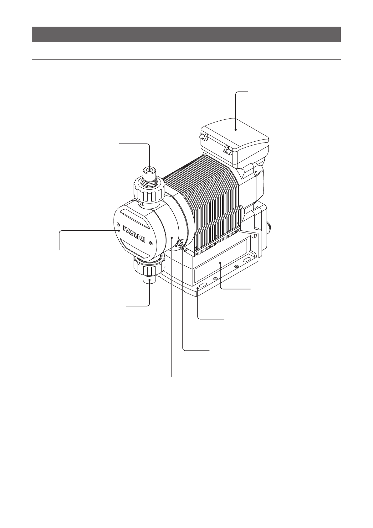
Part names
Pump
Control unit
Used for the start/stop of the pump
and operation control/program-
ming. See next page for detail.
Unhook the cover to open it. Push
down until it clicks once to close it.
Outlet
Bolt cover
Take out the cover to
remove the pump head.
Inlet
Pump head
Nameplate
Describes the pump specifi-
cations.
Base
Always anchor it with bolts.
Drain port (Vent hole)
Chemical liquid will be released from here.
* Do not plumb this drain port to a supply tank
with sodium hypochlorite or any other strong
acid. Make sure this port "breathes" in a clean
atmosphere.
22
Part names
Page 23
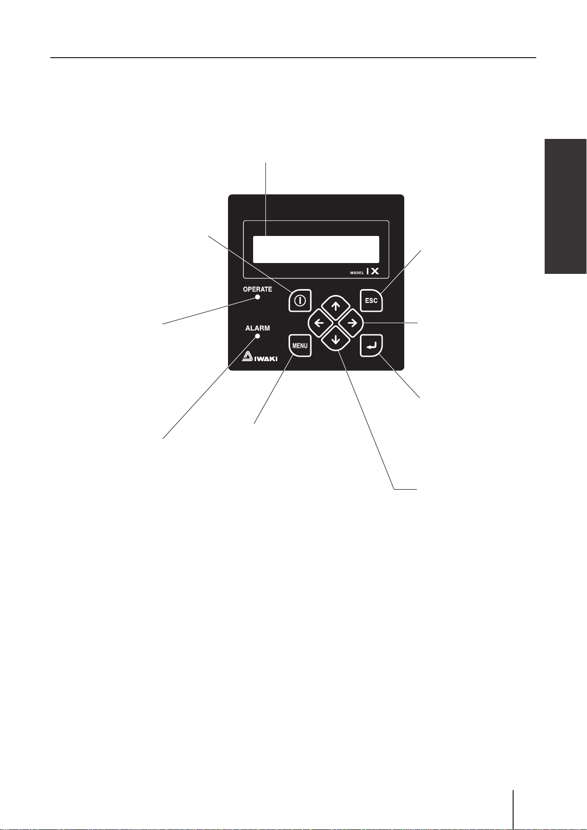
Operation panel
Start/Stop key
Used for starting/stopping the pump
operation or moving back to the MAN/
EXT selection.
Display
An operational status, a selected mode
and programmed values are shown here.
Overview
ESC key
Used for cancelling pro-
gramming and moving back
to a previous menu.
Operation LED
Lights in green in operation
and in red during stoppage,
programming, error conditions.
Lights in orange as Pre-STOP
signal is entered. See page 24.
ALARM LED
Lights to notice the damaged diaphragm, the inter-
lock activation or so.
MENU key
Used in the MAN/EXT
selection screen for calling
up the menu screen.
Left/Right key
Used for moving through
items. Press and hold both
keys for 3 seconds to dis-
able keypads.
Enter key
Used for making a deci-
sion in the menu screen or
MAN/EXT selection.
UP/DOWN key
Used for changing numeric
values or selecting a programming mode.
The pump enter the priming
mode while both the keys
are pressed.
Part names
23
Page 24
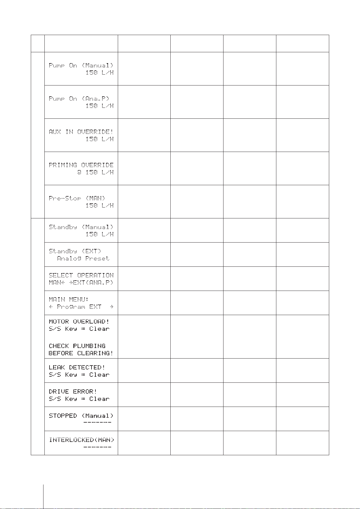
■ Basic displays & Pump states
Display
Operation LED
lights in red
Operation LED
lights in green
Operation LED
lights in orange
ALARM LED
lights in red
Operation
―
―
― AUX operation ― ―
―
― ―
A wait state in
manual mode
Operation in
manual mode
Operation in EXT
mode (Analogue
control)
Operation in prim-
ing mode
― ― ―
― ―
― ―
― ―
Pre-STOP func-
tion is active.
Pre-STOP func-
tion is active.*
A wait state in
EXT mode (ana-
logue control)
MAN/EXT selec-
tion
Menu screen ― ― ―
Pressure overload
Stop
or
protection is ac-
tive.
Diaphragm is bro-
ken.
Failed rotation
control is detected.
Operation stop in
manual mode
― ― ―
― ― ―
Pressure overload
― ―
― ―
― ―
― ―
protection is ac-
tive.*
Diaphragm is bro-
ken (Alarm OUT 1
default setting).*
Failed rotation
control is detect-
ed.*
Operation stop in
manual mode*
― ― ―
* The Alarm LED becomes active when a function is allocated to the Alarm OUT 1 or 2.
Part names
24
Interlock function ac-
tivation (Alarm OUT
2 default setting)*
Page 25
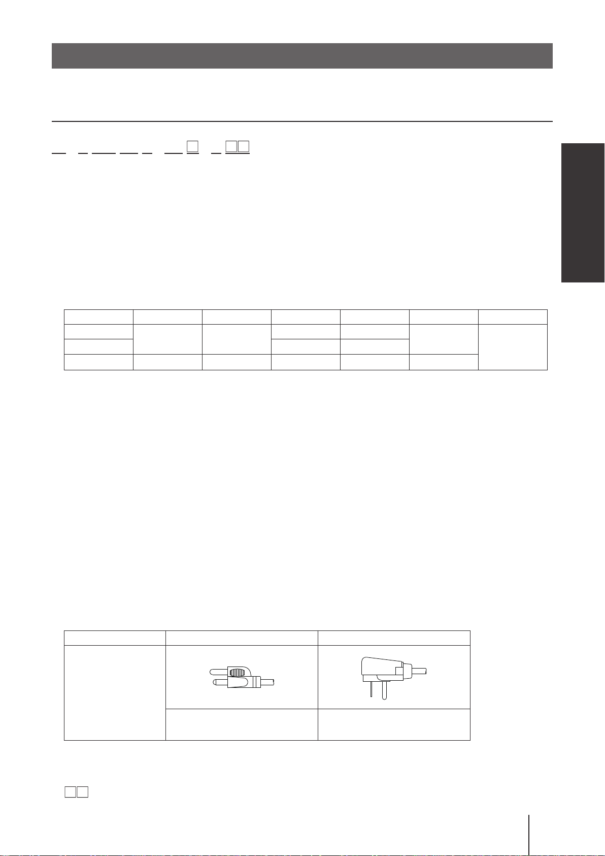
Identication codes
Each code represents the following information.
Pump
IX - C 150 TC N - TB - U
a b c d e f g h i
a. Series name
b. Drive unit
c. Pump unit (Max ow)
150 : 150 [L/H]
060 : 60 [L/H]
d. Wet end materials
Code Pump head Ball valve Valve seat O ring Valve gasket Diaphragm
TC
TE EPDM EPDM
S6 SUS316 SUS316 SUS316
*EPDM is not a wet end.
PVDF CE
FKM FKM
―
―
PTFE
Overview
PTFE+EPDM*
Material code
PVDF : Polyvinylidene diuoride PTFE : Polytetrauoroethylene
EPDM : Ethylene-propylene rubber FKM : Fluorine-contained rubber
CE : Ceramics SUS316 : Austenite stainless
e. Connection
N : NPT thread
FA : ANSI ange
f. Controller housing
TF : Top Front TB : Top Back TR : Top Right TL : Top Left RF : Right Face LF : Left Face
g. Control code
1 : IX-C060
2 : IX-C150
h. Power plug
Code U U2
Plug shape
115V (1950mm length) 230V (1950mm length)
i. Special version
No code : Standard models
: Customized models will be coded.
Identication codes
25
Page 26
Installation
This section describes the installation of the pump, piping and wiring.
Read through this section before work.
Points to be observed
Observe the following points when installing the pump.
• Risk of electrical shock. Be sure to turn off power to stop the pump and related devices
before service is performed.
If you notice any abnormal or dangerous conditions, suspend operation immediately and
•
inspect/solve problems.
• Do not place explosive or ammable material near the pump.
• Use of a damaged pump could lead to an electric shock or death.
Pump mounting
Select an installation location and mount the pump.
Necessary tools
• Four M8 bolts (pump mounting) • Adjustable wrench or spanner
Select a suitable place.
1
Always select a at oor free of vibrations. See page 10 for detail.
Anchor the pump by four M8 bolts.
2
Be sure to x the pump at four points.
NOTE
Select a level location, or the ow may reduce.
Pump mounting
26
Page 27
Pipework
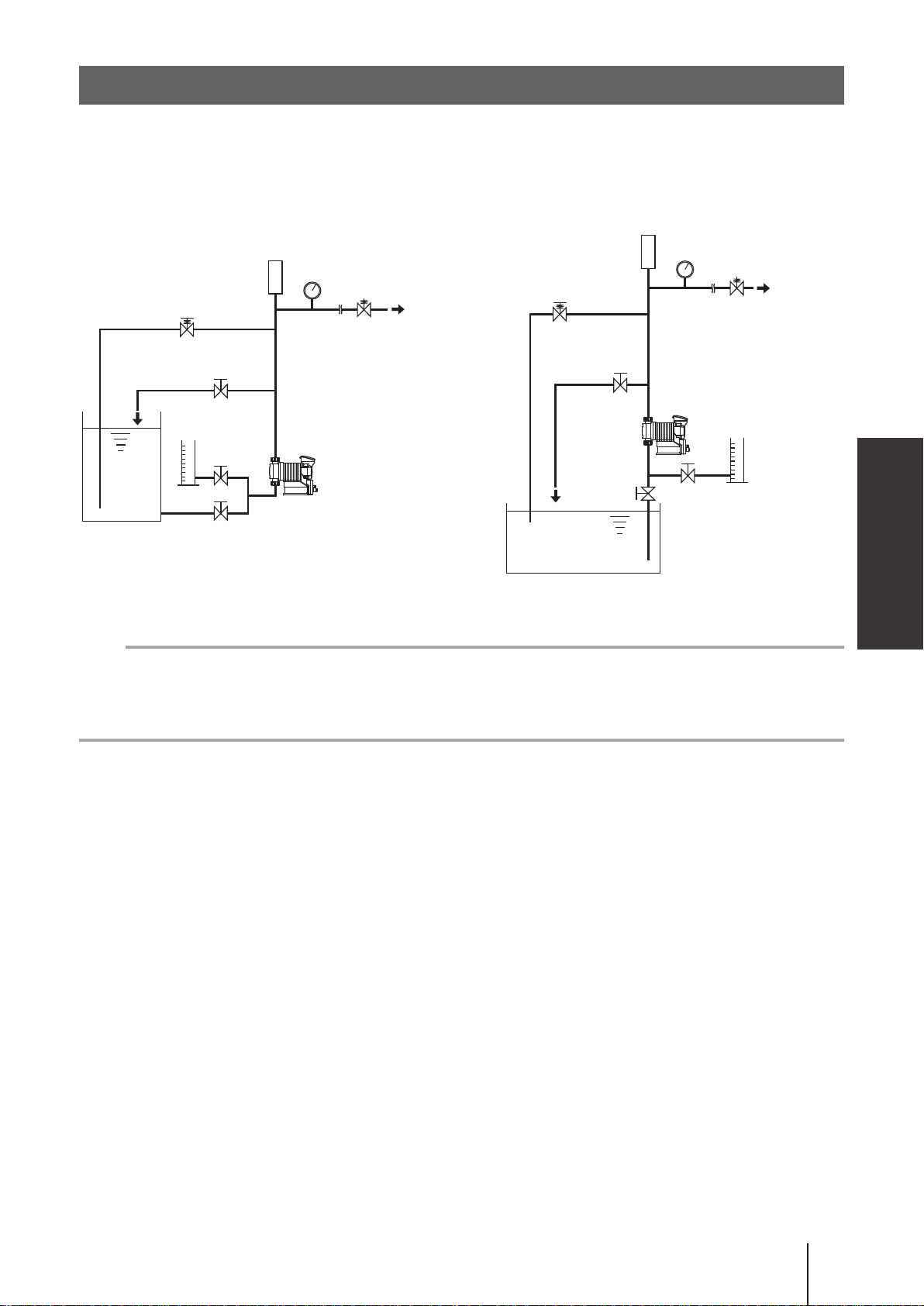
■ Piping layout
Flooded suction application Suction lift application
Accumulator/Chamber
Accumulator/Chamber
Pressure gauge
Relief valve
Back pressure valve
Air vent/drain valve
Calibration
cylinder
Pump
Tank
Relief valve
Air vent/
drain valve
Pump
Pressure gauge
Back pressure valve
Installation
Calibration
cylinder
Tank
NOTE
• The suction line I.D. should be equal to or wider than the I.D. of the pump.
• When handling liquids that generate gas bubbles (sodium hypochlorite or hydrazine solution), install the pump
in a cool and dark place. Flooded suction installation is strongly recommended.
Pipework
27
Page 28

Drain port (Vent hole)
Leaked liquid drains through the drain port at the time of accidental diaphragm rupture.
Use an appropriate chemically-resistant tube to the port to safely collect the liquid.
NOTE
• Do not plug the drain port. The port functions as a vent hole to keep the pressure behind the diaphragm back
atmospheric.
• Do not immerse the end of a drain tube in drained liquid, or the liquid may be pumped up into the compart-
ment behind the diaphragm back.
• Liquid in the drain tank is the sign of the damaged diaphragm. Immediate inspection or repair is necessary.
Do not leave this condition as it is. Fumes or vapors from certain solutions may move up into the pump via the
drain tube and attack its inside.
(20)
Do not locate the drain tube
end below the liquid level.
Drain port (vent hole)
*Applicable tube size
Empty drain tank
Inner diameter: 6mm
Outer diameter: 12mm or below
Noncorrosive chemicals in a
supply tank. The drain tube end
must stay above the liquid level.
6)
ø
(
7.5)
ø
(
Do not take in fumes from
corrosive chemicals such as
sodium hypochlorite.
Drain port (Vent hole)
28
Page 29

Wiring
Wiring for power voltage, earthing and external signals.
Points to be observed
Observe the following points during wiring work.
Electrical work should be performed by a qualified electrician. Always observe applica-
•
ble codes or regulations.
Do not apply power other than that specified on the nameplate. Otherwise, failure or fire
•
may result.
Do not perform wiring work while electric power is on. Otherwise, an electrical shock or
•
a short circuit may result. Be sure to turn off the power before wiring work.
Be careful for electric power not to be turned on during work.
•
Replacement of a power cable should be conducted by a manufacturer, his agency or a
•
skilled person. Otherwise, an accident may result.
End terminals
Installation
See the following diagram for detail.
Alarm OUT
EXT IN
STOP IN
AUX IN/Analog OUT
Fieldbus
Power cable (1950mm)
Wiring
29
Page 30

Power voltage/Earthing
Points to be checked
• Check that power voltage is turned off.
Insert the plug all the way seated in a socket.
1
NOTE
• Do not share a power source with a high power device which may generate a surge voltage. Otherwise an
electronic circuit may fail. The conductive noise caused by an inverter also affects the circuit.
• Energize the pump with a power voltage via a mechanical relay or switch. Do not uctuate the voltage, or
CPU may malfunction. See page 31 for the precautions for ON-OFF control by a mechanical relay.
Apply power sharply Do not apply gradually
POWER
ON
OFF
POWER
TIME
ON
OFF
TIME
Surge voltage
The electronic circuit in the control unit may fail due to a surge voltage. Do not place the
pump close to a high power device of 200V or more which may generate a large surge
voltage. Otherwise, take any of the following measures.
• Install a surge absorption element (such as a varistor with capacity of 2000A or more)
via power cable or,
Surge absorption element
Recommended varisters:
Panasonic ER ZV14D431
KOA NVD14UCD430
See manufacturer's catalogues for detail.
A noise cut transformer via the power cable.
•
Noise cut transformer
Wiring
30
Page 31

Precautions for ON-OFF control by a mechanical relay
The control unit is equipped with a CPU. To ensure the CPU to work properly, always
start/stop the pump by the STOP signal for ON-OFF control. Try not to turn on and off the
main power. Otherwise, observe the following points:
• Ensure the minimum OFF time of 10 minutes.
• The contact capacity of a mechanical relay should be 5A or more. Or a contact point
may break.
• If the contact capacity of a mechanical relay is 5A, the maximum allowable number of
times the power is turned ON/OFF is 150,000. The contact capacity should be 10A or
more when the actual number of times is over 150,000 or when sharing a power source
with a large capacity equipment which may cause a surge voltage and damage a con-
tact point.
• Use a solid state relay (SSR) as necessary (such as the OMRON G3F). See manufac-
turer's catalogues for detail.
Signal wire connection
Installation
Points to be checked
• Check that power voltage is turned off.
Use our optional connector cables below or purchase DIN 4- and 5-pin female connector cables when using
signal input and output.
Optional 5m DIN connector cables for:
The EXT input signal
The STOP input signal
The AUX input/Analog output signals
The Alarm output signal
NOTE
• Do not lay on these signal cables in parallel with a power cable. Otherwise the electromagnetic induction
noise is generated and malfunction or failure may result.
• The following products are the recommended SSRs (Solid State Relays) for signal input. Any other SSRs
might cause malfunction. See manufacturer's information for details on these SSRs.
–OMRON G3FD-102S or G3FD-102SN
–OMRON G3TA-IDZR02S or G3TA-IDZR02SM
• When using a mechanical relay for signal input, its minimum application load should be 5mA or below.
• Insert the DIN 4- or 5-pin female connector as far as it will go and then tighten the skirt to make a secure con-
nection.
*Use either a no-voltage contact or an open collector for the EXT signal.
Wiring
31
Page 32

■ EXT IN
To make pulse-, batch-, interval batch- and analogue-control operation or to activate interlock function, connect
signal wires to the EXT terminals via the DIN 5-pin connection.
When using an open collector:
Pay attention to polarity. Pulse (1) and Interlock (2) are plus (+), and COM (4) is minus (-).
When using analogue control:
Pay attention to polarity. Analogue (3) is plus (+) and COM (4) is minus (-). Internal resistance is 200Ω.
When using a no-voltage contact:
Use a mechanical relay designed for an electronic circuit. Its minimum application load should be 5mA or less.
2
3
1
5
4
2
3
1
5
4
2
3
1
5
4
1 : Pulse (Brown)
2 : Interlock (White)
3 : Analogue (Blue)
4 : COM (Black)
5 : 12VDC30mA or below (Green)
* Each wire is coloured as above for
our optional cable. The terminal
5 is an output and is not used. Do
Wiring for
Pulse-, Batch-, Interval
batch-control
Wiring for
Analogue control
Wiring for
Interlock function
not short-circuit this terminal to
COM (4).
■ STOP IN
To activate STOP function, connect signal wires to the STOP terminal via the DIN 4-pin connection.
When using an open collector:
Pay attention to polarity. STOP (1) and Pre-STOP (2) are plus (+), and COMs (3 and 4) are minus (-).
When using a no-voltage contact:
Use a mechanical relay designed for an electronic circuit. Its minimum application load should be 5mA or less.
2
2
1 : STOP (Brown)
2 : Pre-STOP (White)
3
1
3
1
3 : COM (Blue)
4 : COM (Black)
4
Wiring for
STOP function
Wiring for
Pre-STOP function
4
* Each wire is coloured as above for our optional cable.
NOTE
Our optional cable has 5 wires. Cut off a green wire to use it with the DIN 4-pin connector.
Wiring
32
Page 33

■ AUX IN/Analog OUT
To activate the AUX function or to use the analogue output, connect signal wires to the AUX terminal or the
4-20mA output terminal via the DIN 5-pin connection.
When using an open collector (for AUX IN):
Pay attention to polarity. AUX (3) is plus (+), and COM (4) is minus (-).
When using a no-voltage contact (for AUX IN):
Use a mechanical relay designed for an electronic circuit. Its minimum application load should be 5mA or less.
When using analogue output:
Pay attention to polarity. The 0-20mA (1) is minus (-) and 0-20mA (5) is plus (+). The max load resistance is 300Ω.
2
3
5
4
Wiring for
AUX function
2
1
3
5
4
Max.300Ω
Wiring for
4-20mA output
1
1 : 0-20mA (Brown)
2 : N.C. (White)
3 : AUX (Blue)
4 : COM (Black)
5 : 4-20mA (Green)
* Each wire is coloured as above for our optional cable.
■ Alarm OUT (DIN connector)
To transmit the signal to an external device, connect signal wires to the OUT terminal via the DIN 4-pin connection.
Alarm OUT 1 (OUT 1) <Mechanical relay>: Enable or disable the alarm outputs of batch completion,
STOP, Pre-STOP, interlock, motor overload (/drive error) and leak detection individually.
*Leak detection only is enabled at factory default setting.
Alarm OUT 2 (OUT 2) <PhotoMOS relay>: Enable or disable the alarm outputs of the volume proportional pulse, batch completion, STOP, Pre-STOP, interlock, motor overload (/drive error) and leak
detection individually.
*Interlock only is enabled at factory default setting.
Installation
4
1
3
2
1 : Alarm OUT 1 (White)
2 : Alarm OUT 1 (Brown)
3 : Alarm OUT 2 (Black)
4 : Alarm OUT 2 (Blue)
* Each wire is coloured as above for our optional cable.
Mounting direction of the output signal cable
Mount the DIN square connector cable in the following direction and secure it with a M3 screw.
Alarm OUT terminal
Gasket
Output signal cable
M3 screw
Wiring
33
Page 34

Operation
This section describes pump operation and programming. Run the pump
after pipework and wiring are completed.
Before operation
First check piping and wiring are correct. And then make commissioning before starting operation.
Points to be checked
Before operation, check if:
• Liquid level in a supply tank is enough.
• Piping is securely connected and is free from leakage and clogging.
• Discharge/suction valves are opened.
• Power voltage range is correct.
• Electrical wiring is correct and is free from the risk of short circuit and electrical leakage.
Retightening of pump head xing bolts
Important
The pump head xing bolts may loosen when plastic parts creep due to temperature change in storage or in
transit, and this can lead to leakage. Be sure to retighten the bolts evenly to the specied tightening torque
below in diagonal order before starting operation.
Tightening torque
Model code Tor q u e Bolts Number of bolts
IX-C150 12 N•m M8 hexagon head bolt 8
IX-C060 3.5 N•m M5 hexagon head bolt 6
*Tighten xing bolts once every three months.
Before operation
34
Page 35

Commissioning
Always make commissioning when rst mounting the pump in your system or resuming operation after a long
period of stoppage.
1
Open an air vent and a suction line.
Do not open a calibration line if any.
Air vent valve
Open
Close
Open
Supply the rated power voltage to the pump.
2
3
Start the pump at a low ow rate and gradually increase it to a target rate.
Continue operation for 10 minutes and check the pump and pipework for any abnormality.
4
Close an air vent line to introduce liquid to a main line.
Before a long period of stoppage (One month or more)
Clean wet ends and the inside of piping.
• Run the pump with clean water for about 30 minutes to rinse chemicals off.
Before unplugging the pump
• Always stop the pump by key operation and wait for three seconds before unplugging the pump. Otherwise,
the last key operation may not be put in memory. In this case the pump unintentionally starts to run as pow-
ered on, discharging liquid.
Operation
When the pump does not transfer liquid at resuming operation.
• Clean the valve sets and remove foreign matters.
• If air is in the pump head, expel air through the above commissioning procedure.
Before operation
35
Page 36

Perform a calibration
Periodically make calibration to monitor an accurate ow through control display.
The pump is calibrated by pumping clean water at the maximum operating pressure before
shipping (in the absence of a designation by a user), however, make calibration again in an
actual operating condition as necessary. Follow the calibration process on the next page.
NOTE
The ow rate shown on the screen is a calculated value based on calibration and is not an actual ow rate.
Calibration is made to determine liquid volume per shot. Arrange your piping system according to the guide
below to ensure the calibration is made correctly.
Suggested piping layout
Use a calibration cylinder connected to a suction line.
Accumulator/Chamber
Pressure gauge
Relief valve
Back pressure valve
Air vent valve
Calibration
cylinder
Pump
Tank
Bad example
Do not immerse a calibration tube in liquid level in a calibration cylinder. Otherwise, tube volume is added to
the liquid volume to be measured, and calibration will be upset.
Tank
Calibration
cylinder
Pump
36
Perform a calibration
Before calibration
Tube in liquid
After calibration
Calibration cylinder
Page 37

Calibration process
Obtain accurate ow volume per shot (e.g. about 16ml/shot for the C150 type, about 6ml/shot for the C060
type) by dividing the delivered liquid volume by the number of strokes.
Fill a calibration cylinder with liquid.
1
Open a calibration line to lead liquid from a supply tank to a calibration cylinder. And then close the suc-
tion line and measure liquid volume in the cylinder.
Air vent valve
Open
Close after the cylinder is filled with liquid.
Supply the rated power voltage to the pump and programme a ow rate in the manual
2
mode.
See page 13 for detail.
NOTE
The calibration accuracy won't change at any ow rate. The higher the ow rate is, the shorter time it
takes, and vice versa.
3
Select the calibration mode through the menu screen.
See page 44 for detail.
Calibration operation programming
4
Set a waiting time and the number of strokes. The number of strokes should be determined depending
on how much liquid remains in the calibration cylinder.
Waiting time to start calibration operation : 10(default)-999s
Number of strokes : 60(default)-120ST
Operation
Use UP and DOWN keys to set a waiting time.
Use UP and DOWN keys to set the number of strokes.
Perform a calibration
37
Page 38

5
Start calibration operation.
Push the Enter key after setting the number of
strokes. The pump starts the countdown.
Pump
starts
Pump
stops
Measure liquid volume in the calibration cylinder again.
6
Enter how much liquid has reduced.
7
Use the UP and DOWN keys to set the volume reduction.
The pump starts to run for the set number of
strokes as it comes to zero.
Push the Enter key once. The screen shows ow volume
per shot.
The screen shows "ERROR! Volume Out Of Range!!" if
the reduction is too little or too large. Enter correct liquid
volume or recalibrate it.
NOTE
Calibration with high viscosity liquid at a full suction
speed will often give rise to this error. Reduce a suction
speed along with viscosity.
Push the ESC key to return to the wait mode.
Perform a calibration
38
Page 39

Operation programming
The setting is made with the controller. The pump behaviour differs with each control mode.
Menu Control mode/Function Parameter Default
Mode se-
lection
Analog preset control 0 - 20mA/ 4 - 20mA/ 20 - 0mA/ 20 - 4mA 4-20mA
Analog variable con-
trol
External
control
Signal input
Alarm
Analogue output
Others
* For these control modes, the calibrated ow volume per shot is applied to the minimum settable ow volume.
Pulse control*
Batch control*
Interval batch control*
Probus control Address : 1 - 126 50
STOP Closed = Pump OFF/ Closed = Pump ON Closed = Pump OFF
PreSTOP Closed = Pump OFF/ Closed = Pump ON Closed = Pump OFF
Interlock Closed = Pump OFF/ Closed = Pump ON Closed = Pump OFF
Leak detection Enable/ Disable Enable
OUT 1
OUT 2
Suction speed 100%/ 75%/ 50%/ 25% 100%
Maximum ow rate
AUX speed
Diaphragm position MAX OUT Pos./ MAX IN Pos. MAX OUT Pos.
Buffer Enable/ Disable Disable
Anti-Chattering 1msec/ 2msec/ 5msec 5msec
Output logic (OUT 1) Normally Open/ Normally Close Normally Open
Output logic (OUT 2) Normally Open/ Normally Close Normally Open
Unit Litter/ US gallon Litter
Keypad lock 00000 - 99999 00000
Language English/Dutch/French/Danish/Spanish/German English
- MAN/EXT MAN
SP1 current 0.0 - 20.0mA 4.0mA
SP1 ow rate
SP2 current 0.0 - 20.0mA 20.0mA
SP2 ow rate
0.00625mL/PLS - 120mL/PLS (C060) 0.00625mL/PLS
0.0156mL/PLS - 300mL/PLS (C150) 0.01562mL/PLS
6.25mL/PLS - 120L/PLS (C060) 6.25mL/PLS
15.6mL/PLS - 300L/PLS (C150) 15.62mL / PLS
0 - 9day, 0 - 23Hr, 1 - 59min 0D : 0H : 1M
6.25mL - 120L/PLS (C060) 6.25mL/PLS
15.6mL - 300L/PLS (C150) 15.62mL / PLS
Batch Complete/ STOP/ Pre-STOP/ Interlock/
Leak Detection/ Motor Overload/ Drive Error
Volume Prop. PLS/ Batch Complete/ STOP/
Pre-STOP/ Interlock/ Leak Detection/ Motor
Overload/ Drive Error
SP1 current 0.0 - 20.0mA 4.0mA
SP1 ow rate
SP2 current 0.0 - 20.0mA 20.0mA
SP2 ow rate
80mL/H - 60L/H (C060) 60L/H
200mL/H - 150L/H (C150) 150L/H
80mL/H - 60L/H (C060) 60L/H
200mL/H - 150L/H (C150) 150L/H
0mL/H - 60L/H (C060) 0mL/H
0mL/H - 150L/H (C150) 0mL/H
0mL/H - 60L/H (C060) 60L/H
0mL/H - 150L/H (C150) 150L/H
Leak Detection: Enable
Other alarms: Disable
Interlock: Enable
Other alarms: Disable
0mL/H - 60L/H (C060) 0mL/H
0mL/H - 150L/H (C150) 0mL/H
0mL/H - 60L/H (C060) 60L/H
0mL/H - 150L/H (C150) 150L/H
Operation
Operation programming
39
Page 40

Programming ow
Power ON
MAN/EXT selection
Wait state
Operation
or
or
Menu screen
MAN modeEXT mode
MAN modeEXT mode
Use keys to scroll.
* See page 41 for setting at each menu.
* To revert back to the default setting with the pump calibrated, turn on power while pressing the ESC key.
Operation programming
40
Page 41

Menu screen
Push the MENU key in the MAN/EXT selection mode and call up the menu screen. Use the right and left keys
to scroll through each menu item and then push the Enter key to make a selection. Pushing the MENU key
again or ESC key in the menu screen, the previous mode will be recalled.
EXT mode selection
The pump can run in four different operating modes of Analogue,
Pulse, Batch and Interval Batch for the external signal. See page
14-18 and 42 for detail.
Calibration
Calibrate the pump to obtain a correct ow rate on the screen.
See page 37 and 44.
Signal input setting
Program STOP, Pre-STOP, Interlock functions and diaphragm
rupture detection. See page 19, 20, 45 and 46.
Analog output setting
Set the output current at SP1 and 2 ow rates to congure the
analog signal output behaviour. See page19 and 46.
Alarm output setting (OUT 1)
Enable or disable the output of the batch completion, STOP,
Pre-STOP, interlock, diaphragm rupture detection, overload/failed
speed detection, and/or drive error detection functions. See page
21 and 47.
Alarm output setting (OUT 2)
Enable or disable the output of the batch completion, STOP,
Pre-STOP, interlock, diaphragm rupture detection, overload/failed
speed detection, drive error detection, and/or volume proportional
pulse functions. See page 21 and 49.
Data logging
The pump can display operating time, total ow volume, power-on
time, the number of ON/OFF and software version. See page 50.
Operation
Programming of other functions
Program a suction speed, a max ow rate, an AUX speed, a dia-
phragm position, an anti-chattering time, butter ON/OFF, output
logics, a ow rate unit and your language or so. See page 21, 51,
52 and 53.
Operation programming
41
Page 42

■ EXT mode selection
key to confirm
key to return to menu screen
key to scroll
key to change values
Mode selection screen
Analogue preset
Analogue variable
Pulse control
Batch control
Interval batch control
Profibus control
Analogue preset control
Mode setting screen
Operation programming
42
<To next page>
Page 43

Analogue vairable control
SP1 current setting
SP1 flow rate setting
SP2 current setting
to change the value
to change the value
to change the value
SP2 flow rate setting
Behavioural pattern selection
Pulse control
to change the value
Operation
to select the pattern
Set flow volume per pulse.
Batch control
Set flow volume per pulse.
<To next page>
Operation programming
43
Page 44

Interval batch control
Profibus control
Set “Day”.
Set “Hour”.
Set “Minute”.
Set a flow rate.
■ Calibration
key to confirm
key to return to menu screen
Set an address.
*See page 37 "Calibration process" for detail.
key to select
key to change values
Operation programming
44
Page 45

<To next page>
■ Signal input setting
key to confirm
Function selection screen
STOP function
Pre-STOP function
key to return to menu screen
key to scroll
key to change values
Interlock function
Diaphragm rupture detection
Function setting screen
STOP function
Closed=Pump OFF : Pump stops running
at contact input.
Closed=Pump ON : Pump starts to run at
contact input.
Operation
Pre-STOP function
Interlock function
Closed=Pump OFF : Operation LED lights in
orange at contact input.
Closed=Pump ON : Operation LED does not
lights at contact input.
Closed=Pump OFF : Pump stops running
at contact input.
Closed=Pump ON : Pump starts to run at
contact input.
Operation programming
45
Page 46

Diaphragm rupture detection
Disable : Rupture detection is not
used.
Enable : Rupture detection is used.
■ Analogue output setting
key to confirm
key to return to menu screen
key to scroll
key to change values
Function selection screen
SP1 current setting
to change the value
SP1 flow rate setting
to change the value
SP2 current setting
to change the value
Operation programming
46
SP2 flow rate setting
to change the value
Page 47

■ Alarm output setting (OUT 1) <Mechanical relay>
Output selection screen
Batch completion
STOP function
key to confirm
key to return to menu screen
key to scroll
key to change values
Drive error
Pre-STOP function
Overload detection
Interlock function
Diaphragm rupture detection
Operation
Batch completion
STOP function
Output setting screen
Disable : OUT1 is inactive.
Enable : OUT1 is activated at input
of the completion signal.
Disable : OUT1 is inactive.
Enable : OUT1 is activated at input
of STOP signal.
<To next page>
Operation programming
47
Page 48

Pre-STOP function
Interlock function
Diaphragm rupture detection
Disable : OUT1 is inactive.
Enable : OUT1 is activated at input
of Pre-STOP signal.
Disable : OUT1 is inactive.
Enable : OUT1 is activated at input
of interlock signal.
Disable : OUT1 is inactive.
Enable : OUT1 is activated at input
of the detection signal.
Overload/Failed speed detection
Drive error detection
Disable : OUT1 is inactive.
Enable : OUT1 is activated at input
of the detection signal.
Disable : OUT1 is inactive.
Enable : OUT1 is activated at input
of the detection signal.
48
Operation programming
Page 49

■ Alarm output setting (OUT 2) <PhotoMOS relay>
Output selection screen
Volume proportional pulse
Batch completion
key to confirm
key to return to menu screen
key to scroll
key to change values
Drive error
STOP function
Overload detection
Pre-STOP function
Interlock function
Operation
Diaphragm rupture detection
Output setting screen
Volume proportional pulse
Disable : OUT2 is inactive.
Enable : OUT2 is activated to make
the pulse signal.
For the functions of the batch completion, STOP, Pre-STOP, interlock,
diaphragm rupture detection, overload/failed speed detection and
drive error detection, enabling or disabling of these functions can be
set to the OUT 2 in the same way as the OUT 1.
Operation programming
49
Page 50

■ Data logging
key to confirm
Data logging screen
Operating time
Total flow volume
key to return to menu
key to scroll
Press 3 sec to delete data
Software version
Powered-on time
Number of ON/OFF
3 sec Return to a previous screen.
*A selected data will be cleared except the version information.
Operation programming
50
Page 51

■ Programming of other functions
Suction speed
Max flow rate
key to confirm
key to return to menu screen
AUX speed
key to scroll
key to change values
Diaphragm
position
Other selection screen
Language selection
Pin number entry
Flow rate unit
Output 2 logic
Buffer
Anti chattering
Suction speed
Output 1 logic
Operation
Other setting screen
<To next page>
Operation programming
51
Page 52

<To next page>
Max flow rate
Set a flow rate.
AUX speed
Set a flow rate.
Diaphragm position
MAX OUT Pos. : The diaphragm comes to the top dead point.
MAX IN Pos. : The diaphragm comes to the bottom dead point.
* Either one of the above indication keeps ashing as long as the diaphragm
is at either end. See page 63 for diaphragm replacement.
Buffer
Anti chattering
Disable : Buffer OFF
Enable
Buffer ON
:
Operation programming
52
Page 53

Output 1 logic
Flow rate unit
Set the output 2 logic as necessary.
Pin number entry
Language selection
key to change values
key to move through each digit
key to confirm
Operation
Operation programming
53
Page 54

Operation
Read this section before operation.
Manual operation
Run or stop the pump by keypad operation.
Supply the rated power voltage to the pump.
1
The operation LED lights in red colour, and a previous mode at the last shutoff returns.
* The pump enters the MAN/EXT selection mode when turning on power with a default setting.
Push the ESC key to enter the MAN/EXT selection mode.
2
Push the start/stop key to stop operation if the IX is running in the previous mode.
Push the left key to select "MAN" and the Enter key to enter that choice.
3
The pump enters a waiting state. Use the UP and DOWN keys to set the ow rate.
Push the start/stop key to start operation.
4
The operation LED lights in green colour during operation.
EXT operation
The pump operation is controlled by the external signal.
Supply the rated power voltage to the pump.
1
The operation LED lights in red colour, and a previous mode at the last shutoff returns.
* The pump enters the MAN/EXT selection mode when turning on power with a default setting.
Push the ESC key to enter MAN/EXT selection mode.
2
Push the start/stop key to stop operation if the IX is running in the previous mode.
54
Operation
Page 55

Push the right key to select "EXT" and the Enter key to enter that choice.
3
Waiting state display
*The pump enters the analogue preset, analogue variable, pulse, batch or interval batch mode.
Push the start/stop key to start operation. The pump runs along with operation program-
4
ming and the external signal. Pushing the same key again stops operation.
In the analogue variable control mode, the current value will show up when the key is pushed. Push
the key to return.
The operation LED turns green during operation.
AUX function
Operation at an AUX speed starts while receiving the external signal via the AUX terminal when the IX is running in manual mode or EXT mode. Set an AUX speed before operation. See page 51 for detail.
Priming function
This key operation runs the pump at the maximum stroke rate in operation.
Operation
1
Press and hold both the UP and DOWN keys.
The pump runs at the maximum stroke rate while both the keys are pressed.
* This function is available at any time except when the MAN/EXT selection or the menu screen is
opened.
Operation
55
Page 56

Keypad lock
Keypad lock can be active for the prevention of erroneous key operation.
NOTE
• Any key operation is not acceptable when the keypad lock is active. In an emergency, however, pressing
the start/stop key for two seconds, the pump enters a wait state and stops running. Enter the PIN number to
release this state before resuming operation.
• This function is available at any time except when the menu screen is opened.
■ Keypad lock activation
Press and hold both the right and left keys for 3 seconds.
1
3 sec
"KEY LOCKED!" appears on the screen for one second.
* This indication comes up every time any key is pushed.
■ Keypad lock release
Push the ESC key.
1
Enter the PIN number.
2
key to change value
key to move through each digit
■ Emergency stop
Press and hold the start/stop key for 2 seconds to stop the pump.
1
Release the keypad lock mode to resume operation.
56
Operation
Page 57

Maintenance
This section describes troubleshooting, maintenance, wear part replace-
ment, exploded views and specications.
Points to be observed
Observe the following points during maintenance work:
• Observe instructions in this manual for maintenance, inspection, dismantlement and as-
sembly. Do not dismantle the pump beyond the extent of the instructions.
• Always wear protective clothing such as an eye protection, chemical resistant gloves, a
mask and a face shield during disassembly, assembly or maintenance work. The spe-
cific solution will dictate the degree of protection. Refer to MSDS precautions from the
solution supplier.
• Risk of electrical shock. Be sure to turn off power to stop the pump and related devices
before service is performed.
Before unplugging the pump:
Always stop the pump by key operation and wait for three seconds, especially when
disconnecting the pump from a piping system. Otherwise, the stop command may not be
saved, and the pump may unintentionally start to run and deliver uid into an imperfect
piping system as it is powered on once again.
NOTE
• It's not the manufacture's responsibility for any failure due to corrosion or erosion occurred in your operating
condition.
• Contact your distributor or a manufacturer of the host machine in which our product is built for repair.
• Be sure to drain chemicals and flush the inside of the pump before return so that a harmful chemical does not
spill out in transit.
Maintenance
Maintenance
57
Page 58

Troubleshooting
First check the following points. If the following measures do not help remove problems, contact your nearest distributor.
■ Pump
States Possible causes Solutions
The pump does not run
( the operation LED
does not light or the
screen is blank.).
Liquid can not be
pumped up.
A ow rate uctuates. Air trapped in the pump head. • Expel air. See page 35.
Power voltage is too low. • Observe the allowable voltage range of
90-264VAC.
The pump is not powered. • Check the pump is switched on.
• Correct wiring.
• Replace a breaking wire to new one.
Air lock in the pump • Expel air. See page 35.
Air ingress through a suction line • Check for the ingression point and x/re-
route the suction line as necessary.
An O ring is not tted to a valve set. • Fit O ring to the valve set.
Foreign matters are stuck in the pump
head valves.
A ball valve is stuck on a valve seat. • Dismantle, inspect and clean the valve.
A vale seat has been pressed in the
valve guide.
Overfeeding occurs. • Mount a back pressure valve to keep the
• Dismantle, inspect and clean the valves.
Replace as necessary.
Replace as necessary.
• Do not push the valve seat into the valve
guide. See page 62.
discharge line pressure constant.
Foreign matters are stuck in the pump
head valves.
Diaphragm is broken. • Replace the diaphragm. See page 63.
Pressure uctuates at an injection
point.
Liquid leaks. A tting is loose. • Tighten the nut to x the tting.
Loose t of the pump head • Retighten the pump head. See page 34.
An O ring is not tted to a valve set. • Fit O ring to the valve set. See page 62.
Diaphragm is broken.
A leak from the drain port (vent hole)
• Dismantle, inspect and clean the valves.
Replace as necessary.
• Maintain the pressure constant by opti-
mizing piping or by relocating the injection
point.
• Replace the diaphragm. See page 63.
Troubleshooting
58
Page 59

Error messages
Take measures below when any of the error messages appears during operation. Contact us
or your nearest distributor as necessary.
Error messages Possible causes Measures
• Check a discharge line for clogging and re-
Pressure overload protection is
active.
move it as necessary. If this error happens dur-
ing the transfer of high viscosity liquid, make a
discharge line I.D. wider and its length shorter.
Diaphragm is broken.
Failed rotation control is de-
tected.
• Replace the broken diaphragm with new one.
See page 63 for detail.
• If this error state is removed by pushing the
start/stop key, a possible cause is an instantaneous surge of discharge line pressure. In-
spect/solve the problem and then restart.
• If not, failure of a motor rotation detector is pos-
sible. Contact us or your nearest distributor.
Inspection
Perform daily and periodic inspection to keep the best pump performance and safety.
Daily inspection
Check the following points. If you notice any abnormal or dangerous conditions, suspend operation
immediately and inspect/solve problems. See the "Troubleshooting" section as necessary.
When wear parts come to the life limit, replace them with new ones. Contact your distributor for detail.
No. States Points to be checked How to check
Flow meter, pressure
gauge or visual inspection
Visual or audio inspection
Visual or audio inspection
1 Pumping
2 Noise and vibration
Air ingress from the
3
pump head joints and
the suction line
• If liquid is pumped.
• If discharge pressure is normal. Pressure gauge
• If liquid is deteriorated, crystallized or settled. Visual or audio inspection
• If abnormal noise or vibration occurs. They are
signs of abnormal operation.
• If leakage occurs.
• If pumped liquid includes air bubbles, check lines
for leakage and retighten as necessary.
Periodic inspection
Retighten the pump head mounting bolts evenly to the following torque in diagonal order.
* Mounting bolts may loosen in operation. How fast the bolts start to loosen is depending on operating conditions.
Tightening torque
Model code Tor q u e Bolts Number of bolts
IX-C150 12 N•m M8 hexagon head bolt 8
IX-C060 3.5 N•m M5 hexagon head bolt 6
Maintenance
Inspection
59
Page 60

Wear part replacement
To run the pump for a long period, wear parts need to be replaced periodically.
It is recommended that the following parts are always stocked for immediate replacement.
Contact your nearest distributor for detail.
Precautions
• Solution in the discharge line may be under pressure. Release the pressure from the
discharge line before disconnecting plumbing or disassembly of the pump to avoid solu-
tion spray.
• Rinse wet ends thoroughly with tap water.
• Every time the pump head is dismantled, replace the diaphragm and the valve sets with
new ones.
Wear part list
Pump head Parts # of parts Estimated life
7
(IX0007)
C150
Valve set
(TC type)
Outlet
(IX0022)
Inlet
(IX0021)
Valve set
(TE type)
Outlet
(IX0034)
Inlet
(IX0033)
Valve set
(S6 type)
IX0032
3
(IX0003)
2
(IX0002)
4
(IX0004)
8
(IX0008)
Outlet Inlet
5
(IX0005)
7
(IX0007)
7
(IX0038)
3
(IX0003)
2
(IX0002)
4
(IX0037)
8
(IX0039)
Outlet Inlet
5
(IX0005)
7
(IX0038)
10
(IX0027)
3
(IX0025)
2
(IX0024)
10
(IX0027)
4
(IX0026)
10
(IX0027)
(IX0006)
(IX0006)
2 sets 8000 hours
6
2 sets 8000 hours
6
2 sets 8000 hours
Wear part replacement
60
Diaphragm
30
(IX0014)
1 4000 hours
Page 61

Pump head Parts # of parts Estimated life
C150 Retainer 1 8000 hours
Valve set
(TC type)
IX0069
Valve set
(TE type)
IX0070
31
(IX0015)
7
(IX0051)
3
(IX0048)
2
(IX0047)
4
(IX0049)
7
(IX0051)
9
(IX0053)
7
(IX0051)
7
(IX0052)
3
(IX0048)
2
(IX0047)
4
(IX0050)
7
(IX0052)
9
(IX0053)
7
(IX0052)
2 sets 8000 hours
2 sets 8000 hours
C060
10
(IX0075)
3
Valve set
(S6 type)
IX0082
Diaphragm 1 4000 hours
Retainer 1 8000 hours
(IX0073)
2
(IX0072)
10
(IX0075)
4
(IX0074)
10
(IX0075)
30
(IX0061)
31
(IX0062)
2 sets 8000 hours
Maintenance
* Wear part duration varies with the pressure, temperature and characteristics of liquid.
* The estimated life is calculated based on pumping clean water at ambient temperature.
* Parenthetic codes are selection codes.
Wear part replacement
61
Page 62

Before replacement
Stop the pump operation.
1
Close the suction line.
2
3
Open the drain valve to release liquid out of the discharge line.
NOTE
Open the valve gradually. Chemicals may be purged if the
discharge line pressure maintains the higher pressure than the
atmospheric pressure.
Close
Drain valve
Open
Valve set replacement
Remove pipes from the pump.
1
NOTE
• Be careful not to get wet with residual chemicals in piping.
• Rinse chemicals or crystals off the parts as necessary.
• Use care handling the valve set. Do not drop it especially when the suction pipe is removed from the
pump inlet.
• Remove the IX-C060 TC/TE nuts while holding the adapter with a spanner.
IX-C150 TC/TE IX-C060 TC/TE IX-C150 S6 IX-C060 S6
Nut
Adapter
Nut
Remove
the bolt
Remove the
valve cap
Wear part replacement
62
Page 63

Take out valve sets from the pump head and take them
2
apart to replace worn parts as necessary.
Clean the pump head as necessary.
Valve set
3
Reassemble and remount the valve sets in the pump head.
Observe the mounting order and direction of valve set components. See the exploded view at each
model.
NOTE
• Observe the mounting direction of the valve set.
• The valve seat must be held in the valve guide by
the seat holder when assembling an IX-C060 TC/
TE valve set. Do not push the valve seat down
into the valve guide. Otherwise, a leak may result.
O ring
Valve
guide
Seat
holder
Valve
seat
Valve
Do not push
the valve seat
4
Connect pipes and the pump.
Diaphragm replacement
Necessary tools
• 3mm hexagon wrench • Spanner (C150:13mm / C060:8mm) • Torque wrench
Remove pipes from the pump.
1
NOTE
• Use care handling the valve set. Do not drop it especially when
the suction pipe is removed from the pump inlet.
• Be careful not to get wet with residual chemicals in the pump
head or the discharge pipe.
Maintenance
Wear part replacement
63
Page 64

Remove the bolt cover by a 3mm hexagon
2
wrench (TC/TE types).
3
Use a 13mm spanner to remove the six M8 bolts and de-
tach the pump head with a reinforcing plate.
Hexagon wrench
Bolt cover
Pump head
Reinforcing plate (TC/TE types)
Extend the pump shaft by keypad operation.
4
* With the diaphragm rupture detection ON and the error message of "LEAK DETECTED!", the diaphragm has
been fully extended. In this instance, skip to the next step.
Select "Diaphragm Pos." through the menu screen and
push the Enter key. See page 51 for detail.
Select "MAX OUT Pos." by the right and left keys and push
the Enter key.
The diaphragm extends to the maximum and "MAX OUT
Pos." blinks on the screen.
5
Rotate and remove the diaphragm and the retainer.
Pump shaft
Wear part replacement
64
Diaphragm
Retainer
Pump head holder
Page 65

6
Clean the retainer or replace it with a new one. Apply the grease (Dow Corning Toray
MOLYKOTE® HP-500) on its surface and the screw burning protective agent to the shaft
of a new diaphragm.
7
Fit a new diaphragm and the retainer into the pump shaft.
Slide the retainer, dome end rst, onto the diaphragm shaft. And then screw the shaft into the pump
shaft and tighten it until bottoms out and will not turn further.
NOTE
If it is tted loose, failure may result.
8
Retract the pump shaft by keypad operation.
Push the Enter key.
9
Mount the pump head.
Tighten the bolts evenly to 12N•m for the C150 or 3.5N•m
for the C060 in diagonal order.
NOTE
Check the pump shaft has contracted to the full
before mounting the pump head, or a leak or damage
may result.
Select "Diaphragm Pos." and push the Enter key.
Select "MAX IN Pos." by the right and left keys.
Push the Enter key.
The diaphragm contracts and "MAX IN Pos." ashes.
Maintenance
Wear part replacement
65
Page 66

Fix the bolt cover by the hexagon wrench (TC/TE types).
10
Connect pipes to the ttings and then tighten the nuts.
11
NOTE
Check if the valve set mounting direction is correct. Both the
valve sets must be oriented to the same direction.
Valve set
Go back to the waiting state.
12
Push the Enter key once to shift to the left display.
Push the start/stop key to return to the MAN/EXT selec-
tion.
Wear part replacement
66
Page 67

Exploded view
Pump head, Drive unit & Control unit
Do not dismantle the pump beyond the extent shown in the diagram below.
Nut
Valve set
Pump head
Pump
Bolt cover
Reinforcing
Pump head
plate
Diaphragm
Valve set
Nut
Retainer
Drive unit
Maintenance
*Pump head material and size differ with models.
Exploded view
67
Page 68

Pump head
■ IX-C150 TC N
No. Part names # of parts
1 Pump head 1
2 Valve 2
3 Valve guide 2
4 Valve seat 2
5 Out seat holder 1
6 In seat holder 1
7 O ring 4
8 O ring 2
19 Hex socket head bolt 2
20 Hexagon head bolt 8
21 Spring washer 8
28 Bolt cover 1
29 Reinforcing plate 1
30 Diaphragm 1
31 Retainer plate 1
50 Nut 2
73 Fitting 2
50
73
7
3
2
4
8
5
7
20
19
21
28
29
31
30
1
7
3
2
4
8
6
7
73
50
Exploded view
68
Page 69

■ IX-C150 TC FA
No. Part names # of parts
1 Pump head 1
2 Valve 2
3 Valve guide 2
4 Valve seat 2
5 Out seat holder 1
6 In seat holder 1
7 O ring 4
8 O ring 2
19 Hex socket head bolt 2
20 Hexagon head bolt 8
21 Spring washer 8
28 Bolt cover 1
29 Reinforcing plate 1
30 Diaphragm 1
31 Retainer plate 1
45 Flange unit 2
45
7
3
2
4
8
5
20
19
21
28
29
7
31
30
1
7
3
2
4
8
6
7
45
Maintenance
Exploded view
69
Page 70

■ IX-C150 S6 N
No. Part names # of parts
1 Pump head 1
2 Valve 2
3 Valve guide 2
4 Valve seat 2
10 Valve gasket 6
20 Hexagon head bolt 8
21 Spring washer 8
30 Diaphragm 1
31 Retainer plate 1
55 Setting ange 2
73 Fitting 2
83 Hexagon head bolt 8
83
55
73
10
3
2
10
4
10
20
21
31
30
1
10
3
2
10
4
10
73
55
83
Exploded view
70
Page 71

■ IX-C150 S6 FA
No. Part names # of parts
1 Pump head 1
2 Valve 2
3 Valve guide 2
4 Valve seat 2
10 Valve gasket 6
20 Hexagon head bolt 8
21 Spring washer 8
30 Diaphragm 1
31 Retainer plate 1
45 Flange unit 2
83 Hexagon head bolt 8
45
83
10
3
2
10
4
10
20
21
31
30
1
10
3
2
10
4
10
83
45
Maintenance
Exploded view
71
Page 72

■ IX-C060 TC N
No. Part names # of parts
1 Pump head 1
2 Valve 2
3 Valve guide 2
4 Valve seat 2
7 O ring 8
9 Seat holder 2
16 Adapter 2
19 Hex socket head bolt 2
20 Hexagon head bolt 6
21 Spring washer 6
22 Plain washer 6
28 Bolt cover 1
29 Reinforcing plate 1
30 Diaphragm 1
31 Retainer plate 1
50 Nut 2
73 Fitting 2
50
73
7
16
7
3
2
4
7
9
7
19
28
20
21
22
29
31
30
1
7
3
2
4
7
9
7
16
7
73
50
Exploded view
72
Page 73

■ IX-C060 TC FA
No. Part names # of parts
1 Pump head 1
2 Valve 2
3 Valve guide 2
4 Valve seat 2
7 O ring 8
9 Seat holder 2
16 Adapter 2
19 Hex socket head bolt 2
20 Hexagon head bolt 6
21 Spring washer 6
22 Plain washer 6
28 Bolt cover 1
29 Reinforcing plate 1
30 Diaphragm 1
31 Retainer plate 1
45 Flange unit 2
45
50
7
16
7
3
2
4
7
9
7
19
28
20
21
22
29
16
50
45
31
30
1
7
3
2
4
7
9
7
7
Maintenance
Exploded view
73
Page 74

■ IX-C060 S6 N
No. Part names # of parts
1 Pump head 1
2 Valve 2
3 Valve guide 2
4 Valve seat 2
10 Valve gasket 6
13 Valve cap 2
20 Hexagon head bolt 6
21 Spring washer 6
22 Plain washer 6
30 Diaphragm 1
31 Retainer plate 1
73 Fitting 2
20
21
13
73
10
3
2
10
4
10
22
31
30
10
10
10
73
13
1
3
2
4
Exploded view
74
Page 75

■ IX-C060 S6 FA
No. Part names # of parts
1 Pump head 1
2 Valve 2
3 Valve guide 2
4 Valve seat 2
10 Valve gasket 6
13 Valve cap 2
20 Hexagon head bolt 6
21 Spring washer 6
22 Plain washer 6
30 Diaphragm 1
31 Retainer plate 1
45 Flange unit 2
20
21
45
13
10
3
2
10
4
10
22
31
30
10
10
10
13
45
1
3
2
4
Maintenance
Exploded view
75
Page 76

Specications/Outer dimensions
Specications
Information in this section is subject to change without notice.
■ Pump
Flow rate
Model code
IX-C060 TC/TE
IX-C060 S6
IX-C150 TC/TE
IX-C150 S6
*The above information is based on pumping clean water at rated voltage and ambient temperature.
* Pressure overload protection will stop operation when a discharge pressure has risen 1.3 to 2 times higher than the maxi-
mum level.
*Allowable room temperature: 0-50°C (32-122°F)
*Allowable liquid temperature: 0-50°C (32-122°F) for the TC/TE type, 0-80°C (32-176°F) for the S6 type
*Allowable power voltage deviation: Within ±10% of the rated range
*Ambient humidity: 30-90%RH (non condensing)
* When running the IX-C150 S6 at or below 1.0L/H or the IX-C060 S6 at or below 0.4L/H, an actual ow rate may not meet
a target rate.
* Noise level: 70dB(A) for the TC and TE types and 80dB(A) for the S6 type.
N
FA ANSI 150Lb 1/2" 9
N 1/2"NPT 11
FA ANSI 150Lb 1/2" 12
N
FA ANSI 150Lb 3/4" 9
N 3/4"NPT 11
FA ANSI 150Lb 3/4" 13
L/H
(GPH)
0.08-60
(0.02-15.9)
0.2-150
(0.05 -39.6)
Max.
discharge
pressure
MPa (psi)
1.0
(145)
0.4
(58)
Avg. power
consump-
tion
W
62 0.8
62 0.8
Current
value
A
Connection
1/2"NPT 9
3/4"NPT 9
Weight
kg
■ Power cable
Conduction section area 18AWG Triplex cable (L/N/PE)
Length 1950 [mm]
Standard
Terminal treatment Plug
■ Body colour
Blue Munsell colour system 7.5PB 3/8
U type : SJT W-A
U2 type : SJT W
Specications/Outer dimensions
76
Page 77

■ Control unit
MAN (Manual) A ow rate is set with (Up) and (Down) keys.
Analogue preset 4-20/0-20/20-4/20-0mA (proportional control of a ow by current patterns)
Analogue variable 0-20mADC (proportional control of a ow by user-settable two points )
0.00625mL/PLS - 120mL/PLS (C060)
Pulse control*
Operation
modes
EXT
Batch control*
Interval batch
control*
Probus control
LCD 16×2 backlit LCD
Monitors
OPERATE
LED
ALARM Lights in red colour when Alarm OUT 1 or 2 is activated.
Operation
Key-
pads
(Start/Stop), MENU, ESC, (Enter), (Up), (Down), (Left) and (Right) keys
STOP Pump OFF at contact input*
PRIME Max spm operation while the UP and DOWN keys are pressed.
Keypad lock PIN number entry disables the function.
Control
functions
Interlock Pump OFF at contact input*
AUX Pump ON at AUX speed at contact input
Maximum ow rate setting The max ow rate can be set at each control mode.
Buffer Accumulates the entered external pulse signal with buffer ON.
Current value indication An input current is displayed during operation in the ANA.V mode.
Stop/ Pre-STOP No-voltage contact or open collector*
AUX No-voltage contact or open collector*
Input
Interlock No-voltage contact or open collector*
Analogue 0-20mADC (internal resistance is 200Ω.)
Pulse No-voltage contact/open collector (max 100Hz, min ON time: 5msec)
Alarm (OUT 1)
Output
Alarm (OUT 2)
Power supply 12VDC 30mA or below
Analogue User-settable between 0-20mADC (allowable load resistance: 300Ω)
Power voltage*
1
*
For these control modes, the calibrated ow volume per shot is applied to the minimum settable ow volume per shot.
2
*
The setting can be changed to "pump ON at contact input".
3
*
The maximum applied voltage from the IX to an external contact is 12V at 5mA. When using a mechanical relay, its
minimum application load should be 5mA or below.
4
*
Once the Batch Complete output is set to enabled, other output functions turn disabled.
5
*
Once the Volume Prop. PLS output is set to enabled, other output functions turn disabled.
6
*
Observe the specied power voltage range. Otherwise failure may result. The allowable power voltage range is 90-
264VAC.
6
1
0.01560mL/PLS - 300mL/PLS (C150)
6.25mL/PLS - 120L/PLS (C060)
1
15.6mL/PLS - 300L/PLS (C150)
0-9day, 0-23hr, 1-59min
1
6.25mL - 120L/PLS (C060)
15.6mL - 300L/PLS (C150)
Probus-DP
Compliant to EN50170 (IEC61158)
Lights in green colour during pump operation.
Lights in orange colour when a Pre-STOP signal is input.
Lights in red colour when the pump has stopped or ashes when pres-
sure overload is detected.
2
2
3
3
3
No voltage contact (mechanical relay) 250VAC 3A (resistive load)
Enable or disable the Batch Complete*4, STOP, Pre-STOP, Interlock,
Leak Detection (default: ON) and Motor Overload (/Drive Error).
No voltage contact (PhotoMOS relay) 24VAC/DC 0.1A (resistive load)
Enable or disable the Volume Prop. PLS*5, Batch Complete*4, STOP,
Pre-STOP, Interlock (default: ON), Leak Detection and Motor Overload (/
Drive Error).
100-240VAC 50/60Hz
Specication
Specications/Outer dimensions
77
Page 78

Outer dimensions
■ IX-C060/-C150 TC/TE N-TB
(E)
(C)
142
156
(5)
A
(B)
Center of inlet/outlet
13.5
9
F
35
(421)
199
(D)
126
9
11
135
11
A B C D E F
IX-C150 TC/TE N 294 45 47 339 386 102
IX-C060 TC/TE N 325 30 35 339.5 375 102.5
Specications/Outer dimensions
78
Page 79

■ IX-C060/-C150 TC/TE FA-TB
142
156
(5)
A
(B)
Center of inlet/outlet
13.5
9
F
35
(421)
199
(D)
126
9
11
135
11
A B C D E F
IX-C150 TC/TE FA 317 34 ─ 339 ─ 102
IX-C060 TC/TE FA 335 25 ─ 339.5 ─ 102.5
Specications/Outer dimensions
Specication
79
Page 80

■ IX-C060/-C150 TC/TE N-RF
(115)
(E)
(C)
A
(B)
142
156
13.5
Center of inlet/outlet
9
35
F
199
(D)
9
11
135
11
A B C D E F
IX-C150 TC/TE N 294 45 47 339 386 102
IX-C060 TC/TE N 325 30 35 339.5 375 102.5
126
Specications/Outer dimensions
80
Page 81

■ IX-C060/-C150 TC/TE FA-RF
(115)
A
(B)
142
156
13.5
Center of inlet/outlet
9
35
F
199
(D)
9
11
135
11
A B C D E F
IX-C150 TC/TE FA 317 34 ─ 339 ─ 102
IX-C060 TC/TE FA 335 25 ─ 339.5 ─ 102.5
126
Specications/Outer dimensions
Specication
81
Page 82

■ IX-C060/-C150 S6 N-TB
(E)
(C)
142
156
(5)
A
(B)
Center of inlet/outlet
13.5
9
F
35
(421)
199
(D)
126
9
11
135
11
A B C D E F
IX-C150 S6 N 287 48 30 333.5 363 96.5
IX-C060 S6 N 240 72 25 339 364 102
Specications/Outer dimensions
82
Page 83

■ IX-C060/-C150 S6 FA-TB
142
156
(5)
A
(B)
Center of inlet/outlet
13.5
9
F
35
(421)
199
(D)
126
9
11
135
11
A B C D E F
IX-C150 S6 FA 335 24 ─ 333.5 ─ 96.5
IX-C060 S6 FA 270 57 ─ 339 ─ 102
Specications/Outer dimensions
Specication
83
Page 84

■ IX-C060/-C150 S6 N-RF
(115)
(E)
(C)
A
(B)
142
156
13.5
Center of inlet/outlet
9
35
F
199
(D)
11
135
11
A B C D E F
IX-C150 S6 N 287 48 30 333.5 363 96.5
IX-C060 S6 N 240 72 25 339 364 102
126
9
Specications/Outer dimensions
84
Page 85

■ IX-C060/-C150 S6 FA-RF
(115)
142
156
A
(B)
13.5
199
(D)
9
Center of inlet/outlet
11
35
11
135
9
F
A B C D E F
IX-C150 S6 FA 335 24 ─ 333.5 ─ 96.5
IX-C060 S6 FA 270 57 ─ 339 ─ 102
126
Specications/Outer dimensions
Specication
85
Page 86

86
Page 87

87
Page 88

European ofce
TEL: +49 2154 9254 0 FAX: +49 2154 9254 48
Germany
TEL: +49 2154 9254 50 FAX: +49 2154 9254 55
Holland
TEL: +31 74 2420011 FAX: +49 2154 9254 48
Italy
/ IWAKI Europe GmbH (Italy Branch)
TEL: +39 0444 371115 FAX: +39 0444 335350
Spain
/ IWAKI Europe GmbH (Spain Branch)
TEL: +34 93 37 70 198 FAX: +34 93 47 40 991
Belgium
TEL: +32 13 670200 FAX: FAX: +32 13 672030
Denmark
TEL: +45 48 242345 FAX: +45 48 242346
Finland
TEL: +358 9 2745810 FAX: +358 9 2742715
France
TEL: +33 1 69 63 33 70 FAX: +33 1 64 49 92 73
/ IWAKI Europe GmbH
/ IWAKI Europe GmbH
/ IWAKI Europe GmbH (Netherlands Branch)
/ IWAKI Belgium N.V.
/ IWAKI Nordic A/S
/ IWAKI Suomi Oy
/ IWAKI France S.A.
IWAKI CO.,LTD. 6-6 Kanda-Sudacho 2-chome Chiyoda-ku Tokyo 101-8558 Japan
Norway
/ IWAKI Norge AS
TEL: +47 23 38 49 00 FAX: +47 23 38 49 01
Sweden
/ IWAKI Sverige AB
TEL: +46 8 511 72900 FAX: +46 8 511 72922
U.K.
/ IWAKI Pumps (U.K.) LTD.
TEL: +44 1743 231363 FAX: +44 1743 366507
U.S.A.
/ IWAKI America Inc.
TEL: +1 508 429 1440 FAX: +1 508 429 1386
Argentina
TEL: +54 11 4745 4116
Singapore
TEL: +65 6316 2028 FAX: +65 6316 3221
Indonesia
TEL: +62 21 6906606 FAX: +62 21 6906612
Malaysia
TEL: +60 3 7803 8807 FAX: +60 3 7803 4800
/ IWAKI America Inc. (Argentina Branch)
/ IWAKI Singapore Pte Ltd.
/ IWAKI Singapore (Indonesia Branch)
/ IWAKIm SDN. BHD.
http://www.iwakipumps.jp
TEL: +81 3 3254 2935 FAX: +81 3 3252 8892
Australia
/ IWAKI Pumps Australia Pty Ltd.
TEL: +61 2 9899 2411 FAX: +61 2 9899 2421
China (Hong Kong)
TEL: +852 2607 1168 FAX: +852 2607 1000
China (Guangzhou) / GFTZ IWAKI Engineering & Trading Co., Ltd.
TEL: +86 20 84350603 FAX: +86 20 84359181
China
/ IWAKI Pumps (Shanghai) Co., Ltd.
TEL: +86 21 6272 7502 FAX: +86 21 6272 6929
Korea
/ IWAKI Korea Co., Ltd.
TEL: +82 2 2630 4800 FAX: +82 2 2630 4801
Taiwan
/ IWAKI Pumps Taiwan Co., Ltd.
TEL: +886 2 8227 6900 FAX: +886 2 8227 6818
Thailand
/ IWAKI (Thailand) Co., Ltd.
TEL: +66 2 322 2471 FAX: +66 2 322 2477
Vietnam
/ IWAKI Pumps Vietnam Co., Ltd.
TEL: +84 613 933456 FAX: +84 613 933399
/ IWAKI Pumps Co., Ltd.
T938-1 ‘16/05
 Loading...