

Page 1
Iwaki
Electromagnetic Metering Pump
EWN-R (North America)
Safety instructions
Overview Installation Operation Maintenance Specification
Instruction manual
Thank you for choosing our product.
Please read through this instruction manual before use.
This instruction manual describes important precautions and
instructions for the product. Always keep it on hand for quick
reference.
2009 IWAKI CO., LTD.
Page 2
Order confirmation
Open the package and check that the product conforms to your order. If
any problem or inconsistency is found, immediately contact your distributor.
a. Check if the delivery is correct.
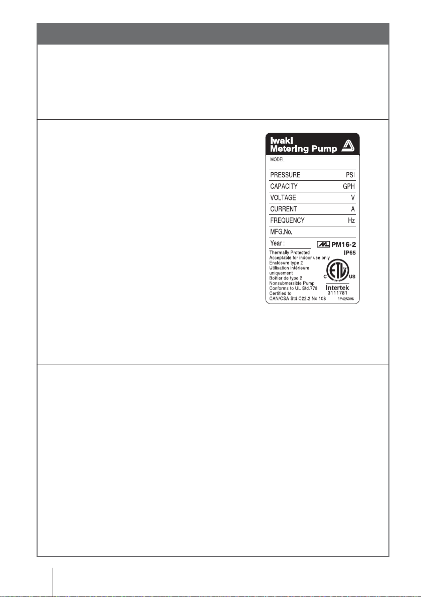
Check the nameplate to see if the
information such as model codes, discharge capacity, discharge pressure
and power voltage are as ordered.
b. Check if the delivery is damaged or deformed.
Check for transit damage and loose bolts.
2
Order confirmation
Page 3

Contents
Order confirmation .............................................................................................2
Safety instructions .......................................................................6
Warning ............................................................................................................. 7
Caution .............................................................................................................. 9
Precautions for use ........................................................................................13
Overview ......................................................................................17
Introduction .....................................................................................................17
Pump structure & Operating principle .........................................................17
Features .......................................................................................................19
Operational functions...................................................................................19
Part names...................................................................................................... 24
Pump............................................................................................................24
Operational panel ....................................................................................... 25
Basic displays & Pump states ...............................................................26
Identification codes ....................................................................................... 28
Pump/Drive units ........................................................................................ 28
Installation ..................................................................................30
Pump mounting .............................................................................................. 30
Pipework ..........................................................................................................31
Tube connection ..........................................................................................31
Check valve mounting ................................................................................ 33
Wiring .............................................................................................................. 35
Power voltage/Earthing ..............................................................................35
Signal wire connection.................................................................................37
Connections .......................................................................................... 39
Contents
3
Page 4

Operation .....................................................................................42
Before operation ............................................................................................ 42
Points to be checked ...................................................................................42
Retightening of pump head fixing bolts .......................................................42
Use of hexagon wrench instead of a torque wrench ............................. 43
Degassing ................................................................................................... 43
Flow rate adjustment .................................................................................. 46
Stroke rate adjustment ...........................................................................47
Stroke length adjustment....................................................................... 49
Before a long period of stoppage (One month or more) ............................. 50
Operation programming ................................................................................51
Programming flow ........................................................................................52
Manual operation ........................................................................................54
EXT operation ............................................................................................. 55
EXT mode ............................................................................................. 55
EXT mode programming ....................................................................... 56
User mode .................................................................................................. 65
STOP/Pre-STOP function ..................................................................... 66
STOP/Pre-STOP function cancellation .................................................68
OUTPUT function ...................................................................................70
ANA-V/-R selection ................................................................................72
Buffer ON/OFF selection ........................................................................74
PIN number entry ...................................................................................76
Keypad lock .................................................................................................78
Keypad lock activation ............................................................................79
Keypad lock release ...............................................................................79
Calibration mode ........................................................................................ 80
Unit change ..................................................................................................81
spm indication ..............................................................................................81
4
Contents
Page 5

Maintenance ................................................................................82
Troubleshooting ............................................................................................. 83
Inspection ....................................................................................................... 85
Daily inspection .......................................................................................... 85
Periodic inspection .....................................................................................85
Wear part replacement .................................................................................. 86
Wear part list ...............................................................................................86
Before replacement .....................................................................................87
Valve set replacement .................................................................................87
Discharge valve set dismantlement/assembly .......................................87
Suction valve set dismantlement/assembly .......................................... 89
Spacer set replacement (Auto degassing type) .................................... 90
Air vent valve set replacement (Auto degassing type) ...........................91
Diaphragm replacement ..............................................................................91
Exploded view ................................................................................................ 94
Pump head, Drive unit & Control unit .........................................................94
Pump head ................................................................................................. 95
EWN-[B09•B11•B16•B21•C16•C21] [VC•VH•VE•PC•PH•PE•TC] .........95
EWN-[B31•C31•C36] [VC•VH•VE•PC•PH•PE•TC] ...............................96
EWN FC .................................................................................................97
EWN-C31 P6-V .....................................................................................98
EWN SH/SH-H/SH-H2 ..........................................................................99
EWN with an Automatic air vent ..........................................................100
Specifications/ Outer dimensions ..............................................................101
Specifications ............................................................................................101
Pump unit .............................................................................................101
Power cable ..........................................................................................103
Pump colour .........................................................................................103
Outer dimensions...................................................................................... 104
Contents
5
Page 6
Safety instructions
t
Read through this section before use. This section describes
important information for you to prevent personal injury or
property damage.
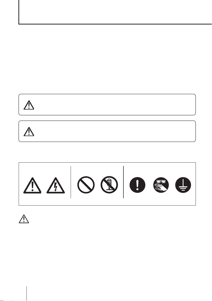
■ Symbols
In this instruction manual, the degree of risk caused by incorrect use is noted
with the following symbols. Please pay attention to the information associated
with the symbols.
WARNING
CAUTION
Indicates mishandling could lead to a fatal or
serious accident.
Indicates mishandling could lead to personal
injury or property damage.
A symbol accompanies each precaution, suggesting the use of "Caution", "Prohibited actions" or specific "Requirements".
Caution marks Prohibited mark Requirement mark
Caution
Electrical
shock
Prohibited
Do not rework
or alter
Requiremen
Wear
protection
Grounding
Export restrictions
Technical information contained in this instruction manual might be treated
as controlled technology in your countries, due to agreements in international
regime for export control.
Please be reminded that export license/permission could be required when this
manual is provided, due to export control regulations of your country.
6
Safety instructions
Page 7
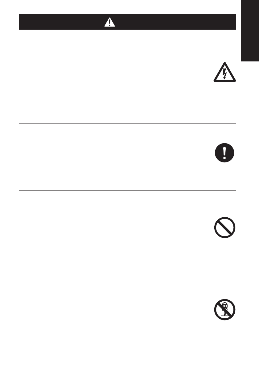
WARNING
Turn off power before service
Risk of electrical shock. Be sure to turn off power to stop the pump
and related devices before service is performed.
Couper l’alimentation électrique de la pompe avant intervention
Intervenir sur la pompe sans avoir au préalablement coupé
l’alimentation électrique peut déclencher des décharges électriques. Avant d’entreprendre n’importe quel type d’intervention,
veillez à mettre la pompe et tout dispositif connexe hors tension à
l’aide de l’interrupteur prévu à cet effet.
Stop operation
If you notice any abnormal or dangerous conditions, suspend operation immediately and inspect/solve problems.
Electrical
shock
Safety instru ctions
Arrêter le fonctionnement
Si vous détectez une anomalie ou des signes suspects et inhabituels pendant le fonctionnement, interrompez immédiatement les
opérations et inspectez, résolvez les problèmes.
Do not use the pump in any condition other than its intended purpose
The use of the pump in any conditions other than those clearly
specified may result in failure or injury. Use this product in specified
conditions only.
Se conformer uniquement aux applications prévues
La pompe doit être utilisée conformément à l’usage pour lequel elle
a été prévue et dans le respect de ses caractéristiques techniques.
Toute utilisation non conforme peut entraîner un incident ou endommager le dispositif.
Do not modify the pump
Alterations to the pump carries a high degree of risk. It is not the
manufacturer's responsibility for any failure or injury resulting from
alterations to the pump.
Ne pas modifier la pompe
Ne jamais modifier une pompe sous peine de causer un incident
grave. Iwaki ne pourra en aucun cas être tenu responsable d’un incident ou de dégâts survenus à la suite d’une modification du dispositif.
Requirement
Prohibited
Do not rework
or alter
WARNING
7
Page 8
Wear protective clothing
Always wear protective clothing such as an eye protection, chemical
resistant gloves, a mask and a face shield during disassembly , assembly or maintenance work. The specific solution will dictate the degree
of protection. Refer to MSDS precautions from the solution supplier.
Porter un équipement de protection
T oujours porter un équipement de prot ection (lunettes, gants résistants aux produits chimiques, masque, casque) durant le démontage,
l’assemblage et la maint enance.
Le travail effectué dictera le degré de protection. Référez-vous au
MSDS de la solution proposée par le fournisseur.
Do not damage the power cable
Do not pull, knot, or crush the power cable. Damage to the power
cable could lead to a fire or electrical shock if cut or broken.
Ne pas endommager le câble électrique
Ne pas tirer ou faire un nœud avec le câble électrique. Endommager un câble électrique pout provoquer une incendie ou une
décharge électrique.
Wear
protection
Prohibited
Do not operate the pump in a flammable atmosphere
Do not place explosive or flammable material near the pump.
Ne pas utiliser la pompe dans une atmosphère explosive
Pour votre sécurité, du matériel dangereux ou inflammable ne doit
pas être placé près de la pompe.
Risk of electric shock
This pump is supplied with a grounding conductor and groundingtype attachment plug. To reduce the risk of electric shock, be
certain that it is connected only to a properly grounded, grounding
type receptacle.
Risque de choc électrique
La pompe est fournie avec un conducteur pour mise à la terre et
une prise courant. Afin de réduire le risque de choc électrique, veillez à ce que la terre soit correctement raccordée.
8
WARNING
Prohibited
Prohibited
Page 9

CAUTION
Qualified personnel only
The pump should be handled or operated by qualified personnel with a
full understanding of the pump. Any person not familiar with the product should not take part in the operation or maintenance of the pump.
Opérateur qualifié uniquement
La pompe doit être manipulée ou utilisée par du personnel qualifié
connaissant parfaitement la pompe. Tout autre personne étrangère ne
doit pas prendre part à l’utilisation ou à la maintenance de la pompe.
Use specified power only
Do not apply power other than that specified on the nameplate. Otherwise, failure or fire may result. Ensure the pump is properly grounded.
Utilisez une tension appropriée uniquement
Ne pas appliquer une autre tension que celle spécifiée sur la
plaque signalétique sinon, il peut en résulter une panne ou une incendie. Assurez-vous également de la mise à la terre de la pompe.
Safety instru ctions
Requirement
Prohibited
Do not run pump dry
Do not run pump dry for more than 30 minutes (even when the
pump runs for degassing). Otherwise, the pump head fixing screws
may loosen and liquid may leak. Optimise your system. If the pump
runs dry for a long period (for more than 30 minutes), the pump
head and the valve cases may deform by friction heat and consequently leakage results.
Ne faite pas fonctionner la pompe à sec
Ne faite pas fonctionner la pompe à sec plus de 30 minutes (même
lorsque la pompe fonctionne pour dégazer). Sinon, les visses de
fixation de la tête peuvent se dévisser et il peut y avoir une fuite
de liquide. Optimalisez l’installation de façon à ce que la pompe
ne fonctionne pas à sec. Si la pompe fonctionne à sec pour une
longue période (plus de 30 minutes), la tête de la pompe et le guide
de clapets peuvent être déformés par friction causée par la chaleur
et il en résulterait des fuites.
CAUTION
Caution
9
Page 10
Keep electric parts and wiring dry
Risk of fire or electric shock. Install the pump where it can be kept dry.
Ne mouillez pas les parties électriques ou les câbles
Risque d’incendie ou de décharge électrique. Installez la pompe
dans un endroit sec.
Observe an applicable MSDS
Take account of installation environment. Chemicals should be
controlled in accordance with a MSDS. Do not send potable water
or circulate heated water with this pump.
Prohibited
Observez un « MSDS » applicable
Tenez compte de l’environnement. Les produits chimiques doivent être surveillés en accord avec un MSDS. Ne pas utilisez cette
pompe avec de l'eau potable ou de l'eau chaude.
Do not install or store the pump:
• In a flammable atmosphere.
• In a dusty/humid environment.
• Where ambient temperature can exceed 0-40ºC.
• In direct sunlight or wind & rain.
N’installez ou ne stock ez pas la pom pe dans les en droits suiv antes :
• Dans une atmosphère inflammable
• Dans un endroit poussiéreux ou humide.
• Dans une place où la température n’est pas comprise entre 0 et 40 °C.
• Directement sous le soleil, le vent ou la pluie.
Spill precautions
Ensure protection and containment of solution in the event of
plumbing or pump damage (secondary containment).
Caution
Prohibited
Déversement accidentel
Prenez des mesures protectrices contre tout incident résultant d’un
débit trop important de la pompe ou d’une casse de tuyauterie.
10
CAUTION
Requirement
Page 11
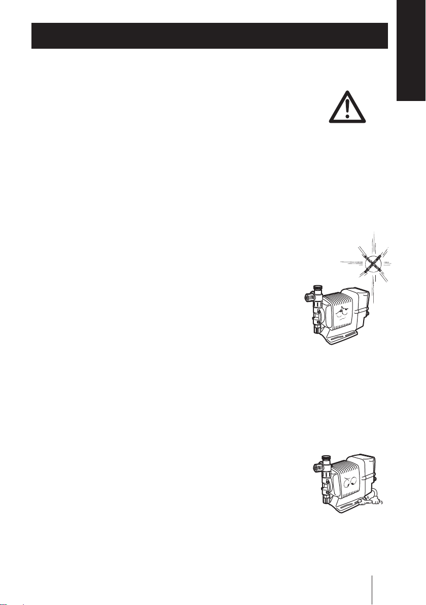
Do not use the pump in a wet location
The pump is not waterproof. Use of the pump in wet or extremely
humid locations could lead to electric shock or short circuit.
Safety instru ctions
N’utilisez pas la pompe sous l’eau
La pompe n’est pas complètement étanche. Utiliser la pompe dans
l’eau ou dans un endroit très humide peut créer une décharge électrique ou un court-circuit.
Grounding
Risk of electrical shock! Always properly ground the pump. Conform to local electric codes.
Mise à la terre
Veillez à ne pas faire fonctionner la pompe sans avoir au préalable
prévu une mise à la terre. Celle-ci permettra d’éviter d’éventuelles
décharges électriques. Vérifiez que le câble de mise à la terre est
bien branché.
Install a GFCI (earth leakage breaker)
An electrical failure of the pump may adversely affect other devices on the same line. Purchase and install a GFCI (earth leakage
breaker) separately.
Détecteur de fuites à la terre
Un problème électrique peut affecter défavorablement le dispositif.
Achetez et installez un détecteur de fuites à la terre.
Prohibited
Grounding
Electrical
shock
Preventative maintenance
Follow instructions in this manual for replacement of wear parts. Do
not disassemble the pump beyond the extent of the instructions.
Remplacement des pièces usées
Suivez les instructions de ce manuel pour remplacer les pièces
usées. Ne démontez pas la pompe au-delà des instructions.
Do not use a damaged pump
Use of a damaged pump could lead to an electric shock or death.
N’utilisez pas une pompe endommagée
Utiliser une pompe endommagée peut provoquer une décharge
électrique ou la mort.
CAUTION
Requirement
Prohibited
11
Page 12
Disposal of a used pump
Dispose of any used or damaged pump in accordance with local
rules and regulations. If necessary, consult a licensed industrial
waste disposal company.
Elimination des pompes usées
Elle doit se faire en conformité avec les règles locales en vigueur
(consultez une entreprise certifiée et spécialisée).
Check pump head bolts
Liquid may leak if any of the pump head bolts become loose.
Tighten the bolts evenly to the following torque in diagonal order
before initial operation and at regular intervals.
Tightening torque
EWN-B11/-B16/-B21/-C16/-C21 : 19 lb-in
EWN-B31/-C31/-C36 : 22.6 lb-in
Serrez la tête de pompe
La pompe peut fuiter si les boulons sont desserrés. Resserrez les
boulons diagonalement et uniformément avant la première utilisation Resserrez les boulons régulièrement pour éviter tout fuite.
Couple de serrage
EWN-B11/-B16/-B21/-C16/-C21 : 19 lb-in
EWN-B31/-C31/-C36 : 22.6 lb-in
Solution compatibility
This pump has been evaluated for use with water only. The suitability of this pump for use with liquids other than water, such as acid
and alkaline, is the responsibility of the user. For liquids other than
water, select the best-suited liquid end material combination using a
chemical compatibility chart.
Requirement
Caution
Compatibilité avec la solution
Cette pompe a été évaluée pour l’utilisation avec l’eau uniquement.
L’aptitude de cette pompe à être utilisée avec d’autres produits, tels
que les acides et les alcalins, est de la responsabilité de l’utilisateur.
Pour des liquides autres que l’eau, choisissez le matériel le plus
compatible selon la résistance chimique.
12
CAUTION
Caution
Page 13
Precautions for use
• Electrical work should be performed by a qualified electrician. Otherwise, personal injury or property damage could
result.
Safety instru ctions
Le raccordement électrique de la pompe doit être effectué
par du personnel qualifié sinon, il pourrait y avoir un dommage corporel ou incorporel.
• Do not install the pump:
–In a flammable atmosphere.
–In a dusty/humid place.
–In direct sunlight or wind & rain.
– Where ambient temperature can exceed 0-40ºC.
Protect the pump with a cover when installing it out of
doors.
Ne pas installer la pompe dans les endroits suivants:
–Dans une atmosphère inflammable
–Dans une atmosphère poussiéreuse ou humide.
– Sous les rayonnements du soleil, dans le vent ou sous la pluie.
– La température ambiante doit être comprise entre 0 et 40°C.
Protégez la pompe par un capot si vous l’installez dehors.
Caution
• Select a level location, free from vibration, that won't hold
liquid. Anchor the pump with four M5 bolts so it doesn't
vibrate. If the pump is not installed level, output may be
affected.
Choisissez un endroit où il n’y a pas de vibrations et où le
liquide peut s’évacuer. Fixez la pompe à l’aide de visses
M5 de façon à ne pas avoir de vibrations. Si la pompe est
inclinée, le débit peut être réduit.
Precautions for use
13
Page 14
• When two or more pumps are installed together, vibration
may be significant, resulting in poor performance or failure.
Select a solid foundation (concrete) and fasten anchor bolts
securely to prevent vibration during operation.
Si plusieurs pompes sont installées ensemble, elles interagissent et les vibrations peuvent devenir importantes, ce
qui engendre des performances médiocres ou des ratures.
Choisissez un endroit solide et fixez les boulons correctement pour évitez les vibrations pendant le fonctionnement.
• A llow sufficient spac e around the pump for easy access
and maintenance.
Prévoyez de l’espace autour de la pompe pour faciliter
l'accès et la maintenance.
• Install the pump as close to the supply tank as possible.
Installez la pompe le plus près possible du tank de produit.
• When handling liquids that generate gas bubbles (sodium
hypochlorite or hydrazine solution), install the pump in a
cool and dark place. Flooded suction installation is strongly
recommended.
Caution
Caution
Caution
Installez la pompe dans une place froide à l’abri du soleil
lorsqu’il s’agit du dosage de produits dégazant tels que
l’hypochlorite de sodium ou l’hydrazine. Mettre la pompe en
charge est vivement recommandé.
14
Precautions for use
Caution
Page 15

• Use care handling the pump. Do not drop. An impact may
affect pump performance. Do not use a pump that has
been damaged to avoid the risk of electrical damage or
shock.
Veillez à ne pas laisser tomber la pompe sur le sol. Un
impact important pourrait réduire les performances de la
pompe. Ne pas utiliser une pompe endommagée sinon il
pourrait y avoir un courant de fuite ou une décharge électrique.
• The pump has a rating of IP65, but is not waterproof. Do
not operate the pump while wet with solution or water.
Failure or injury may result. Immediately dry off the pump if
it gets wet.
Safety instru ctions
Le pompe est IP65 mais n’est pas complètement étanche.
Ne pas laisser la pompe couverte de liquide pompé ou
sous la pluie. Il pourrait y avoir des ratés ou préjudices. Si
la pompe a été mouillée, sechez-la directement.
• Do not close discharge line during operation. Solution may
leak or piping may break. Install a relief valve to ensure
safety and prevent damaged plumbing.
Ne fermez pas la ligne de refoulement lorsque la pompe est
en fonctionnement sinon il pourrait y avoir des fuites de liquide ou la tuyauterie pourrait céder. Installez une soupape
de sécurité pour des raisons de sécurité et pour éviter tout
dommage de la tuyauterie.
• Do not remove the control unit. Note that an applicable control unit differs with each drive unit. Do not attach a control
unit to a different drive unit. Otherwise, an electrical circuit
or the drive unit may fail.
N’enlevez pas l’unité de contrôle. Chaque partie électromagnétique a son propre unité de contrôle. Ne mettez pas
autre unité de contrôle au module de puissance sinon il
pourrait y avoir un court circuit ou un disfonctionnement de
la partie électromagnétique.
Caution
Caution
Caution
Precautions for use
15
Page 16
• Solution in the discharge line may be under pressure.
Release the pressure from the discharge line before disconnecting plumbing or disassembly of the pump to avoid
solution spray.
Le liquide au refoulement peut être sous pression.
Relâchez la pression du refoulement avant de démonter la
pompe ou d’enlevez le tubage pour éviter tout jet de liquide.
• Wear protective clothing when handling or working with
pumps. Consult solution MSDS for appropriate precautions.
Do not come into contact with residual solution.
Portez un équipement de sécurité lorsque vous manipulez
la pompe. Consultez le MSDS pour utilisez les précautions
appropriées .Evitez tout contact avec le liquide chimique.
• Do not clean the pump or nameplate with a solvent such
as benzine or thinner. This may discolour the pump or
erase printing. Use a dry or damp cloth or a neutral
detergent.
Ne nettoyez pas la pompe ou la plaque signalétique à
l’aide d’un solvant comme le benzène ou le white spirit.
Cela pourrait décolorer la pompe ou effacer l’impression.
Utilisez un tissu sec ou mouillé avec de l’eau ou un détergent neutre.
Requirement
Caution
Thinner
Benzine
• This pump has been eveluated for use wit h water only.
Cette pompe a été testée uniquement avec de l'eau.
16
Precautions for use
Caution
Page 17
Overview
Pump characteristics, features and part names are described
in this section.
Introduction
Pump structure & Operating principle
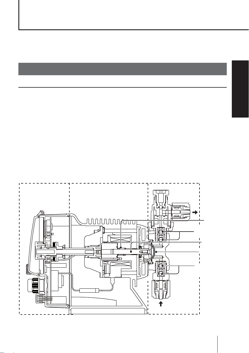
The EWN series is a diaphragm metering pump which consists of a pump
head, drive unit and control unit. A diaphragm is directly driven by electromagnetic force.
Principle of operation
The electromagnetic force and spring force make reciprocating motion. The
reciprocating motion is transferred to a diaphragm through a plunger and then
volumetric change occurs in the pump head. This action transfers liquid along
with pump head valve action.
Control unit Pump headDrive unit
OUT
Spring
Pump head valve
(Discharge side)
Plunger
Diaphragm
Overview
IN
Pump head valve
(Suction side)
Introduction
17
Page 18

● Auto degassing system
Discharge port Air vent port
AIR
OUT
Automatic air
vent valve body
LOCK
Pump head valve
Air vent valve
Pump head
Suction port
• Once air is entrained through the suction port, the working pressure difference
between the pump head valve and the air vent valve separates entrained air
from liquid.
• Entrained air is expelled to ope n air through the automatic air vent valve body.
• Only liquid is delivered to a discharge line through the discharge port. Note a
small amount of liquid is expelled with entrained air.
18
Introduction
Page 19
Features
● Multivoltage operation
The EWN-R series is a multivoltage type (100-240VAC) and can be selected
without concern for local power voltage.
● High turndown ratio
Digitally-controlled stroke rate range is 0.1-100%. The stroke length shifts for
a fine flow adjustment.
● Waterproof and dustproof structure (IP65)
With the aim of improving resistance to exposure to liquid, the control unit is
installed on the back of the pump and the control panel is protected with a
cover as standard equipment. A rubber gasket is provided between the pump
head and the bracket to prevent water from entering from the periphery of
the pump head.
* This pump is not completely water resistant. Protect the pump with a cover when
installing it out of doors.
Operational functions
Overview
● Manual operation (see page 54)
The start/stop of the pump by key operation
Key operation
(Push key)
Run Run
Pump operation
Stop
*Manual operation can be done at any time during operation or stop.
Stop
● EXT operation (see page 55)
The pump operation by the external signal.
The external operation is available after multiplier or divisor programming.
Introduction
19
Page 20
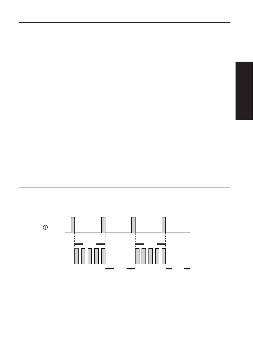
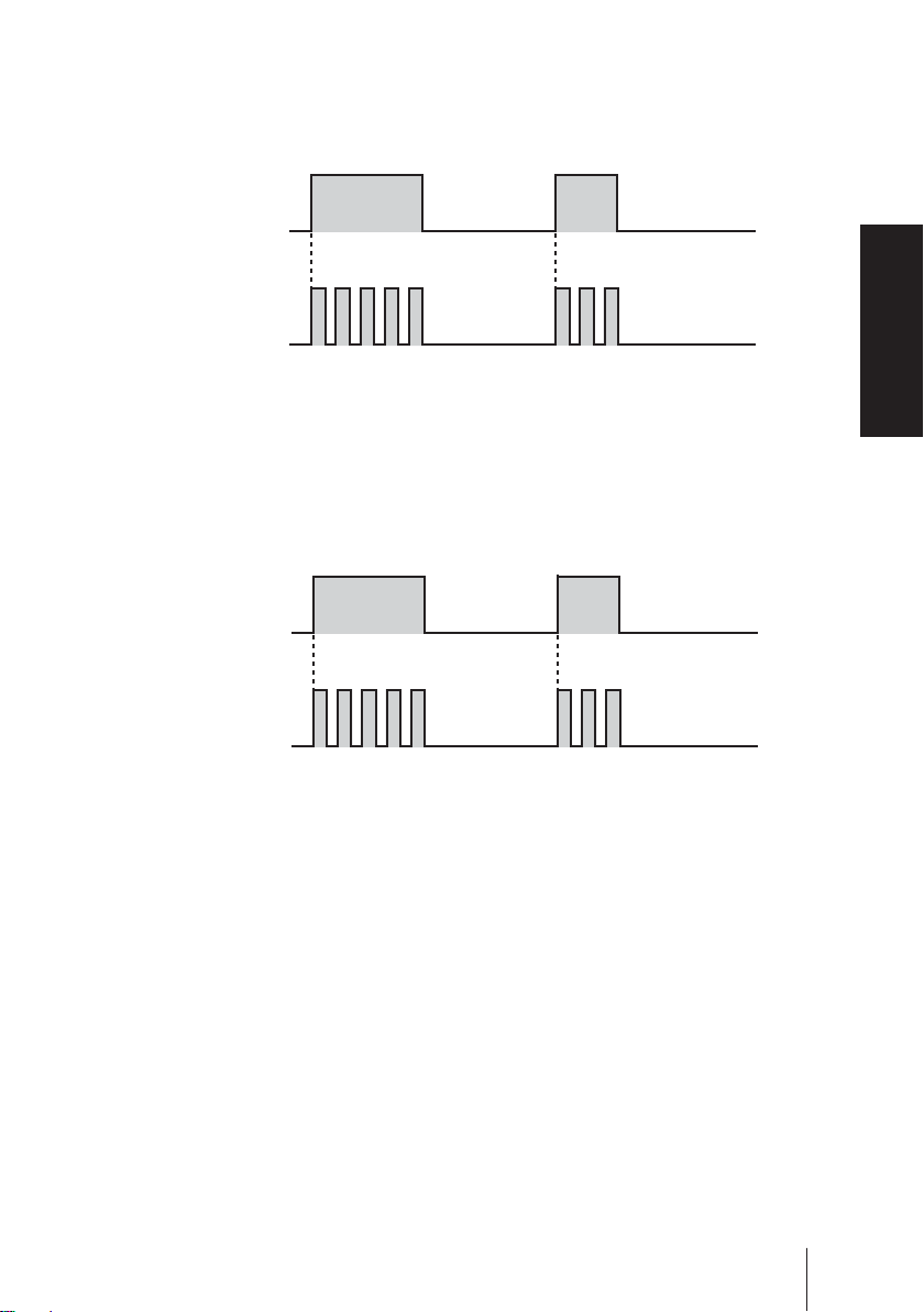
Multiplier programming (See page 57)
1-9999 shots can be programmed to one pulse signal.
*In the EXT operation, the pump runs at the manual operation stroke rate.
*The pump makes one shot per pulse when the multiplier is programmed to 1.
Example) When the multiplier is programmed to 5, the pump makes five
shots per signal.
Pulse signal input
Pump operation
1 2 3 4 5 1 2 3 4 5
A buffer works when the pump receives an external signal before the programmed shots per signal is completed.
Pulse signal input
Pump operation
1 2 3 4 5 1 2 3 4 5 1 2 3 4 5 1 2 3
*The buffer stores the external signals for up to 65535 shots.
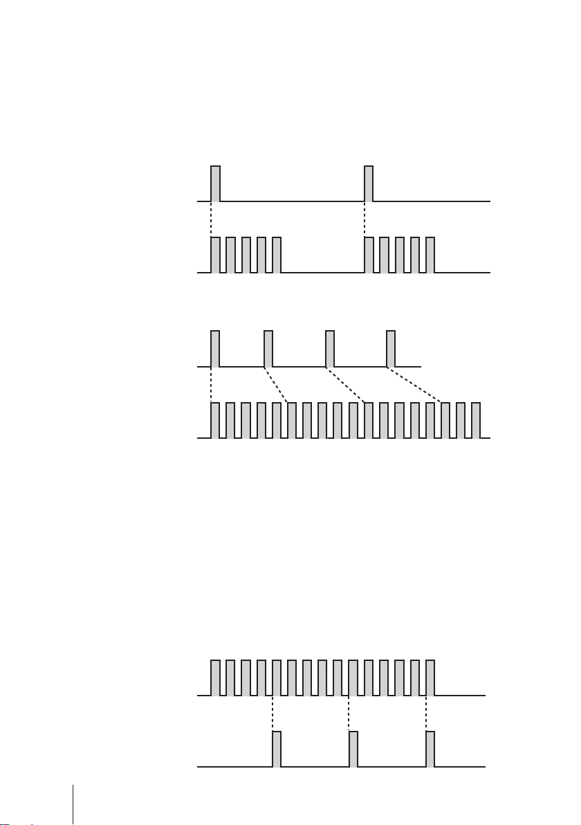
Divisor programming (See page 59)
1-9999 pulse signals can be programmed to make one shot.
* The pump can not run over a programmed stroke rate (max. 100%) even if a divisor
is set to run the pump faster.
*The pump makes one shot per pulse when a divisor is programmed to 1.
Example) When a divisor is programmed to 5, the pump makes one shot per
5-signal.
Pulse signal input
1 2 3 4 5 1 2 3 4 5 1 2 3 4 5
Pump operation
20
Introduction
Page 21
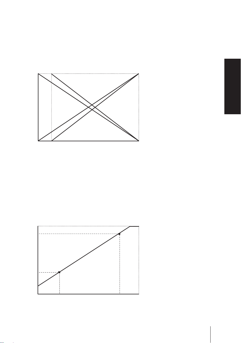
ANA. R (analogue rigid) programming (See page 63)
The pump increases/decreases a flow rate in proportion to 0-20mA. Four (420, 20-4, 0-20, 20-0) programs are provided.
In "4-20" or "20-4" program a disconnection sensor works to stop the pump
as a current value falls below 4mA ("DISCN" blinks on the screen). Check
wiring as necessary. Pushing the start/stop key, this state is released.
100%
b
d
c
a
Condition
The left graph is in the following
programs.
a. 4-20 (Default setting)
b. 20-4
c. 0-20
d. 20-0
Overview
04
20mA
ANA. V (analogue variable) programming (See page 61)
The pump increases/decreases a flow rate in proportion to 0-20mA.
Setting two points can draw a straight line. Depending on the position of the
two points, 0 % may not come at 0mA in some cases. When a stroke rate
could become over 100% at some mA due to the setting, pump speed is limited to 100%.
100%
85
30
06
P1
P2
17
Condition
The left graph is in the following
setting.
P1 = 6 mA, 30%
P2 = 17 mA, 85%
20mA
Introduction
21
Page 22
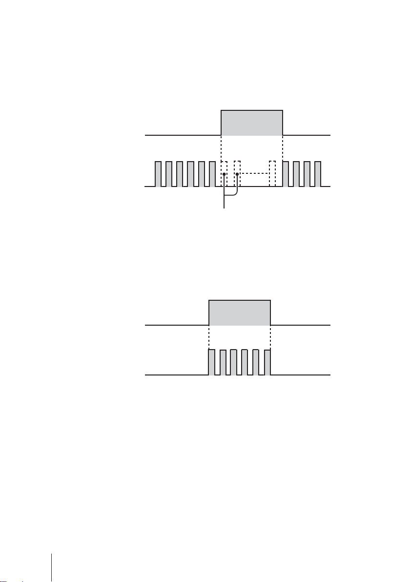
● STOP function (See page 66)
The start/stop of the pump can be controlled by the external signal.
When "NOR. OP" is selected...
The pump stops while receiving the external signal via the STOP terminal.
*The pump resumes operation when the STOP signal is released.
STOP signal input
Run Run
Pump operation
Stop
The pump stops running while
the STOP signal is inputted.
When "NOR. CL" is selected...
The pump runs while receiving the external signal via the STOP terminal.
*The pump stops operation when the stop signal is released.
STOP signal input
Run
Pump operation
Stop Stop
● Pre-STOP function (See page 66)
When "NOR. OP" is selected...
The STOP LED lights orange while the pump receiving the external signal via
the Pre-STOP terminal (a contact is closed). Note the pump does not stop
running.
When "NOR. CL" is selected...
The STOP LED stops lightening while the pump receiving the external signal
via the Pre-STOP terminal (a contact is closed).
22
Introduction
Page 23
● AUX function (See page 43)
The pump runs at the maximum stroke rate while receiving the external signal via the AUX terminal. Use this function for degassing.
Pulse signal input
Pump operation
1 2 3 4 5 1 2 3
● Priming function (See page 43)
The pump runs at the maximum stroke rate while both the UP and DOWN
keys are pressed. Use this function for degassing.
Press Press
▲+▼ keys
Overview
Pump operation
1 2 3 4 5 1 2 3
● OUTPUT function (See page 70)
Signals can be sent via the output terminal in sync with manual operation.
The terminal can be set to on or off.
Introduction
23
Page 24
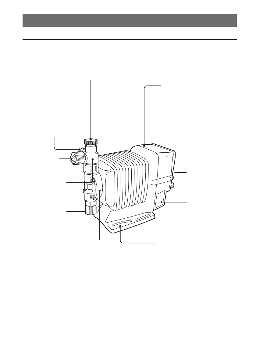
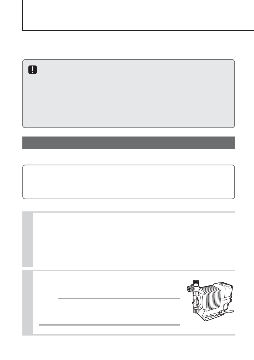
Part names
Pump
Adjusting screw
Used for opening the air vent port.
Air vent port
Always connect a tube.
Be sure to return the tube
end to a supply tank or a
container.
The air vent port can
rotate 90 degrees.
Outlet
Air vent body
Control unit
Used for the start/stop of the
pump and stroke rate adjustment/programming.
Stroke length
adjusting knob
Used for adjusting
a flow rate.
24
Part names
Inlet
Pump head
Nameplate
Describes the
pump specifications.
Base
Always fix with bolts.
Page 25
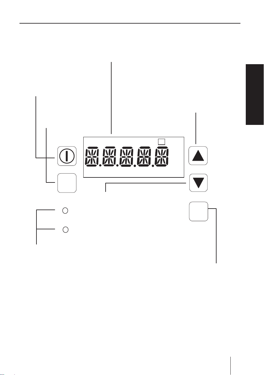
Operational panel
Display
An operational status, a selected mode and
a programmed value are shown here.
START/STOP key
Used for starting/stopping
the pump operation.
EXT key
Used for entering the
EXT mode.
MAN DIV MULT ANA. RV P
OVER P1 2 LOCK Err Disp SET
EXT
DOWN key
Used for decreasing numeric
values or selecting a program-
ON
STOP
LED
Lights as the pump is turned
on and blinks at each shot.
ming mode.
UP key
Used for increasing numeric values or selecting a programming
mode.
!
spm
L/h
mA
DISP
DISP key
Used for checking flow information or changing units.
Overview
Part names
25
Page 26
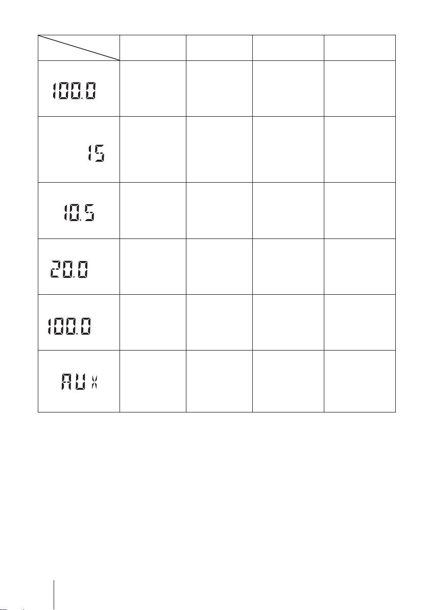
■
Basic displays & Pump states
STOP LED
lights red
MAN
%
MULT
DIV
――
ANA. R
%
%
ANA. V
%
―
――
――
――
―― ―
ON LED lights
orange
Manual wait
state. Display
shows stroke
rate in %.
ON LED lights
EXT(Multiply)
mode. The
pump is waiting
for the external
signal.
EXT(Divide)
mode. The
pump is waiting
for the external
signal.
EXT(ANA.
R) mode. The
pump is waiting.
EXT(ANA.
V) mode. The
pump is waiting.
green
―
ON LED blinks
green
The pump
is running in
manual mode.
Display shows
stroke rate in %.
EXT(Multiply)
mode. The
pump is making
the displayed
# of shots per
signal.
EXT(Divide)
mode. The
pump is running
at the displayed
stroke rate.
EXT(ANA.
R) mode. The
pump is running
at the displayed
stroke rate.
EXT(ANA.
V) mode. The
pump is running
at the displayed
stroke rate.
AUX mode.
The pump
is running at
the maximum
stroke rate.
26
Part names
Page 27
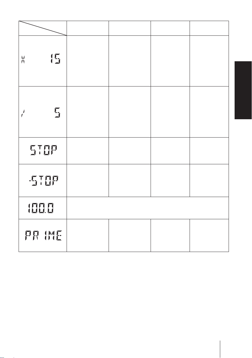
STOP LED
lights red
ON LED lights
orange
ON LED lights
green
ON LED blinks
green
EXT(Multiply)
MULT
―
SET
programming
mode. The
pump is set
to make the
displayed #
of shots per
――
Overview
signal.
EXT(Divide)
programming
DIV
―
SET
mode. The
pump is set
to make one
shot for the
――
displayed # of
signals.
Operation stop
by the STOP
signal. ON LED
―――
lights green.
STOP signal
input in the
manual wait
―――
state. ON LED
lights orange.
MAN
LOCK
Keypads are locked. Keypad operation is ineffective in this state.
Release keypad lock before operation.
%
PRIME mode.
The pump
―――
is running at
the maximum
stroke rate.
Part names
27
Page 28
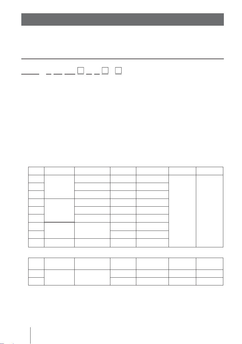
Identification codes
The model codes of the pump/drive units and the control unit represent the following information.
Pump/Drive units
EWN - B 11 VC
U R -
a b c d e f g h i
a. Series name
EWN: Multivoltage electromagnetic metering pump
b. Drive unit (Average power consumption)
B: 20W
C: 24W
c. Diaphragm effective diameter
09: 8mm 11: 10mm 16: 15mm
21: 20mm 31: 30mm 36: 35mm
d. Wet end materials
Code Pump head Valve O ring Valve seat Gasket Diaphragm
VC
VH HC276 EPDM EPDM
VE CE EPDM EPDM
PC
PH HC276 EPDM EPDM
PE CE EPDM EPDM
FC
TC FKM FKM
SH SUS316 HC276 SUS316
PVC
GFRPP
PVDF CE
CE FKM FKM
CE FKM FKM
PCTFE
―
―
PTFE
PTFE
+ EPDM
Automatic air vent (Auto degassing type)
Air vent valve
Code
VC
VH HC276 HC276 EPDM EPDM
guide A
PVC PVC
Material code
PVC : Transparent polyvinyl chloride GFRPP :
PVDF : Polyvinylidene difluoride EPDM : Ethylene-propylene rubber
FKM : Fluorine-contained rubber PTFE : Polytetrafluoroethylene
HC276 : HASTELLOY C276 SUS316 : Austenite stainless steel
CE : Alumina ceramics PCTFE : Polymonochlorotrifluoroethyle
28
Identification codes
Air vent valve
guide B
Valve Separate pin Valve seat O ring
CE Titanium FKM FKM
Glassfiber -reinforced polypropylene
Page 29

e. Tube connection bore
No. Hose size (ID×OD) Wet end materials Pump models
ø1/4"×ø3/8"
ø3/8"×ø1/2"
No
code*
1ø4×ø9
2ø4×ø6
3ø6×ø8
4 ø8×ø13 VC/VH/VE/PC/PH /PE EWN-31 & -36
5 ø9×ø12 VC/VH/VE/PC/PH/PE EWN-31 & -36
6 ø10×ø12 VC/VH/VE/PC/PH/PE EWN-31 & -36
23 ø6×ø12 VC/VC-C EWN-09/-11/-16 & -21
24 ø5×ø8 VC/TC/VC-C EWN-09/-11/-16 & -21
1/10
2/10
3/10
* ø4×ø6 and ø6×ø12 are equipped to the EWN-09/-11/-16/-21 (VC-C type).
1/4-18NPT FC/SH/SH-H /SH -H2
IN/AIR: 1/4"×ø3/8"
OUT: 1/4-18NPT
IN: ø15×ø22
OUT: ø3/8"×ø1/2"
IN: ø4×ø9
OUT: 1/4-18NPT
IN: ø4×ø6
OUT: 1/4-18NPT
IN: ø6×ø8
OUT: 1/4-18NPT
VC/VH/VE/PC/PH/PE/TC/VC/
VH/VE-C/VC-A/VH-A
VC/VH/VE/PC/PH/PE/TC
PC/PE-H/PE-H2 EWN-11 & -16
P6-V EWN-31
VC/VH/VE/PC/PH/PE/VC/
VH/VE-C
VC/VH/VE/PC/PH/PE/TC/VC/
VH/VE-C/VC-A/VH-A
VC/VH/VE/PC/PH/PE/TC/VC/
VH/VE-C/VC-A/VH-A
/VC-A/VH-A
PC/PH/PE-H EWN-11 & -16
PC/PH/PE-H EWN-11 & -16
PC/PH/PE-H EWN-11 & -16
EWN-09/-11/-16 & -21
EWN-31 & -36
EWN-11/-1 6/-2 1/-31 & -36
EWN-09/-11/-16 & -21
EWN-09/-11/-16 & -21
EWN-09/-11/-16 & -21
Overview
f. Power cable
U: American 115VAC type
U2: American 230 VAC type
g. Control unit function
R: Standard
h. Special version
C: High compression type
H: High pressure type
V: High viscosity type
A: Auto degassing type
i. Special configuration
H2: High pressure type (2MPa)
Identification codes
29
Page 30
Installation
This section describes the installation of the pump, tubing and
wiring. Read through this section before work.
Observe the following points when installing the pump.
• Be sure to turn off power to stop the pump and related devices before work.
• Upon sensing abnormality or danger, stop work immediately. Remove
problems before resuming work.
• Do not place dangerous or flammable goods near the pump for your safety.
• Risk of an electrical leak or shock. Do not use a damaged pump.
Pump mounting
Select an installation location and mount the pump.
Necessary tools
• Four M5 bolts (pump mounting)
• Adjustable wrench or spanner
Select a suitable place.
1
Always select a flat floor free of vibration. See the "Precautions for use"
section for detail.
Flooded suction is recommended when handling a gaseous liquid such
as sodium hypochlorite.
Anchor the pump by the M5 bolts.
2
Be sure to fix the pump at four points.
NOTE
Install the pump horizontally. If the pump is installed at a
tilt, a flow may reduce.
30
Pump mounting
Page 31

Pipework
Connect tubes to the pump and install a check valve.
Before operation
• Cut the tube ends flat.
Necessary tools
• Adjustable wrench or spanner
Tube connection
a. Pass a tube into the fitting nut and
hose stopper and then slide it down to
the hose adapter as far as it will go.
b. Fit the tube end (hose adapter) to the
fitting. Then hand tighten the fitting nut.
c. Retighten the fitting nut by turning it
180 degrees with an adjustable wrench
or spanner.
* The plastic fitting nut may be broken if it is
tightened too much.
Tube end (Side view)
Installation
Tube
Fitting nut
Hose
stopper
Slide it
down
Hose
adapter
Fitting
Connect tubes into the inlet and
1
outlet.
Tube
Tube
Outlet
Inlet
Pipework
31
Page 32

Connect an air bleed tube into the
2
air vent port.
Route back the other tube end to a
supply tank or a container.
For the auto degassing type, connect another air bleed tube into the
automatic air vent valve body as
well.
Decide an air vent port direction.
3
The air vent port can rotate 90 degrees.
a. Turn the lock nut anticlockwise.
b. Adjust the direction of the air vent
port.
c. Hand-tighten the lock nut, holding
the air vent body A.
d. Turn the lock nut 90 degrees
clockwise further with an adjustable
wrench or spanner.
Air vent port
Tube
Air vent port
Air vent body A
Lock nut
NOTE
The air vent port is not provided to the EWNFC type. Purchase and install an air vent valve.
32
Pipework
Air vent
valve
Check valve
Three way joint
Discharge line
Pump
Page 33

Check valve mounting
Install an optional check valve to the EWN (or a back pressure valve to the FC
type) for the prevention of a back flow, siphon and overfeeding.
In the following cases be sure to install the check valve.
• A suct ion side liquid level is higher than a discharge side (See the diagram
below). Or an injection point is below a suction side liquid level at atmospheric pressure.
Suction side
Discharge side
• The elevation difference between two liquid levels is five meters or below,
even if a discharge side liquid level is higher than a suction side.
5m or below
Discharge side
Suction side
• A suction side pressure is higher than a discharge side pressure.
Installation
• A discharge pressure (including pipe resistance and discharge head) is below
0.13MPa. (0.049MPa for B31 and C36).
Pipework
33
Page 34

Mount a check valve at the discharge tube end.
1
* The CAN/CBN check valve and the BVC back pressure valve have R1/2 and
R3/8 thread connections as well as a tube connection. Cut off and adjust the
connection length to fit the check valves into tubing.
CAN check valve BVC back pressure valve
Outer dia Ф9R1/2
R3/8
* The CBN check valve of which the both ends are tube connections is also
available. Contact us or your nearest distributor.
CBN check valve
Outer dia Ф12R1/2
R3/8
NOTE
Periodically clean or replace a check valve with new one for the prevention of crystal
clogging.
Tubing layout
Flooded suction application Suction lift application
Accumulator/
Chamber
Air vent line
Accumulator/
Chamber
Check valveCheck valve
Pump
Pump
* Flooded suction is recommended when handling a gaseous liquid such as sodium
hypochlorite. For the auto degassing type, keep a suction lift at 1m or below. Otherwise, the air vent valve may not function. Before resuming operation, always perform
degassing by using the adjusting screw.
* Do not lay the air vent line upwards, or the line may be blocked by liquid.
34
Pipework
Air vent line
Page 35

Wiring
Wiring for a power voltage and an external signal.
Observe the following points during wiring work.
• Electrical work should be performed by a qualified operator. Always observe applicable codes or regulations.
• Observe the rated voltage range, or the electrical circuit in the control
unit may fail.
• Do not perform wiring work while electric power is on. Otherwise, an
electrical shock or a short circuit may result. Be sure to turn off the power
before wiring work.
• Be careful for electric power not to be turned on during work.
• Replacement of a power cable should be conducted by a manufacturer,
his agency or a skilled person. Otherwise, an accident may result.
• This pump is supplied with a grounding conductor and grounding-type attachment plug. To reduce the risk of electric shock,
be certain that it is connected only to a properly grounded,
grounding type receptacle.
Installation
Necessary tools
• Adjustable wrench or spanner • Phillips screw driver
• Precision screw driver
Power voltage/Earthing
Check that the main power is turned off.
Insert the plug all the way seated in a jack.
1
This product have two power wires and
one earth wire, and is classified as class Ι.
* Make sure the earth plug is seated in se-
curely as well.
Wiring
35
Page 36

NOTE
E
• Do not share a power source with a high power device which may generate surge
voltage. Otherwise an electronic circuit may fail. The noise caused by an inverter also
affects the circuit.
• Energize the pump with a power voltage via a mechanical relay or switch. Do not
fluctuate the voltage, or CPU may malfunction. See page 37 for the precautions for
ON-OFF control by a mechanical relay.
Apply power at a sitting Do not apply gradually
POWER
ON
OFF
POWER
TIME
ON
OFF
Surge voltage
The electronic circuit in the control unit may fail due to surge voltage. Do
not place the pump close to a high power device of 200V or more which
may generate large surge voltage. Otherwise, take any of the following
measures.
• Install a sur ge absorption element (ex. a varister with capacity of 2000A
or more) via power cable.
Surge absorption element
Recommended varisters
Panasonic ERZV14D431
KOA NVD14UCD430
See manufacturer's catalogues for detail.
TIM
• Install a noise cut transformer via power cable.
Noise cut transformer
36
Wiring
Page 37

Precautions for ON-OFF control by a mechanical relay
The control unit is equipped with CPU. Always start/stop the pump by
the STOP signal for ON-OFF control. Try not to turn on and off the main
power. Otherwise, observe the following points.
• Do not turn ON/OFF power voltage more than six times per hour.
• When using a mechanical relay for ON-OFF operation, its contact capacity should be 5A or more. Contact point may fail if it is less than 5A.
• If a mechanical relay with the contact capacity of 5A is used, the maximum allowable ON/OFF operation is about 150,000 times. The contact
capacity should be 10A or more when making ON-OFF operation over
150,000 times or sharing a power source with a large capacity equipment. Otherwise a contact point may fail by surge voltage.
• Use a solid state relay (SSR) as necessary (such as the OMRON G3F).
See manufacturer's catalogues for detail.
Signal wire connection
Use DIN 4- or 5-pin female connector cables. We recommend the use of
Binder connector cables (German manufacturer). Contact us for detail.
Installation
Binder connector cables
5-pin : 713 series 99-0436-10-05 Input signals
4-pin : 715 series 99-0430-15-04 Level sensor signal
Connect these cables according to the following procedures. See manufacture's instructions when using other connectors than Binder.
Points to be checked
• Check that the main power is turned off.
The pump is still charged right after turning off power. Wait for one
minute before wiring.
Wiring
37
Page 38

NOTE
• Do not lay on these signal cables in parallel with a power cable or combine them in a
concentric cable (ex. 5 wires cable). Otherwise noise is generated through the cables
due to induction effect and it results in malfunction or failure.
• The following products are the recommended SSRs (Solid State Relays) for signal
input. Any other SSRs may cause malfunction. See manufacturer's information for
details on these SSRs.
–OMRON G3FD-102S or G3FD-102SN
–OMRON G3TA-IDZR02S or G3TA-IDZR02SM
• When using a mechanical relay for signal input, its minimum application load should
be 5mA or below.
* Use either a no-voltage contact or an open collector for the Input and Level sensor
signals.
* Set pulse duration in 10-100ms (100Hz or below).
Take apart the DIN connector as necessary to pass a cable through it.
1
A cable diameter should be ø4 - ø6. Otherwise, the DIN connector can
not seal the cable.
Strip the wire ends to connect and secure them to each position.
2
A cross sectional area of a wire should be 0.75mm2 or below.
Assemble the DIN connector.
3
Pull the cable lightly so as to check it is secured enough. If it is loose,
the connector can not seal the cable.
38
Wiring
Page 39

■
Connections
• Level sensor
The EWN have two stage level sensor, the Pre-STOP and STOP alarms. Connect the pre-alarm signal to the Pre-STOP and the alarm signal to the STOP.
The pre-alarm functions just to notify a low liquid level by flashing the LED
orange while the pump is running. Use the STOP and COM2 when just one
signal is used.
• When using an open collector...
Pay attention to polarity. Pre-STOP and STOP are plus(+), and COM2 is
minus(-).
(Maximum 2.3mA at 12V)
• When using a contact...
The contact should be designed for an electronic circuit. The minimum application load should be 1mA or less.
Installation
2
3
4
1 : STOP
2 : Pre-STOP
3 : Free
1
4 : COM2
PUMP
Level sensor
(STOP)
ON
Close
Open
• Stop function
The pump stops running as receiving the external signal. Use the STOP and
COM2.
NOTE
Frequent ON-OFF operation should be controlled via the Stop function. Otherwise, the
number of ON-OFF times (turning on/off power) should be restricted to six times per
hour.
Wiring
39
Page 40

• Pulse signal
In the EXT (MULT or DIV) mode, the pump runs along with a multiplier or a
divisor as receiving the pulse signal.
• When using an open collector...
Pay attention to polarity. Pulse is plus(+), and COM1 is minus(-).
(Maximum 2.3mA at 12V)
• When using a contact...
The contact should be designed for an electronic circuit. The minimum application load should be 1mA or less.
2
3
1
5
4
1 : Free
2 : Pulse
3 : Free
4 : Free
5 : COM1
• Analogue signal
In the EXT (ANA.R or ANA.V) mode, the pump runs in a proportional control
as receiving the analogue signal.
2
3
1
5
4
1 : Free
2 : Free
3 : ANA
4 : Free
5 : COM1
40
Wiring
Page 41

• OUTPUT signal
The pump sends out the OUTPUT signal along with injections or the STOP
signal along with the external STOP signal input via a Photo MOS relay.
*The maximum applied voltage is 24VAC/DC.
2
1 : Free
2 : Free
3
OUT
1
5
3 : Free
4 : OUT
4
5 : COM
• AUX signal
The pump runs at the max stroke rate as receiving the AUX signal.
2
3
1
5
4
1 : AUX
2 : Free
3 : Free
4 : Free
5 : COM1
Installation
Wiring
41
Page 42

Operation
This section describes pump operation and programming.
Run the pump after pipework and wiring is completed.
Before operation
Check a flow rate, tubing and wiring. And then perform degassing and flow rate
adjustment before starting operation.
Points to be checked
Before operation, check if...
• Liquid level in a supply tank is enough.
• Tubing is securely connected and is free from leakage and clogging.
• Discharge/suction valves are opened.
• A power voltage is in the allowable range.
• Electrical wiring is correct and is free from the risk of short circuit and electri-
cal leakage.
Retightening of pump head fixing bolts
Important
The pump head fixing bolts may loosen when plastic parts creep due to temperature change in storage or in transit, and this can lead to leakage. Be sure
to retighten the bolts evenly to the specified tightening torque below in diagonal
order before starting operation.
Tightening torque
Model code Torque Bolts
EWN-B09•11•16•21 19 lb-in M4 Hex. socket head bolt
EWN-B31 22.6 lb-in M4 Hex. socket head bolt
EWN-C16•21 19 lb-in M4 Hex. socket head bolt
EWN-C31 22.6 lb-in M4 Hex. socket head bolt
EWN-C36 22.6 lb-in M5 Hex. socket head bolt
*Tighten fixing bolts once every three months.
42
Before operation
Page 43

■
Use of hexagon wrench instead of a torque wrench
Fasten the fixing bolts as tight as can be by the hand with the straight long part
of a hexagon wrench (a) and further turn the bolts clockwise 90 degrees with
the short part (b).
ab
Straight long
part
Short part
90°
Degassing
The gas needs to be expelled from the pump and tubing by degassing. Normal
performance can not be obtained with gas in the pump. Conduct degassing in
the following cases.
• When the pump starts to run for the first time
• When a flow rate is too low
• After liquid is replaced in a supply tank
• After a long period of stoppage
• After maintenance and inspection
Operation
NOTE
• Both gas and chemical come out together through an air bleed tube. Place the end of
the tube in a supply tank or a container.
• Some chemicals may cause skin trouble or damage component parts. When your
hand or component parts get wet with chemical liquid, wipe off immediately.
• For the auto degassing type, this process is not necessary as long as the air vent
valve works effectively. But if air lock prevents this function, follow this process to
expel gas.
Before operation
43
Page 44

Points to be checked
• An air bleed tube is connected to the air vent
port.
• For the auto degassing type, another air
bleed tube is connected to the automatic air
vent body.
Turn on power.
1
The ON LED lights and a display related to
the current mode appears on the screen.
* The pump waits in the manual mode when turn-
ing on power with a default setting or calls up a
previous mode at the last shutoff.
Rotate the adjusting screw two revolutions
2
anticlockwise to open the air vent port.
* Do not rotate it three revolutions. Otherwise,
liquid may come out from the air vent port.
Air bleed tube
ON
STOP
ON LED
Adjusting screw
MAN
%
44
Before operation
Page 45

Run the pump at the maximum stroke rate.
3
Select a convenient way from the following.
• Set a stroke rate to 100% and run the pump manually.
STOP
MAN
ON
%
STOP
MAN
ON
• Enter the external signal via the AUX terminals.
STOP
MAN
ON
%
AUX signal
input
ON
STOP
MAN
• Press and hold both the UP and DOWN keys.
%
MAN
ON
STOP
Keep the pump running for more than ten minutes for degassing.
4
Stop the pump by...
5
%
STOP
MAN
ON
• pushing the start/stop key once or
• stopping the AUX signal or
• releasing the UP and DOWN keys
Rotate the adjusting screw clockwise to close the air vent port.
6
Check liquid is discharged.
7
*Degassing is required again if the pump does not discharge liquid.
Check connections for leakage.
8
Degassing has now been completed.
* The air vent port is not provided to the FC type. Install an air vent valve on a
discharge line for degassing. See page 32 for detail. Also, the FC type has
the threaded outlet & inlet, so that a tube can not be fit directory. Use general
joints for tubing.
Operation
Before operation
45
Page 46

Flow rate adjustment
A flow rate can be adjusted by adjusting a stroke rate and stroke length.
The stroke rate is indicated in %. 100% stroke rate means the maximum flow rate.
Stroke rate adjustment is a main way to adjust a flow rate.
Stroke length is the moving distance of the plunger.
A flow rate per shot can be controlled by changing stroke length. The widest
moving distance is defined as 100% stroke length.
First adjust a flow rate by stroke rate adjustment. Use stroke length adjustment
for the range where stroke rate adjustment can not reach.
Determine a suitable stroke rate and a stroke length, taking account of operating conditions and liquid characteristics.
The following procedure is recommended.
Change a stroke rate with stroke length 100% to adjust a flow rate.
1
See "Stroke rate adjustment" on page 47 and "Stroke length adjustment" on page 49 for detail.
Measure a flow rate.
2
If a flow rate is lower than a specified level, increase a stroke rate
3
and measure the flow again.
Change a stroke length for fine adjustment.
4
Measure the flow again to see the specified level is obtained.
5
46
Before operation
Page 47

Flow rate, stroke rate and stroke length
B type C type
Fixed stroke rate
100
%
75
50
25
Discharge capacity
0
25 50 75 100
Stroke length adjustment
Stroke rate is fixed at 100%
Stroke rate is fixed at 75%
Stroke rate is fixed at 50%
%
Fixed stroke rate
100
%
75
50
25
Discharge capacity
0
25 50 75 100
Stroke length adjustment
Stroke rate is fixed at 100%
Stroke rate is fixed at 75%
Stroke rate is fixed at 50%
%
Precautions of flow rate adjustment
• When back pressure is high
Set stroke length to 100% and adjust a flow by changing a stroke rate.
• When a flow rate per shot greatly influences the reaction in neutraliza-
tion or titration application
Shorten a stroke length to reduce a flow rate per shot. And then adjust a flow
by changing a stroke rate.
• When pumping gaseous liquid such as sodium hypoch lorite (NaClO)
and hydrazine solution (N
2H2O2)
Set a stroke length to 100% and adjust a flow by changing stroke rate.
Note air lock may occur when a stroke length is set too short.
Operation
■
Stroke rate adjustment
A stroke rate can be set by keypad operation from 0.1 to 100%. The relation
between a flow rate* and a stroke rate is shown as below.
Fixed stroke length
100
%
75
50
25
Discharge capacity
0
Stroke rate adjustment
50 100
* The flow rate described on the
nameplate is at 100%.
%
Before operation
47
Page 48

Turn on power and call up manual mode.
1
Enter manual mode to indicate stroke rate on
the screen.
• Push the start/stop key when "MULT",
STOP
MAN
ON
"DIV", "ANA.R" or "ANA.V" is on the
screen.
• When "STOP" or "-STOP" appears on the
screen, see "STOP function cancellation"
on 68 page and release the STOP function.
Use the UP or DOWN key to adjust stroke rate.
2
• The stroke rate increases/decreases as pushing the UP/DOWN keys.
• Press and hold either key for three seconds for quick change. Quick
change stops at 0.1% or 100%. 0.1% or 100% skips to 100% or 0.1%
when the key is released and pushed again.
%
MAN
MAN
%
Push the start/stop key.
3
The ON LED blinks at each shot during operation.
MAN
STOP
ON
%
ON
STOP
%
MAN
%
48
Before operation
Page 49

■
Stroke length adjustment
A stroke length can be adjusted when the moving distance of the plunger is
changed by the stroke length adjusting knob.
The stroke length adjustment range is 50-100% for the B type, 40-100% for C
type. The relation between a flow rate* and a stroke length is shown as below.
Fixed stroke rate
100
%
75
50
25
Discharge capacity
0
25 50 75 100
Stroke length adjustment
%
*The flow rate described on the nameplate is at 100%.
NOTE
Do not rotate the stroke length adjusting knob when the pump is not running.
Turn on power and push the start/stop key to run the pump.
1
The ON LED blinks during operation.
STOP
MAN
ON
%
STOP
MAN
ON
%
Operation
Rotate the stroke length adjusting knob
2
and adjust a flow rate while the pump is
running.
Stroke length adjusting knob
Before operation
49
Page 50

Before a long period of stoppage (One month or more)
Clean wet ends and the inside of tubing.
• Run the pump wit h clean water for about 30 minutes to rinse chemicals off.
Before unplugging the pump
• Always stop the pump by key operation and wait for three seconds before
unplugging the pump. Otherwise, the last key operation may not be put in
memory. In this case the pump unintentionally starts to run as powered on,
discharging liquid.
When the pump does not transfer liquid at resuming operation.
• Clean the valve sets and remove foreign matters.
• If gas is in the pump head, expel gas and readjust a flow rate. See "Degassing" on page 43 and "Flow rate adjustment" on page 46 for detail.
50
Operation programming
Page 51

Operation programming
Operation at each mode is individually set and controlled by keypad operation.
Select a proper mode to make optimal operation.
Default setting and setting range
Parameters Default setting Setting range Step
Stroke rate*
Multiply/Divide/Analogue
selection
1
100.0% 0.1-100.0% 0.1*
DIV
ANA-V, ANA-R, /NNNN,
XNNNN
Divisor 1 1-9999 1*
Multiplier 1 1-9999 1*
Analogue variable - 0-20mA, 0-100% 0.1*
Analogue rigid 4-20 4-20, 20-4, 0-20, 20-0 STOP function*
4
NOR.OP NOR.OP, NOR.CL Pre-STOP function NOR.OP NOR.OP, NOR.CL Analogue mode selection ANA-R ANA-R, ANA-V Output function STOP STOP, SPM CODE programming 00000 00000-99999 1
Unit selection % %, GPH, L/h, ml/min -
*1 The upper limit stroke rate in EXT mode
*2 The flow rate increases/decreases as pushing the UP/DOWN keys. Press and hold
either key for quick change.
*3 A figure increases/decreases as pushing the UP/DOWN keys. Press and hold either
key for quick change.
*4 Note that the pump starts to run as returning to the wait state in the manual mode as
long as the pump is receiving the STOP signal with "NOR.CL".
2
-
3
3
2
Operation
Operation programming
51
Page 52

Programming flow
Power ON
Calibration mode
mL
SET
MAN
Save Cancel
mL
SET
!
mL
SET
Flow rate display
MAN
%
MAN
GPH
Disp
3 sec.
!
!
mL
SET
Stroke rate setting
MAN
Manual operation
MAN
!
+
Prime mode
MAN
ANA-V
programming routine
ANA. V
P1
%
%
ANA-R
programming routine
mA
SET
Manual mode
+
+
ANA.R
mA
SET
MAN
EXT mod e
DIV
MULT
ANA. V
ANA.R
Keypad lock
MAN
%
%
%
1 sec.
%
%
MAN
MAN
L/h
Disp
mL/m
Disp
+
3 sec.
spm
52
Operation programming
ANA. V
%
P1
DISP SET
ANA. V
mA
P 2
SET
ANA.R
mA
SET
ANA.R
mA
SET
3 sec.
MAN
MAN
LOCK
Any key
other than .
%
LOCK
3 sec.
ANA. V
%
P 2
DISP SET
ANA.R
mA
SET
MAN
LOCK
Page 53

3 sec.
User mode
2
EXT mode selection
SET
SET
SET
or
SET
2
EXT mod e
programming
DIV
MULT
See ANA-V
programming
routine
See ANA-R
programming
routine
1
SET
SET
1
1
1
1
2
2
2
2
2
2
Operation
2
1
Operation programming
2
SET
2 LOCK
53
Page 54

Manual operation
Turn on power.
1
The LED lights and a display related to the current mode appears on the screen.
* The pump waits in the manual mode when turning
on power with a default setting or calls up a previous mode at the last shutoff.
Enter manual mode.
2
Move to the next step when a stroke rate (0.1-100%) is shown on the
screen.
When "MULT", "DIV", "ANA-R" or "ANA-V" is on the screen...
Push the start/stop key once to enter the wait state in the manual mode.
STOP
MAN
ON
%
STOP
DIV
ON
%
STOP
MAN
ON
%
When "STOP" or "-STOP" is on the screen...
See "STOP function cancellation" on page 68 and release the function.
Use the UP or DOWN key to adjust stroke rate.
3
• A stroke rate increases/decreases as pushing the UP/DOWN keys.
• Press and hold either key for three seconds for quick change. Quick
change stops at 0.1 or 100%. 0.1 or 100% skips to 100 or 0.1% when
the key is released and pushed again.
MAN
%
MAN
%
54
Operation programming
Page 55

Push the start/stop key.
4
The pump starts to run.
• The LED blinks at each shot.
STOP
MAN
ON
%
STOP
MAN
ON
%
EXT operation
The pump operation is controlled by the external (pulse) signal.
■
EXT mode
Set the upper limit spm and enter EXT mode. Note that the pump starts to run
in sync with the external signal as entering EXT mode.
NOTE
• Manual operation stroke rate is applied as the EXT upper limit spm. For example,
even if a multiplier or a divisor is set to run the pump at 100% (360spm), the pump
does not run over 50% (180spm) as long as manual stroke rate is 50%.
• A stroke rate skips from 100 to 0.1% by pushing the UP key once. Pay attention to this
point when programming a stroke rate for the prevention of erroneous programming.
Operation
Enter manual mode.
1
Enter the manual mode to indicate a stroke
rate on the screen.
• Push the start/stop key when "MULT",
"DIV", "ANA-R" or "ANA-V" is on the
screen.
• When "STOP" or "-STOP" appears on the
screen, see "STOP function cancellation"
on 68 page and release the STOP function.
MAN
ON
STOP
%
Operation programming
55
Page 56

Use the UP or DOWN key to program the upper limit.
2
Push the start/stop key and stop the pump when it is running. Then
program stroke rate.
• A stroke rate increases/decreases as pushing the UP/DOWN keys.
•
Press and hold either key for three seconds for quick change. Quick
change stops at 0.1 or 100%. 0.1 or 100% skips to 100 or 0.1% when
the key is released and pushed again.
MAN
%
Push the EXT key to enter EXT mode.
3
MAN
%
Note that the pump starts to run in sync with the external signal as entering EXT mode.
MAN
ON
STOP
■
EXT mode programming
%
ON
STOP
MULT
The following features can be programmed for the EXT operation.
• Multiplier programming
The number of shots per signal is programmed. A default setting is one shot
per signal.
• Di visor programming
The number of signals per shot is programmed. A default setting is one shot
per signal.
• Analogue programming
Current values are programmed for a proportional control.
NOTE
Pushing the start/stop key, a program is entered. Do not forget to enter your programming. Note if the pump is unplugged before pushing the start/stop key, your programming is not stored.
56
Operation programming
Page 57

Multiplier programming
Program the number of shots per signal to control the pump. The number of
shots can be programmed from 1 to 9999.
NOTE
Do not enter the external signal during programming.
Enter EXT mode.
1
Push the EXT key to move from manual mode to EXT mode.
* Push the
EXT mode.
start/stop
key and stop the pump when it is running. Then call up
MAN
ON
STOP
Press and hold the EXT key for one second and enter the EXT mode
2
%
STOP
DIV
ON
%
selection.
DIV
ON
STOP
Select "MULT" (Multiply).
3
%
STOP
ON
SET
Scroll through the EXT mode selection by the UP and DOWN keys.
SETSET
Operation
Operation programming
57
Page 58

Push the EXT key and call up the multiplier programming screen.
4
ON
STOP
Use the UP or DOWN key to program a multiplier.
5
SET
ON
STOP
MULT
Disp SET
• A multiplier increases/decreases as pushing the UP/DOWN keys.
• Press and hold either key for three seconds for quick change. Quick
change stops at 1 or 9999. 1 or 9999 skips to 9999 or 1 when the key
is released and pushed again.
MULT
Disp SET
Push the EXT key to return to the EXT mode selection.
6
ON
STOP
MULT
Disp SET
STOP
MULT
Disp SET
ON
SET
Push the start/stop key to return to EXT mode.
7
The pump starts to run according to the multiplier programming.
ON
STOP
58
Operation programming
ON
SET
STOP
MULT
Page 59

Divisor programming
Program the number of signals per shot to control the pump. The number of
signals can be programmed from 1 to 9999.
NOTE
• If a divisor is programmed to 1 so as to make one shot per pulse and the input interval
of the external signal is close to a manual operation stroke rate (but not exactly in
synchronization), irregular operation may occur. This irregular operation occurs as
the external signal is cancelled. Note that this is not malfunction. In order to avoid this
phenomenon, perform 1:1 operation by programming a multiplier to 1.
• Do not enter the external signal during the programming.
Enter EXT mode.
1
Push the EXT key to move from manual mode to EXT mode.
* Push the
EXT mode.
start/stop
key and stop the pump when it is running. Then call up
MAN
ON
STOP
Press and hold the EXT key for one second and enter the EXT mode
2
%
ON
STOP
MULT
selection.
ON
STOP
Select "DIV" (Divide).
3
MULT
STOP
ON
SET
Scroll through the EXT mode selection by the UP and DOWN keys.
SETSET
Operation
Operation programming
59
Page 60

Push the EXT key and call up the multiplier programming screen.
4
ON
STOP
Use the UP or DOWN key to program a divisor.
5
SET
STOP
DIV
ON
SET
• A divisor increases/decreases as pushing the UP/DOWN keys.
• Press and hold either key for more than three seconds for quick
change. Quick change stops at 1 or 9999. 1 or 9999 skips to 9999 or 1
when the key is released and pushed again.
DIV
SET
Push the EXT key to return to the EXT mode selection.
6
DIV
ON
STOP
SET
DIV
SET
ON
STOP
SET
Push the start/stop key to return to EXT mode.
7
The pump starts to run according to the multiplier programming.
DIV
ON
STOP
ON
SET
STOP
Flow rate display changes every time the DISP key is pressed.
60
Operation programming
%
Page 61

ANA-V programming
Select "ANA-V" or "ANA-R" in USER mode. See page 72.
Enter EXT mode.
1
Push the EXT key to move from manual mode to EXT mode.
* Push the
EXT mode.
start/stop
key and stop the pump when it is running. Then call up
MAN
ON
STOP
Press and hold the EXT key for one second and enter the EXT mode
2
%
ON
STOP
MULT
selection.
ON
STOP
Select "ANA-V" (Analogue variable).
3
MULT
STOP
ON
SET
Scroll through the EXT mode selection by the UP and DOWN keys.
SETSET
Operation
Push the EXT key and enter a current value at P1.
4
• A current value increases/decreases as pushing the UP/DOWN keys.
• Press and hold either key for three seconds for quick change. Quick
change stops at 0.0 or 20.0mA. 0.0 or 20.0mA skips to 20.0 or 0.0mA
when the key is released and pushed again.
ANA. V
P1
mA
SET
Operation programming
STOP
ON
SET
ON
STOP
61
Page 62

Push the DISP key and enter a stroke rate at P1.
5
• A stroke rate increases/decreases as pushing the UP/DOWN keys.
• Press and hold either key for three seconds for quick change. Quick
change stops at 0 or 100%. 0 or 100% skips to 100 or 0% when the
key is released and pushed again.
ON
STOP
Push the DISP key and enter a current value at P2.
6
ANA. V
P1
mA
SET
ON
STOP
ANA. V
%
P1
Disp SET
• A current value increases/decreases as pushing the UP/DOWN keys.
• Press and hold either key for three seconds for quick change. Quick
change stops at 0.0 or 20.0mA. 0.0 or 20.0mA skips to 20.0 or 0.0mA
when the key is released and pushed again.
ON
STOP
Push the DISP key and enter a stroke rate at P2.
7
ANA. V
%
P1
Disp SET
ON
STOP
ANA. V
P 2
mA
SET
• A stroke rate increases/decreases as pushing the UP/DOWN keys.
• Press and hold either key for three seconds for quick change. Quick
change stops at 0 or 100%. 0 or 100% skips to 100 or 0% when the
key is released and pushed again.
STOP
ON
ANA. V
P 2
mA
SET
ON
STOP
ANA. V
%
P 2
Disp SET
Push the EXT key to return to the EXT mode selection.
8
ON
STOP
62
Operation programming
ANA. V
%
P 2
Disp SET
ON
STOP
SET
Page 63

Push the start/stop key to return to EXT mode.
9
The pump starts to run in proportional control according to the ANA-V
programming.
ANA. V
%
STOP
ON
SET
ON
STOP
ANA-R programming
Select "ANA-V" or "ANA-R" in USER mode. See page 72.
Enter EXT mode.
1
Push the EXT key to move from manual mode to EXT mode.
ON
start/stop
MAN
key and stop the pump when it is running. Then call up
MULT
%
ON
STOP
* Push the
EXT mode.
STOP
Press and hold the EXT key for one second and enter the EXT mode
2
selection.
Operation
ON
STOP
Select "ANA-R" (Analogue rigid).
3
MULT
STOP
ON
SET
Scroll through the EXT mode selection by the UP and DOWN keys.
SETSET
Operation programming
63
Page 64

Push the EXT key and select a preset program.
4
ANA.R
mA
SET
STOP
ON
SET
ON
STOP
Scroll through the ANA-R programming routine by the UP and DOWN
keys.
Push the EXT key to return to the EXT mode selection.
5
ON
STOP
Push the start/stop key to enter EXT mode.
6
ON
STOP
ANA.R
mA
SET
SET
STOP
STOP
ON
SET
ON
ANA.R
%
The pump starts to run in proportional control according to the ANA-R
programming.
64
Operation programming
Page 65

User mode
The following features can be programmed. Get access to User mode via the
wait state in the manual mode.
• STOP function
The pump stops running while receiving the external signal via the STOP
terminal.
• Pre-STOP function
The STOP LED lights orange while the pump receiving the external signal via
the Pre-STOP terminal. The pump does not stop running.
• OUTPUT function
The pump sends out signals via the OUTPUT terminal in sync with pump
shots or the STOP signal.
• ANA-V/-R selection
Select either "ANA-V" or "ANA-R" for the EXT mode.
• Buffer ON/OFF selection
Excessive external signals that are not reflected to the MUL T or DIV opera tion
can be stored. Activate or inactivate the buffer.
• PIN number entry
A PIN is required to release a keypad lock state.
NOTE
The ANA-V/-R selection is available only when "ANA-V" or "ANA-R" has been selected
in the EXT mode selection. The Buffer ON/OFF selection is available only when "DIV"
or "MULT" has been selected.
EXT mo de selection
User mode
Operation
SET
or
SET
SET
or
SET
1
1
2
Buffer ON/OFF
selection
2
2
ANA-V/-R selection
2
Operation programming
65
Page 66

■
STOP/Pre-STOP function
The start/stop of the pump operation can be controlled by the external stop
signal.
• When "NOR. OP" is selected...
The pump stops while receiving the stop signal.
•
When "NOR. CL" is selected...
The pump runs while receiving the stop signal.
STOP/Pre-STOP function programming
Return to the wait state in the manual mode.
1
Push the start/stop key to return to the manual wait state if the pump is
running in manual mode or in EXT mode.
MAN
ON
STOP
%
2
Push the EXT key for three seconds to call up the user mode.
MAN
ON
STOP
66
Operation programming
%
STOP
ON
1
Page 67

Select "STOP" or "P-STP".
3
1
1
Scroll through the User mode selection by the UP and DOWN keys.
Push the EXT key.
4
ON
STOP
Select "NOR. OP" or "NOR. CL".
5
Push the start/stop key to return to manual mode.
6
ON
STOP
1
2 2
2
STOP
ON
STOP
ON
2
MAN
Operation
The screen indicates that the STOP function is active.
Operation programming
67
Page 68

■
STOP/Pre-STOP function cancellation
A stop state can be cancelled if the current selection is changed.
Example) NOR.OP→NOR.CL
NOR.CL→NOR.OP
Call up "-STOP" screen.
1
If the screen shows "STOP" in the manual or EXT mode, push the start/
stop key.
MAN
ON
STOP
Press and hold the EXT key for three seconds to enter User mode.
2
MAN
ON
STOP
STOP
ON
1
Select "STOP" or "P-STP".
3
1
1
Scroll through the User mode selection by the UP and DOWN keys.
68
Operation programming
Page 69

Push the EXT key and change the current selection.
4
If "NOR.OP" is selected change it to "NOR.CL", and vice versa.
ON
STOP
Push the start/stop key to return to manual mode.
5
1
22
STOP
ON
2
STOP
MAN
ON
%
The STOP or Pre-STOP function now has been cancelled.
Operation
Operation programming
69
Page 70

■
OUTPUT function
• When "OUT"→"SPM" is selected...
The pump sends the OUTPUT signal at each shot while running.
• When "OUT"→"STOP" is selected...
a. The pump sends the OUTPUT signal while receiving the STOP signal (with
the setting of operation stop at STOP signal input).
The pump sends the OUTPUT signal while receiving no STOP signal (with
b.
the setting of operation resumption at STOP signal input).
Return to the wait state in the manual mode.
1
Push the start/stop key to return to the manual wait state if the pump is
running in manual mode or in EXT mode.
MAN
ON
STOP
%
Push the EXT key for three seconds to call up the user mode.
2
MAN
ON
STOP
Select "OUT".
3
%
STOP
ON
1
11
Scroll through the User mode selection by the UP and DOWN keys.
70
Operation programming
Page 71

Push the EXT key.
4
ON
STOP
Select "STOP" or "SPM".
5
Push the start/stop key to return to manual mode.
6
ON
STOP
1
2
2
STOP
2
STOP
ON
2
MAN
ON
%
The programming has now been reflected to the pump operation.
Operation
Operation programming
71
Page 72

■
ANA-V/-R selection
• When "ANA-R" is selected...
The preset proportional control programs of "4-20", "20-4", "0-20" and "20-0"
are available.
• When "ANA-V" is selected...
A proportional control pattern can be newly programmed.
NOTE
A default setting is "ANA-R".
Return to the wait state in the manual mode.
1
Push the start/stop key to return to the manual wait state if the pump is
running in manual mode or in EXT mode.
MAN
ON
STOP
%
Push the EXT key for three seconds to call up the user mode.
2
MAN
ON
STOP
Select "ANA".
3
%
STOP
ON
1
11
Scroll through the User mode selection by the UP and DOWN keys.
72
Operation programming
Page 73

Push the EXT key.
4
ON
STOP
Select "ANA-R" or "ANA-V".
5
Push the start/stop key to return to manual mode.
6
ON
STOP
1
2
2
STOP
2
STOP
ON
2
MAN
ON
%
The programming has now been reflected to the pump operation.
Operation
Operation programming
73
Page 74

■
Buffer ON/OFF selection
• When "bM-ON" is selected...
Excessive external signals that are not reflected to the MULT or DIV operation can be stored.
• When "bM-OF" is selected...
Excessive external signals are not stored.
NOTE
A default setting is "bM-OF".
Return to the wait state in the manual mode.
1
Push the start/stop key to return to the manual wait state if the pump is
running in manual mode or in EXT mode.
MAN
ON
STOP
%
Push the EXT key for three seconds to call up the user mode.
2
MAN
ON
STOP
3
Select "bF.MEM".
%
STOP
11
ON
1
Scroll through the User mode selection by the UP and DOWN keys.
74
Operation programming
Page 75

Push the EXT key.
4
ON
STOP
Select "bM-ON" or "bM-OF".
5
Push the start/stop key to return to manual mode.
6
ON
STOP
1
2 2
2
STOP
ON
STOP
2
MAN
ON
%
The programming has now been reflected to the pump operation.
*The pump can run up to 65535 shots by the stored excessive signals.
Operation
Operation programming
75
Page 76

■
PIN number entry
A PIN is required to release a keypad lock state.
NOTE
A default setting is "bM-OF".
1
Return to the wait state in the manual mode.
Push the start/stop key to return to the manual wait state if the pump is
running in manual mode or in EXT mode.
MAN
ON
STOP
Push the EXT key for three seconds to call up the user mode.
2
MAN
ON
STOP
%
%
ON
STOP
1
Select "CODE".
3
11
Scroll through the User mode selection by the UP and DOWN keys.
76
Operation programming
Page 77

Push the EXT key.
4
ON
STOP
Use the UP and DOWN keys to create PIN number.
5
1
SET2 LOCK SET2 LOCK
ON
STOP
Shift to the next digit by pushing the DISP key.
*A default PIN number is "00000".
6
Push the start/stop key to return to manual mode.
STOP
ON
SET2 LOCK
STOP
MAN
ON
The programming has now been entered.
*Pushing the EXT key, the programming is cancelled.
SET2 LOCK
%
Operation
Operation programming
77
Page 78

Keypad lock
Keypad lock can be active in the following states for the prevention of erroneous key operation.
Manual mode
Wait state During operation
STOP
MAN
ON
%
STOP
MAN
ON
%
EXT mode
STOP
STOP
DIV
ON
ON
%
ANA-R
%
ON
STOP
ON
STOP
MULT
ANA- V
%
NOTE
• Any key operation is not acceptable when the keypad lock is active. In an emergency,
unplug the pump or enter the external signal via the STOP terminal to stop operation.
If the pump is unplugged, a keypad lock state is recalled when the pump is turned on.
• Pressing the start/stop key for three seconds, keypad lock becomes active even when
the pump is receiving the STOP signal. Note that "STOP" or "-STOP" indication does
not change but key operation is not accepted. Keypad lock indication appears when
the STOP signal is released with "M-ON" or inputted with "M-OF".
78
Operation programming
Page 79

■
Keypad lock activation
Press and hold the start/stop key for more than three seconds.
1
STOP
MAN
ON
%
STOP
MAN
ON
LOCK
%
"LOCK" indication appears on the screen.
■
Keypad lock release
Push the EXT key once.
1
Enter the PIN number.
MAN
STOP
ON
LOCK
%
STOP
ON
SETLOCK
Shift to the next digit by pushing the DISP key.
*A default PIN number is "00000".
2
Push the EXT key once again.
The keypad lock state is released.
STOP
MAN
ON
%
ON
STOP
3
Pause/Resume operation
SETLOCK
• To stop the pump in the keypad lock state, press and hold the start/
stop key for three seconds.
• To resume operation in the keypad lock state, push the start/stop key
once.
MAN
LOCK
%
MAN
LOCK
Operation programming
Operation
79
Page 80

Calibration mode
Entering a flow rate per shot, operation can be monitored in GPH, L/h or
mL/m.
Run the pump in an actual operating condition and measure the
1
flow for one minute.
Return to the wait state in the manual mode.
2
Push the start/stop key to return to the manual wait state if the pump is
running in manual mode or in EXT mode.
MAN
ON
STOP
Press and hold the DISP key for three seconds to call up the cali-
3
bration mode.
%
MAN
ON
STOP
Push the DISP key once to call up a flow entry screen.
4
ON
STOP
80
Operation programming
%
!
mL
SET
ON
STOP
ON
STOP
!
mL
SET
!
mL
SET
Page 81

Enter the measured flow.
5
Shift to the next digit by pushing the DISP key.
*Pushing the EXT key, the programming is cancelled.
!
mL
SET
Push the start stop key to return to the wait state.
6
!
mL
SET
The programming is stored as "SAVE" indication appears on the screen.
The maximum flow can be checked at each unit.
* Always try to change a flow rate by stroke rate. Changing the stroke length, the
flow rate per shot is changed.
STOP
ON
SET2 LOCK
STOP
MAN
ON
%
Unit change
GPH, L/h or mL/m cycles through every time the DISP key is pushed. To
display the maximum flow rate at each unit, follow the above calibration procedure.
Operation
spm indication
The screen shows an actual spm in operation when both the EXT and DOWN
keys are pressed for 3 seconds. 0spm will be shown after the pump has
stopped.
Operation programming
81
Page 82

Maintenance
This section describes troubleshooting, inspection, wear part
replacement, exploded views and specifications.
Important
• Follow instructions in this manual for replacement of wear parts. Do not
disassemble the pump beyond the extent of the instructions.
• A lways wear protective clothing such as an eye protection, chemical resistant gloves, a mask and a face shield during disassembly, assembly or
maintenance work. The specific solution will dictate the degree of protec-
tion. Refer to MSDS precautions from the solution supplier.
• Risk of electrical shock. Be sure to turn off power to stop the pump and
related devices before service is performed.
Before unplugging the pump
Always stop the pump by key operation. And wait for three seconds before
unplugging the pump. Otherwise, the last key operation to stop the pump
may not be put in memory. In this case the pump unintentionally starts to
run as powered on, discharging liquid.
NOTE
• We do not assure material suitability in specified application and are not responsible
for any failure due to corrosion or erosion.
• Contact us or your nearest distributor for repair or contact a manufacturer of the host
machine which our product is built in.
• Be sure to drain chemicals and clean the inside of the pump before return so that a
harmful chemical does not spill out in transit.
82
Maintenance
Page 83

Troubleshooting
First check the following points. If the following measures do not help remove
problems, contact us or your nearest distributor.
States Possible causes Solutions
The pump
does not
run. (LED
does not
light. Blank
screen.)
Liquid can
not be
pumped up.
A flow rate
fluctuates.
Power voltage is too low. • Observe the allowable voltage
range of 90-264VAC
The pump is not powered. • Check the switch if it is installed.
• Correct wiring.
• Replace a breaking wire to new
one.
Air lock in the pump • Expel air. See page 43.
Stroke length is too short. • Run the pump at 100% stroke
length and adjust it to proper
length.
Air ingress through suction line. • Correct tubing.
A valve set is installed upside
down.
Valve gaskets are not installed. • Install valve gaskets.
Foreign matters are stuck in the
pump head valves.
A ball valve is stuck on a valve
seat.
Air stays in the pump head. • Expel air. See page 43.
Overfeeding occurs. • Mount a check valve. See page
Foreign matters are stuck in the
pump head valves.
Diaphragm is broken. • Replace diaphragm.
Pressure fluctuates at an injection
point.
• Reinstall the valve set.
• Dismantle, inspect and clean the
valves. Replace as necessary.
• Dismantle, inspect and clean the
valve. Replace as necessary.
33.
• Dismantle, inspect and clean the
valves. Replace as necessary.
• Maintain a pressure constant at
an injection point by optimizing
piping or by relocating the point.
Maintenance
Troubleshooting
83
Page 84

States Possible causes Solutions
Liquid leaks. Loose fit of the fitting or the air vent
body
Loose fit of the pump head • Retighten the pump head. See
O rings or valve gaskets are not
installed.
Diaphragm is broken. • Replace th e diaphragm.
Excessive discharge pressure • Check that a discharge line is not
Key operation is ineffective.
The pump
does not run.
The pump
does not
receive the
external
signal.
The pump
does not
store EXT
mode programming.
Keypads are locked. • Release the keypad lock.
The pump is in a wait state. • Enter the pump into an operation
The pump has not received the
external signal in the EXT mode.
EXT mode programming has not
finished.
The signal has not been sent to the
pump.
EXT mode programming has not
been stored to the pump.
• Retighten them.
page 42.
• Install O rings and valve gaskets.
closed.
• Check if tubing is not clogged.
mode.
• Check wiring.
• Complete EXT mode program-
ming.
• Check wiring.
• Push the start/stop key after pro-
gramming.
84
Troubleshooting
Page 85

Inspection
Perform daily and periodic inspection to keep pump performance and safety.
Daily inspection
Check the following points. Upon sensing abnormality, stop operation immediately and remove problems according to "Troubleshooting".
When wear parts come to the life limit, replace them with new ones. Contact us
or your nearest distributor for detail.
No. States Points to be checked How to check
1 Pumping • If liquid is pumped. Flow meter or visual
inspection
• If the suction and discharge pressure
are normal.
• If liquid is deteriorated, crystallized or
settled?
2 Noise and vibration • If abnormal noise or vibration occurs.
They are signs of abnormal operation.
3 Air ingress from
pump head joints
and a suction line
• If leakage occurs.
• If pumped liquid includes air bubbles,
check lines for leakage and retighten
as necessary.
Check specifica-
tions.
Visual or audio
inspection
Visual or audio
inspection
Visual or audio
inspection
Periodic inspection
Retighten the pump head mounting bolts evenly to the following torque in
diagonal order.
* Mounting bolts may loosen in operation. How fast the bolts start to loosen is depend-
ing on operating conditions.
Tightening torque
Model code Torque Bolts
EWN-B09•11•16•21 19 lb-in M4 Hex. socket head bolt
EWN-B31 22.6 lb-in M4 Hex. socket head bolt
EWN-C16•21 19 lb-in M4 Hex. socket head bolt
EWN-C31 22.6 lb-in M4 Hex. socket head bolt
EWN-C36 22.6 lb-in M5 Hex. socket head bolt
*A hexagon wrench can be used for a torque wrench. See page 43.
Inspection
Maintenance
85
Page 86

Wear part replacement
To run the pump for a long period, wear parts need to be replaced periodically.
It is recommended that the following parts are always stocked for immediate
replacement. Contact us or your nearest distributor for detail.
Precautions
• Solution in the discharge line may be under pressure. Release the pressure from the discharge line before disconnecting plumbing or disassembly of the pump to avoid solution spray.
• Rinse wet ends thor oughly with tap water.
• Each time the pump head is dismantled, replace the diaphragm, O rings,
valve gaskets and valve sets with new ones.
Wear part list
# of
Parts
VC•VH•VE•PC•PH•PE•TC
parts
SH FC P6
Estimat-
ed life
14
14
11
11
13
Valve set
13
12
12
11
11
13
13
12
12
17
17
Pump
Diaphragm 1
28
11
13
28
12
28
11
13
28
12
14
7
Automatic air
vent valve set
14
11
13
12
14
11
13
12
14
17
3534 33 30 3431 17
14
11
52
13
12
14
2 sets
8000
hours
1
* The high pressure types have a rear diaphragm sheet on the back side of the diaphragm.
* Wear part duration varies with the pressure, temperature and characteristics of liquid.
* The estimated life is calculated based on the continuous operation with clean water at
ambient temperature.
86
Wear part replacement
Page 87

Before replacement
First release pressure from the pump head.
1
Stop the pump operation.
Rotate the adjusting screw two revolutions anticlockwise to open
2
the air vent port.
NOTE
Do not rotate it three revolutions or more. Otherwise, liquid may come out from
the adjusting screw.
Check that liquid comes out from the air vent port and gas/liquid
3
pressure has been released.
NOTE
The pressure may not be expelled completely as long as liquid does not come
out. In this case run the pump until the pressure is released.
* The air vent port is not equipped to the FC. Install an air vent valve on a discharge line
and release the pressure by opening the valve. See page 32.
Valve set replacement
■
Discharge valve set dismantlement/assembly
Necessary tools
• Adjustable w rench or spanner
• 0.9 inch (21mm) box wrench
• A pair of tweezers
*Unfix the pump base before work.
Wear part replacement
Maintenance
87
Page 88

1
Loosen the fitting nut to remove a discharge tube and an air bleed tube.
Turn the lock nut anticlockwise by
2
an adjustable wrench and remove
the air vent body A.
Remove the air vent body B by the 0.9 inch
3
(21mm) box wrench.
Air bleed tube
Discharge tube
Air vent body A
Fitting nut
Lock nut
Pull out the valve set by a pair of tweezers.
4
88
Wear part replacement
Air vent body B
Page 89

Place a new valve set into the pump head and
5
screw the air vent body B through the lock nut.
* Be careful not to misarrange the valve set or plac e it
upside down. Otherwise, leakage or flow rate reduc-
tion may result.
* Do not forget to fit O rings and gaskets.
* Keep the valve set free from dust or foreign matters.
Remount the air vent body A and connect tubes.
6
■
Suction valve set dismantlement/assembly
NOTE
Be careful not to drop the valve set.
Remove the fitting nut to remove the suction tube.
1
Air vent body B
Lock nut
Valve set
*VC•VH•VE•PC•PH•PE
5
6
14
11
13
12
11
13
12
17
Fitting nut
Suction tube
Remove the fitting by an adjustable wrench or a spanner.
2
Fitting
Wear part replacement
Maintenance
89
Page 90

Pull out the valve set by a pair of tweezers.
3
Hand-tighten the fitting with the valve set in it
4
into the pump head as far as it will go. Retighten it by a further 1/4 turn with an adjustable
wrench or a spanner.
* Be careful not to misarrange the valve set or plac e it
upside down. Otherwise, leakage or flow rate reduc-
tion may result.
* Do not forget to fit O rings and gaskets.
* Keep the valve set free from dust or foreign matters.
Reconnect the suction tube.
5
■
Spacer set replacement (Auto degassing type)
Valve set
Fitting
*VC•VH•VE•PC•PH•PE•TC
17
14
11
13
12
11
13
12
3
4
Dismantlement/assembly of the discharge and suction valve sets are the same
as above.
Loosen the lock nut and remove the fitting adapter.
1
Loosen the air vent body B and take it out of the pump head. Then
2
pull out the spacer set.
Place a new spacer set into the pump head.
3
Screw the air vent body B into the pump head
through the lock nut.
* Do not forget to fit O rings and gaskets.
* Keep the spacer set free from dust or foreign matters.
90
Wear part replacement
Air vent
body B
Spacer
Lock nut
Page 91

■
Air vent valve set replacement (Auto degassing type)
Loosen the fitting nut and remove an air bleed tube.
1
* Be careful not to get wet with a residual chemical.
Loosen and remove the fitting.
2
Take the air vent valve set out of the fitting
3
adapter.
Fitting adapter
Place a new air vent valve set into the fitting
4
and then hand-tighten it into the fitting adapter
as far as it will go. Retighten the fitting by a
further 1/4 turn with a spanner.
* Note the air vent valve set has a mounting direction.
Always mount the depressed end first.
Diaphragm replacement
Necessary tools
• Adjustable w rench or spanner
• Hexagon wrench
• Torque wrench
4
29
30
31
3
58
61
60
57
56
61
Air vent valve set
62
17
58
57
61
62
Fitting nut
Fitting
4
3
60
17
Maintenance
NOTE
Pay attention not to loose diaphragm spacers. Always apply a proper number of diaphragm spacers. 0 or a few diaphragm spacers are inserted between the retainer and
plunger for the adjustment of diaphragm location. Note that the number of diaphragm
spacers varies with pump model.
Wear part replacement
91
Page 92

Run the pump and set the stroke length to 0%. Then stop the pump.
1
Loosen the fitting nuts and re-
2
move a suction tube, a discharge
tube and an air bleed tube.
For the auto degassing type, disconnect another air bleed tube from
the automatic air vent valve body as
well.
3
Remove the pump head with a hexagon wrench.
4
Rotate and remove the diaphragm from the plunger (pump shaft).
Air bleed tube
Discharge tube
Suction tube
Pump head
Fitting nut
Slide a retainer and diaphragm
5
spacer(s) onto the diaphragm
screw.
92
Wear part replacement
Diaphragm spacer
Diaphragm
Plunger
Retainer
Page 93

NOTE
• Fit the retainer to the diaphragm with its round edge
to the diaphragm.
• Check that the bracket spacer is in place. Refit the
bracket spacer into the bracket, combining mating
parts as necessary.
• The B/C-31 & -36 types do not have a bracket
spacer.
Screw the diaphragm into the plunger as far as it will go.
6
Run the pump and set the stroke length to 100%. Then stop the
7
Mating parts
Bracket
spacer
pump.
Mount the pump head.
8
Tighten the pump head fixing bolts evenly to the following torque in
diagonal order.
Bracket
Tightening torque
Model code Torque Bolts
09•
EWN-B
EWN-B31 22.6 lb-in M4 Hex. socket head bolt
EWN-C16•21 19 lb-in M4 Hex. socket head bolt
EWN-C31 22.6 lb-in M4 Hex. socket head bol t
EWN-C36 22.6 lb-in M5 Hex. socket head bolt
*A hexagon wrench can be used for a torque wrench. See page 43.
11•16•21 19 lb-in M4 Hex. socket head bolt
Wear part replacement
Maintenance
93
Page 94

Exploded view
Pump head, Drive unit & Control unit
The pump in the diagram below is completely dismantled. Do not dismantle the
pump beyond the extent shown in this instruction manual.
Air vent
Valve
set*
Diaphragm
spacer
Retainer
Diaphragm
FC type
Drive unit
Pump body
Automatic
air vent type
Control unit
Case
gasket
Valve
set*
* Wet end materials and their sizes differ with models. See "Wear part list" on page 86
for detail.
94
Exploded view
Bracket
Bracket spacer
Fixing
screw
Controller case
Page 95

Pump head
■
EWN-[B09•B11•B16•B21•C16•C21][VC•VH•VE•PC•PH•PE•TC]
23
4
29
30
31
31
30
29
4
6
14
11
13
12
11
13
12
17
19
26
25
10
27
5
18
9
7
1
17
14
11
13
12
11
13
12
No. Part names # of parts
1 Pump head 1
3Fitting 1
4 Fitting nut 3
5 Air vent body B 1
6Lock nut 1
7 Diaphragm 1
9Retainer 1
10 Air vent body A 1
11 Valve guide 4
12 Valve seat 4
13 Valve 4
14 Valve gasket 2
17 O ring 2
18 Diaphragm spacer *
Hex. socket head bolt
19
[PW•SW]
23 Adjusting screw 1
25 O ring 1
26 O ring 1
27 O ring 1
29 Hose stopper 3
30 Hose adaptor 3
31 O ring 3
* The number of diaphragm spacers
varies with pump model.
* For the high pressure types, a rear
diaphragm seat is placed between
the parts 7 and 9.
4
Maintenance
31
30
29
3
4
Exploded view
95
Page 96

■
EWN-[B31•C31•C36][VC•VH•VE•PC•PH•PE•TC]
No. Part names # of parts
23
4
29
30
31
31
30
29
4
6
14
11
13
12
11
13
12
17
19
17
14
11
13
12
11
13
12
26
25
10
27
5
18
9
7
1Pump head 1
3Fitting 1
4Fitting nut 3
5 Air vent body B 1
6 Lock nut 1
7 Diaphragm 1
9Retainer 1
10 Air vent body A 1
11 Valve guide 4
12 Valve seat 4
13 Valve 4
14 Valve gasket 2
17 O ring 2
18 Diaphragm spacer *
19
23 Adjusting screw 1
25 O ring 1
26 O ring 1
27 O ring 1
29 Hose stopper 3
30 Hose adaptor 3
31 O ring 3
* The number of diaphragm spacers
varies with pump model.
Hex. socket head bolt
[PW•SW]
4
96
Exploded view
3
31
30
29
4
Page 97

■
EWN FC
19
14
11
13
12
14
11
13
12
14
17
7
17
14
11
13
12
14
11
13
12
14
No. Part names # of parts
3
18
9
1
1 Pump head 1
3Fitting 2
7 Diaphragm 1
9Retainer 1
11 Valve guide 4
12 Valve seat 4
13 Valve 4
14 Valve gasket 6
17 Gasket 2
18 Diaphragm spacer *
Hex. socket head bolt
19
[PW•SW]
* The number of diaphragm spacers
varies with pump model.
4
3
Exploded view
Maintenance
97
Page 98

■
EWN-C31 P6-V
No. Part names # of parts
1 Pump head 1
3Fitting 1
4Fitting nut 1
7 Diaphragm 1
9Retainer 1
11 Valve guide 2
12 Valve seat 2
13 Valve 2
14 Valve gasket 4
17 O ring 2
Hex. socket head bolt
19
[PW•SW]
28 Hos e s t o p p e r 1
29 Fitting spacer 1
30 O ring 1
51 Inlet 1
52 Valve spring 2
* The number of diaphragm spacers
varies with pump model.
4
98
Exploded view
Page 99

■
EWN SH/SH-H/SH-H2
37
38
39
55
61
41
40
51
52
53
54
1
19
60
28
11
13
28
12
28
11
13
28
12
14
28
11
13
28
12
28
11
13
28
12
14
3
No. Part names # of parts
1 Pump head 1
3Fitting 1
7 Diaphragm 1
9Retainer 1
11 Valve guide 4
12 Valve seat 4
13 Valve 4
14 Valve gasket B 2
18 Diaphragm spacer *
Hex. socket head bolt
19
[PW•SW]
28 Valve gasket A 8
18
9
7
37 Adjusting screw 1
38 Seal nut 1
39 Seal ring 1
40 Seat 1
41 Seat ring 1
51 A ir v en t b ody A 1
52 Gasket 1
53 Air vent body B 1
54 Nut 1
55 Male connector 1
* The number of diaphragm spacers
varies with pump model.
* For the high pressure types, a rear
diaphragm sheet is placed between
the parts 7 and 9.
4
Maintenance
Exploded view
99
Page 100

■
EWN with an Automatic air vent
4
29
30
31
31
30
29
4
6
14
11
13
12
11
13
12
17
65
63
14
59
14
17
64
23
26
25
10
27
5
31
66
58
61
60
57
61
62
17
56
18
9
7
No. Part names # of parts
1Pump head 1
2Bracket 1
3Fitting 2
4 Fitting nut 4
5 Air vent body B 1
4
6 Lock nut 1
29
7 Diaphragm 1
30
9Retainer 1
10 Air vent body A 1
11 Valve guide 4
12 Valve seat 4
13 Valve 4
14 Valve gasket 4
17 O ring 4
18 Diaphragm spacer 1
19 Hex. sock. cap bolt [PW•SW] 4
22 Diaphragm seal 1
23 Adjusting screw 1
24 Name plate 1
25 O ring 1
26 O ring 1
27 O ring 1
28 Bracket spacer 1
19
29 Hose stopper 4
30 Hose adapter 4
1
17
14
11
13
12
11
13
12
3
31
30
29
4
31 O ring 4
56 Fitting adapter 1
57 Air vent valve gui de A 1
58 Air vent valve guide B 1
59 Spacer 1
60 Separ ate pin 1
61 Valve 2
62 Valve seat 1
63 Air vent body B 1
64 Lock nut 1
65 O ring 1
66 Air vent fitting 1
100
Exploded view
 Loading...